Embed Size (px)
Citation preview

SIASA project
This project is funded by the European Union and implemented by EASA.
TE.GEN.00409-001
Introduction Fly By Wire Aircraft & New Technology
Yannick DUMOLLARD Aircraft Dispatch and MEL Expert Technology Evolution – Impact on Airworthiness 23-24 September 2014, Windhoek, Namibia

Airbus cockpit
Airbus Fly-by-Wire Aircraft
2

Airbus cockpit
Airbus Fly-by-Wire Aircraft
3

Fly-by-Wire Concept
Non Fly-by-Wire Aircraft
Flight Controls characteristics
The mechanical transmission of pilot controller deflection to servo controls implies
• A large control column with large deflections
• Mechanically coupled control columns
• Autopilot back drive of control column
Handling characteristics are specific to each aircraft
4

Fly-by-Wire Concept
Fly-by-Wire Aircraft
• Provide similar aircraft handling characteristics
• Minimize the transition training time
• Provide efficient mixed fleet flying capability
The relationship between the pilot input on the stick and the aircraft response is called the control law
Surface deflection
Surface deflection
order
Pilot order
FLIGHT CONTROL COMPUTER
Aircraft
response -
+ Auto-trim
Feedback
5

Fly-by-Wire Concept
Fly-by-Wire Cockpit
Main operational benefits of a side-mounted stick:
• It fits comfortably into the hand with a properly
adjusted armrest
• It is adapted for emergency situations such as
incapacitation, stick jamming, control failures…
• It allows an unobstructed view of the main
instrument panel
• It makes the sliding table installation possible for
maps, meals, documents...
6

Fly-by-Wire Concept
Fly-by-Wire Cockpit
Main operational benefits of a Engine Thrust levers:
• Less weight & greater reliability
• No risk of spurious runaway
• No risk of mechanical jam or freezing
• Symmetrical engines power setting
7

Fly-by-Wire Design
Fly-by-Wire Cockpit
Arrangement of Panels
• Cockpit Layout corresponding to pilots’ needs
Location of the main controls take into account:
• The relative importance of each system
• The frequency of operation by the pilots
• The ease with which controls can be reached
• The shape of the control
8

Fly-by-Wire Design
Fly-by-Wire Cockpit • Glareshield
• Short term tactical controls for auto flight system
• Operation can be achieved ‘heads up’ and within easy reach of both pilots
A320
A380
9

Fly-by-Wire Design
Fly-by-Wire Cockpit • Instruments panel
• Display units are located in the full view of both pilots
• Display units to:
• fly (PFD)………(Primary Flight Display)
• navigate (ND)………..(Navigation Display)
• monitor the various aircraft systems (ECAM)
ECAM Electronic Centralized Aircraft Monitor
10

Fly-by-Wire Design
Fly-by-Wire Cockpit • Pedestal
Controls:
• Engine thrust
• Configuration
• Navigation
• Communication
11

Fly-by-Wire Design
Fly-by-Wire Cockpit
Automation assists pilots in their tasks:
• For safe and accurate aircraft operation
• For fast and complex computations
• For the enhancement of pilot awareness through data management
Pilots can always takeover
• Automation
12

Fly-by-Wire Design
Fly-by-Wire Cockpit • Automation
3 levels of assistance are provided:
First level: Flight control loop
Second level: Autopilot loop
Third level: Flight management loop
13

Fly-by-Wire Design
Fly-by-Wire Cockpit • Alerts
Unexpected events cause an alert:
• Alerts are ranked by severity and priority
• Some alerts are inhibited during a given flight phase
• Alerts trigger visual and/or aural warnings
14

Fly-by-Wire Design
Fly-by-Wire Cockpit • Alerts
ECAM E/WD (Engine Warning Display)
ECAM SD (System Display)
Relevant push button lights
15

Fly-by-Wire Design
Fly-by-Wire Cockpit • Displays color coding
For configurations, or failures, that require immediate action
For configurations, or failures, that the flight crew should be aware of, but that do not require immediate action
For information in the procedure or checklist items completed
For information in the procedure or checklist items completed
16

Fly-by-Wire Design
Fly-by-Wire Cockpit • Displays color coding
For actions to be completed, limitations to be followed, checklist items to be checked
For a specific memo (e.g. TO or LDG inhibition)
For an action not yet validated by the flight crew (e.g. condition items or a not-sensed procedure that are not activated
17

Fly-by-Wire Design
Fly-by-Wire Cockpit • Dark cockpit concept
No white lights
Systems are set
Ready to fly
18

Fly-by-Wire System
FANS-B
ADS-B and ATSAW
OANS
ROPS and RAA
AP/FD TCAS
Technology Evolution on Airbus Aircraft
FANS Future Air Navigation System
ADS Automatic Dependent Surveillance
ATSAW Airborne Traffic Situation Awareness
OANS On-board Navigation System
TCAS Traffic Collision Avoidance System
ROPS Runway Overrun Protection System
RAA Runway Approaching Advisory
19

ATSU
GPS
ACARS
HFDL VDL
Mode A VDL
Mode 2
ATC
SATCOM
AOC
FANS B
ATN
VDL Mode 2
ATC via ATN
AOC via ACARS
AOC Aircraft Operational Communication ATC Air Traffic Control
ATN Air Traffic Network
ACARS A/C Communication
Addressing & Reporting System
ATSU Air Traffic Service Unit
20

FANS B
21

FANS B
FANS Brochure is available in AirbusWorld
22

FANS B
FANS Brochure is available in AirbusWorld
23

FANS B
FANS Brochure is available in AirbusWorld
24

ADS-B
Current surveillance ADS -A , -C Mode S
Surveillance with ADS-B Mode S
ADS-B vs ADS-C
ADS-B hosted by Transponder, refresh rate : 0.5 sec
ADS-C hosted by ATSU, Contract: periodic, on demand or on event
Automatic: no
pilot action, no
need of external
interrogation
Dependent: aircraft position
processed by
aircraft
Surveillance: performing real
time surrounding
traffic surveillance
-
Broadcast: refresh
rate 0.5 sec
OR
Interrogation
1030 MHz
Reply
1090 MHz
OR
SSR: Secondary
Surveillance Radar
Elementary Mode S: ELS
Enhanced Mode S: EHS
ATSU Air Traffic Service Unit
25

ADS-B
ADS-B ADS-C
Transmission Mode Broadcast Point to Point
Acknowledgement No Yes
Data-link 1090ES, UAT, VHF (VDL 4)
VHF (VDL1, 2 & 4), HF, SATCOM
Periodicity 0,5 s 1 to few minutes
Air-Ground communication cost No Yes (SITA, ARINC)
Geographic areas Continental Oceanic, remote, Continental
Air-Air applications Yes No
1090ES 1090 MHz Extended Squitter
UAT Universal Access Transceiver
26

ADS-B
ADS-B Receiver
ADS-B OUT
A/C information broadcast OUT side the aircraft
ATSAW
Display of other a/c information in the cockpit
•AAL1255
•+30
ADS-B ADS-B
ADS-B For ground use
Non Radar Airspace
NRA
ADS-B IN
A/C information received IN the aircraft
ATC
ATC Air Traffic Control ATSAW AirborneTraffic Situation AWareness
27

ATSAW in cockpit
• •
Fully integrated solution
Traffic displayed on the primary field of view
Limited impact (no new equipment)
Traffic Selector Switch
ADS-B Traffic on
Navigation display Additional
information on
MCDU
28

•AFR6512 •323 M
•+10
•+30
•- •07
•+09
•01
•+21
•+10
•+30
•- •07
•+09
•01
•+21
•-20 •+10
•+09
•- •01 •- •01
Position
Orientation
Relative Altitude
Vertical Tendency
By default
• AFR6512
Correlation with TCAS information
ATSAW Navigation Display
29

•AFR6512 •323 M
•+10
•+30
•- •07
•+09
•01
•+21
•+10
•+30
•- •07
•+09
•01
•+21
•-20 •+10
•+09
•- •01 •- •01
ATSAW Navigation Display
The aircraft is highlighted
using a traffic selector
switch located in the
cockpit
Default position information
+
A/C ident
Ground Speed
Wake Vortex category
AFR6512 323 M
30

Traffic pages on Multipurpose Control and Display Unit (MCDU)
Additional information during Cruise
ATSAW MCDU
31

AP/FD TCAS
• TCAS provides a V/S target to follow on the
Vertical Speed Indicator (VSI) on the PFD
• The Auto Flight System (AFS) provides a V/S
guidance through AP/FD orders
The AP/FD TCAS combines AFS guidance with TCAS orders to provide an automatic V/S guidance in
accordance with TCAS target
Concept
32

AP/FD TCAS
• Provide a TCAS guidance through Auto-Flight System
FD guidance if AP OFF
Automatic maneuver if AP ON
– In all cases of TCAS RAs
– In addition to Vertical Speed Scale indications
• Design this guidance to
Minimize deviation from initial trajectory/Avoid excessive load factors
Let the aircraft in a safe configuration after Clear of Conflict
Concept
33

AP/FD TCAS
10 20 30 40 50 60 0 seconds
Real path with overreaction (today)
RVSM constraint 1000 ft
Real path expected with AP/FD TCAS = ideal path
• Operate the TCAS RA with a simple procedure
No FCU action
No change of AP/FD engagement status
Concept
34

AP/FD TCAS
On A320 Family aircraft, the minimum equipment package
TCAS interface with FMGC
EIS2 S8.2 or EIS1 V70.1
FMGC with FG “C13” or “I12” std
FCU std 4
FWC F5-D
DFDR/FDIMU for TCAS mode recording
35
AP/FD TCAS
On A330/A340 aircraft, the minimum equipment package
TCAS interface with FMGEC
EIS1 V513(A330), V112 (A340) or EIS2 L7-1
FMGEC with new FG (availability 2015)
FWC L12, or T3 for system ECAM failure
message
DFDR/FDIMU for TCAS mode recording
36

•Video #1: RA “Climb” followed by “Increase Climb” in turn and in NAV mode
•Video #2: RA “Descend” followed by ”Increase Descend” in HDG mode
•Video #3: RA “Monitor vertical Speed” in LOC and G/S
AP/FD TCAS
37

OANS
Reflection in the rain at night Dazzling & Flash of the sun
Abundance of marking, lights & signs External correlation
38

OANS
View: NAV
Range: 2 Nm View: ARC
Range: 0.5 Nm
39

ROPS and RAA
40

ROPS
41

ROPS
Page 42
ROW ROP
Transition Point
42

ROPS
•Transition Point Transition Point
PFD (Below 500 ft)
Aural Pilot Action
(Below 500 ft)
None
Go-around decision if runway condition
is not DRY
43

ROPS
PFD (Below 500 ft)
Aural (Below 200 ft)
Pilot Action (Below 500 ft)
"RWY TOO SHORT"
Go-around decision regardless of
runway condition
Transition Point
44

ROPS
Transition Point
PFD (On ground)
Aural (On ground)
Pilot Action (On ground)
Max Braking Max Reverse
“BRAKE…MAX BRAKING
•…MAX BRAKING”
- If Max Braking applied and
Max Reverse not selected,
"MAX REVERSE“
- If there is still a risk of runway
excursion at 80 kt
"KEEP MAX REVERSE"
45

ROPS
46
© AIRBUS S.A.S. All rights reserved. Confidential and proprietary document.
•Page 47

RAA
Page 48
48

RAA
Page 49 Page 49
Taxiing at night Taxiing with low visibility
Fog
Taxiing with
low visibility
Heavy rain
Taxiing during
sunset/sunrise
Complex airport network Heavy traffic
49
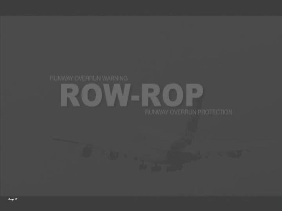
RAA
•Preventing Runway Incursion: Runway Approaching Advisory
50

RAA
•Preventing Runway Incursion: RAA Illustration (1/2)
7 s 60 m
51

RAA
PFD ND ND
•RWY AHEAD •RWY AHEAD RWY AHEAD •RWY AHEAD RWY AHEAD
52

SIASA project
This project is funded by the European Union and implemented by EASA.
End slide
Evolution Technology for Safety Enhancement
Optimized integration in all Airbus cockpits