Embed Size (px)
Citation preview

Rev. 0.1 5/08 Copyright © 2016 by Silicon Laboratories Si4731-DEMO
Si4731-DEMO
Si4731 DEMO BOARD USER’S GUIDE
1. Features Worldwide FM band support, 76–108 MHz
Worldwide AM band support, 520–1710 kHz
Auto seek/auto scan
48 FM and 48 AM station presets
FM Radio Data Services (RDS) decoding (Pi Pty Ps RT CT AF displays)
Automatic set time/date function via RDS
Automatic Alternative Frequency (AF) switching
Automatic AM channel spacing detection
Single battery operation down to 0.9 V or three battery operation
Adjustable parameters includeTuning spacingSeek SNR/RSSI thresholdsSoft mute SNR/RSSI thresholdsChannel filtersStereo and mono blend thresholdsBand limitsDe-emphasis (50 or 75 µs)AM channel spacing detection threshold
Stereo/mono indicator
Volume control with mute function
AM/FM band and signal quality indicator display
Battery voltage indicator
Calendar display
3x4 matrix keypad interface
Direct input of station frequencies
2. Overview
The Silicon Laboratories Si4731-DEMO board provides a complete portable AM/FM radio design with numerousenhanced features that demonstrate the capabilities of the Silicon Laboratories AM/FM and MCU product families.The Si4731-DEMO comes in a 3x3 mm 20-pin QFN package and is layout compatible with the entire Silicon LabsSi47xx radio family of FM receivers, transmitters, and transceivers. The host MCU is a Silicon LaboratoriesC8051F930 with internal oscillator and built-in DC-DC converter. A 79 x 101 dot matrix LCD provides the flexibilityto display a variety of system information including RDS. The demo board can work with either one AA batteryusing the dc-dc converter of the C8051F930 MCU or three AAA batteries.

Si4731-DEMO
2 Rev. 0.1
3. Description
Figure 1 and Figure 2 shows the physical layout of the board with key components indicated.
Figure 1. Si4731-DEMO Board Top Side in Calendar Mode
Figure 2. Si4731-DEMO Board Bottom Side
S14J15J1
4312
LCDJ14
J4
U1 U2J2
J3
JP2
T1
JP3JP4
JP1 S15
U4
Reset Key
KeyPad
U3
J5

Si4731-DEMO
Rev. 0.1 3
Power:
S14: 3 cell / 1 cell selection
S15: Power on / off
Audio connectors:
J14: Audio input (unused)
J15: Audio headphone output
Antenna selections:
J1: FM whip antenna connector
J2: FM SMA connector for FM conductive testing
J3: AM SMA connector for AM conductive testing
J4: AM air loop antenna wire connector
J5: JTAG connector
T1: Transformer for AM air loop operation (not shown)
JP1: FM antenna input selection
JP2: AM signal input selection
JP3: AM antenna type selection
Open: AM ferrite loop stick antenna
Short: AM air loop antenna
JP4: FM PCB antenna selection
Short: Embedded PCB trace as FM short antenna for Si4704/05/1x/2x
Open: No PCB short antenna
Main components:
LCD: 79x101 dot matrix LCD
U1: Silicon Laboratories Si4731 AM/FM/RDS tuner
U2: Audio amplifier
U3: Silicon Laboratories C8051F930 MCU
U4: LDO
Control interface:
Reset Key: Reset button
KeyPad: 3x4 matrix buttons for human interface
1-2: FM SMA (J2)1-3: FM whip antenna (J1)1-4: FM headphone (J15)
3
42
1
1-2: AM ferrite loop stick1-3: AM air loop (J4)1-4: AM SMA (J3)
3
4
2
1

Si4731-DEMO
4 Rev. 0.1
4. Operation
This section describes the operating modes of the Si4731-DEMO board. The board provides two major modes ofoperation: Calendar and AM/FM radio.
4.1. Calendar ModeUpon power on, the board automatically enters the Calendar Mode and displays the following information:
Year-month-day
Hour-minute
Day of the week
Battery voltage
The demo board display in Calendar Mode is illustrated in Figure 1.
In Calendar Mode, the SET/9 key is used to enter the setup menu. The M+/3 and M-/7 keys are used to selectdifferent adjustable items (hour, minutes, year, day, month). The UP/4 and DOWN/8 keys are used to set the valuefor each selected item.
The Calendar Mode date and time can also be set automatically with RDS Current Time (CT) information from abroadcast radio station as described in the following section.
4.2. AM/FM Radio ModeFrom Calendar Mode, the POWER button is used to enter AM/FM Radio Mode which displays the followinginformation:
1. Signal SNR indicator
2. Signal RSSI indicator
3. Band frequency indicator
4. Battery voltage indicator
5. Band frequency unit indicator
6. Stereo/mono indicator
7. Volume indicator
8. Band indicator
9. RDS information
The demo board display in AM/FM Radio Mode is illustrated in Figure 3 and Figure 4:
Figure 3. LCD Display in FM Radio Mode
7
1 23
4
5
6
8
9

Si4731-DEMO
Rev. 0.1 5
Figure 4. LCD Display in AM Radio Mode
4.2.1. Band Selection
In Radio Mode, the BANDS/0 key is used to switch between the AM and FM bands.
4.2.2. Time/Date Auto Set
Many radio stations broadcast RDS data including clock/time CT information. The AM/FM demo board can capturethis information to automatically set the time and date. In FM Mode, when RDS CT information is received, the CTindicator will be displayed. The MEM/AL/1 button can be used to update the calendar date and time with the CTinformation. CT information is not available on all radio stations and is normally sent only once per minute.
4.2.3. Alternative Frequency (AF) Switching
The AM/FM demo board monitors RDS for alternate frequency (AF) information. When RDS alternative frequencyinformation is received, the AF indicator will be displayed. If the signal quality of the currently tuned stationdegrades, the radio will automatically change to one of the alternative frequency stations.
4.2.4. Tune/Seek
In Radio Mode, pressing the UP/4 or DOWN/8 button for less than 0.5 s will tune the frequency by the preset stepsize. Holding the button for longer than 0.5 s but less than 3 s will perform a station seek.
4.2.5. Scan
In Radio Mode, the MSCAN/5 button is used to scan for all valid stations in the selected band and will automaticallysave them into preset selections. After a scan operation, the M+/3 and M-/7 keys will cycle through the presetstation list. Scan operation can be aborted by pressing MSCAN/5 again, or by pressing the UP/4 or DOWN/8 key.
4.2.6. Parameter Settings
In Radio Mode, the SET/9 key is used to select the parameter setup menu as illustrated in Figure 5 and Figure 6.The M+/3 or M-/7 keys will cycle through the available items in the menu. The UP/4 or DOWN/8 keys are used toset the desired value for each item. Select “Yes” under “Factory Def” to go back to the factory default settings for allitems.
1 3 2
4
7
5
8

Si4731-DEMO
6 Rev. 0.1
Figure 5. LCD Display in FM Setup Menu
Figure 6. LCD Display in AM Setup Menu
4.2.7. Digit Keys
In Radio Mode, the FUNC/DIGIT key is used to switch the keypad to digital input mode. A “Dig” indicator isdisplayed in this mode and all keys marked with a digit are used to input a channel frequency. A frequency isconsidered valid if it lies within the band limits. If a non-valid frequency is entered, the closest band limit will beentered and displayed.
4.2.8. Volume
The VOL+/2 or VOL–/6 keys are used to adjust the volume up or down. The board audio output will be muted whenvolume is at the lowest setting.
4.2.9. AM Channel Spacing Auto Set
In AM Mode, the MEM/AL/1 key will automatically detect and set the channel spacing to either 9 or 10 kHz. Thedetection criterion determines which channel spacing results in more valid stations during a band scan. Thenumber for the detection threshold is adjustable as described in Table 2. This operation can be aborted by pressingthe MEM/AL/1 key again.
Si4731-DEMO
Rev. 0.1 7
5. Human interface
There are 12 keys for controlling the demo board as shown in Figure 7:
Figure 7. Human Interface Keys
Each key can have a different function under each operating condition:
Calendar/Powerdown Mode: Radio function is disabled. LCD displays Calendar. Buttons can be used to set time, etc.
Radio AM/FM Mode: Tuner IC works in powerup mode (FM or AM). Radio function is enabled. LCD displays the radio station parameters. Buttons are used to adjust radio settings.
Digital Input Mode: Tuner IC works in powerup mode (FM or AM). Radio function is enabled. LCD displays the radio station parameters. The buttons are used for direct digit input of station frequencies.
The functions of the buttons are summarized in Table 1:
Table 1. Key Function Description
Button/Mode Calendar Mode
Tuner Off
Radio AM/FM Mode
Tuner On
MEM/AL/1 None FM Mode: Used to adjust calendar using received RDS CT.AM Mode: Used to automatically detect and set the channel spacing.
POWER Enable radio Disable radio function and enter calendar mode. (Radio parameters will be saved to Flash).
SET Enter calendar setup menu
Enter radio setup menu. (Parameter list in Table 2)
BANDS None Change between FM and AM band.
UP/DOWN
Hold Time < 0.5 s
In setup menu, change the current
calendar item by one step.
In setup menu, change the current parameter by one step.In radio mode, tune up or down by one step.
0.5 s <Hold Time< 3 s
Perform a station seek.
Hold Time> 3 s
Fast parameter setting Fast parameter setting.
MSCAN None Scan for all valid stations and save them to presets.
Note: Combination keying is entered and exited from Radio Mode by pressing and holding the SET key then pressing the BANDS key. A combination of the SET and the MSCAN keys will cycle through the available display items.
MEM/AL/1
MSCAN/5
SET/9
VOL+/2
VOL-/6
M+/3 UP/4
M-/7 DOWN/8
BANDS/0 FUNC/DIGIT POWER

Si4731-DEMO
8 Rev. 0.1
The FM and AM radio parameters which can be configured from setup menu are listed below in Table 2.
M+/ M– In setup menu, select next calendar item.
In setup menu, select next adjustable item.In radio mode, tune to the next preset station.
Vol+ / Vol–
< 3 s None Increase or decrease volume 1 step.
> 3 s Quickly increase or decrease volume.
FUNC/DIGIT None Shift the keyboard between normal function and digital input mode.
Combination keying
None A: Radio IC versionB: Firmware versionC: Varactor reading
D: AGC status
Table 2. Radio Configuration Parameters
FM Parameter AM Parameter
Spacing: 50/100/200 kHzDefault: 100 kHz
Spacing: 1/9/10 kHzDefault: 9 kHz
RSSI Seek: 0–127 dBµVDefault: 20 dBµV
RSSI Seek: (0–63 dBµVDefault: 25 dBµV
SNR Seek: 0–127 dBDefault: 03 dB
SNR Seek: 0–63 dBDefault: 05 dB
Pre-emphasis: 50 or 75 µsDefault: 75 µs
Pre-emphasis: 00 disable, 50 µsDefault: 00
Band High Threshold: Max 108 MHzDefault:107.90 MHz
Band High Threshold: Max 1710 kHzDefault:1710 kHz
Band Low Threshold: min 76 MHzDefault: 87.50 MHz
Band Low Threshold: min 520 kHzDefault: 522 kHz
Channel Filter: 00/40/60/80/100 kHzDefault: 00 (Auto)
Channel Filter: 1/2/3/4/6 kHzDefault: 2 kHz
RClock: 0: AFC disable32763~32773Default: 32768
RClock: 0 AFC disable32763~32773Default: 32768
Smute Rate: 0–255Default: 64
Smute Rate: 0–255Default: 64
Smute SNR: 0–15 dBDefault: 4 dB
Smute SNR: 0–63 dBDefault: 10 dB
Smute Attenuation: (0–31 dB)Default: 16 dB
Smute Attenuation: 0–63 dBDefault: 16 dB
Table 1. Key Function Description (Continued)
Button/Mode Calendar Mode
Tuner Off
Radio AM/FM Mode
Tuner On
Note: Combination keying is entered and exited from Radio Mode by pressing and holding the SET key then pressing the BANDS key. A combination of the SET and the MSCAN keys will cycle through the available display items.

Si4731-DEMO
Rev. 0.1 9
Blend Mono: 0–127 dBµVDefault: 30 dBµV
Smute Slop: 1–5Default: 2
Blend Stereo: 0–127 dBuVDefault: 49dBuV
Set Factory Default: on/offDefault:off
AGC Override: on/offDefault: off
AM Channel Spacing Detection Threshold: 1,2,3,4,5,6 Default = 2
AGC Index: 0–26Default : 0
Set Factory Default: on/offDefault:off
RDS/RBDS Default: RBDS
Table 2. Radio Configuration Parameters (Continued)

Si4731-DEMO
10 Rev. 0.1
6. Bill of Materials
C8051F930 MCU with 64 kB Flash program memory, 4 kB RAM, and built-in dc-dc converter
AM/FM receiver IC Si4731 with external 32768 Hz crystal oscillator support
ST7588T LCD driver IC
LM4910 Audio amplifier IC
See Table 3 for details.
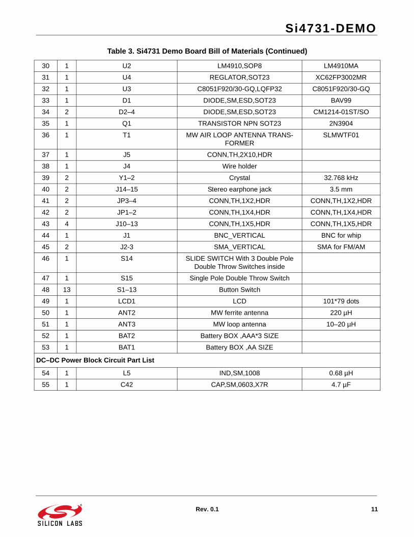
Table 3. Si4731 Demo Board Bill of Materials
Item Qty Reference Description Value
1 3 C1, C16, C29 CAP,SM,0603,X7R 0.47 µF
2 2 C4, C13 CAP,SM,0603,X7R 4.7 µF
3 8 C15, C23-28, C41 CAP,SM,0603,X7R 1 µF
4 6 C10, C14, C19, C37, C39–40 CAP,SM,0603,X7R 0.1 µF
5 4 C2 ,C3, C21–22 CAP,SM,0603,X7R 22 pF
6 2 C8, C12 CAP,SM,0603,X7R 220 pF
7 2 C11, C18 CAP,SM,0603,X7R 820 pF
8 3 C5–7 CAP,SM,0603,X7R 100 pF
9 4 C17, C38, C44, C46 CAP,SM,0603,X7R 1 nF
10 8 C32–36, C54–C55 ,C43 CAP,SM,0603,X7R NP
11 3 C30 ,C45, C53 RES,SM,0603 0R
12 1 C9 CAP,SM,1210,tantalum 100 µF/6.3 V
13 1 C31 CAP,SM,1210,tantalum 220 µF/4 V
14 4 R1–2, R3 ,R25 RES,SM,0603 0R
15 11 R7, R27, R29–32, R34, R36–39 RES,SM,0603 10 kW
16 2 R5, R11 RES,SM,0603 12 kW
17 4 R20, R22–23, R28 RES,SM,0603 1 kW
18 2 R4,R6 RES,SM,0603 5k6
19 2 R8, R10 RES,SM,0603 6k8
20 3 R9, R16–17 RES,SM,0603 2 kW
21 2 R18–19 RES,SM,0603 100R
22 5 R15, R21 ,R24, R26 ,R35 RES,SM,0603 NP
23 1 R12 RES,SM,0603 4k7
24 3 R13–14, R33 RES,SM,0603 100k
25 4 B1–4 FERRITE BEAD,SM,0805 2k5/100M
26 1 L1 IND,SM,0603 120 nH
27 1 L2 IND,SM,0603 270 nH
28 2 L3–4 RES,SM,0603 0R
29 1 U1 Si47xx, MLP20-3MM Si47xx
Si4731-DEMO
Rev. 0.1 11
30 1 U2 LM4910,SOP8 LM4910MA
31 1 U4 REGLATOR,SOT23 XC62FP3002MR
32 1 U3 C8051F920/30-GQ,LQFP32 C8051F920/30-GQ
33 1 D1 DIODE,SM,ESD,SOT23 BAV99
34 2 D2–4 DIODE,SM,ESD,SOT23 CM1214-01ST/SO
35 1 Q1 TRANSISTOR NPN SOT23 2N3904
36 1 T1 MW AIR LOOP ANTENNA TRANS-FORMER
SLMWTF01
37 1 J5 CONN,TH,2X10,HDR
38 1 J4 Wire holder
39 2 Y1–2 Crystal 32.768 kHz
40 2 J14–15 Stereo earphone jack 3.5 mm
41 2 JP3–4 CONN,TH,1X2,HDR CONN,TH,1X2,HDR
42 2 JP1–2 CONN,TH,1X4,HDR CONN,TH,1X4,HDR
43 4 J10–13 CONN,TH,1X5,HDR CONN,TH,1X5,HDR
44 1 J1 BNC_VERTICAL BNC for whip
45 2 J2-3 SMA_VERTICAL SMA for FM/AM
46 1 S14 SLIDE SWITCH With 3 Double Pole Double Throw Switches inside
47 1 S15 Single Pole Double Throw Switch
48 13 S1–13 Button Switch
49 1 LCD1 LCD 101*79 dots
50 1 ANT2 MW ferrite antenna 220 µH
51 1 ANT3 MW loop antenna 10–20 µH
52 1 BAT2 Battery BOX ,AAA*3 SIZE
53 1 BAT1 Battery BOX ,AA SIZE
DC–DC Power Block Circuit Part List
54 1 L5 IND,SM,1008 0.68 µH
55 1 C42 CAP,SM,0603,X7R 4.7 µF
Table 3. Si4731 Demo Board Bill of Materials (Continued)
Si4731-DEMO
12 Rev. 0.1
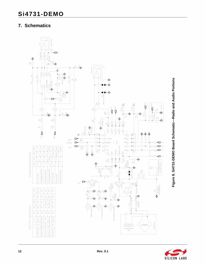
7. Schematics
Fig
ure
8.S
i47
31-D
EM
O B
oar
d S
ch
ema
tic—
Ra
dio
an
d A
ud
io P
ort
ion
s
Si4731-DEMO
Rev. 0.1 13
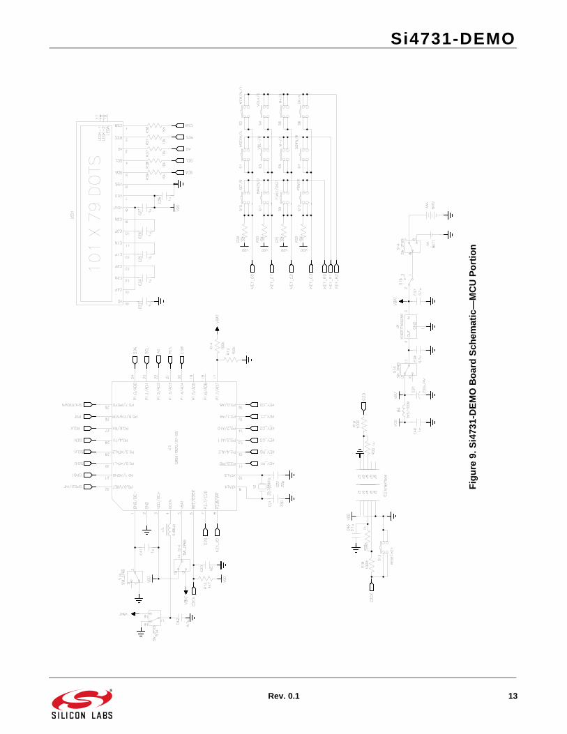
Fig
ure
9.
Si4
731-
DE
MO
Bo
ard
Sch
em
atic
—M
CU
Po
rtio
n

DisclaimerSilicon Laboratories intends to provide customers with the latest, accurate, and in-depth documentation of all peripherals and modules available for system and software implementers using or intending to use the Silicon Laboratories products. Characterization data, available modules and peripherals, memory sizes and memory addresses refer to each specific device, and "Typical" parameters provided can and do vary in different applications. Application examples described herein are for illustrative purposes only. Silicon Laboratories reserves the right to make changes without further notice and limitation to product information, specifications, and descriptions herein, and does not give warranties as to the accuracy or completeness of the included information. Silicon Laboratories shall have no liability for the consequences of use of the information supplied herein. This document does not imply or express copyright licenses granted hereunder to design or fabricate any integrated circuits. The products must not be used within any Life Support System without the specific written consent of Silicon Laboratories. A "Life Support System" is any product or system intended to support or sustain life and/or health, which, if it fails, can be reasonably expected to result in significant personal injury or death. Silicon Laboratories products are generally not intended for military applications. Silicon Laboratories products shall under no circumstances be used in weapons of mass destruction including (but not limited to) nuclear, biological or chemical weapons, or missiles capable of delivering such weapons.
Trademark InformationSilicon Laboratories Inc., Silicon Laboratories, Silicon Labs, SiLabs and the Silicon Labs logo, CMEMS®, EFM, EFM32, EFR, Energy Micro, Energy Micro logo and combinations thereof, "the world’s most energy friendly microcontrollers", Ember®, EZLink®, EZMac®, EZRadio®, EZRadioPRO®, DSPLL®, ISOmodem ®, Precision32®, ProSLIC®, SiPHY®, USBXpress® and others are trademarks or registered trademarks of Silicon Laboratories Inc. ARM, CORTEX, Cortex-M3 and THUMB are trademarks or registered trademarks of ARM Holdings. Keil is a registered trademark of ARM Limited. All other products or brand names mentioned herein are trademarks of their respective holders.
http://www.silabs.com
Silicon Laboratories Inc.400 West Cesar ChavezAustin, TX 78701USA
Smart.Connected.Energy-Friendly
Productswww.silabs.com/products
Qualitywww.silabs.com/quality
Support and Communitycommunity.silabs.com