Embed Size (px)
Citation preview
NASA Technical Memorandum 89114
SHUTTLE TO SHUTTLE I1:SUBSYSTEM WEIGHT REDUCTIONPOTENTIAL
(Estimated 1992 Technology Readiness Date)
(NASA-TM-89114) SHU[TLE TO SHUTTLE 2: N90-2858_
SUBSYSTEM WEIGHT RtO_JCTION POTENTTAL
(ESTIMATED 19o2 TECHNOLnGY READINPSS DATE)
(NASA) 54 p CSCL 22B UncIds
G3/16 0304_53
lan O. MacConochie
May 1988
Date for general release May 31_ 1990
Nallonal Aeronautics andSpace Administration
langley R_4N_h C4mt_Hampton, Virginta 23665
https://ntrs.nasa.gov/search.jsp?R=19900019273 2020-08-06T19:22:15+00:00Z


Introduction --
Subsystems
TABLE OF CONTENTS
Page
23
1.0 Wing Gr()up
2.0 Tail Gr()up
3.0 Body Group4.0 Thermal Protection System
5.0 Landing and Auxiliary Systems
6.0 Propulsion - Ascent7.0 Reaction1 Control System (RCS)
8.0 Orbital Maneuvering System (OMS)
9.0 Prime Power
10.0 Electrical Conversion and Distribution
11.0 Hydraulic Conversion and Distribution12.0 Surface Controls
13.0 Avionics
14.0 Environmental Control and Life Support
15.0 Personnel Provisions
Discussion
Table I: Summ,lry of Technology Factors
Table II: Summlry of Configuration Factors
Summary
3
g
12
22
29
30
33
33
34
36
37
38
40
42
43
495051
-i-


Explanatory Note
This document has been prepared in support of an in-house study of an
advanced Shuttle, referred to herein as Shuttle II. The following sections
are numbered by subsystem with the same numbering system used for the
current Shuttle in reporting mass properties. This numbering system is, in
turn, patterned after MIL spec 38310 used for reporting mass properties in
the aerospace and aircraft industries. Figures accompany each section and
are designed as figures 1.1, 1.2, etc. References are similarly numbered.
As an exception to the above numbering system, figures accompanying the
discussion section are designated D-l, D-2, etc.
Introduction
The current Space Shuttle has considerable capability with regard to the
crew size, the length of orbital stay time, and the payload support
provided. The technology level that supported the development of this
capability is that associated with the seventies and earlier; additional
(advanced) technologies available at the time of the vehicle design werenot utilized for cost reasons. All of these factors tend to make the
Shuttle system large.
The NASA Langley Research Center has been conducting studies to determine
the impact of advanced technologies on the next generation Space Shuttle
(Shuttle II). This vehicle is envisioned to be manned and to have a
20,000- to 40,000-1b payload capability. A containerized cargo system is
used with the container mounted on top of the vehicle. Most of the support
requirements for the payload are charged to payload accommodation and do
not appear in the basic vehicle dry weight.
In the following sections, current Shuttle subsystems are identified, and
estimates for weight reduction potential for the advanced (Shuttle II)
subsystems are given. The weight savings, or reduction, for each Shuttle
II subsystem is expressed as a percent of the corresponding Shuttle Orbiter
subsystem weight. These weight savings projections have been compiled as
an aid for those involved in weight estimation of future shuttles.
Weight reductions are classified as technological or configurational.
Technology weight savings are those obtained from advances in the
state-of-the-art, for example, by substituting an advanced material for acurrent Shuttle material or by using Shuttle flight experience to better
define the aerodynamic and aerodynamic-heating environments. Configuration
factors are those associated with a reduction in vehicle weight such as
reducing crew cabin size or shortening the mission.
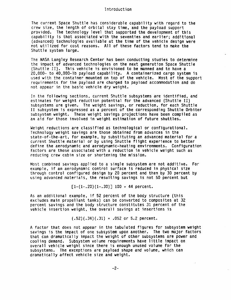
Most combined savings applied to a single subsystem are not additive. For
example, if an aerodynamic control surface is reduced in physical size
through control configured design by 20 percent and then by 30 percent by
using advanced materials, the resulting savings is not 50 percent but
[1-(1-.20)(1-.30)] 100 = 44 percent.
As an additional example, if 52 percent of the body structure (this
excludes main propellant tanks) can be converted to composites at 32percent savings and the body structure constitutes 31 percent of the
vehicle insertion weight, the overall savings at insertions is
(.52)(.34)(.31) = .052 or 5.2 percent.
A factor that does not appear in the tabulated figures for subsystem weight
savings is the impact of one subsystem upon another. The two major factors
that can dramatically impact the weight of other subsystems are power and
cooling demand. Subsystem volume requirements have little impact on
overall vehicle weight since there is enough unused volume for the
subsystems. The exceptions are payload shape and volume, which can
dramatically affect vehicle size and weight.
-2-

Subsystems
1.0 Wing Group
Aluminum skin-stringer aluminum honeycomb, and some composite structures
are being used on the l:urrent Shuttle wing. Mechanical fasteners are used
for joints. An advanced structural wing, however, could be fabricated
entirely from high strength organic or metallic composites, titanium,advanced aluminum, or high temperature superalloys. Bonding (as opposed to
fastening) could be ut lized particularly on the organic composites for a
substantial weight sav ngs.
With regard to the str_Jctural concept for an advanced wing, the entire
upper and lower surfaces could be constructed from a honeycomb sandwichwith a probable weight advantage. At present, a large section of the wingsurface on the Shuttle Orbiter is made from aluminum honeycomb with the
elevon hingeline seals made either from Inconel or titanium honeycombsandwich, and the elev,)ns made from aluminum honeycomb sandwich--the latter
protected with reusable surface insulation (Fig. 1.1).
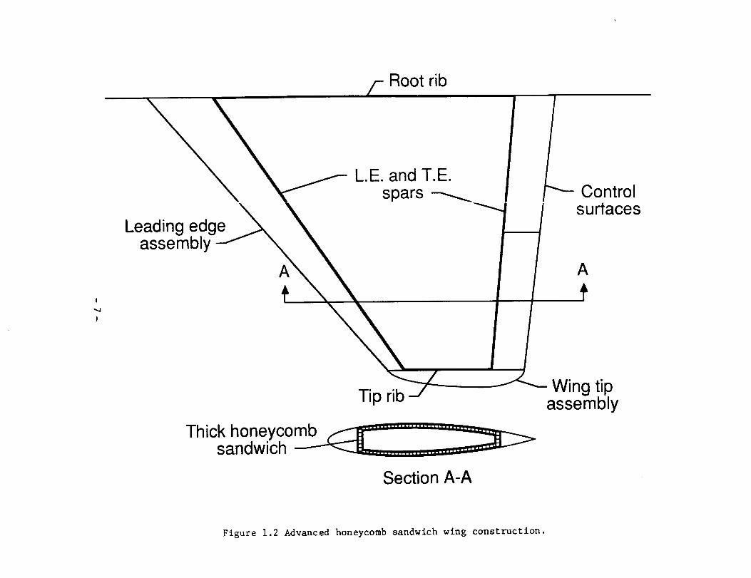
From the standpoint of wing internals, a wing was proposed in Reference 1.1in which only two ribs and two spars (one leading edge and one trailing
edge spar) were utilized (Fig. 1.2). A static loads analysis, using afinite element program, showed that the wing could withstand the ultimate
loading condition with about a lO-percent margin over the 2.5g subsonicmaneuver requirement. A factor that enhances the feasibility of the muchreduced internal structure for the advanced Shuttle-type wings is the large
difference in wing thickness of the clipped delta configurations compared
with, for instance, a modern fighter aircraft. The latter wing thicknessis that associated wit_l a 3 to 7 percent chord as compared with a 10 to 12
percent chord used for the Shuttle-type vehicles.
By combining honeycomb, bonding for fasteners, and advanced structural
concepts such as that suggested in Reference 1.1, a combined savings in
wing weight of 44 perc,_nt is projected. In addition, a 20-percentreduction in wing area is projected through the application of control
configured design (Ref. 1.2). More accurate air data systems should makecontrol configured design possible with somewhat greater relaxation in
stability levels (Ref. 1.3).
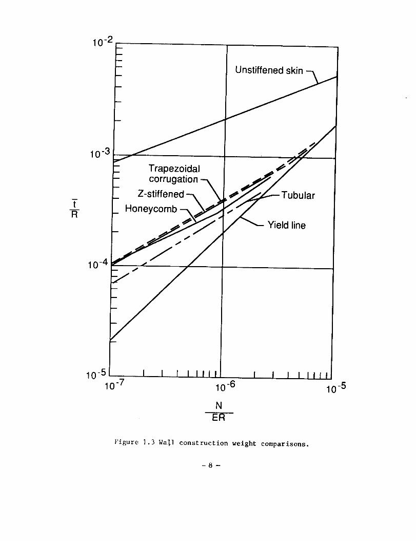
The assumption of a weight savings through the use of honeycomb is based on
data showing honeycomb as the most efficient structure fo£ carrying
in-plane compressive l)ads (Ref. 1.4 and Fig. 1.3). The t value representsthe equivalent solid t;lickness of the panel in inches, and R equals panelradius of curvature in inches. The load, N, is given in pounds per inch of
circumference. The E is the modulus of the material in pounds per square
inch.The tubular struc:ure shown does not qualify as the lightest in an
integrated wing design, since the surface is corrugated. Fairings, orcarrier panels, would I)e required for installation of reusable surface
insulation and would cq)nstitute a weight addition.
-3-

Wing Weight Savings Summary
Item Projected Classifi-
Savings, % cation
Materials and Construction
Composites for aluminum, bonding
for fasteners, honeycomb for
skin-stringer construction (3O)
44 Technology
Elimination of wing internals with
exception of forward and aft spars
and root and wing tip ribs (20)
Control Configured Design
(allowing for reduced wing area)
20 Configura-tion
-4-
1.1
1.2
1.3
1.4
MacConochie, I. C., LeMessurier, R. W., and Bailey, J. P.: "Large
Delta Wings for Earth-to-Orbit Transports," Journal of Spacecraft and
Rockets, Vol. 17, No. 5, September-October 1980.
Freeman, Delma C., Jr. and Wilhite, Alan W.: "Effects of Relaxed
Static Longitudiral Stability on a Single-Stage-to-Orbit Vehicle
Design" NASA TP ]594, December 1979.
Pruett, C. D., Wolf, H., Heck, M. L., and Siemers, P. M., Ill:"Innovative Air Data System for the Space Shuttle Orbiter," Journal of
Spacecraft and Rockets_ Vol. 20, No. 1, January-February, 1983.
Shideler, J. L., Anderson, M. S., and Jackson, L. R.: "Optimum Mass-
Strength Analysi_ for Orthographic Ring-Stiffened Cylinders Under
Axial Compressior_" NASA TN D-6772, July 1972.
-5-

!
!
Honeycombs
Aluminum
Titanium
Inconel
o-**,
Figure i.i Shuttle Orbiter wing honeycomb usage.
!
I
Leading edgeassembly
Root rib
L.E. and T.E.spars _- Control
surfaces
A
Thick honeycombsandwich
Tip rib
Section A-A
Wing tipassembly
Figure 1.2 Advanced honeycomb sandwich wing construction.
10-2
10 3 _
- Trapezoidal .,_ _'_"
- corrugation ---_ _,_/
- Z-stiffened -_ '_, _j,;,'___----- Tu bu lar
- Honeycomb --_=_ _
..p,_J-_ _ Yield line
10_4 _11/
10-5 I I I I IIII I I I t t_t
10 -7 10 -6 10 -5
N
ER
Figure 1.3 WaS1 construction weight comparisons.
-8-

2.0 Tail Group
The current Shuttle Orbiter tail consists of aluminum skin-stringer
construction for the fin with aluminum honeycomb covers for the rudder
hingeline seals (Fig. 2.1). Spars are machined and ribs are fabricatedfrom aluminum sheet metal.
By using a concept similar to that proposed for the advanced wing
(Fig. 1.2) for the vertical tail, a weight savings is projected. Also byutilizing a forward-located fin, referred to as a dorsal (Ref. 2.1), or tip
fins (Ref. 2.2) and using active controls, the size and weight of thedevices used for directional control can be dramatically decreased.
If tip fin controllers are utilized during entry in lieu of a large
vertical tail, the use of reaction control system (RCS) jets for yaw
control can be discontinued earlier in the flight (M :3). The present
Orbiter uses the RCS system down to about Mach I (Ref. 2.2).
The secondary effect on the RCS system of reduced RCS propellant is not
included in the figuFes below. This could amount to about a 200-pound
savings in RCS propellant for a vehicle having an entry weight of 300,000
pounds. Also not included is a reduction in overall system weight derived
from the reduced ascent drag and reduced requirements on the actuation and
power subsystems for the much smaller tip fins or dorsal.
Tail Weight Savings Summary
Iten Projected Classifi-Savings, % cation
Similar material and construction
to that of the advanced wing 44 Technology
Materials
Construction
Dorsal or tip fin cDntrollersin lieu of tail .........
(30)
...... (20)
40* to Configura-70 tion
*Based on estimates from size of dorsal and actuator power requiredcompared to a vertical tail in reference 2.1. For tip fins, estimatedsavings is based on lata presented to JSC Shuttle program management onLaRC Tip-Fin Controller Study on September 28, 1983. An estimate is madefor the weight penalty required for separate speed brakes when using adorsal.
-9-

2.1
2.2
Lepsch, R. A. and MacConochie, I. 0.: "Subsonic Aerodynamic
Characteristics of a Circular Body Earth-to-Orbit Transport."
Presented at the AIAA 4th Applied Aerodynamics Conference, San Diego,California. Paper No. AIAA 86-1801-CP, June 9-11, 1986.
Powe11, R. W. and Freeman, D. C., Jr.: "Aerodynamic Control of theSpace Shuttle Orbiter with Tip-Fin Controllers." Journal of
Spacecraft and Rocketsl VoI. 22, No. 5, September-October 1985.
-10-

I
I
Honeycombs
Aluminum
Inconel
Figure 2.1 Shuttle tail honeycomb usage.

3.0 Body Group
The structural material in the current Shuttle Orbiter body is primarily
aluminum. Conventional skin-stringer construction is used extensively
throughout. Some components, such as the crew module shell, are integrally
stiffened using sections from thick machined aluminum plates. Organic
composite honeycomb sandwich is used for the cargo bay doors, and superalloy honeycomb sandwich is used for the base close-outs around the
engines. A section of the sides of the body along the wings is aluminum
honeycomb (Fig. 3.1). Portions of the engine thrust structure and other
body truss structure are fabricated from metallic composites. By
necessity, the overall body structure on the Shuttle Orbiter is complex
when compared with a vehicle having large internal tanks and large areaswith fewer cutouts. The current Shuttle has approximately 60 cutouts for
access and vent panels and other penetrations (Ref. 3.1 and Fig. 3.2).Also, discontinuities are present in the body moldline for the pilot's
canopy and for the orbital maneuvering system (OMS) pods. These cutoutsand discontinuities constitute substantial structural and thermal
protection system (TPS) weight penalities. (Note: TPS is usually
densified around a cutout.) Every effort should be made to reduce, if
possible, the number of penetrations in the body shell for the
considerations given above. For operational considerations, increased
access is usually sought, not decreased, making it desirable to establish a
trade between an extra pound of structure in orbit versus a unit of time
saved on the ground for operations.
One of the biggest drivers in structural weight for future Earth-to-orbit
transports is the overall body shape. By using a simple circular shape, asavings of 40 to 60 percent is easily achievable through the reduction in
body shell wetted area and unit weight over an oblate cross section(Fig. 3.3 and Ref. 3.2). Conceivably, the entire body she11, could be
fabricated from honeycomb sandwich and overwrapped with composites.
Straight pultruded composite sections could be used where needed for cargo
bay door frames and cargo support structure (Refs. 3.3 and 3.4).
In a recent contractual study, an estimate was made of the possible savings
from substituting composites for aluminum in the fuselage of largetransport aircraft (Ref. 3.5). In accordance with the study guidelines,
cabin window spacing could not be changed; therefore, optimum ringframestructure could not be achieved. Damage tolerance of the exposed face
sheet of the honeycomb sandwich dictated the face sheet thickness. Even
with design constraints, the projected savings in the body shell for the
transport was 22.7 percent when substituting graphite-epoxy composites foraluminum.
In addition to providing protection for an advanced Shuttle during severe
entry heating, the thermal protection system would also protect a honeycomb
sandwich fabricated from ultra-thin face sheets from casual damage.
Presumably, the interior face sheet could be protected from damage during
manufacture. In view of the casual damage and non-optimum constraints of
the commercial airplane study, an additional 9-percent advantage is assumed
for a Shuttle II, making the assumed structural savings possible equal to
23 plus 9, or 32, percent.
-12-

Titanium is often con_idered as a structural material for high performance
(Shuttle-like) vehicles. Titanium and aluminum structure weigh about the
same, but titanium ha_ about twice the temperature capability. If titaniumwere to be used for the structure on a Shuttle II vehicle, some of the
external insulation c,)uld be either reduced in thickness or, in the lower
temperature regions, eliminated altogether. However, a composite structureis much lighter than either titanium or aluminum, and may result in a
lighter vehicle than .in all titanium structure with limited areas in which
the thermal protectiol has been removed or reduced in thickness.
For purposes of consistency, the main propulsion tanks, whether they are
integral or non-integral, are listed in the body group. In earlier mass
properties reports, n)n-integral tanks have been listed in the propulsion
group.
The propellant tanks For future Shuttles must be reusable. Therefore, thetank walls must be thicker to survive cyclic loads. Customarily the liquid
oxygen tanks are placed in the aft portion of future Shuttles and areintegral with the bod_ structure. Therefore, they must carry the bending
and inertial loads of everything ahead of the tank. To efficiently carry
compressive loads, some type of stiffener must be added to reinforce thetank wail. The LOX tlnk, located forward in the external tank (ET) on the
current Shuttle, is n)t provided with wail stiffeners. This tank only has
two ring frames for i_ternal support to which a slosh baffle assembly is
attached.
The liquid hydrogen tlnk on most future Shuttles is placed forward and must
withstand nose gear slapdown loads, as well as other body loads. The
aft-located hydrogen tank in the Shuttle ET must carry the compressivethrust loads from the Shuttle's main engines. This thrust is transmitted
through the aft ET fittings and provides the force to accelerate the ET and
its propellant load. (Prior to staging of the solids, most of theacceleration thrust is transmitted through the solid rocket motor forward
fittings.)
Whereas more conventional methods of construction were used on the Shuttle
ET, honeycomb sandwich may be the construction of the future for theadvanced Shuttles for the following reasons:
1) The honeycomb sandwich can carry compressive loads more efficiently
than skin stringer construction (Fig. 1.3).
2) The honeycomb sandwich is smooth on both sides making iteasier to attach insulation either internally or
externally. This is not true of corrugated or blade-stiffened tank
wail construction.
3) The two walls provide redundancy for the containment of a fluid.
-13-

4) Finally, honeycombsandwich mayafford the only practical meansfor the inspection of a tank for micro-leaks. This could beachieved by using an infrared imaging camera that would detectleakage of cryogenic fluids. The camera would be deployed eitherinternally in an empty tank or externally to scan for leaks; theexact method used would depend on insulation location and otherconsiderations. Honeycombcells (into which propellant or air hadleaked) would show up as cooler or warmer areas depending on heatflow direction relative to the infrared camera location.
An integral tank/hot structure was reported by the Boeing CompanyinReference 3.6. In this design, a titanium honeycombsandwhich was used forthe upper half of the body shell, while a Ren_41 honeycombsandwich wasused for the bottom half. Becausethe shell cross section was oblate,the tank had to be braced internally to maintain its shape under pressure.
In an in-house study (Ref. 3.7), a somewhatsimilar approach was taken fortank design except that all of the honeycombsandwich shell was fabricatedfrom Inconel 718, and further, the shell had a circular shape. Inconel 718structure has a lower strength-to-density ratio, but the advantages of thealternate design are fourfold, namely: a) Inconel 718 is less susceptibleto hydrogen embrittlement than titanium; b) by using a single material forthe shell, the difficulty of joining titanium to Ren_41 is eliminated; c)Inconel 718 can be easily field-repaired by brazing; and d) by making thebody shell circular, the necessity for tension ties and muchheavier ringframes is eliminated.
Recently, someanalytical studies have been conducted (in house) of ahoneycombsandwich tank*. The tank consists of an aluminum liner, afoam-filled organic honeycombcore, and a graphite composite overwrap(Fig. 3-4). The overwrap is placed in tension during the fabricationprocess. This places the aluminum liner in compression and reduces thetensile stresses in the aluminum during tank use. The result is a tankwith extended life by virture of reduced tensile stresses during cyclicloading. This design would also require sometype of external insulationif the tank wall is exposed to reentry heating.
Manufacturing experience with filament winding has shownthat this methodof fabrication is approximately one third the cost of hand layup per poundof material (Ref. 3.8) and is cheaper per pound of fabricated aluminum incertain applications. Elimination of the aluminum liner would result in aneven greater reduction in the cost of the tank for the fully reusableshuttles. This suggests that there is a need for the development of sometype of simply applied thin membraneliner which is impervious to, andcompatible with, LH2 and LOX.
* Analytical study of the advanced technology tank is being conducted bythe writer, Robert B. Davis, and William T. Freeman, Jr.
-14-

There is considerable historical precedent, both in flight hardware and inresearch, for the use of honeycombsandwich for cryogenic tankage. Thebasis for this assertion is as follows:
Used as Common Bulkheed on Saturn
Honeycomb sandwich wa_ used on the Saturn S-II and S-lVB stages for the
LH2/LOX common bulkheads. The S-II construction consisted of two sheets ofO.062-inch aluminum bonded to a 4.75-inch-thick phenolic honeycomb core.
The S-IVB constructior consisted of two sheets of aluminum--one 0.032
inch thick and one 0.C55 inch thick, bonded to a 1.75-inch-thick fiberglass
core (Ref. 3.9).
Tested as a Tank Wall on a Horizontal-Takeoff SinBle-Stage Shuttle
A series of tests have been made on a Rene 41 honeycomb sandwich to
evaluate its use for an integral tank/fuselage hot structure concept (Ref.
3.6). Test panels were cycled in the laboratory in conditions simulatingthe boost and entry ervironments. The tests demonstrated the durable
nature of the honeyconb and indicated that 500 flights would be anachievable goal. In the integral tank/hot structure concept, a substantial
savings in vehicle weight is achieved through the incorporation of thetank, body, and thermal insulation functions into one honeycomb sandwich.
Reduced Scale Honeyconb Tank Built and Tested for Use as a Shuttle ET
Early in the Shuttle _rogram, an alternative to the aluminum expendable ET
was investigated (Ref. 3.10). The tank wall tested consisted of a
O.25-inch NOMEX honeycomb core bonded with a film adhesive to a O.040-inch
aluminum liner. The toneycomb was then overwrapped with a cloth and wet
wound in the hoop dircction with a O.015-inch-thick layer of glass* and
epoxy. The tank diameter was about one quarter that of the Shuttle tank.The conclusion of the study, for the expendable external tank application,
was that the tank would be cheaper to build but would be heavier. The
reusable graphite com{osite tank being studied by the writer et al. is
projected to be light(r than an insulated conventional all-aluminum or
glass overwrapped tan_.
* E-glass (electrical grade glass)
-15-

Body Weight Savings Summary
Item Projected
Savings, %
Overall body shell configuration such ascircular versus oblate cross section
Classification
Composites for aluminum and
honeycomb sandwich wall con-
struction for skin-stringer
Tanks
(Note: even with advanced technology
the reusablility factor is projected
to yield a tank 10 to 20 percent
heavier.)
40* Configuration
32 Technology
Tanks simple cross section such ascircular versus double lobe or oblate
-10"* Technology
15 Configuration
* Based on comparison of an oblate cross section with non-integral tanks
and a circular cross section with integral tanks (Ref. 3.2).
** Based on the assumption of increasing the wall thickness of the tank by
30 percent to make the tank reusable for at least 500 missions.
-16-

3.1 Anon: "Orbiter Crash and Rescue Manual:" JSC-17952, March 1982.
3.2 MacConochie, lan O. and Klich, Phi]lip J.: "Technologies Involved In
Configuring An Advanced Earth-to-Orbit Transport For Low Structural
Mass." SAWE Paper No. 1380. May 12-14, 1980.
3.3 Thompson, V. and Bradley, R. J.: "Pultrusion of Advanced Composites."
Presented at the Society of Manufacturing Engineers Conference on
Advanced Composites: Design Manufacture and Applications, Los
Angeles, California, June 1-3 1976, SME Paper No. EM76-415.
3.4 Wilson, M.L., MacConochie, I. O. and Johnson, G. S.: "The Pultrusion
Process for Structures on Advanced Aerospace Transportation Systems."
Presented at the 45th Conference of Society of Allied Weight Engineers
Inc, Williamsburg, Virginia, SAWE Paper No. 1741, Boeing Ref.,
May 12-14, 1986.
3.5 Smith, P. J., Thomson, L. W. and Wilson, R. D.: "Development ofPressure Containnent and Damage Tolerance Technology for Composite
Fuselage Structures in Large Aircraft." NASA CR 3996, August 1986.
3.6 Shideler, John L., Swedle, Allen R., and Fields, R.A.: "Development
of Rene 41 Honeycomb Structure as an Integral Cryogenic
Tankage/Fuselage Concept for Future Space Transportation Systems."
AIAA Paper No. 82-0653. Presented at the 23rd Structures, Structural
Dynamics, and Materials Conference, New Orleans, Louisiana, May
10-12, 1982.
3.7 MacConochie, I. C. and Davis, R. B.: "Alternative Designs of Integral
Tanks for AdvancEd Space Transportation Systems" Journal Spacecraft
and Rockets, Vol. 22, No. 4, July-August 1985.
3.8 Freeman, William T., Jr. and Stein, Bland A.: "Filament Winding:
Waking the Sleeping Giant." Aerospace America 2 October 1987, pp.
44-49.
3.9 Tharratt, Charles E.: "SERV - a Reusable Single Stage to Orbit Space
Shuttle Concept. The British Interplanetary Society Journal, Vo1. 28,
January 1975, Pa_es 3-25, NAS8-26341.
3.10 Brown, L. D., Martin, M. J. Aleck, B. J., and Landes, R.: "Composite
Reinforced Propellant Tanks--Space Shuttles." The Grumman
Corporation. CR-134726, February 1975.
-17-

!
..b
!
Honeycomb sandwich
Aluminum
i_ Composite
Figure 3.1 Shuttle honeycomb usage (body).

• (Kluo apIs ]gal) suo1_]auad llaqS Xpoz g'£ aln_!/
ooC3 []C_
°°
I
O_
° ' _00"° .k_/

I
t_C
I 2
ITEM
USABLE CROSS SECTION
STRUCTURALMASS/UNIT LENGTH
CONFIGURATION
1 2
682 m2 (7332 if2)
866 kg/m (582 Ib/ff)
682 m 2 (7332 ft 2)
2218 kglm (1491Iblft)
Figure 3.3 Simple and complex body shapes compared.

Aluminum li
I
I
y////////_9oo_\\\\_\,_60°W/Z/Z/Z//,15°>_\\\\\\\"_9o°,_//////////_4 5°
_////////_
90 °45 °90 °15 °60 °90 °
11
Gr aphi t e / p olyi mide
overwrap
layers 0.006 in. thick
Honeycomb
Figure 3.4 Honeycomb tank wall concept.

4.0 Thermal Protection System
The current Shuttle utilizes various insulations on different portions ofthe vehicle depending upon the thermal and other environmental factors
(Fig. 4.1). A flexible reusable insulation (FRSI) is used in those regions
where temperatures do not exceed 700 ° F.
A potentially more durable reusable surface insulation (RSI) tile has been
thermally tested by the writer. In this shell tile design, an outer shell
is structural and carries the aerodynamic loads while the internally
installed flexible insulation provides the insulation (Fig. 4.2 and U.S.
Patent No. 4,456,208). In comparison, the current RSl tiles carry the
loads and provide the insulation. The sides of the shell tiles tend to be
more highly conductive than the siliceous coatings on RSI tiles. On the
other hand, the flexible insulations have much lower density-conductivity
products. The result is a tile which is lighter than the RSI but slightly
thicker and more durable for the same thermal protection. Much more
testing of the shell tile concept would be required to corroborate these
findings. This would mean testing the tiles for moisture and static and
acoustic loadings. The weight of the shell tile compared with other
designs is depicted in Fig. 4.3.
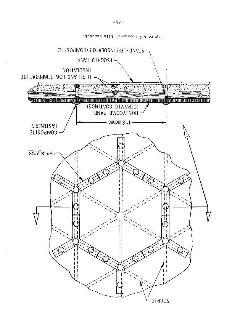
In addition to the shell tile, the writer has thermally cycled a heat
shield having a 5/8-inch-thick brazed titanium honeycomb sandwich as the
outer layer. Flexible high temperature insulation was placed underneath
the honeycomb sandwich. The panel was repeatedly cycled to 1200 ° F without
apparent damage to the outer surface even though the nominal operating
limit for 6AL-4-V is 750 ° F. (However, a slight buckle of the interior
honeycomb face sheet was evident.) The heat shield is designed for
installation on an aluminum tank that is stiffened externally with an
integral isogrid (Fig. 4.4).
A TPS that is similar to the Shuttle Orbiter system can be designed withless conservatism by taking advantage of the lessons learned from the
Shuttle flights (Refs. 4.1 and 4.2).* The peak structural temperatures,
even for the short cross-range flights, were found to be less than
expected. The savings in weight, through a reduction in the current
Shuttle tile thickness, is estimated to average 25 percent. However,
improving the durabililty of the current Shuttle TPS could negate some of
the projected savings (Ref. 4.3). By limiting the vehicles to short cross-
range entries, an estimated 15 percent weight savings in TPS is projectedfrom reference 4.4.
* Note: One factor that added conservatism to the Shuttle tile designs is
an early military requirement that the Shuttle be able to land on the
first orbit of a polar mission.
-22-

Thermal Protection Weight Savings Summary
Item
Lessons learned
Advanced tile design
Limit vehicle to short cross-range entries
Projected Classification
Savings, %
25* Technological
15" Technological
15 Configuration
*The projected savings through technology for Table I at the end of the
paper is (I-[(I-.25)(1-.15)]) X 100 = 36 percent.
-23-
4.1
4.2
4.3
4.4
Anon.: "Shuttle Performance: Lessons Learned." NASA CP-2283,pp. 949-966, 1983.
Throckmorton, D. A., Zoby, E. V., and Kantsios, A. G.: The Shuttle
Infrared Leeside Temperature Sensing (SILTS) Experiment," AIAA 23rd
Aerospace Sciences Meeting, Reno, Nevada; January 14-17, 1985.
Kelly, H. N. and Webb, G. L.: "Assessment of Alternate Thermal
Protection Systems For the Space Shuttle Orbiter. NASA TM-84491,May 1982.
Wurster, K. E. and Eldred, C. H.: "Technology and Operational
Considerations for Low-Heating-Rate Entry Trajectories." Journal of
Spacecraft and Rockets, vo|. 17, No. 5, September-October 1980,pp. 459.
-24-
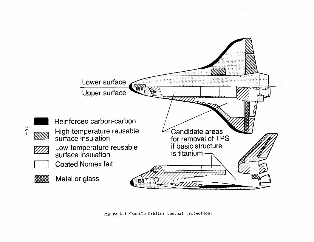
Lower surface
Upper surface
, Reinforced carbon-carbonP_
" High-temperature reusable Candidate areas' _ surface insulation for removal of TPS ._/,_
Low-temperature reusable if basic structure _//j//]surface insulation is titanium ----iN" ._# _/////_
r----] Coated Nomex felt _i_
Metal or glass ___-z/-z/_z__ \ 1__
Figure 4.1 Shuttle Orbiter thermal protection.

SHELL TILE
I
I
Dynamic pressure Dynamic pressure
,asscoating ._._
- . -, L 'oad:::::::::::::::::::::::::::::::::::::::::::::::::::::::::::::::::::::::::::::::::::::::::::::::::::::::::::::::::::
_`:_::_:_::_.:;::_:_:_:_:_:_,:_._;:_.:_;:_:_.:_:_.:;:_.:;:_.:;:_:._;:_._;:_::_:_:_:_..:_:_:_.:.:_:_:_:_.:_pathii_:_i_ii_i_iiiii;i1)?)ii!iiiiiii!!i!:_iii:1_iiii:_i!;_i_i!ii!iiiii:iiiiiiii!!_
Load paths
RSI 9 to 12 Ib/ft3 insulationplus load carrying
Loadcarryi
shell
Flexible insulation1 to 3 1/2 Ib/ft 3
Figure 4.2 Shell Tile and RSI: comparison of concepts.

Unitweight,
Ib/ft 2I
",4
I
2--
1-
0 Various standoff metallic tiles
RSI
rm qhall til_ with RenA 41 cao
0
00
....... o.......::::::::::::::::::::::::::::::::::...........
..........._:...:_:_:.:.iii::iiiiiiiii:_iOili::i_::_::_..........
........._:_:_:_iii!i!i_!:iiiiiiii::i::!i::::_:_.....................,_:_,:::_di:._,:_::_::::::::_::_','_':'::*".... r-l- (Unplublished data by author)
.:iiii_iiiii:ii::::i.........
I I I I I I I I0 1000 1200 1400 1600 1800 2000 2200 2400
Maximum surface temperature, °F
Figure 4.3 Unit weight comparisons for various tile concepts from reference 4.3.
- _Z--
•_deouoa aiTa ieuo_exoH _'9 a]n2T:[
(311SODWO3) _IOIVInSN I/aJO-(]NVIS -_\
_NVlGI_OOS,-_\
3antva]aw31 MO10NV HOIH _ _k \ i
- _,,-_ - -_ ----------- __. _"qqlllilJillflllllgglllllilllflllllgllllllllllllllltllll][i_i_i_g_]_H_|_B_i_i__ i_lilllllillllllllillllglltllll_
- - ,sg ,,vo T13NVd 8VOOA3NOH --' I
./ Isaqou! 8'L L --1
S83N31S V-! /__/311SOdWO3
II
III
OIII
I
II ttlIIeli Ial
I I
1 Ii Ii II I
Q .I I //I /f
flII
II
II
@1890SI

5.0 Landing and Auxiliary Systems
On the current Shuttle, this category includes the main landing gear and
controls, the brakes, and the on orbit payload separation and manipulator
systems. At present, there is no weight allowance for a manipulator arm onthe Shuttle II; this function is performed by an (assumed) Space Station or
space platform manipulator.
For this assumption, ceployment of payloads, other than at a Space Station
or space platform, wobld have to be accomplished using some type of
self-release system, such as guides, or rails and springs. To reduce the
landing gear weight, orag links and other structure could be fabricated
from composites. An oleo main strut could also be filament wound with a
composite but lined with a metal. Since composites are somewhat weak in
compression, the metallic liner could be sized to assume most of the
compressive load of landing while the composite overwrap assumes most of
the hydraulic pressure load. Wheels could conceivably be fabricated from
composites, but no kncwn research is being conducted in this area. Skids
deployed between the n_ain wheels could be used for braking (privatecommunication S. M. Stubbs, Impact Dynamics Branch). Such a braking system
would be more durable inasmuch as skids would support the vehicle in the
event of tire failure.
Landing Gear and Auxiliary Weight Systems Savings Summary
Item ProjectedSavings,
Classification
Eliminate manipulator arm .................. 15.5 Configuration
Increase composite usage in landing
gear 9.0 Technology
-29-

6.0 Propulsion - Ascent
The current Shuttle employs three 3,000-psi-chamber-pressure LOX/LH 2
engines each equipped with a fixed expansion-ratio nozzle (77.5 to i).
Each engine weighs 6,885 pounds. Ancillary systems weigh 1,776 pounds per
engine. This category includes the gimbal system, hydraulic supply,
installation, heat shield, pressurization, and propellant management
systems. The propellant feed system for all three engines weighs 5,023
pounds or 1,674 pounds per engine. Summarizing the above, the all-up
weight of one third of the Shuttle propulsion system (or one engine) is10,335 pounds.
Two companies have recently studied two types of new engines and have madeestimates of weight savings potential when advanced composites are used
(Refs. 6.1 and 6.2). One engine studied is a 670,O00-pound-thrust liquid
methane engine, and the other is a LOX/LH 2 engine for an orbital transfervehicle. A commonly made substitution in these studies is SiC/AI for
Inconel 718 and CRES. The engines and the savings projected are asfollows:
Engine Weight, Ib
670 klb 8212
Vacuum Thrust
(METHANE)
OTV (LOX/LH2) 458
Projected Savings, %
Contractor A Contractor B
13 26
Shuttle II
15
20 31 20
A conservative figure of 15 percent will be assumed for main engines. For
orbital transfer engines, a 20-percent savings will be assumed.
Bowen and Nagy studied single crystal superalloys for turbopump blades
(Ref. 6.3). The primary concern in the study was to design a blade that
would avoid a fourth excitation mode. However, single crystal blades for
turbines and pumps may provide weight reductions in future rocket engines.
Suhoza and Bickford have studied advanced carbon-carbon nozzles to reduce
the weight and improve the efficiency of reusable orbital transfer vehicles(Ref. 6.4). This type of nozzle could serve as a nozzle extension for
Earth-to-orbit transports at reduced weight over actively cooled or
radiation-cooled metallic designs.
The pressurization and feed systems for the main engines are included in
this category. Spond and others have built and tested metal lined
feedlines having a composite overwrap (Ref. 6.5). These lines are
projected to give a savings of 15 to 20 percent in the pressurization and
feed systems. If a scavenging system is developed, this added weight would
have to be charged to either the main, maneuvering, or reaction control
system propulsion. Such a system is being studied at Lewis Research
Center. The net savings realized will be in the propulsive fluidsconserved.
-30-
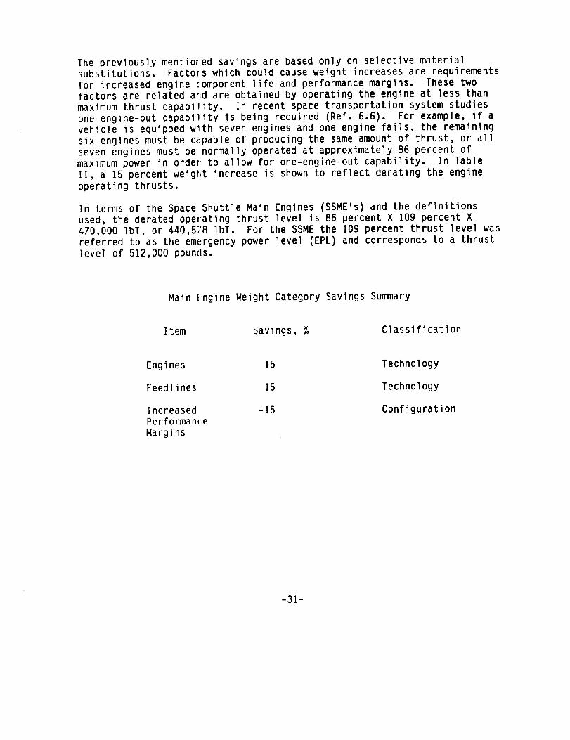
The previously mentiored savings are based only on selective materialsubstitutions. Factors which could cause weight increases are requirementsfor increased engine componentlife and performance margins. These twofactors are related aF_dare obtained by operating the engine at less thanmaximumthrust capability. In recent space transportation system studiesone-engine-out capability is being required (Ref. 6.6). For example, if avehicle is equipped with seven engines and one engine fails, the remainingsix engines must be cepable of producing the sameamount of thrust, or allseven engines must be normally operated at approximately 86 percent ofmaximumpower in order to allow for one-engine-out capability. In TableII, a 15 percent weigP_t increase is shownto reflect derating the engineoperating thrusts.
In terms of the Space Shuttle Main Engines (SSME's) and the definitionsused, the derated operating thrust level is 86 percent X 109 percent X470,000 IbT, or 440,51'8 IbT. For the SSME the 109 percent thrust level was
referred to as the em(_rgency power level (EPL) and corresponds to a thrust
level of 512,000 pounds.
Main Engine Weight Category Savings Summary
Item Savings, % Classification
Engines
Feedlines
Increased
Performan(_e
Margins
15
15
-15
Technology
Technology
Configuration
-31-
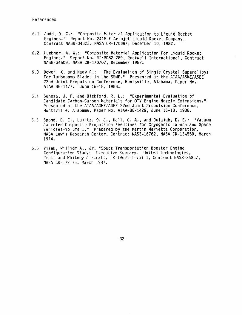
References
6.1
6.2
6.3
6.4
6.5
6.6
Judd, D. C.: "Composite Material Application to Liquid Rocket
Engines." Report No. 2418-F Aerojet Liquid Rocket Company,Contract NAS8-34623, NASA CR-170697, December 10, 1982.
Huebner, A. W.: "Composite Material Application For Liquid RocketEngines." Report No. RI/RD82-289, Rockwell International, Contract
NAS8-34509, NASA CR-170707, December 1982.
Bowen, K. and Nagy P,: "The Evaluation of Single Crystal SuperalloysFor Turbopump Blades in the SSME." Presented at the AIAA/ASME/ASEE
22nd Joint Propulsion Conference, Huntsvi|le, Alabama, Paper No.AIAA-86-1477. June 16-18, 1986.
Suhoza, J. P. and Bickford, R. L.: "Experimental Evaluation of
Candidate Carbon-Carbon Materials for OTV Engine Nozzle Extensions."
Presented at the AIAA/ASME/ASEE 22nd Joint Propulsion Conference,
Huntsville, Alabama, Paper No. AIAA-86-1429, June 16-18, 1986.
Spond, D. E., Laintz, D. J., Hall, C. A., and Dulaigh, D. E.: "VacuumJacketed Composite Propulsion Feedlines for Cryogenic Launch and Space
Vehicles-Volume I." Prepared by the Martin Marietta Corporation.
NASA Lewis Research Center, Contract NAS3-16762, NASA CR-134550, March1974.
Visek, William A., Jr. "Space Transportation Booster EngineConfiguration Study: Executive Summary. United Technologies,
Pratt and Whitney Aircraft, FR-19691-I-Vol 1, Contract NAS8-36857,
NASA CR-179175, March 1987.
-32-

7.0 Reaction Control System (RCS)
The reaction control _,ystem on the Shuttle uses two propellants, monomethy]
hydrazine (MMH) and n trogen tetroxide (N204). On Shuttle II vehicles, LOX
and LH2 have been selected as the baseline propellants for the RCS. These
propellants are common to the ascent and maneuver propulsion systems and
potentially allow for a reduction in the aggregate impulse propellant andreserve and residual propellants through the use of a central propellant
management system. The subsystem weight without any technology
improvements would be heavier than the storable system principally because
the LH2 tanks are far!let and heavier than the storable fuel tanks. Aftercombining advances in technology with inherently heavier system weight, a
zero weight savings is assumed. The overall savings in vehicle weight for
the LOX/LH 2 RCS would appear in the fluids categories in the weight
statement.
Reacti)n Control System Weight Savings Summary
Item ProjectedSavings, %
RCS system (including engines, tanks,
and pressurization and feed systems)
8.0 Orbital Maneuvering System (OMS)
Classification
0 NA
The Shuttle OMS also uses MMH and N204 as propellants. The Shuttle II
vehicle uses cryogenic propellants in its OMS. For the same technology,
these cryogenic systems would tend to be heavier than the storable systemsbecause propellant tanks for the hydrogen and LOX tend to be heavier. Like
the RCS system, combining an inherent increase in the weight of the system
with a decrease by using advanced materials, the weight change of the OMS
system is assumed to be zero for the Shuttle II and 1992 technology
maturity date.
Orbital Manuevering System Weight Savings Savings Summary
Projected
Item Savings, % Classification
OMS system (including engines,
tanks, and pressurization and
feed system)
0 NA
-33-

9.0 Prime Power
The Shuttle uses fuel cells to power the avionics and hydrazine-fueledturbines to drive hydraulic pumpsfor operation of the surface controls,engine gimbals, and other actuators. Currently, the Shuttle (forreliability and safety reasons) uses three fuel cell sets; each set iscapable of delivering 7 kWcontinuously and 12 kWpeak. Four reactantdewar sets are used with the three fuel ceil sets. For similar reliabilityreasons, three auxiliary power units are used; each is capable ofdelivering 63 gal/min of hydraulic fluid at 3,000 psi.
The peak power demandson the Shuttle prime power system occur duringascent and during entry near the terminal area energy management(TEAM)point. The peaks are of short duration.
For the Shuttle II, the present Shuttle fuel cell concept would still beapplied. Available new technology suggests that higher current densitiescould be used to get higher peak powers and effectively increase the powerdeliverable for a given weight of fuel cell (Ref. 9.1). Operating fuelcells at higher current densities reduces life, but the concept could beused to provide emergencypower. In lieu of the hydrazine-powered turbinepumps(referred to as APU's), batteries and electric motors, such as thosedescribed in references 9.1 and 9.2, are proposed for Shuttle II.
By using fuel cells and batteries in lieu of fuel cells and hydraulicpower, greater commonality exists between the two prime power sources.With the fuel cell-battery combination, the batteries can be used primarilyfor the short-term high power demands,whereas the fuel cells can be usedfor the high kilowatt-hour requirements. Both systems could conceivably be"down-sized" by virtue of the ability to recharge "undersized" batteriesusing the fuel cells during off-peak demandperiods and by reducing thenumberof redundant systems in both prime power sources with the knowledgethat either could be relied upon to supply somepower (after properconditioning) in the event of partial failure of one. For furtherredundancy, the fuel cells should be configured so that they could beoperated at muchhigher current densities in an emergency. High voltages,suitable for actuation functions, can also be attained with fuel cells byplacing them in series.
In view of the above (and somewhatarbitrarily), it is assumedthat onethird of the weight of each primary system can be eliminated by virtue ofthe cross-use redundancy strategy and, further, that the two systems can bereduced by 33 percent through new techniques for handling peak power.
Prime power weight is directly affected by the duration of the mission andnumberof crew, the former dictating the numberof kW hrs neededand thelatter principally affecting the size (and power required) for the lifesupport systems. An obvious meansof reducing power requirements istherefore through a reduction in the length of mission and numberof crewneeded.
-34-

Primary Power Weight Savings Summary
Item Projected
Savings, %
Primary power restructuring -- 52
Redundancy through fault
tolerant design applied
to two similar (electrical)
primary power sources (33)
Classification
Technology
Batteries for APU's (28)
Reduced mission (Reduced crew
and days on orbit. Crew of 5 vs7 and 3-day missior vs 7).............. 20 Configuration
References:
9.1 Mullin, J. P. et al.: "The NASA Program In Space Energy ConversationResearch and Technology." Proceedings of the 17th Intersociety -
Energy Conversior Engineering Conference2 Vol. 11, August 1982.
9.2 Swingle, W. L. ar4d Edge, J. T.: "The Electric Orbiter." Proceedinqsof-the IEEE 1981 National Aerospace Electronics Conventionl Dayton,
Ohio, Vol. 1, May 19-21, 1981.
-35-
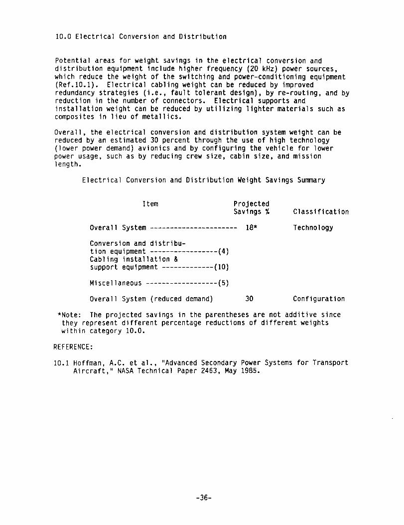
i0.0 Electrical Conversion and Distribution
Potential areas for weight savings in the electrical conversion anddistribution equipment include higher frequency (20 kHz) power sources,which reduce the weight of the switching and power-conditioning equipment(Ref.10.1). Electrical cabling weight can be reduced by improvedredundancy strategies (i.e., fault tolerant design), by re-routing, and byreduction in the numberof connectors. Electrical supports andinstallation weight can be reduced by utilizing lighter materials such ascomposites in lieu of metallics.
Overall, the electrical conversion and distribution system weight can bereduced by an estimated 30 percent through the use of high technology(lower power demand)avionics and by configuring the vehicle for lowerpower usage, such as by reducing crew size, cabin size, and missionlength.
Electrical Conversion and Distribution Weight Savings Summary
Item ProjectedSavings %
Overall System
Conversion and distribu-tion equipmentCabling installation &support equipment
Miscellaneous
Overall System (reduced demand)
(4)
(lO)
(5)
18"
Classification
Technology
30 Configuration
*Note: The projected savings in the parentheses are not additive since
they represent different percentage reductions of different weights
within category 10.0.
REFERENCE:
10.1Hoffman, A.C. et al., "Advanced Secondary Power Systems for Transport
Aircraft," NASA Technical Paper 2463, May 1985.
-36-
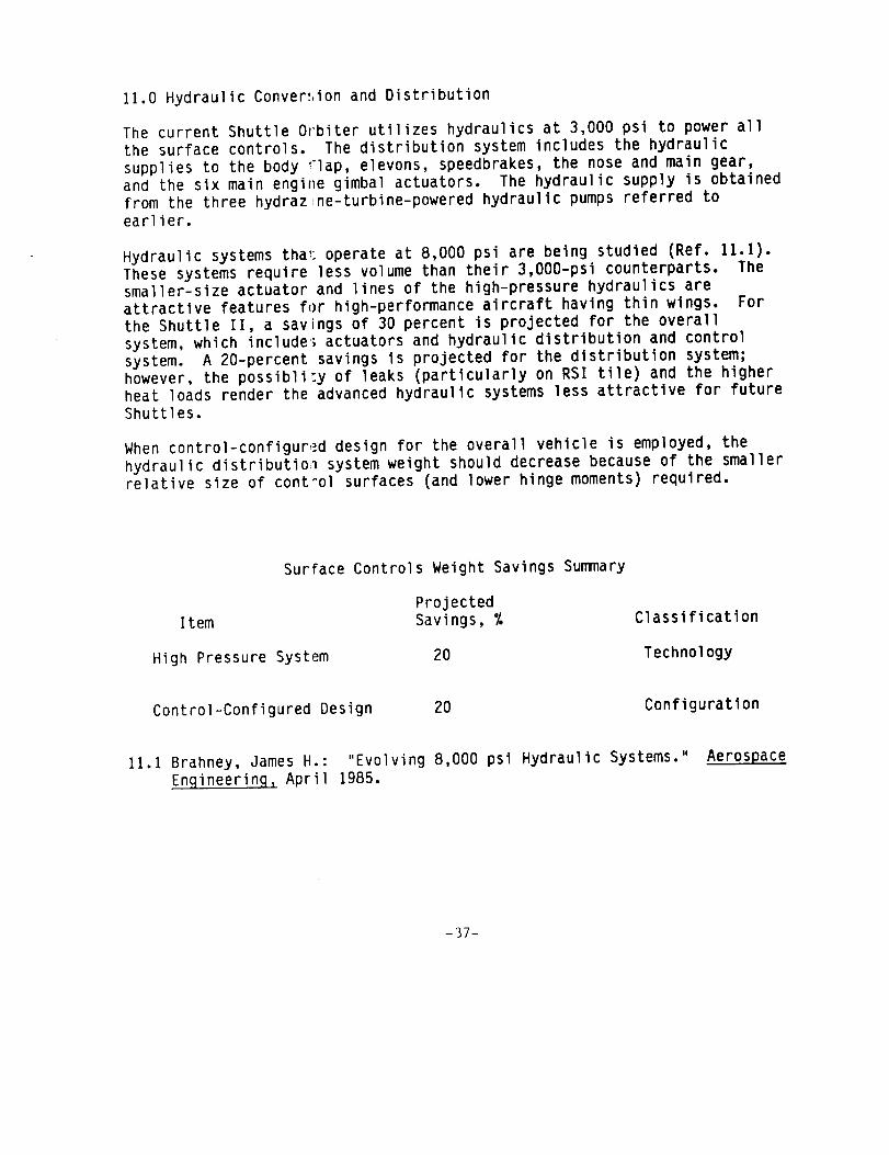
11.0 Hydraulic Conver!,ion and Distribution
The current Shuttle Orbiter utilizes hydraulics at 3,000 psi to power allthe surface controls. The distribution system includes the hydraulicsupplies to the body _lap, elevons, speedbrakes, the nose and main gear,and the six main engine gimbal actuators. The hydraulic supply is obtainedfrom the three hydraz ne-turbine-powered hydraulic pumpsreferred toearlier.
Hydraulic systems tha_ operate at 8,000 psi are being studied (Ref. 11.1).These systems require less volume than their 3,OO0-psi counterparts. Thesmaller-size actuator and lines of the high-pressure hydraulics areattractive features for high-performance aircraft having thin wings. Forthe Shuttle II, a savings of 30 percent is projected for the overallsystem, which include_ actuators and hydraulic distribution and controlsystem. A 20-percent savings is projected for the distribution system;however, the possibli_y of leaks (particularly on RSI tile) and the higherheat loads render the advanced hydraulic systems less attractive for futureShuttles.
Whencontrol-configured design for the overall vehicle is employed, thehydraulic distributio_ system weight should decrease because of the smallerrelative size of control surfaces (and lower hinge moments) required.
SurFace Controls Weight Savings Summary
ProjectedItem Savings, %
High Pressure System 20
Classification
Technology
Control-Configured Design 20 Configuration
11.1Brahney, James H.: "Evolving 8,000 psi Hydraulic Systems." Aerospace
Engineering, April 1985.
-37-

12.0 Surface Controls
In a study of the current Shuttle Orbiter by Edge (Ref. 12.1), an estimated2,656 pounds in weight savings was identified by partially converting fromhydraulic to electric actuators. This weight reduction resulted fromsubstantial savings in primary power supply (batteries instead of APU's forcategory 9.0) and a greatly reduced demandon the environmental controlsystem (category 14.0). Somededicated hydraulic systems were retained.
Table 12-1 represents an estimate of the weight reduction in the ShuttleOrbiter if all actuators are converted to electric. Actuator motorcontrollers are categorized under item 10.0. This category contains theelectrical power control and distribution equipment for the Shuttle and isa logical place for the actuator motor controllers. If charged to theactuator system, the electrical actuators would be an estimated 128 percentheavier rather than 20 percent lighter than hydraulic actuators. TheShuttle hydraulic actuators could be viewed as devices requiring acontinuous supply of energy in the form of a 3,000-psi supply of fluid,whereas electric motors are dormant until receiving a commandfor anactuator deflection. A substantial savings in using the electrical system,however, is in the reduced power and cooling demand,weight savings whichdo not appear in this category.
Table 12-1
Impact of Substituting Electric For Hydraulic Actuators OnThe Shuttle Orbiter
Category Weight Change,% Weight Change, lb
9.0 Prime Power -21 -634
10.0 Electrical Conversion
and Distribution
+13 +1318
11.0 Hydraulic Conversionand Distribution
-I00 -1953
12.0 Surface Controls -20 -568
25.0 Reserve Fluids* -5 -322
26.0 Inflight Losses*
(Hydrazine)
-18 -619
Orbiter Weight Savings 2778 Ib
-38-

12.0 Cont.
A candidate configuralional weight saving item would be a reduction in the
design surface contro _ rates as vehicle size increases, an apparentcharacteristic trend for aircraft. Without this factor, actuator weight
should vary with surface control area to the three halves power. Another
means of reducing wei(lht is to relax the longitudinal static stability
requirements or levels and reduce the size of the control surfaces while
increasing the surface rates. In reference 12.2, by using a dorsal or tipfins in lieu of a verl;ical tail, surfaces needed for directional control
were reduced by approximately two-thirds in area, but directional stabilitylevels were also reduced. In spite of the requirement for increased
control surface rates, a net reduction in actuator weight is projected.
Su'face Control Weight Savings Summary
Projected
Item Savings, % Classification
Actuators
Hydraulic-to-electric 20 Technology
Reduced stability l)vel
(active control)
20 Configuration
Reduced control surface rates with
vehicle size increases
Depends onvehicle size
Configuration
12.1 Edge, J. G. Jr.: "An Electromechanical Actuator TechnologyDevelopment Program." SAE Automotive Engineer Technical Paper No.
1780581, Cherry Hill, North Carolina, April 12, 1978.
12.2 Lepsch, R. A. anJ MacConochie, I. 0.: "Subsonic AerodynamicCharacteristics of a Circular Body Earth-to-Orbit Transport."Presented at the AIAA 4th Applied Aerodynamics Conference, San
Diego, California. Paper No. 86-1801-CP, June 9-11, 1986.
-39-

13.0 Avionics
Substantial weight savings in avionics items are projected for the ShuttleII comparedwith the current Shuttle. Somerelevant studies of lightweightavionics have been reported in references 13.1 and 13.2. Somewhatarbitrarily, a 50-percent weight reduction is projected for a Shuttlevehicle having similar requirements as the current Shuttle. A substantialsavings results from a greatly reduced power and cooling demand, producinga ripple effect on the size and weight of the prime power source and theenvironmental control system. Again, somewhatarbitrarily, a 50-percentreduction in power requirement for the avionics is projected for theShuttle II. The assumptions can be altered when a better definition of thesystems is available. The following represents someof the technologieswhich are projected for use in future shuttles. A savings in crew cabinsize and weight would also be realized through reduced avionics systemvolume requirements. Reducedcrew size also results in reductions indisplays and environmental control system weights. Overall, faulttolerant systems and principles would be applied to eliminate (otherwiserequired) redundant avionics systems.
13.1
13.2
13.3
13.4
Subcategory
Guidance, Navigation, and
Control
Communications and Tracking
Displays and Controls
Instrumentation Systems
New Technology
New inertial measuring unit
New aerosurface amplifier
Global positioning system for TACAN
New technology for S-band
amplifiers and pre-amps
LED multi-functional displays for
individual cathode ray tube
displays
Gallium arsenide for signalconditioner
Avionics Weight Savings Summary
Item
New high technology systemsfor all subcategories
Reduced Crew Size
Projected
Savings, %
50
10
Classification
Technology
Configuration
-40-
Reference
13.1 Canning, T. D.: "Avionics Weight Control For the Starship and
Beyond." A presentation at the 45th annual S.A.W.E., Williamsburg,
Virginia, SAWE Paper No. 1736, May 12-14, 1986.
13.2 Kriegsman, B. A., "Guidance and Navigation System Studies For EntryResearch Vehicles," The Charles Stark Draper Laboratory, Inc.,
Cambridge, Massachusetts. Report No. CSDL-P-2864.
-41-
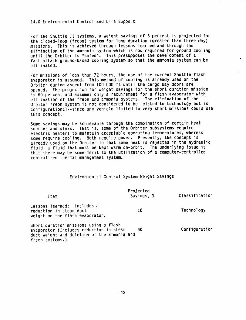
14.0 Environmenta] Control and Life Support
For the Shuttle II systems, a weight savings of 5 percent is projected forthe closed-loop (freon) system for long duration (greater than three day)missions. This is achieved through lessons learned and through theelimination of the ammoniasystem which is now required for ground coolinguntil the Orbiter is "safed". This presupposes the development of afast-attach ground-based cooling system so that the ammoniasystem can beeliminated.
For missions of less than 72 hours, the use of the current Shuttle flashevaporator is assumed. This method of cooling is already used on theOrbiter during ascent from 100,000 ft until the cargo bay doors areopened. The projection for weight savings for the short duration missionis 60 percent and assumesonly a requirement for a flash evaporator withelimination of the freon and ammoniasystems. The e]imination of theOrbiter freon system is not considered to be related to technology but isconfigurationa]--since any vehicle limited to very short missions could use
this concept.
Some savings may be achievable through the combination of certain heatsources and sinks. That is, some of the Orbiter subsystems require
electric heaters to maintain acceptable operating temperatures, whereas
some require cooling. Both require power. Presently, the concept is
already used on the Orbiter in that some heat is rejected in the hydraulicfluid--a fluid that must be kept warm on-orbit. The underlying issue is
that there may be some merit to the utilization of a computer-controlled
centralized thermal management system.
Environmental Control System Weight Savings
ProjectedItem Savings, % Classification
Lessons learned: includes a
reduction in steam duct
weight on the flash evaporator.
10 Technology
Short duration missions using a flash
evaporator (Includes reduction in steam
duct weight and deletion of the ammonia and
freon systems.)
60 Configuration
-42-

15.0 Personnel Provi:_ions
Personnel provisions nclude the food, water, and waste management
systems. Also includ_!d are the fire detection system, the pilot and
mission specialists s1_ations, and airlock provisions. Weight savings are
configuratlonal such as the elimination of the galley. No technology
factors have been applied, although some savings in these provisions should
be available by 1992.
Persor,nel Provisions Weight Savings Summary
Projected
Item Savings, %
Reduced food, waste,
and water management
systems.
40
Classification
Configurational
-43-

Discussion
Potential weight reductions have been identified for Shuttle II
subsystems. For the four years between now and a 1992 launch date, the
projected weight savings for Shuttle II subsystems vary widely. This is
partly a reflection of the wide variance in the research work being
conducted in the various areas and the degree of difficulty. For example,
there is little basis for projecting reductions in large reusable cryogenictanks.
There is, on the other hand, every evidence that large reductions in the
weight of avionics over the current Shuttle will be available by 1992. In
the area of structure, substantial savings are projected. There is
evidence that filament-wound overwraps, pultrusions, and honeycomb
sandwiches made of composites (and bonded) will provide the best prospects
for the lightest Shuttle II. A graph, such as that shown for filament
winding of pressure vessels, is useful for making a prediction for
increased usage of this structural concept (Fig. D-l). The substantial
usage of honeycomb as delineated in this report on the current Shuttle
Orbiter and the increase in its usage in aircraft are also indicators of
the future (Fig. D-2).
The further development of honeycomb sandwich and methods of joining are
important technologies. Two features of metallic honeycomb sandwich thatmake it attractive for Earth-to-orbit transports are low conductivity at
cryogenic temperatures and high conductivity at entry temperatures
(Fig. D-3). At cryogenic temperatures, the honeycomb core acts as both
wall stabilizer and insulator. At elevated temperatures, effective thermal
conductivity is high, and thermal gradients across the sandwich and,
therefore, thermal stresses during entry are minimized. For this latter
reason, honeycomb sandwich makes a good outer surface for a thermal
protection system as well as for a wall on an unprotected tank. The
exponential increase in conductivity versus temperature for honeycomb
sandwich is due to heat transfer by radiation, which is a function of
absolute temperature to the fourth power. On the other hand, the metal and
gas conductivity terms vary nearly linearly with temperature and become
less significant as temperature increases. An underlying issue for
honeycomb sandwich construction is the concern that the covers of the
sandwich may separate when heated if a liquid or gas has been injested into
the honeycomb core. The circumstances of design and installation under
which this might occur need to be further investigated.
-44-

Not evident in the technological and configurational factors listed inTables I and II is the overall weight savings potential through thereduction of power consumption by the use of advanced avionics. Also notevident is the weight reduction which occurs through the use of electricrather than hydraulic actuators. Muchof the savings is the largereduction in prime power and cooling requirements. These potential savingsmight be referred to as subsystem interrelational factors and only become
evident when the vehicle is sized.
Also not included in this report is the weight savings potential through
the reduction in resicual, reserve, and unusable fluids. These fluids
constitute approximat(ly I percent of the vehicle weight at main enginecutoff for the Shuttl('-ET combination. Some reduction in the weight of
these fluids should b(, possible through lessons learned from Shuttle
flights and through the use of new techniques in fluid management such asthe transfer of unused fluids in one system for use in another. (Fluids
can already be transf(_rred between the RCS and OMS systems on the current
Shuttle.)
One of the most signilicant available areas for weight reduction by a 1992
maturity date is in si;ructure; namely, the projections of 5.2% for
technology (Table I) _Lnd 5.0% for configuration (Table II). These
percentages are based on a main engine cutoff (MECO) weight of 321,000 lb.
The MECO weight is derived from the seventh Shuttle flight (FLT7). For
this flight, the orbi:er and external tank (ET) at MECO weighed 240,000 Ib
and 81,000 Ib, respec_:ively, for a total of 321,000 lb. The combined
technological and con_igurational reductions amount to a 32,000 Ib savingsof structure for the current Shuttle /ET combination. The savings for a
single-stage dual fue! vehicle, using the same assumptions, is estimated to
be 44,000 Ib for a vehicle weighing 440,000 lb. at MECO.
The projected reducti,)ns are based on extensive use of composites forstructure and a greatly simplified body shape. The next largest subsystem
weight is the propulsion system, but the emphasis for this subsystem is on
performance and margils, leaving little opportunity to obtain net weight
reductions.
Because of the high c)st per pound of payload to orbit, every pound of
weight saved is important. The counter issues to this argument are the
possible increases in development, manufacturing, and operating costs
brought about by the innovative weight savings features.
-45-

4O
35
ShuttleSRB
I.L'-0",I
30
Composite 25weight
per unit,klb 20
15
Demonstrationrocket motor
15 ft dia x 50 ft IgO Missile
Canister
10
5
01c
1st FilamentWindingMachine Vanguard
Poseidon TricPolaris
O
1955 1965 1975
Year
I1985
Figure D.I Usage of filament wound composites in rocket motors.

I
!
10--
8
Honeycomb 6sandwichrelative
usage 4
2
747 0
m
0L1011
oi I I I I I1950 1955 1960 1965 1970 1975
Year
Figure D.2 Relative usage of honeycomb for aircraft versus year.

I
OOI
15
. 10Effectivethermal
conductivity,_BTUin__
ft 2 hrOR 5
0-500
I I I0 5OO 1000
Mean temperature T M , K
I1500
Figure D.3 Effective thermal conductivity of Ren_ honeycomb panels.
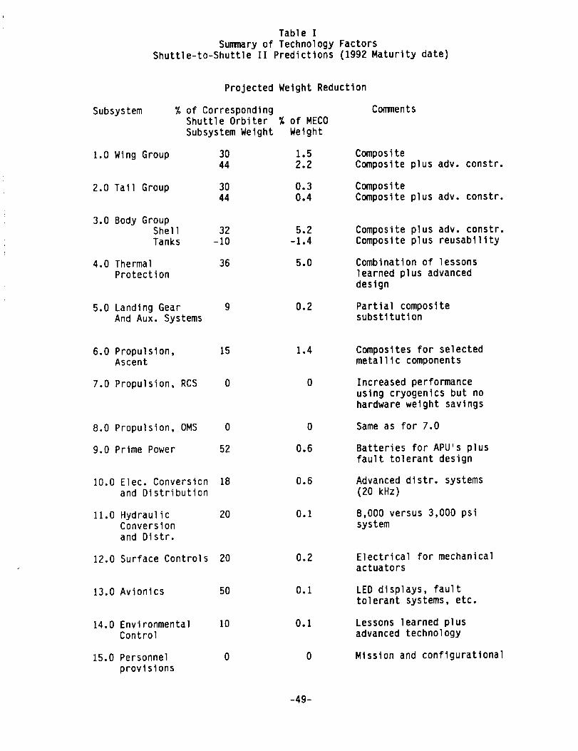
Table I
Summary of Technology FactorsShuttle-to-Shuttle II Predictions (1992 Maturity date)
Projected Weight Reduction
Subsystem % of CorrespondingShuttle Orbiter % of MECO
Subsystem Weight Weight
Comments
1.0 Wing Group 30 1.544 2.2
Composite
Composite plus adv. constr.
2.0 Tail Group 30 0.3
44 0.4CompositeComposite plus adv. constr.
3.0 Body GroupShell
Tanks
32 5.2
-10 -1.4Composite plus adv. constr.
Composite plus reusability
4.0 ThermalProtection
36 5.0 Combination of lessons
learned plus advanceddesign
5.0 Landing GearAnd Aux. Systems
9 0.2 Partial compositesubstitution
6.0 Propulsion,Ascent
7.0 Propulsion, RCS
8.0 Propulsion, OMS
9.0 Prime Power
10.0 Elec. Conversionand Distribution
11.0 HydraulicConversion
and Distr.
12.0 Surface Controls 20
15 1.4
O 0
0 0
52 0.6
18 0.6
20 0.1
0.2
13.0 Avionics 50 0.1
14.0 Environmental 10Control
15.0 Personnel 0
provisions
0.1
0
Composites for selectedmetallic components
Increased performance
using cryogenics but nohardware weight savings
Same as for 7.0
Batteries for APU's plus
fault tolerant design
Advanced distr, systems
(20 kHz)
8,000 versus 3,000 psi
system
Electrical for mechanicalactuators
LED displays, fault
tolerant systems, etc.
Lessons learned plusadvanced technology
Mission and configuratlonal
-49-
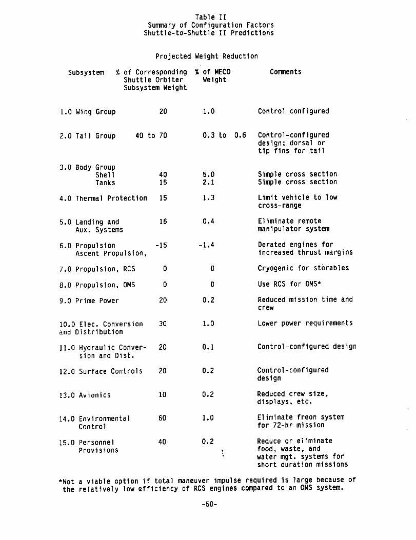
Table IISummaryof Configuration Factors
Shuttle-to-Shuttle II Predictions
Subsystem
Projected Weight Reduction
% of Corresponding %of MECOShuttle Orbiter WeightSubsystemWeight
Comments
1.0 WingGroup 20 1.0 Control configured
2.0 Tail Group 40 to 70 0.3 to 0.6 Control-configured
design; dorsal ortip fins for tail
3.0 Body GroupShell 40 5.0Tanks 15 2.1
Simple cross section
Simple cross section
4.0 Thermal Protection 15 1.3 Limit vehicle to low
cross-range
5.0 Landing and 16 0.4
Aux. Systems
Eliminate remote
manipulator system
6.0 PropulsionAscent Propulsion,
7.0 Propulsion, RCS
-15 -1.4
0 0
Derated engines for
increased thrust margins
Cryogenic for storables
8.0 Propulsion, OMS
9.0 Prime Power
0 0
20 0.2
Use RCS for OMS*
Reduced mission time and
crew
10.0 Elec. Conversion
and Distribution
30 1.0 Lower power requirements
11.0 Hydraulic Conver-sion and Dist.
20 O.I Control-configured design
12.0 Surface Controls 20 0.2 Control-configured
design
13.0 Avionics 10 0.2 Reduced crew size,
displays, etc.
14.0 Environmental 60 1.0Control
Eliminate freon systemfor 72-hr mission
15.0 Personnel 40 0.2
Provisions
Reduce or eliminate
food, waste, and
water mgt. systems forshort duration missions
*Not a viable option if total maneuver impulse required is large because ofthe relatively low efficiency of RCS engines compared to an OM5 system.
-50-

Summary Remarks
Weight reductions for Shuttle II subsystems are projected using thepresent Shuttle Orbiter and External Tank as a baseline. Potential savingsare categorized as related to technology or configuration. The weightsavings projected for a 1992 technology maturity date vary widely fromsubsystem to subsystem, but the greatest potential for overall reduction inthe vehicle weight appears to be in the body shell and thermal protectionsystems. Weight reductions are projected in the body shell throughsimplified configurat'on and high technology materials and fabricationmethods, and in the thermal protection system, through lessons learned andthe ability to select-vely reduce thermal protection system thickness. Nosubstantial weight savings are projected for main propellant tanks for the1992 maturity date pr ncipally because of the reusability feature requiredand the lack of research in large tanks to support any projections forweight reduction. Also, no substantial weight savings are projected formain rocket engines p_rtly because of the increased performance marginsbeing required. Some weight reductions are projected for other subsystems,but the overall savings are small because of the relatively small size ofmost of the subsystems; when compared to the total vehicle weight.
Strong advocacy is given for the further development of honeycomb forairframes, heat shield elements, and propellant tank walls. Filamentwinding and pu]trusion manufacturing methods, using composites, are alsostrongly advocated in order to achieve the weight goals for a Shuttle II.These technologies are considered favorable in that they are projected tobe mature enough by I!)92 for use in primary and secondary structures. Theextensive use of hone3comb sandwich construction in the current ShuttleOrbiter is cited as a basis for its more extensive use in Shuttle II.
When all the technolo!ly factors are summed, the projected weight reductionis approximately 16 percent of the vehicle weight at main engine cutoff.When the configurational factors are summed, the projected weightreduction is 12 percent. In reality, the projected weight reductions aregreater for the follo_ving reasons: Firstly, the projected reductions inweight do not include potential savings by employing a scavenging system torecover otherwise unusable fluids. The potential for weight reduction isan additional 2 percent of vehicle weight based on and assumption of 60percent recovery of t;le fluids present, but unused, at main engine cutoff.Secondly, the 16 and t2 percent figures for technology and configurationfactors become 18 and 13.5, respectively, at engine cutoff if the weight ofthe payload is not included. Thirdly, the overall reductions projected arethe result of algebraic addition of savings for each subsystem. When theindividual reductions are combined in a computer driven sizing program, theoverall reductions are even greater because of the beneficial effect of theweight reduction of o le subsystem on the other subsystems. Based on theabove, a savings of 2] to 25 percent is considered achievable through theapplication of technologies available by 1992. The savings throughconfigurati( percentage reduction depending uponthe extent other subsystems are simplified or
reduced in capacity.
-51-
1, Report No, 2. Government Accession No,
NASA '1'M-89116
4 Talle and Subtitle
Sh,ltt I(' 't'(_ Slmtt le I I: Subsystem Weight Reduction
Pot ent in l (l",,_t imated 1992 Tc('hno]ogy Readiness Date)
7 Author(s)
Inn (), Ha('( ono('h i(,
9 Performing Organization Name and Address
NASA I,;lnf, ,]('y Resenr('h Center
Ihlmpt (m, VA 23665-5225
12 Slxmsoring Agency Name and Address
N;it i(mn] Aeronautics and Space Administration
W;I,'_h in vt ,:n, 1)(: 2054()-000I
3. Recipient's Catalog No.
5. Report Date
Hay 1988
6. Performing Organization Code
8. Performing Organization Report No.
10. Work Unit No.
906-65-05-0 l
11. Contract or Grant No.
13. Type of Report and Period Covered
Technical Memorandum
14. Sponsoring Agency Code
5. Supplementary Notes
,G A_,?_ objective of this study was to make estimates of the weight savings
that might be realized on all the subsystems on an advanced rocket-powered
Shuttle (designated Shuttle II) by using advanced technologies having aprojected maturity date of 1992. The current Shuttle with external tank
was used as a baseline from which to make estimates of weight savings oneach subsystem.
The subsystems with the greatest potential for weight reduction are the
body shell and the thermal protection system. For the body shell, a
reduction of 5.2 percent in the weight of the vehicle at main engine cutoff
is projected through the application of new technologies, and an additional
configuration-based reduction of 5 percent is projected through
simplification of body shape. A reduction of 5 percent is projected for
the thermal protection system through experience with the current SpaceShuttle a_the potential for reducing thermal protection system thicknesses
in selected areas. Main propellant tanks are expected to increase slightlyin weight. The main propulsion system is also projected to increase in
weight because of the requirement to operate engines at derated power
levels in order to accommodate one-engine-out capability. The projections
for weight reductions through improvements in the remaining subsystems are
relatively small. By summing all the technology factors, a projected
reduction of 16 percent in the vehicle weight at main engine cutoff is
obtained. By summarizing the configurationa] factors, a potential
reduction of 12 percent in vehicle weight is obtained.
11 Key Words (Suggested by Author(s)) 18. Distribution Statement
Shlitt Ic
W(, i}_tlt ::Rcdu('t i(,,, ORIGINAL PAGB IS
I'()tcnt i;)l OF POOR QUALIT_Subject Category 16
19 ,qecuray Classif. (of th*s report)
ll|w lass i f ied
20 Security Classif. (of this page)
Ilnc l assi f ied
21. No. of Pages
53
22. Price