Embed Size (px)
Citation preview

SHUTTLE BUS CHASSIS MAINTENANCE MANUAL
Models: FB65MB45MB55XB
STI-472 (8/05P) Published byFreightliner LLC
4747 N. Channel Ave.Portland, OR 97217
Printed in U.S.A.

ForewordScheduled maintenance provides a key element for safe operation of your vehicle. A propermaintenance program also helps to minimize downtime and to safeguard warranties. Thismaintenance manual provides information necessary for years of safe, reliable, and cost-efficientvehicle operation.
Perform daily pre-trip inspection and maintenance as outlined in the vehicle operator’s manual.Perform the operations in this maintenance manual at scheduled intervals based upon distancetraveled or months of operation. Your authorized servicing dealer has the qualified techniciansand equipment to perform this maintenance for you. Your dealership can also set up a scheduledmaintenance program tailored specifically to your needs. Optionally, your dealership can assistyou in learning how to perform the maintenance procedures in this manual.
IMPORTANT: Descriptions and specifications in this manual were in effect at the time ofprinting. Freightliner Custom Chassis Corporation (FCCC) reserves the right to discon-tinue models, and to change specifications or design at any time without notice andwithout incurring obligation. Descriptions and specifications contained in this publicationprovide no warranty, expressed or implied, and are subject to revision and editionswithout notice.
For additional information, please contact Freightliner LLC, Service Systems and Documenta-tion, P.O. Box 3849, Portland, OR 97208-3849, U.S.A., or refer to http://www.Freightliner.comand http://www.FreightlinerChassis.com.
Environmental Concerns and RecommendationsWhenever you see instructions in this manual to discard materials, you should attempt to reclaimand recycle them. To preserve our environment, follow appropriate environmental rules andregulations when disposing of materials.
NOTICE: Parts Replacement ConsiderationsDo not replace suspension, axle, or steering parts (such as springs, wheels, hubs, and steeringgears) with used parts. Used parts may have been subjected to collisions or improper use andhave undetected structural damage.
© 2000-2005 Freightliner LLC
All rights reserved. No part of this publication, in whole or in part, may be translated, reproduced,stored in a retrieval system, or transmitted in any form by any means, electronic, mechanical,photocopying, recording, or otherwise, without the prior written permission of Freightliner LLC.
Freightliner LLCService Systems and Documentation (POC-SSD)
P.O. Box 3849Portland, OR 97208–3849
Freightliner LLC distributes the following major service publications.
Workshop/ServiceManual
Workshop/service manuals contain service and repair information for all vehiclesystems and components, except for major components such as engines, trans-missions, and rear axles. Each workshop/service manual section is divided intosubjects that can include general information, principles of operation, removal,disassembly, assembly, installation, specifications, and troubleshooting.
Maintenance Manual Maintenance manuals contain routine maintenance procedures and intervals forvehicle components and systems. They have information such as lubricationprocedures and tables, fluid replacement procedures, fluid capacities, specifica-tions, procedures for adjustments and for checking the tightness of fasteners.Maintenance manuals do not contain detailed repair or service information.
Operator’s Manual Driver’s/operator’s manuals contain information needed to enhance the driver’sunderstanding of how to operate and care for the vehicle and its components.Each manual contains a chapter that covers pretrip inspection and daily mainte-nance of vehicle components. Driver’s/operator’s manuals do not contain de-tailed repair or service information.
Parts Technical Manual Freightliner LLC publishes this manual to aid in the identification of serviceablereplacement vehicle parts. This manual is used in conjunction with the partsbook and the service parts catalog microfiche.
Service Bulletins Service Bulletins provide the latest service tips, field repairs, product improve-ments, and related information. Some service bulletins are updates to informa-tion in the workshop/service manual. These bulletins take precedence overworkshop/service manual information, until the latter is updated; at that time, thebulletin is usually canceled. The service bulletins manual is available only todealers. When doing service work on a vehicle system or part, check for a validservice bulletin for the latest information on the subject.
IMPORTANT: Before using a particular service bulletin, check the currentservice bulletin validity list to be sure the bulletin is valid.
Recall Bulletins These bulletins pertain to special situations that involve service work or replace-ment of parts in connection with a recall notice. Recall bulletins pertain to mat-ters of vehicle safety. All bulletins are distributed to dealers; customers receivenotices that apply to their vehicles.
Field ServiceModifications
This publication is concerned with non-safety-related service work or replace-ment of parts. All field service modifications are distributed to dealers; custom-ers receive notices that apply to their vehicles.
IntroductionDescriptions of Service Publications
Shuttle Bus Chassis Maintenance Manual, December 2002 I–1
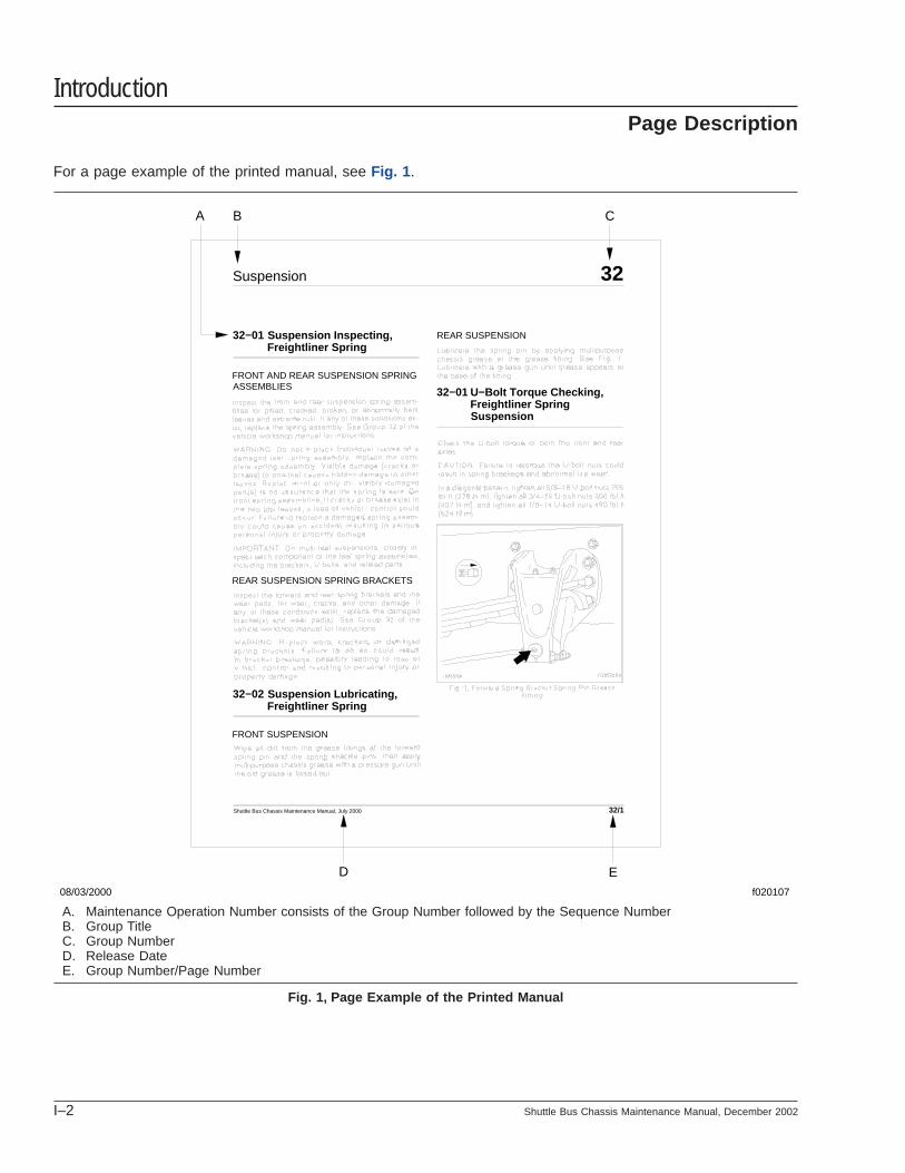
For a page example of the printed manual, see Fig. 1 .
f020107
A B C
D E
32Suspension
Suspension Inspecting,Freightliner Spring
32−01
U−Bolt Torque Checking,Freightliner Spring
32−01
Suspension
Suspension Lubricating,Freightliner Spring
32−02
FRONT AND REAR SUSPENSION SPRINGASSEMBLIES
FRONT SUSPENSION
REAR SUSPENSION
Shuttle Bus Chassis Maintenance Manual, July 2000 32/1
REAR SUSPENSION SPRING BRACKETS
08/03/2000
A. Maintenance Operation Number consists of the Group Number followed by the Sequence NumberB. Group TitleC. Group NumberD. Release DateE. Group Number/Page Number
Fig. 1, Page Example of the Printed Manual
IntroductionPage Description
I–2 Shuttle Bus Chassis Maintenance Manual, December 2002

Group No. Group Title
00 . . . . . . . . . . . . . . . . . . . . . . General Information01 . . . . . . . . . . . . . . . . . . . . . . . . . . . . . . . . Engine09 . . . . . . . . . . . . . . . . . . . . . . . . . . . . . . Air Intake13 . . . . . . . . . . . . . . . . . . . . . . . . . Air Compressor15 . . . . . . . . . . . . . . . . . . . Alternators and Starters20 . . . . . . . . . . . . . . . . . . . Engine Cooling/Radiator26 . . . . . . . . . . . . . . . . . . . . . . . . . . . Transmission31 . . . . . . . . . . . . . Frame and Frame Components32 . . . . . . . . . . . . . . . . . . . . . . . . . . . . Suspension33 . . . . . . . . . . . . . . . . . . . . . . . . . . . . . Front Axle35 . . . . . . . . . . . . . . . . . . . . . . . . . . . . . Rear Axle40 . . . . . . . . . . . . . . . . . . . . . . . . Wheels and Tires41 . . . . . . . . . . . . . . . . . . . . . . . . . . . . . . Driveline42 . . . . . . . . . . . . . . . . . . . . . . . . . . . . . . . . Brakes46 . . . . . . . . . . . . . . . . . . . . . . . . . . . . . . . Steering47 . . . . . . . . . . . . . . . . . . . . . . . . . . . . . . . . . Fuel49 . . . . . . . . . . . . . . . . . . . . . . . . . . . . . . . Exhaust54 . . . . . . . . . . Electrical, Instruments, and Controls83 . . . . . . . . . . . . . . . . . Heater and Air Conditioner
IntroductionMaintenance Manual Contents
Shuttle Bus Chassis Maintenance Manual, December 2002 I–3

Title of Maintenance Operation (MOP) MOP Number
Determining Scheduled Maintenance Intervals. . . . . . . . . . . . . . . . . . . . . . . . . . . . . . . . . . . . . . . . . . . . . 00–01
Initial Maintenance IM Operations. . . . . . . . . . . . . . . . . . . . . . . . . . . . . . . . . . . . . . . . . . . . . . . . . . . . . . 00–06
Lubrication and Fluid Level Check . . . . . . . . . . . . . . . . . . . . . . . . . . . . . . . . . . . . . . . . . . . . . . . . . . . . . 00–04
M1 Maintenance Interval Operations. . . . . . . . . . . . . . . . . . . . . . . . . . . . . . . . . . . . . . . . . . . . . . . . . . . . 00–07
M2 Maintenance Interval Operations. . . . . . . . . . . . . . . . . . . . . . . . . . . . . . . . . . . . . . . . . . . . . . . . . . . . 00–08
M3 Maintenance Interval Operations. . . . . . . . . . . . . . . . . . . . . . . . . . . . . . . . . . . . . . . . . . . . . . . . . . . . 00–09
Maintenance Interval Table. . . . . . . . . . . . . . . . . . . . . . . . . . . . . . . . . . . . . . . . . . . . . . . . . . . . . . . . . . . 00–03
Maintenance Operation Sets. . . . . . . . . . . . . . . . . . . . . . . . . . . . . . . . . . . . . . . . . . . . . . . . . . . . . . . . . . 00–05
Metric/U.S. Customary Conversion Table. . . . . . . . . . . . . . . . . . . . . . . . . . . . . . . . . . . . . . . . . . . . . . . . . 00–12
Noise Emission Controls Maintenance. . . . . . . . . . . . . . . . . . . . . . . . . . . . . . . . . . . . . . . . . . . . . . . . . . . 00–10
Torque Specifications Tables. . . . . . . . . . . . . . . . . . . . . . . . . . . . . . . . . . . . . . . . . . . . . . . . . . . . . . . . . . 00–13
Vehicle Maintenance Schedule Table . . . . . . . . . . . . . . . . . . . . . . . . . . . . . . . . . . . . . . . . . . . . . . . . . . . 00–02
Verification of Inspections Log. . . . . . . . . . . . . . . . . . . . . . . . . . . . . . . . . . . . . . . . . . . . . . . . . . . . . . . . . 00–11
General Information 00Index, Alphabetical
Shuttle Bus Chassis Maintenance Manual, August 2005

DescriptionCategory I (urban transport) applies to vehicles thatannually travel up to 20,000 miles (32 000 kilome-ters).
Category II (rural transport) applies to vehicles thatannually travel over 20,000 miles (32 000 kilome-ters).
The table under Vehicle Maintenance Schedule Tableshows the two categories of vehicle usage. For eachcategory, the appropriate distance and time intervalsare given for performing initial maintenance and forrepeating each maintenance operation set (M1through M3).
The table under Maintenance Interval Table showswhich maintenance operation set must be performedat the actual distances (miles and kilometers) or ac-tual months of operation for each maintenance cat-egory. The schedule of actual distances (andmonths) is based on the intervals given in the Ve-hicle Maintenance Schedule Table.
The table under Maintenance Operation Sets lists, innumerical order, the text reference numbers and de-scriptions of all maintenance operations, and indi-cates all maintenance operation sets at which eachoperation must be performed.
Each Maintenance Interval Operations table (IMthrough M3) lists the appropriate text reference num-bers and descriptions of only those maintenance op-erations that must be performed at that maintenanceoperation set. Each maintenance operation set islisted in a separate Maintenance Interval Operationstable.
UseBefore placing your new vehicle in service, determinethe maintenance category (Category I or II) that ap-plies to your intended use of the vehicle. See theVehicle Maintenance Schedule Table to determinethe distance (or time) interval at which each mainte-nance operation set must be performed for your cat-egory of vehicle.
When the vehicle reaches the actual distance (ormonths) given for an interval, see the MaintenanceInterval Table to find the maintenance operation setthat applies to that interval. Then perform the mainte-nance operations listed in the applicable Mainte-nance Interval Operations table. Use the mainte-
nance operation reference numbers to findinstructions in the manual for completion of each op-eration.
Complete each maintenance operation set at the re-quired interval. Then, when you have completedmaintenance operation set M3 under the 12th Main-tenance Number listed in the Maintenance IntervalTable, repeat the pattern. The 13th MaintenanceNumber will begin at maintenance operation set M1,under the 1st Maintenance Number listed in theMaintenance Interval Table.
NOTE: When performing operations for the 13thMaintenance Number, complete the M1 opera-tions only, not the Initial Maintenance opera-tions.
To determine the distance/months for the 13th Main-tenance Number, add your category’sdistance/months for the 1st Maintenance Number tothe distance/months for the 12th Maintenance Num-ber, then perform the operations listed in the appli-cable table in the Maintenance Interval Operationstables. For the 14th Maintenance Number, add thedistance/months for the 2nd to the distance/monthsfor the 12th; continue this pattern for each succes-sive Maintenance Number.
General Information 00Determining Scheduled Maintenance Intervals: 00–01
Shuttle Bus Chassis Maintenance Manual, August 2005 00/1

Vehicle Maintenance Schedule Table
Vehicle Maintenance Schedule Table
Description Maintenance Operation SetMaintenance Intervals
Frequency Miles km Months
CATEGORY I(Urban Transport)
vehicles that annually travel up to20,000 miles (32 000 km)
Initial Maintenance (IM) first 2500 4000 3
Maintenance 1 (M1) every 2500 4000 3
Maintenance 2 (M2) every 10,000 16 000 12
Maintenance 3 (M3) every 30,000 48 000 36
CATEGORY II(Rural Transport)
vehicles that annually travel over 20,000miles (32 000 km)
Initial Maintenance (IM) first 5000 8000 3
Maintenance 1 (M1) every 5000 8000 3
Maintenance 2 (M2) every 20,000 32 000 12
Maintenance 3 (M3) every 60,000 96 500 36
General Information00Vehicle Maintenance Schedule Table: 00–02
Shuttle Bus Chassis Maintenance Manual, August 200500/2

Maintenance Interval Table
Maintenance Interval Table
Maint. No. Maint. Oper.Set
Category I Category II
miles x 100 km x 100 months miles x 100 km x 100 months
1st IM + M1 25 40 3 50 80 3
2nd M1 50 80 6 100 160 6
3rd M1 75 120 9 150 240 9
4th M2 100 160 12 200 320 12
5th M1 125 200 15 250 400 15
6th M1 150 240 18 300 480 18
7th M1 175 280 21 350 560 21
8th M2 200 320 24 400 640 24
9th M1 225 360 27 450 720 27
10th M1 250 400 30 500 800 30
11th M1 275 440 33 550 885 33
12th M3 300 480 36 600 965 36
General Information 00Maintenance Interval Table: 00–03
Shuttle Bus Chassis Maintenance Manual, August 2005 00/3

Lubrication and Fluid Level Check
MaintenanceOperationReferenceNumber
Maintenance Operation Description
26–02 Transmission Fluid and Filter Changing
26–03 Transmission Fluid Level Checking
32–02 Suspension Lubricating, Freightliner Spring
33–01 Knuckle Pin Lubricating
33–02 Tie-Rod End Lubricating
33–05 Oil-Filled Hubs Oil Level Checking
33–06 Oil-Filled Hubs Oil Changing
33–07 Wheel Bearing Removing, Cleaning, Checking, Repacking, andAdjusting
35–01 Axle Lubricant Level Checking
35–02 Axle Lubricant Changing and Magnetic Plug Cleaning
41–01 Driveline Inspecting and Lubricating
42–04 Air Reservoir Automatic Drain Valve Disassembling, Cleaning, andInspecting, Bendix DV–2
42–05 Automatic Slack Adjuster Lubricating and Checking, Meritor
42–09 Camshaft Bracket Bushing Lubricating
42–10 Foot Brake valve Actuator Lubricating, Bendix E–6
42–12 Brake Caliper Slide Rail Lubricating, Bosch Hydraulic Brakes*
42–13 Brake Caliper Slide Pin Lubricating, Bosch Hydraulic Brakes
42–15 Drum Brake Shoe Roller Lubricating
46–01 Steering Driveline Lubricating
46–02 Drag Link Lubricating
46–03 Power Steering Reservoir Fluid Level Checking
46–04 Power Steering Reservoir Fluid and Filter Changing
46–05 Steering Gear Lubricating
54–03 Ground Cables Checking and Cleaning* IMPORTANT: Lubricate every 6 months "or" every 18,000 miles (28 800 km), whichever comes first.
Table 1, Lubrication and Fluid Level Check
General Information00Lubrication and Fluid Level Check: 00–04
Shuttle Bus Chassis Maintenance Manual, August 200500/4

NOTE: Maintenance operations appearing in italics inthis table are for noise emission control components.Numbers in this table are maintenance operation ref-
erence numbers matching those in the text of thismanual.
REQUIRED MAINTENANCE OPERATION SET IM M1 M2 M3
Maintenance Operation Reference Number and Maintenance Operation
00–04 Lubrication and Fluid Level Check • • • •
01–01 Engine-Support Fasteners Checking •
01–02 Engine Drive Belt Inspecting • • • •
01–03 Pacbrake Inspecting and Maintenance*
09–01 Air Cleaner Element Inspecting and Replacing • •
09–02 Air Intake System Inspecting • • • •
13–01 Air Compressor Inspecting • • • •
15–01 Alternator, Battery, and Starter Checking • •
20–01 Radiator Cap Checking • •
20–02 Radiator Pressure Flushing and Coolant Changing •
20–03 Eaton Viscous Fan Drive Checking • •
26–01 Transmission Breather Checking • •
26–02 Transmission Fluid and Filter Changing† •
26–03 Transmission Fluid Level Checking • • • •
31–01 Frame Fastener Torque Checking • •
32–01 Suspension Inspecting, Freightliner Spring • • • •
32–02 Suspension Lubricating, Freightliner Spring • • • •
32–03 U-Bolt Torque Checking, Freightliner Spring • •
32–04 Spring Bracket Fastener Torque Checking, Freightliner Spring (Rear) • •
32–05 Fastener Torque Checking, Freightliner AirLiner • •
32–06 Component Clearance Checking, Freightliner AirLiner • •
32–07 Component Inspecting and Operation Checking, Freightliner AirLiner •
32–08 U-Bolt Torque Checking, Freightliner AirLiner • •
32–09 Shock Absorber Checking, Freightliner Spring •
32–10 Torque Arm Bushing Checking, Freightliner AirLiner • • • •
32–11 Suspension Inspecting, Neway • •
33–01 Knuckle Pin Lubricating • • • •
33–02 Tie-Rod End Lubricating • • • •
33–03 Tie-Rod End Inspecting • • • •
33–04 Wheel Alignment Checking, Front Axle •
33–05 Oil-Filled Hubs Oil Level Checking • • • •
33–06 Oil-Filled Hubs Oil Changing •
33–07 Wheel Bearing Removing, Cleaning, Checking, Repacking, and Adjusting •
General Information 00Maintenance Operation Sets: 00–05
Shuttle Bus Chassis Maintenance Manual, August 2005 00/5

REQUIRED MAINTENANCE OPERATION SET IM M1 M2 M3
Maintenance Operation Reference Number and Maintenance Operation
35–01 Axle Lubricant Level Checking • • • •
35–02 Axle Lubricant Changing and Magnetic Plug Cleaning • •
35–03 Axle Breather Checking • • • •
40–01 Wheel Nut and Rim Nut Checking • • • •
41–01 Driveline Inspecting and Lubricating • • • •
42–01 Air Dryer Checking, Bendix AD–9‡ • •
42–02 Air Dryer Desiccant Replacing, Bendix AD–9 •
42–03 Air Dryer Inspecting, Bendix AD–9‡ • • •
42–04 Air Reservoir Automatic Drain Valve Disassembling, Cleaning, and Inspecting,Bendix DV–2 • •
42–05 Automatic Slack Adjuster Lubricating and Checking, Meritor • • • •
42–06 Bendix Hydro-Max Power Booster Checking • • • •
42–07 Brake Lines Checking, Hydraulic Disc Brakes • • • •
42–08 Brake Lining Wear Checking, Hydraulic Disc Brakes • • • •
42–09 Camshaft Bracket Bushing Lubricating • •
42–10 Foot Brake Valve Actuator Lubricating, Bendix E–6 • • •
42–11 Relay Valve Checking, Midland • • • •
42–12 Brake Caliper Slide Rail Lubricating, Bosch Hydraulic Brakes§ • • • •
42–13 Brake Caliper Slide Pin Lubricating, Bosch Hydraulic Brakes¶
42–14 ABS Tone Rings Cleaning** • • • •
42–15 Drum Brake Shoe Roller Lubricating • •
42–16 Air Dryer Inspecting, Midland • • •
42–17 Air Dryer Desiccant and Coalescent Filter Replacing, Midland††
46–01 Steering Driveline Lubricating • • • •
46–02 Drag Link Lubricating • • • •
46–03 Power Steering Reservoir Fluid Level Checking • • • •
46–04 Power Steering Reservoir Fluid and Filter Changing •
46–05 Steering Gear Lubricating • • • •
47–01 Diesel Fuel Tank Draining and Vent Checking • • • •
47–02 CNG Low-Pressure Fuel Filter Draining • • • •
47–03 CNG High-Pressure Fuel Filter Draining • • • •
47–04 Fuel/Water Separator Element Replacing • •
47–05 CNG Fuel Block Housing Draining • • • •
47–06 CNG Fuel Leak Testing • • • •
47–07 CNG Fuel Tank Visual Inspecting‡‡ • • • •
47–08 CNG High-Pressure Fuel Filter Replacing • • • •
General Information00Maintenance Operation Sets: 00–05
Shuttle Bus Chassis Maintenance Manual, August 200500/6

REQUIRED MAINTENANCE OPERATION SET IM M1 M2 M3
Maintenance Operation Reference Number and Maintenance Operation
47–09 CNG Low-Pressure Fuel Filter Replacing • • • •
47–10 Inline Fuel Strainer Replacing, Cummins ISB02 Engine • •
49–01 Exhaust System Inspecting • •
54–01 Coolant Level Sensor Cleaning •
54–02 Electrical System Checking • •
54–03 Ground Cables Checking and Cleaning • •
83–01 Air Conditioning Checking, R-134a Refrigerant System • • • •* With frequent use, the Pacbrake Exhaust Brake will operate free of maintenance. However, if the vehicle is used inconsistently, seasonally, or is exposed to
excess moisture, it will be necessary to perform preventative maintenance as instructed in Maintenance Operation 01–03 .† For series 1000/2000/2400 transmissions with non-TranSynd ATF, change oil and filters at 50,000 miles (80 000 km) or 24 months, whichever comes first.‡ Perform annually during the fall.§ IMPORTANT: Lubricate every 6 months "or" every 18,000 miles (28 800 km), whichever comes first.¶ See the "Bosch Pin Slide Disc Brakes Service Manual" for more information.** This operation applies specifically to vehicles used during winter months in areas where corrosive materials are used on the highways.†† Replace the desiccant and coalescent filter every 18,000 miles (30 000 km) or every 18 months.‡‡ Visually inspect the fuel tank every 25,000 miles (40 000 km) OR every 6 months, whichever comes first. The fuel tank must be replaced every 15 years.
General Information 00Maintenance Operation Sets: 00–05
Shuttle Bus Chassis Maintenance Manual, August 2005 00/7

This Initial Maintenance IM Operations table lists allmaintenance operations that are to be performed atinitial maintenance (IM). Numbers in this table aremaintenance operation reference numbers matchingthose in the text of this manual, that can be used to
find detailed instructions for the operations to be per-formed. All operations listed in the table, along withthe operations listed in the M1 Maintenance IntervalOperations table, must be performed to complete theinitial maintenance (IM).
Initial Maintenance (IM) Operations
Maint. Oper.No. Initial Maintenance (IM) Operations
00–07 Perform all M1 Operations
31–01 Frame Fastener Torque Checking
32–03 U-Bolt Torque Checking, Freightliner Spring
32–04 Spring Bracket Fastener Torque Checking, Freightliner Spring (Rear)
32–05 Fastener Torque Checking, Freightliner AirLiner
32–06 Component Clearance Checking, Freightliner AirLiner
32–08 U-Bolt Torque Checking, Freightliner AirLiner
32–11 Suspension Inspecting, Neway
33–04 Wheel Alignment Checking, Front Axle
35–02 Axle Lubricant Checking and Magnetic Plug Cleaning
42–03 Air Dryer Inspecting, Bendix AD–9
42–10 Foot Brake Valve Actuator Lubricating, Bendix E–6
42–12 Brake Caliper Slide Rail Lubricating, Bosch Hydraulic Brakes
42–16 Air Dryer Inspecting, Midland
General Information00Initial Maintenance IM Operations: 00–06
Shuttle Bus Chassis Maintenance Manual, August 200500/8

This M1 Maintenance Interval Operations table listsall maintenance operations that are to be performedat the M1 maintenance interval. Numbers in thistable are maintenance operation reference numbers
matching those in the text of this manual, that can beused to find detailed instructions for the operations tobe performed.
M1 Maintenance Interval Operations
Maint.Oper. No. M1 Maintenance Interval Operations
00–04 Lubrication and Fluid Level Check (includes the following)
• Transmission Fluid Level Checking
• Suspension Lubricating, Freightliner Spring
• Knuckle Pin Lubricating
• Tie-Rod End Lubricating
• Oil-Filled Hubs Oil Level Checking
• Axle Lubricant Level Checking
• Driveline Inspecting and Lubricating
• Automatic Slack Adjuster Lubricating and Checking, Meritor
• Brake Caliper Slide Rail Lubricating, Bosch Hydraulic Brakes
• Steering Driveline Lubricating
• Drag Link Lubricating
• Power Steering Reservoir Fluid Level Checking
• Steering Gear Lubricating
09–02 Air Intake System Inspecting
26–02 Transmission External Filter Changing (Category II Usage)
32–01 Suspension Inspecting, Freightliner Spring
32–10 Torque Arm Bushing Checking, Freightliner AirLiner
33–03 Tie-Rod End Inspecting
35–03 Axle Breather Checking
40–01 Wheel Nut and Rim Nut Checking
42–06 Bendix Hydro-Max Power Booster Checking
42–07 Brake Lines Checking, Hydraulic Disk Brakes
42–08 Brake Lining Wear Checking, Hydraulic Disk Brakes
42–11 Relay Valve Checking, Midland
42–14 ABS Tone Rings Cleaning*
47–01 Diesel Fuel Tank Draining and Vent Checking
47–02 CNG Low-Pressure Fuel Filter Draining
47–03 CNG High-Pressure Fuel Filter Draining
47–05 CNG Fuel Block Housing Draining
47–06 CNG Fuel Leak Testing
47–07 CNG Fuel Tank Visual Inspecting†
General Information 00M1 Maintenance Interval Operations: 00–07
Shuttle Bus Chassis Maintenance Manual, August 2005 00/9

Maint.Oper. No. M1 Maintenance Interval Operations
47–08 CNG High-Pressure Fuel Filter Replacing
47–09 CNG Low-Pressure Fuel Filter Replacing
83–01 Heater and Air Conditioning System Checking* This operation applies specifically to vehicles used during winter months in areas where corrosive materials are
used on the highways.† Visually inspect the fuel tank every 25,000 miles (40 000 km) OR every 6 months, whichever comes first. The
fuel tank must be replaced every 15 years.
General Information00M1 Maintenance Interval Operations: 00–07
Shuttle Bus Chassis Maintenance Manual, August 200500/10
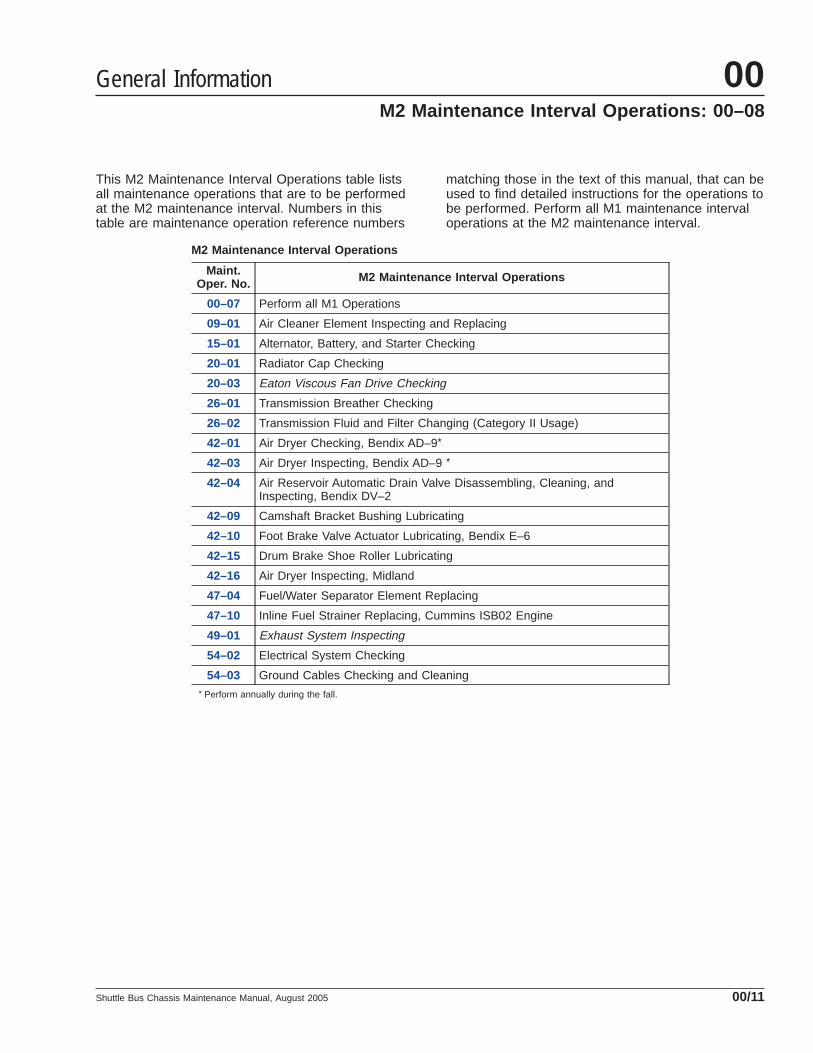
This M2 Maintenance Interval Operations table listsall maintenance operations that are to be performedat the M2 maintenance interval. Numbers in thistable are maintenance operation reference numbers
matching those in the text of this manual, that can beused to find detailed instructions for the operations tobe performed. Perform all M1 maintenance intervaloperations at the M2 maintenance interval.
M2 Maintenance Interval Operations
Maint.Oper. No. M2 Maintenance Interval Operations
00–07 Perform all M1 Operations
09–01 Air Cleaner Element Inspecting and Replacing
15–01 Alternator, Battery, and Starter Checking
20–01 Radiator Cap Checking
20–03 Eaton Viscous Fan Drive Checking
26–01 Transmission Breather Checking
26–02 Transmission Fluid and Filter Changing (Category II Usage)
42–01 Air Dryer Checking, Bendix AD–9*
42–03 Air Dryer Inspecting, Bendix AD–9 *
42–04 Air Reservoir Automatic Drain Valve Disassembling, Cleaning, andInspecting, Bendix DV–2
42–09 Camshaft Bracket Bushing Lubricating
42–10 Foot Brake Valve Actuator Lubricating, Bendix E–6
42–15 Drum Brake Shoe Roller Lubricating
42–16 Air Dryer Inspecting, Midland
47–04 Fuel/Water Separator Element Replacing
47–10 Inline Fuel Strainer Replacing, Cummins ISB02 Engine
49–01 Exhaust System Inspecting
54–02 Electrical System Checking
54–03 Ground Cables Checking and Cleaning* Perform annually during the fall.
General Information 00M2 Maintenance Interval Operations: 00–08
Shuttle Bus Chassis Maintenance Manual, August 2005 00/11
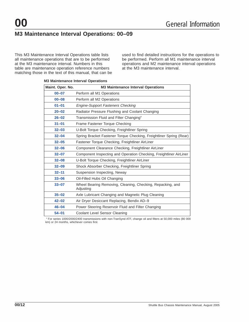
This M3 Maintenance Interval Operations table listsall maintenance operations that are to be performedat the M3 maintenance interval. Numbers in thistable are maintenance operation reference numbersmatching those in the text of this manual, that can be
used to find detailed instructions for the operations tobe performed. Perform all M1 maintenance intervaloperations and M2 maintenance interval operationsat the M3 maintenance interval.
M3 Maintenance Interval Operations
Maint. Oper. No. M3 Maintenance Interval Operations
00–07 Perform all M1 Operations
00–08 Perform all M2 Operations
01–01 Engine-Support Fasteners Checking
20–02 Radiator Pressure Flushing and Coolant Changing
26–02 Transmission Fluid and Filter Changing*
31–01 Frame Fastener Torque Checking
32–03 U-Bolt Torque Checking, Freightliner Spring
32–04 Spring Bracket Fastener Torque Checking, Freightliner Spring (Rear)
32–05 Fastener Torque Checking, Freightliner AirLiner
32–06 Component Clearance Checking, Freightliner AirLiner
32–07 Component Inspecting and Operation Checking, Freightliner AirLiner
32–08 U-Bolt Torque Checking, Freightliner AirLiner
32–09 Shock Absorber Checking, Freightliner Spring
32–11 Suspension Inspecting, Neway
33–06 Oil-Filled Hubs Oil Changing
33–07 Wheel Bearing Removing, Cleaning, Checking, Repacking, andAdjusting
35–02 Axle Lubricant Changing and Magnetic Plug Cleaning
42–02 Air Dryer Desiccant Replacing, Bendix AD–9
46–04 Power Steering Reservoir Fluid and Filter Changing
54–01 Coolant Level Sensor Cleaning* For series 1000/2000/2400 transmissions with non-TranSynd ATF, change oil and filters at 50,000 miles (80 000
km) or 24 months, whichever comes first.
General Information00M3 Maintenance Interval Operations: 00–09
Shuttle Bus Chassis Maintenance Manual, August 200500/12

General Information
Federal Law, Part 205: TransportationEquipment Noise Emission ControlsPart 205, Transportation Equipment Noise EmissionControls, requires the vehicle manufacturer to fur-nish, with each new vehicle, such written instructionsfor the proper maintenance, use, and repair of thevehicle by the ultimate purchaser to provide reason-able assurance of the elimination or minimization ofnoise emission degradation throughout the life of thevehicle. In compliance with the law, the noise emis-sion controls maintenance information located ineach applicable group of this manual, in conjunctionwith the vehicle workshop manual, provides theseinstructions to owners.
Normal Vehicle UseThe maintenance instructions contained in thismanual are based on average vehicle use and nor-mal operating conditions. Unusual vehicle operatingconditions may require service at more frequent in-tervals.
Recommendations for ReplacementPartsReplacement parts used for maintenance or repair ofnoise emission controls should be genuine Allianceparts. If other than genuine Alliance parts are usedfor replacement or repair of components affectingnoise emission control, the owner should be surethat such parts are warranted by their manufacturerto be equivalent to genuine Alliance parts in perfor-mance and durability.
Freightliner Noise Emissions WarrantySee the vehicle owner’s warranty information bookfor warranty information concerning noise emissioncontrols.
Tampering With the Noise Controls isProhibitedFederal law prohibits the following acts or the caus-ing thereof: (1) the removal or rendering inoperativeby any person other than for purposes of mainte-nance, repair, or replacement, of any device or ele-ment of design incorporated into any new vehicle for
the purpose of noise control prior to its sale or deliv-ery to the ultimate purchaser or while it is in use, or(2) the use of the vehicle after such device or ele-ment of design has been removed or rendered inop-erative by any person. Among those acts presumedto constitute tampering are the acts listed below:
A. Removal of engine noise-deadening panels.
B. Removal of, or rendering inoperative, the enginespeed governor so as to allow engine speed toexceed manufacturer’s specifications.
C. Removal of, or rendering inoperative, the fanclutch, including by-passing the control on anythermostatic fan drive to cause it to operate con-tinuously.
D. Removal of the fan shroud.
E. Removal of, or rendering inoperative, exhaustsystem components, including exhaust pipeclamping.
F. Removal of air intake components.
G. Removal of hood liners (noise-deadening pan-els).
Maintenance InstructionsScheduled intervals are in the maintenance table inthis Group. A "Verification of Inspections Log" follows,and should be filled in each time the noise emissioncontrols on the vehicle are maintained or repaired.
General Information 00Noise Emission Controls Maintenance: 00–10
Shuttle Bus Chassis Maintenance Manual, August 2005 00/13
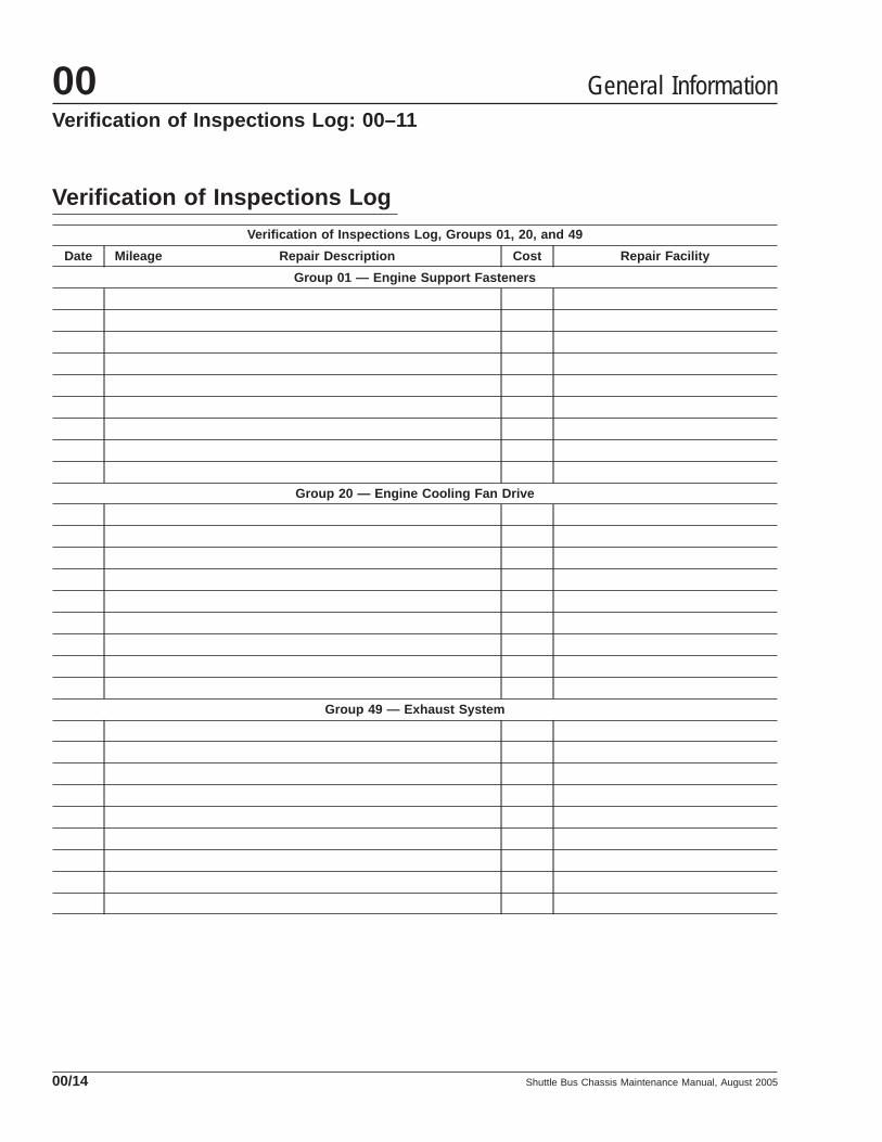
Verification of Inspections LogVerification of Inspections Log, Groups 01, 20, and 49
Date Mileage Repair Description Cost Repair Facility
Group 01 — Engine Support Fasteners
Group 20 — Engine Cooling Fan Drive
Group 49 — Exhaust System
General Information00Verification of Inspections Log: 00–11
Shuttle Bus Chassis Maintenance Manual, August 200500/14

When You Know U.S.Customary
MultiplyBy To Get Metric When You
Know MetricMultiply
By To Get U.S. Customary
Length
inches (in) 25.4 millimeters (mm) 0.03937 inches (in)
inches (in) 2.54 centimeters (cm) 0.3937 inches (in)
feet (ft) 0.3048 meters (m) 3.281 feet (ft)
yards (yd) 0.9144 meters (m) 1.094 yards (yd)
miles (mi) 1.609 kilometers (km) 0.6215 miles (mi)
Area
square inches (in2) 645.16 square millimeters (mm2) 0.00155 square inches (in2)
square inches (in2) 6.452 square centimeters (cm2) 0.155 square inches (in2)
square feet (ft2) 0.0929 square meters (m2) 10.764 square feet (ft2)
Volume
cubic inches (in3) 16387.0 cubic millimeter (mm3) 0.000061 cubic inches (in3)
cubic inches (in3) 16.387 cubic centimeters (cm3) 0.06102 cubic inches (in3)
cubic inches (in3) 0.01639 liters (L) 61.024 cubic inches (in3)
fluid ounces (fl oz) 29.54 milliliters (mL) 0.03381 fluid ounces (fl oz)
pints (pt) 0.47318 liters (L) 2.1134 pints (pt)
quarts (qt) 0.94635 liters (L) 1.0567 quarts (qt)
gallons (gal) 3.7854 liters (L) 0.2642 gallons (gal)
cubic feet (ft3) 28.317 liters (L) 0.03531 cubic feet (ft3)
cubic feet (ft3) 0.02832 cubic meters (m3) 35.315 cubic feet (ft3)
Weight/Force
ounces (av) (oz) 28.35 grams (g) 0.03527 ounces (av) (oz)
pounds (av) (lb) 0.454 kilograms (kg) 2.205 pounds (av) (lb)
U.S. tons (t) 907.18 kilograms (kg) 0.001102 U.S. tons (t)
U.S. tons (t) 0.90718 metric tons (t) 1.1023 U.S. tons (t)
Torque/Work Force
inch–pounds (lbf·in) 11.298 Newton–centimeters (N·cm) 0.08851 inch–pounds (lbf·in)
foot–pounds (lbf·ft) 1.3558 Newton–meters (N·m) 0.7376 foot–pounds (lbf·ft)
Pressure/Vacuum
inches of mercury (inHg) 3.37685 kilo Pascals (kPa) 0.29613 inches of mercury (inHg)
pounds per square inch (psi) 6.895 kilo Pascals (kPa) 0.14503 pounds per square inch (psi)
Table 2, Metric/U.S. Customary Conversion Table
General Information 00Metric/U.S. Customary Conversion Table: 00–12
Shuttle Bus Chassis Maintenance Manual, August 2005 00/15

IMPORTANT: Grade 8 regular hex zinc-yellow platedcapscrews and cadmium- and wax-coated prevailingtorque locknuts may be tightened to a lower torquevalue than the grade 8 regular hex fasteners de-
scribed in Table 3 . See Table 4 for torque values forgrade 8 regular hex zinc-yellow plated capscrewsand cadmium- and wax-coated prevailing torquelocknuts.
Torque Values for U.S. Customary Thread Fasteners With Lubricated * or Plated Threads †
ThreadDiameter–
Pitch
Regular Hex Flanged
Grade 5Bolt
Grade 5 orB Nut
Grade 8 or8.2 Bolt
Grade 8 orC Nut
Grade 5Bolt
Grade BNut
Grade 8 or8.2 Bolt
Grade GNut
Torque: lbf·ft (N·m) Torque: lbf·ft (N·m) Torque: lbf·ft (N·m) Torque: lbf·ft (N·m)
1/4–20
f230002 f230003 f230004 f230005f230006 f230007 f230008 f230009
7 (9) 8 (11) 6 (8) 10 (14)
1/4–28 8 (11) 9 (12) 7 (9) 12 (16)
5/16–18 15 (20) 16 (22) 13 (18) 21 (28)
5/16–24 16 (22) 17 (23) 14 (19) 23 (31)
3/8–16 26 (35) 28 (38) 23 (31) 37 (50)
3/8–24 30 (41) 32 (43) 25 (34) 42 (57)
7/16–14 42 (57) 45 (61) 35 (47) 60 (81)
7/16–20 47 (64) 50 (68) 40 (54) 66 (89)
1/2–13 64 (87) 68 (92) 55 (75) 91 (123)
1/2–20 72 (98) 77 (104) 65 (88) 102 (138)
9/16–12 92 (125) 98 (133) 80 (108) 130 (176)
9/16–18 103 (140) 110 (149) 90 (122) 146 (198)
5/8–11 128 (173) 136 (184) 110 (149) 180 (244)
5/8–18 145 (197) 154 (209) 130 (176) 204 (277)
3/4–10 226 (306) 241 (327) 200 (271) 320 (434)
3/4–16 253 (343) 269 (365) 220 (298) 357 (484)
7/8–9 365 (495) 388 (526) 320 (434) 515 (698)
7/8–14 402 (545) 427 (579) 350 (475) 568 (770)
1–8 — 582 (789) — —
1–12 — 637 (863) — —
1–14 — 652 (884) — —* Freightliner recommends that all plated and unplated fasteners be coated with oil before installation.† Use these torque values if either the bolt or nut is lubricated or plated (zinc-phosphate conversion-coated, cadmium-plated, or waxed).
Table 3, Torque Values for U.S. Customary Thread Fasteners With Lubricated or Plated Threads
General Information00Torque Specifications Tables: 00–13
Shuttle Bus Chassis Maintenance Manual, August 200500/16

Torque Values for Grade 8 Regular Hex Zinc-Yellow Plated Capscrews andCadmium- and Wax-Coated Prevailing Torque Locknuts *
Thread Diameter-Pitch
Regular Hex
Grade 8 or 8.2 Bolt Grade 8 or C Nut
Torque: lbf·ft (N·m)
f230004 f230005
1/4–20 6 (8)
1/4–28 7 (9)
5/16–18 13 (18)
5/16–24 14 (19)
3/8–16 23 (31)
3/8–24 26 (35)
7/16–14 37 (50)
7/16–20 41 (56)
1/2–13 56 (76)
1/2–20 63 (85)
9/16–12 81 (110)
9/16–18 90 (122)
5/8–11 112 (152)
5/8–18 126 (171)
3/4–10 198 (268)
3/4–16 221 (300)
7/8–9 319 (433)
7/8–14 352 (477)
1–8 479 (649)
1–12 524 (710)
1–14 537 (728)* Freightliner recommends that all plated and unplated fasteners be coated with oil before installation.
Table 4, Torque Values for Grade 8 Regular Hex Zinc-Yellow Plated Capscrewsand Cadmium- and Wax-Coated Prevailing Torque Locknuts
General Information 00Torque Specifications Tables: 00–13
Shuttle Bus Chassis Maintenance Manual, August 2005 00/17

Torque Values for U.S. Customary Thread Fasteners With Dry (Unlubricated) * Plain (Unplated) Threads †
ThreadDiameter–Pitch
Regular Hex Flanged
Grade 5 Bolt Grade 5 or BNut
Grade 8 or 8.2Bolt
Grade 8 or CNut
Grade 8 or 8.2Bolt Grade G Nut
Torque: lbf·ft (N·m) Torque: lbf·ft (N·m) Torque: lbf·ft (N·m)
1/4–20
f230002 f230003 f230004 f230005 f230008 f230009
8 (11) 10 (14) —
1/4–28 9 (12) 12 (16) —
5/16–18 15 (20) 22 (30) 22 (30)
5/16–24 17 (23) 25 (34) —
3/8–16 28 (38) 40 (54) 40 (54)
3/8–24 31 (42) 45 (61) —
7/16–14 45 (61) 65 (88) 65 (88)
7/16–20 50 (68) 70 (95) —
1/2–13 70 (95) 95 (129) 95 (129)
1/2–20 75 (102) 110 (149) —
9/16–12 100 (136) 140 (190) 140 (190)
9/16–18 110 (149) 155 (210) —
5/8–11 135 (183) 190 (258) 190 (258)
5/8–18 155 (210) 215 (292) —
3/4–10 240 (325) 340 (461) 340 (461)
3/4–16 270 (366) 380 (515) —
7/8–9 385 (522) 540 (732) —
7/8–14 425 (576) 600 (813) —
1–8 580 (786) 820 (1112) —
1–12 635 (861) 900 (1220) —
1–14 650 (881) 915 (1241) —* Threads may have residual oil, but will be dry to the touch.† Male and female threads (bolt and nut) must both be unlubricated and unplated; if either is plated or lubricated, use Table 3 . Freightliner recommends that all
plated and unplated fasteners be coated with oil before installation.
Table 5, Torque Values for U.S. Customary Thread Fasteners With Dry (Unlubricated) Plain (Unplated) Threads
General Information00Torque Specifications Tables: 00–13
Shuttle Bus Chassis Maintenance Manual, August 200500/18

Torque Values for Metric Thread Fasteners With Lubricated * or Plated Threads †
ThreadDiameter–Pitch
Class 8.8 Bolt Class 8 Nut Class 10.9 Bolt Class 10 Nut
Torque: lbf·ft (N·m) Torque: lbf·ft (N·m)
M6
f230010
8.8
f230011
8
f230012
10.9
f230013
10
5 (7) 7 (9)
M8 12 (16) 17 (23)
M8 x 1 13 (18) 18 (24)
M10 24 (33) 34 (46)
M10 x 1.25 27 (37) 38 (52)
M12 42 (57) 60 (81)
M12 x 1.5 43 (58) 62 (84)
M14 66 (89) 95 (129)
M14 x 1.5 72 (98) 103 (140)
M16 103 (140) 148 (201)
M16 x 1.5 110 (149) 157 (213)
M18 147 (199) 203 (275)
M18 x 1.5 165 (224) 229 (310)
M20 208 (282) 288 (390)
M20 x 1.5 213 (313) 320 (434)
M22 283 (384) 392 (531)
M22 x 1.5 315 (427) 431 (584)
M24 360 (488) 498 (675)
M24 x 2 392 (531) 542 (735)
M27 527 (715) 729 (988)
M27 x 2 569 (771) 788 (1068)
M30 715 (969) 990 (1342)
M30 x 2 792 (1074) 1096 (1486)* Freightliner recommends that all plated and unplated fasteners be coated with oil before installation.† Use these torque values if either the bolt or nut is lubricated or plated (zinc-phosphate conversion-coated,
cadmium-plated, or waxed).
Table 6, Torque Values for Metric Thread Fasteners With Lubricated or PlatedThreads
General Information 00Torque Specifications Tables: 00–13
Shuttle Bus Chassis Maintenance Manual, August 2005 00/19

Title of Maintenance Operation (MOP) MOP Number
Engine Drive Belt Inspecting. . . . . . . . . . . . . . . . . . . . . . . . . . . . . . . . . . . . . . . . . . . . . . . . . . . . . . . . . . 01–02
Engine-Support Fasteners Checking (Noise Emission Control). . . . . . . . . . . . . . . . . . . . . . . . . . . . . . . . . 01–01
Pacbrake Inspecting and Maintenance . . . . . . . . . . . . . . . . . . . . . . . . . . . . . . . . . . . . . . . . . . . . . . . . . . 01–03
Engine 01Index, Alphabetical
Shuttle Bus Chassis Maintenance Manual, June 2003

01–01 Engine-SupportFasteners Checking(Noise EmissionControl)
Check the front and rear engine-support fasteners fortightness. See Fig. 1 . See Section 01.02 of theShuttle Bus Chassis Workshop Manual for proce-dures.
NOTE: At engine overhaul, and whenever theengine has been removed, inspect the lowerand upper isolators and replace them if they areworn. See Fig. 1 . See Section 01.02 of theShuttle Bus Chassis Workshop Manual forprocedures.
01–02 Engine Drive BeltInspecting
WARNINGThe engine and the belt must be cool before youcheck the belt. Handling a hot belt can cause per-sonal injury.
Worn or loose drive belts may cause prematurebearing failure or engine overheating. Excessive ten-sion, or too little tension on the belt may result in ex-cessive and premature belt wear. Poly-V belts, orserpentine belts, are retained by a belt tensioner thatrequires no tension adjustment. Replace the enginedrive belt if any conditions described in the visualdescription are found. V-belts are installed as indi-vidual belts, and as matched sets. When replacing amatched set of belts, always replace both belts at thesame time. Matched belts must be from the samemanufacturer. To inspect a belt, gently twist the beltto view the belt sidewalls and bottom. Visually in-spect all drive belts for the following conditions, thenperform the belt tension inspection.
Visual Inspection1. Inspect the belt for glazing. See Fig. 2 , Ref. A.
Glazing is indicated by shiny sidewalls, and iscaused by friction created when a loose belt slipsin the pulleys. It can also be caused by oil orgrease contamination on the pulleys.
2. Check the belt for ply separation. See Fig. 2 ,Ref. B. Oil, grease, or belt dressing can causethe belt to fall apart in layers. Repair any oil orcoolant leaks that are affecting the belts beforereplacing the drive belts. Do not use belt dress-ing on any belt.
3. Check the belt for a jagged or streaked sidewall.See Fig. 2 , Ref. C. Jagged or streaked sidewallsare the result of foreign objects, such as sand orgravel in the pulley, or a rough pulley surface.
4. Check for tensile breaks (breaks in the cordbody). See Fig. 2 , Ref. D. Cuts in a belt are usu-ally caused by foreign objects in the pulley, or byprying or forcing the belt during removal or instal-lation.
5. Check for uneven ribs on serpentine (poly-V)belts. See Fig. 2 , Ref. E. Foreign objects in thepulley will erode the undercord ribs, causing thebelt to lose its gripping power.
6. Check the drive belts for cracks. See Fig. 2 , Ref.F. Small irregular cracks are usually the signs ofan old belt.
7. Visually inspect the pulleys for excessive play orwobble. Excessive play or wobble indicates afailure of the pulley bearing. Check for belt
f220047a
1
2 3 4 5
6
2
10/05/94
1. Lower Isolator2. Engine Support
Washer3. Capscrew
4. Hexnut5. Engine Mount6. Upper Isolator
Fig. 1, Rear Engine Mount
Engine 01
Shuttle Bus Chassis Maintenance Manual, June 2003 01/1

squealing or squeaking. Replace the bearings asnecessary.
NOTE: If it is difficult to distinguish the locationof a supposed bearing noise, obtain a stetho-scope and place it on the component beingchecked, not the pulley, to isolate the area fromoutside interference.
8. Inspect all pulleys for foreign objects, oil, orgrease in the grooves.
Belt Tension Inspection
Spring-Tension TypeOn belts equipped with a spring tensioner, the belttension is automatically adjusted. Check that the ten-sioner is holding tension on the belt by inserting theend of a breaker bar in the 1/2-inch square hole onthe forward face of the tensioner, and rotating thetensioner down, away from the belt. When thebreaker bar is slowly released, the tensioner should
return to its original position. If not, see Group 01 ofthe Shuttle Bus Chassis Workshop Manual for re-placement instructions.
01–03 Pacbrake Inspecting andMaintenance
With frequent use, the Pacbrake Exhaust Brake willoperate free of maintenance. However, if the vehicleis used inconsistently, seasonally, or is exposed toexcess moisture, it will be necessary to perform pre-ventative maintenance using the following steps:
1. With the engine turned off, use Pacbrake Syn-thetic Lube or Synco Super Lube and spray orcoat a sufficient amount on the restricter air cylin-der valve shaft and the attaching locations ateach end of the actuation cylinder. See Fig. 3 forthe exhaust brake lubrication points.
2. Using your hands or a pair of pliers, slide thevalve several times to distribute the lubricantdown the shaft and the attaching locations.
f150010a
A
B
C
D
E
F11/21/94
A. GlazingB. Separating LayersC. Streaked Sidewalls
D. Tensile BreakE. Uneven RibsF. Cracks
Fig. 2, Drive Belt Replacement Conditions
Engine01
Shuttle Bus Chassis Maintenance Manual, June 200301/2

NOTE: Operation of the Pacbrake could be af-fected by starting the engine and idling for shortperiods of time. During a cold engine start-up,moisture occurs in the engine and the exhaustsystem that creates a corrosion hazard. Thebrake housing may trap water in the valve shaftbore causing corrosion, resulting in an improperor non-functioning brake. If it is necessary toperiodically start the engine, reach normal oper-ating temperatures before shutting down the en-gine.
1
2
f01203503/20/2003
1. Air Cylinder2. Pacbrake
Fig. 3, Pacbrake Exhaust Brake Lube Point Locations
Engine 01
Shuttle Bus Chassis Maintenance Manual, June 2003 01/3

Title of Maintenance Operation (MOP) MOP Number
Air Cleaner Element Inspecting and Replacing . . . . . . . . . . . . . . . . . . . . . . . . . . . . . . . . . . . . . . . . . . . . 09–01
Air Intake System Inspecting. . . . . . . . . . . . . . . . . . . . . . . . . . . . . . . . . . . . . . . . . . . . . . . . . . . . . . . . . . 09–02
Air Intake 09Index, Alphabetical
Shuttle Bus Chassis Maintenance Manual, January 2004

09–01 Air Cleaner ElementInspecting andReplacing
Inspect the the air cleaner element for holes or tearsat the recommended interval. If the air cleaner ele-ment is damaged, replace it. See Group 09 of theShuttle Bus Chassis Workshop Manual for removaland installation instructions.
Replace the air cleaner element at the recommendedinterval or when filter restriction reaches 20 to 25inH20 (if equipped with an air restriction gauge). SeeGroup 09 of the Shuttle Bus Chassis WorkshopManual for air cleaner element removal and installa-tion instructions.
09–02 Air Intake SystemInspecting
Check the air intake system for damaged or crackedhoses and for loose clamps. Make repairs as neces-sary.
Air Intake 09
Shuttle Bus Chassis Maintenance Manual, January 2004 09/1

Title of Maintenance Operation (MOP) MOP Number
Air Compressor Inspecting . . . . . . . . . . . . . . . . . . . . . . . . . . . . . . . . . . . . . . . . . . . . . . . . . . . . . . . . . . . 13–01
Air Compressor 13Index, Alphabetical
Shuttle Bus Chassis Maintenance Manual, July 2000

13–01 Air CompressorInspecting
Inspect the air intake line, oil supply and return lines,and coolant supply and return hoses for tight connec-tions and general condition. Tighten the connections,and replace the lines and hoses, as needed. If thecompressor air-intake adapter is loose, remove theadapter, replace its gaskets, and securely install it.
Check the cooling fins on the compressor crankcase.Clean the fins if they are clogged with debris.
Air Compressor 13
Shuttle Bus Chassis Maintenance Manual, July 2000 13/1

Title of Maintenance Operation (MOP) MOP Number
Alternator, Battery, and Starter Checking. . . . . . . . . . . . . . . . . . . . . . . . . . . . . . . . . . . . . . . . . . . . . . . . . 15–01
Alternators and Starters 15Index, Alphabetical
Shuttle Bus Chassis Maintenance Manual, April 2003

15–01 Alternator, Battery, andStarter Checking
1. Check the tightness of the alternator bracket fas-teners and alternator mounting fasteners; tightenthe fasteners as needed. For torque values, seeGroup 15 of the Shuttle Bus Chassis WorkshopManual.
2. Check that all electrical connections at the alter-nator and starter are clean. Clean and tighten allcharging system electrical connections asneeded.
3. Check the alternator wiring for missing insulation,kinks, and heat damage. Replace or repair asneeded.
WARNINGBatteries release a gas mixture that is explosive.Do not smoke when working around batteries. Putout all flames and remove any source of sparks orintense heat. Make sure the battery compartmenthas been completely vented before disconnectingor connecting the battery cables.
Battery acid is extremely harmful if splashed inthe eyes or on the skin. Always wear a face shieldand protective clothing when working around bat-teries.
4. Inspect the battery cables for wear, and replaceas needed. Clean the cable connector terminalswith a wire brush. See Group 54 of the ShuttleBus Chassis Workshop Manual for troubleshoot-ing instructions, and for adjustment, repair, orreplacement instructions.
4.1 Clean and tighten the battery groundcable, terminal, and clamps.
4.2 Inspect the retainer assembly (or batteryhold-downs) and the battery box. Replaceworn or damaged parts. Remove any cor-rosion with a wire brush, and wash with aweak solution of baking soda and water.Rinse with clean water, and dry. Paint theretainer assembly, if needed, to preventrusting.
4.3 Check that foreign objects, such asstones, bolts, and nuts are removed fromthe battery box.
4.4 After cleaning, connect the cables to thebatteries, and tighten them to the torquespecifications listed on the battery, gener-ally 10 to 15 lbf·ft (14 to 20 N·m).
4.5 Spray each connection with dielectric redenamel and coat the battery terminalswith dielectric grease; see Table 1 .
Approved Dielectric Protectants
Protectant Material Approved Brand
Dielectric Grease Lubriplate FLP DS-ES
Dielectric Red EnamelSpray
3M 1602 IVI-Spray Sealer
Spray-On B-6-665
Table 1, Approved Dielectric Protectants
5. Check the terminals on the battery shut-offswitch and the magnetic switch. Make sure thatthe terminal connections are clean and tight.Coat the terminal connections with dielectric redenamel after cleaning; see Table 1 .
Alternator and Starter 15
Shuttle Bus Chassis Maintenance Manual, April 2003 15/1

Title of Maintenance Operation (MOP) MOP Number
Eaton Viscous Fan Drive Checking (Noise Emission Control). . . . . . . . . . . . . . . . . . . . . . . . . . . . . . . . . . 20–03
Radiator Cap Checking. . . . . . . . . . . . . . . . . . . . . . . . . . . . . . . . . . . . . . . . . . . . . . . . . . . . . . . . . . . . . . 20–01
Radiator Pressure Flushing and Coolant Changing . . . . . . . . . . . . . . . . . . . . . . . . . . . . . . . . . . . . . . . . . 20–02
Engine Cooling/Radiator 20Index, Alphabetical
Shuttle Bus Chassis Maintenance Manual, April 2003

20–01 Radiator Cap Checking
WARNINGDrain the coolant only when the coolant and en-gine are cool. Draining it when these are hot couldcause severe personal injury due to scalding.
The radiator cap is the most often ignored part in thecooling system. If it is suspect, replace it. An inspec-tion means checking the cap with a pressure tester.A radiator cap in good condition will not open below9 psi (62 kPa). A visual check is also in order: lookfor signs of deterioration of the inner gasket. Alsolook for cracks or breaks in the spring retainer in thecap and for corrosion or deposits on the spring itself.If the spring is not in perfect condition, it has prob-ably lost tension; replace it.
20–02 Radiator PressureFlushing and CoolantChanging
NOTE: For additional instructions on cleaningand flushing the cooling system, see the enginemanufacturer’s maintenance and operationmanual.
WARNINGDrain the coolant only when the coolant and en-gine are cool. Draining it when these are hot couldcause severe personal injury due to scalding.
1. Drain the radiator.
1.1 Remove the surge tank cap.
1.2 Remove the plug from the bottom of theradiator on the left side of the tank todrain the engine coolant. See Fig. 1 .
2. Disconnect the radiator inlet and outlet hose con-nections.
3. Flush the radiator.
3.1 Attach a flushing gun nozzle to the radia-tor outlet.
3.2 Run water in until the radiator is full.
3.3 Apply no more than 20 psi (138 kPa) airpressure intermittently to help dislodgesediment buildup in the core.
CAUTIONWhen flushing the radiator, do not apply morethan 20 psi (138 kPa) air pressure. Excessive pres-sure can damage the radiator or heater core.
4. Drain the radiator. Then, flush the radiator untilclean water flows from the it. Remove the flush-ing gun.
5. Install the plug in the bottom of the radiator.
6. Connect the hoses. When you install BreezeConstant-Torque hose clamps, the clamps mustbe tightened to the correct torque. The screw tipof the clamp must extend about 1/4 inch (6 mm)from the clamp housing, and the bellevillewasher stacks must be collapsed almost flat.See Fig. 2 . You must use a torque wrench toinstall these hose clamps correctly. The correctinstallation torque for Breeze Constant-Torquehose clamps is as follows:
For hose clamps with a 5/16-inch tighteningscrew hex: 40 lbf·in (460 N·cm).
For hose clamps with a 3/8-inch tightening screwhex: 90 lbf·in (1020 N·cm).
03/31/2000 f500340
1
2
3
1. Bumper2. Radiator Drain Plug3. Engine
Fig. 1, Radiator Drain Plug
Engine Cooling/Radiator 20
Shuttle Bus Chassis Maintenance Manual, April 2003 20/1

NOTE: All hose clamps will lose torque afterinstallation due to "compression set." However,when correctly installed, Breeze Constant-Torque clamps will hold enough torque to auto-matically adjust and keep consistent sealingpressure. During vehicle operation and shut-down, the screw tip may adjust according totemperature and pressure changes. The torquemay need to be adjusted for individual applica-tions.
7. Fill the radiator with coolant.
Use a mixture of 50 percent water and 50 per-cent corrosion-inhibiting antifreeze to protect theengine to –34°F (–37°C) year round.
See Table 1 for engine cooling system capacityand Table 2 for approved antifreezes.
Coolant Capacities
Engine Make and ModelRadiator Core andSystem Capacity *:
quarts (liters)
Caterpillar CFE Series 28 (26.5)
Cummins B Series and ISB 30.5 (28.9)
Cummins C Series 31.2 (29.5)
Mercedes-Benz 904 Series 29 (27.5)
Mercedes-Benz 906 Series 37.2 (35.2)* System capacity includes all hoses, fittings, and the heater core.
Table 1, Coolant Capacities
Approved Coolants
Coolant Manufacturer CoolantDesignation *
Texaco JC04 Antifreeze
Van Waters and Rogers Ltd.(Canada)
Diesel Antifreeze No.6038
* Freightliner-approved antifreeze must meet one of the following condi-tions: A. Ethylene glycol solution that meets GM 6038–M Engineering Stan-dards. B. Ethylene glycol solution that has less than 0.1% anhydrous so-dium metasilicate, and meets either GM 1825–M or GM 1899–MEngineering Standards.
Table 2, Approved Coolants
20–03 Eaton Viscous Fan DriveChecking (NoiseEmission Control)
CAUTIONIf the fan drive assembly is damaged, replace theunit as soon as possible. Operating a seized orotherwise damaged clutch reduces fuel economy,and could cause serious engine damage.
See Section 20.02 of the Shuttle Bus Chassis Work-shop Manual for replacement instructions.
1. With the engine shut down, rotate the fan atleast one full turn by hand. It should have asmooth, steady drag. If it does not, replace thefan clutch.
2. Check for physical damage to the fan or fanshroud.
3. At the fan clutch mounting:
3.1 Check for correct drive belt alignment andtension. For specifications, see Group 01of the Shuttle Bus Chassis WorkshopManual.
3.2 Check for wear of the fan clutch bearings.There should be no side-to-side or in-and-out movement of the fan clutch.
08/15/94 f200286
A B1
A. The screw tip must extend about 1/4 inch (6 mm).B. The belleville washer stacks must be collapsed
almost flat.1. Tightening Screw Hex
Fig. 2, Breeze Constant-Torque Hose Clamp
Engine Cooling/Radiator20
Shuttle Bus Chassis Maintenance Manual, April 200320/2

3.3 Do all of the checks in Section 20.00 ofthe Shuttle Bus Chassis WorkshopManual.
Engine Cooling/Radiator 20
Shuttle Bus Chassis Maintenance Manual, April 2003 20/3

Title of Maintenance Operation (MOP) MOP Number
Transmission Breather Checking. . . . . . . . . . . . . . . . . . . . . . . . . . . . . . . . . . . . . . . . . . . . . . . . . . . . . . . 26–01
Transmission Fluid Level Checking. . . . . . . . . . . . . . . . . . . . . . . . . . . . . . . . . . . . . . . . . . . . . . . . . . . . . 26–03
Transmission Fluid and Filter Changing. . . . . . . . . . . . . . . . . . . . . . . . . . . . . . . . . . . . . . . . . . . . . . . . . . 26–02
Transmission 26Index, Alphabetical
Shuttle Bus Chassis Maintenance Manual, April 2003

26–01 Transmission BreatherChecking
The breather is located at the top left-rear of thetransmission main housing. The breather prevents airpressure buildup within the transmission.
Transmission housing breathers must remain unob-structed. A plugged breather could result in pressurebuild-up, which could cause oil leakage.
If the breather is plugged, clean or replace it. Checkmore often if the vehicle is operating under verydusty conditions.
CAUTIONWhen cleaning the transmission, do not spraysteam, water, or cleaning solution directly at thebreather. Spraying steam, water, or cleaning solu-tion directly at the breather can force the water orcleaning solution into the transmission and con-taminate the transmission fluid.
26–02 Transmission Fluid andFilter Changing
IMPORTANT: Extended oil and filter change in-tervals (as announced by Allison beginning in2002) do not apply to Allison transmissions inFreightliner-chassis vehicles. Allison transmis-sions are received partially filled with TranSyndsynthetic automatic transmission fluid (ATF).They are then topped-off with a non-TranSyndATF. For this reason, Allison’s extended oil andfilter change intervals for TranSynd-only or for a"mixture" of TranSynd and non-TranSynd do notapply. To qualify for the "mixture" intervals, thetransmission must be drained as in a standardfluid change and then filled with TranSynd. Seethe Allison Owner’s Manual or Allison Operator’sManual for more information.
AT Series1. Park the vehicle on a level surface and apply the
parking brakes.
2. Run the engine until the transmission fluidreaches an operating temperature of 160° to
200°F (71° to 93°C). Shift the transmission toNeutral (N) and shut down the engine.
CAUTIONTo prevent dirt from entering the transmission,use only clean containers and fillers for the trans-mission fluid. Do not use fillers or containers thathave been used for water or antifreeze. Dirt, water,or antifreeze could damage the transmission.
3. Clean the area around the drain plug. While thetransmission fluid is warm, remove the drain plugand drain the fluid. Disconnect the fill tube fromthe oil pan.
IMPORTANT: Examine the used transmissionfluid for dirt, coolant or water, and metal par-ticles. If any of these contaminants are present,a problem may exist within the transmissionsystem.
4. Support the oil pan, then remove all of thewasher-head screws that attach the oil pan tothe transmission case. Remove the pan, and dis-card the pan gasket.
5. Clean the oil pan with mineral spirits.
6. Remove the washer-head screw that attachesthe internal fluid filter to the filter spacer, thenremove the filter and discard it. See Fig. 1 . Re-move the fluid intake tube. Then, remove theseal ring from the intake tube and discard it.
7. Remove, clean, and install the governor feed linescreen, located in the control valve body. SeeFig. 2 .
8. Install a new seal ring on the fluid intake tube.
IMPORTANT: Avoid twisting the intake tubewhen installing the internal fluid filter, intaketube, and seal ring; the seal ring could bepinched, cut, or deformed. An air-tight seal mustbe maintained.
9. Install the intake tube, with the seal ring installed,in the main housing. Install the internal fluid filteron the intake tube, making sure that the grom-met in the filter fits the intake tube snugly.
10. Install the washer-head screw to retain the fluidfilter, and tighten it 10 to 15 lbf·ft (14 to 20 N·m).
Transmission 26
Shuttle Bus Chassis Maintenance Manual, April 2003 26/1

11. Submerge a new oil pan gasket in transmissionfluid for five minutes. Then place the gasket onthe pan; do not use any substance as a gasketretainer.
IMPORTANT: Do not use gasket-sealing com-pounds any place inside of the transmission orwhere they might be washed into the transmis-sion. Also, nonsoluble vegetable-based cookingcompounds or fibrous greases must not be usedinside of the transmission.
12. Install the oil pan and gasket.
12.1 Guide the pan and gasket carefully intoplace. Guard against dirt or foreign mate-rial entering the pan. Retain the pan withfour 5/16–18 washer-head screws, in-stalled by hand in the corners of the pan.
12.2 Install the remaining washer-head screwsby hand, carefully threading each throughthe gasket and into the transmission. Bot-tom all of the screws before tighteningany of them.
12.3 Tighten all of the screws evenly 10 to 15lbf·ft (14 to 20 N·m). Check the gasket fitwhile the screws are being tightened.
IMPORTANT: The oil pan bolts must main-tain a minimum torque of 60 lbf·in (680N·cm) after the oil pan gasket has taken aset.
13. Install the fill tube at the side of the pan. Tightenthe tube fitting 90 to 100 lbf·ft (122 to 136 N·m).
14. Install the drain plug and gasket, and tighten theplug 15 to 20 lbf·ft (20 to 27 N·m).
15. Replace the external (auxiliary) fluid filter.
16. Clean the area around the fill tube and removethe dipstick. Using a clean funnel in the fill tube,add transmission fluid. See Table 1 for approvedtransmission lubricants, and Table 2 for lubricantcapacities.
Approved Transmission Lubricants *
Lubricant Type Temperature
Dexron III ATF –25° to +120°F (–32° to +48°C)
TranSyndSynthetic ATF –25° to +120°F (–32° to +48°C)
* Factory filled with Dexron III. For off-highway operation or where ambienttemperature is consistently above +86°F (+30°C) or below –25°F (–32°C),see the manufacturer’s fluid recommendations.
Table 1, Approved Transmission Lubricants
Lubricant Capacities, AT/1000/2000/2400/MD SeriesTransmissions
Model Refill Capacity *:quarts (liters)
AT–542 16.0 (15.1)
AT–545 21.0 (19.9)
1000/2000/2400 Standard Sump 10.6 (10)
1000/2000/2400 Shallow Sump 7.4 (7)
MD–3060P17.5 (16.5)
MD–3060PR* Quantities listed are approximate. Add the recommended amount of fluid
as listed under refill capacity, then perform a "hot check" and add fluid asneeded. Do not overfill.
Table 2, Lubricant Capacities, AT/1000/2000/2400/MDSeries Transmissions
17. Check and adjust the fluid level using the proce-dure under "Transmission Fluid Level Checking."
f260133a
1
2
3
4
5
6
10/05/94
1. Fluid Intake Tube2. Filter Spacer3. Internal Fluid Filter4. Washer-Head Screw
5. Governor PressureTube
6. Governor Feed Tube
Fig. 1, AT Series Transmission Filter
Transmission26
Shuttle Bus Chassis Maintenance Manual, April 200326/2

MD Series1. See Fig. 3 . Park the vehicle on a level surface
and set the parking brake.
2. Run the engine until the transmission fluidreaches an operating temperature of 160 to200°F (71 to 93°C). Shift the transmission toNeutral (N) and shut down the engine.
CAUTIONTo prevent dirt from entering the transmission,use only clean containers and fillers for the trans-mission fluid. Do not use fillers or containers that
have been used for water or antifreeze. Dirt, water,or antifreeze could damage the transmission.
3. Clean the area around the drain plug. While thetransmission fluid is warm, remove the drainplug, and drain the fluid.
IMPORTANT: Examine the used transmissionfluid for dirt, coolant or water, and metal par-ticles. If any of these contaminants are present,a problem within the transmission system mayexist.
4. Remove the bolts from each filter cover at thebottom of the transmission control module. Re-move the filter covers, O-rings, seals, and thetwo cartridge-type filters.
f260132a
12
34
56
7
8 9 10
10/05/94
1. Fluid Intake Tube2. Detent Spring3. Detent Spring 1-3/4" Bolt4. Filter Spacer5. 2-1/4" Bolt (16 qty.)6. First/Reverse Clutch Feed Tube 3" Bolt (2 qty.,
behind)
7. First/Reverse Clutch Feed Tube8. Governor Screen (in control valve body)9. Governor Pressure Tube10. Governor Feed Tube
Fig. 2, AT Series Transmission Governor
Transmission 26
Shuttle Bus Chassis Maintenance Manual, April 2003 26/3

5. Coat the O-rings lightly with clean transmissionfluid. Place the O-rings, seals, and filters on thefilter covers. Push each cover assembly into thebottom of the transmission to seat the seals. In-stall and tighten the bolts 38 to 45 lbf·ft (52 to 61N·m). Install and tighten the drain plug 18 to 24lbf·ft (24 to 33 N·m).
6. Clean the area around the fill tube and removethe dipstick. Using a clean funnel in the fill tube,add transmission fluid. See Table 1 for approvedtransmission lubricants, and see Table 2 for MDseries lubricant capacities.
7. Check and adjust the fluid level using the proce-dures under "Transmission Fluid Level Check-ing."
1000/2000/2400 SeriesWhen draining transmission fluid, check for evidenceof dirt or water contamination. A small amount ofcondensation will appear in the fluid during operation.
Water contamination is normally characterized as amilky discoloration of the transmission fluid. Obviouscontamination of the transmission fluid indicates aleak between the water and fluid areas of the trans-mission cooler. Inspect and pressure-test the coolerto confirm the leak; replace leaking transmissioncoolers.
CAUTIONTo prevent dirt from entering the transmission,use only clean containers and fillers for the trans-mission fluid. Do not use fillers or containers thathave been used for water or antifreeze. Dirt, water,or antifreeze could damage the transmission.
1. Park the vehicle on a level surface and set theparking brake.
2. Operate the vehicle until the transmissionreaches normal operating temperature: 160 to200°F (71 to 93°C).
3. Clean the area around the drain plug and thetransmission fluid pan. Place a drain pan underthe transmission and remove the drain plug. Ex-amine the fluid as it drains.
4. Place a drain pan under the external filter. SeeFig. 4 . Remove the external filter with a straptype filter wrench by turning it counterclockwise.
5. Remove the magnet from the filter attachmenttube or the top of the filter element. Clean anydebris from the magnet.
NOTE: Report to your maintenance personalany debris attached to the magnet larger thandust.
6. Reinstall the magnet onto the filter attachmenttube.
7. Lubricate the gasket on the filter with cleantransmission fluid.
f260130a
1
2
3
4
5
6
706/04/99
1. Drain Plug O-Ring2. Drain Plug3. Filter4. Filter O-Ring
5. Seal6. Filter Cover7. M10 Bolt
Fig. 3, MD Series Transmission
Transmission26
Shuttle Bus Chassis Maintenance Manual, April 200326/4

8. Install, by hand, the filter until the gasket on thefilter touches the converter housing or coolermanifold.
9. Turn the filter ONE FULL TURN ONLY after thegasket contact.
10. Replace the drain plug O-ring, and install thedrain plug. Tighten the drain plug 22 to 30 lbf·ft(30 to 40 N·m).
11. Refill the transmission with fresh transmissionfluid. See Table 1 for approved lubricants.
12. Check the fluid level. See Table 2 for lubricantcapacities.
Check and adjust the fluid level using the proce-dures under "Transmission Fluid Level Check-ing."
26–03 Transmission FluidLevel Checking
CAUTIONOperating a transmission with the fluid levelhigher or lower than recommended can result intransmission damage. Do not overfill the transmis-sion.
Do not mix types and brands of fluid, because ofpossible incompatibility. Do not use fluid addi-tives, friction modifiers, extreme-pressure gearfluids, or multi-viscosity lubricants.
Cold CheckClean all dirt away from around the end of the fluidfill tube before removing the dipstick.
CAUTIONDo not allow foreign matter to enter the transmis-sion. Dirt or foreign matter in the hydraulic systemmay cause undue wear of transmission parts,make valves stick, and clog passages.
NOTE: It is important to check the fluid levelcold to determine if the transmission has a suffi-cient amount of fluid to be safely operated untila hot check can be performed.
1. A cold check may be made when the sump tem-perature is 60 to 104°F (15 to 40°C).
2. Run the engine for at least one minute to clearthe fluid system of air.
3. With the engine running, wipe the dipstick cleanand check the fluid level. Any level within theCOLD RUN (lower) band is satisfactory for oper-ating the vehicle. See Fig. 5 . If the level is notwithin the COLD RUN band, add or drain fluiduntil it reaches the middle of the COLD RUNband.
4. Perform a hot check at the first opportunity afternormal operating temperature, 160 to 200°F (71to 93°C), is reached.
03/31/2000 f261061
1
2
1. Magnet2. External Filter
Fig. 4, 1000/2000/2400 Series Transmission ExternalFilter
Transmission 26
Shuttle Bus Chassis Maintenance Manual, April 2003 26/5

Hot Check1. Operate the transmission in a Drive (D) range
until normal operating temperature, 160 to 200°F(71 to 93°C), is reached.
NOTE: The fluid must be warm to ensure anaccurate check. The fluid level rises as tempera-ture increases.
2. Park the vehicle. Shift to Neutral (N) and set theparking brake. Let the engine run at idle.
3. Wipe the dipstick clean and check the fluid level.A safe operating level is any level within the HOTRUN (upper) band on the dipstick. See Fig. 5 .
4. If the fluid is not within this range, add or drainfluid as needed to bring the level to the top ofthe HOT RUN band.
COLDRUN CHECK IN NEUTRAL @ IDLE USE DEXRON R OILHOT
RUNREFFILL
08/23/96 f011103
Fig. 5, Dipstick Markings
Transmission26
Shuttle Bus Chassis Maintenance Manual, April 200326/6
Title of Maintenance Operation (MOP) MOP Number
Frame Fastener Torque Checking. . . . . . . . . . . . . . . . . . . . . . . . . . . . . . . . . . . . . . . . . . . . . . . . . . . . . . 31–01
Frame 31Index, Alphabetical
Shuttle Bus Chassis Maintenance Manual, April 2003

31–01 Frame Fastener TorqueChecking
Because of "bedding in" (or seating), the frame fas-teners must be torqued at the recommended inter-vals. These intervals apply to new vehicles, and toframe fasteners that have been removed and in-stalled again.
CAUTIONMake sure frame fasteners are properly tightened.Continued vehicle operation with loose fastenerscould result in bracket or frame damage.
Typical frame fastener applications include suspen-sion and fuel tank brackets, exhaust and engine sup-ports, and frame crossmembers and gussets.
NOTE: This operation is not intended to be abolt-by-bolt check of the entire chassis. Do ahand check of the typical frame fasteners. If anyfasteners are found loose, tighten them to thecorrect torque value.
See Group 00 of the Shuttle Bus Chassis WorkshopManual for additional information on fasteners andtorque values.
Frame 31
Shuttle Bus Chassis Maintenance Manual, April 2003 31/1

Title of Maintenance Operation (MOP) MOP Number
Component Clearance Checking, Freightliner AirLiner . . . . . . . . . . . . . . . . . . . . . . . . . . . . . . . . . . . . . . . 32–06
Component Inspecting and Operation Checking, Freightliner AirLiner . . . . . . . . . . . . . . . . . . . . . . . . . . . . 32–07
Fastener Torque Checking, Freightliner AirLiner. . . . . . . . . . . . . . . . . . . . . . . . . . . . . . . . . . . . . . . . . . . . 32–05
Shock Absorber Checking, Freightliner Spring. . . . . . . . . . . . . . . . . . . . . . . . . . . . . . . . . . . . . . . . . . . . . 32–09
Spring Bracket Fastener Torque Checking, Freightliner Spring (Rear). . . . . . . . . . . . . . . . . . . . . . . . . . . . 32–04
Suspension Inspecting, Freightliner Spring . . . . . . . . . . . . . . . . . . . . . . . . . . . . . . . . . . . . . . . . . . . . . . . 32–01
Suspension Inspecting, Neway . . . . . . . . . . . . . . . . . . . . . . . . . . . . . . . . . . . . . . . . . . . . . . . . . . . . . . . . 32–11
Suspension Lubricating, Freightliner Spring. . . . . . . . . . . . . . . . . . . . . . . . . . . . . . . . . . . . . . . . . . . . . . . 32–02
Torque Arm Bushing Checking, Freightliner AirLiner. . . . . . . . . . . . . . . . . . . . . . . . . . . . . . . . . . . . . . . . . 32–10
U-Bolt Torque Checking, Freightliner AirLiner. . . . . . . . . . . . . . . . . . . . . . . . . . . . . . . . . . . . . . . . . . . . . . 32–08
U-Bolt Torque Checking, Freightliner Spring . . . . . . . . . . . . . . . . . . . . . . . . . . . . . . . . . . . . . . . . . . . . . . 32–03
Suspension 32Index, Alphabetical
Shuttle Bus Chassis Maintenance Manual, March 2005

32–01 Suspension Inspecting,Freightliner Spring
Front and Rear Suspension SpringAssembliesInspect the front and rear suspension spring assem-blies for pitted, cracked, broken, or abnormally bentleaves and extreme rust. If any of these conditionsexist, replace the spring assembly. See Group 32 ofthe Shuttle Bus Chassis Workshop Manual for in-structions.
WARNINGDo not replace individual leaves of a damaged leafspring assembly; replace the complete spring as-sembly. Visible damage (cracks or breaks) to oneleaf causes hidden damage to other leaves. Re-placement of only the visibly damaged part(s) isno assurance that the spring is safe. On frontspring assemblies if cracks or breaks exist in thetwo top leaves, a loss of vehicle control could oc-cur. Failure to replace a damaged spring assemblycould cause an accident resulting in propertydamage, serious personal injury or death.
IMPORTANT: On multi-leaf suspensions, closelyinspect each component of the leaf spring as-semblies, including the brackets, U-bolts, andrelated parts.
Rear Suspension Spring BracketsInspect the forward and rear spring brackets and thewear pads, for wear, cracks, and other damage. Ifany of these conditions exist, replace the damagedbracket(s) and wear pad(s). See Group 32 of theShuttle Bus Chassis Workshop Manual for instruc-tions.
WARNINGReplace worn, cracked, or damaged spring brack-ets. Failure to do so could result in bracket break-age, possibly leading to loss of vehicle controland resulting in personal injury or property dam-age.
32–02 Suspension Lubricating,Freightliner Spring
Front SuspensionWipe all dirt from the grease fittings at the forwardspring pin and the spring shackle pins; then applymultipurpose chassis grease with a pressure gun un-til the old grease is forced out.
Rear SuspensionLubricate the spring pin by applying multipurposechassis grease at the grease fitting. See Fig. 1 . Lu-bricate with a grease gun until grease appears at thebase of the fitting.
32–03 U-Bolt Torque Checking,Freightliner Spring
Check the U-bolt torque of both the front and rearaxles.
CAUTIONFailure to retorque the U-bolt nuts could result inspring breakage and abnormal tire wear.
f320268a10/05/94
Fig. 1, Forward Spring Bracket Spring Pin GreaseFitting
Suspension 32
Shuttle Bus Chassis Maintenance Manual, March 2005 32/1

In a diagonal pattern, tighten all 5/8–18 U-bolt nuts205 lbf·ft (278 N·m); tighten all 3/4–16 U-bolt nuts300 lbf·ft (407 N·m); and tighten all 7/8–14 U-boltnuts 460 lbf·f (624 N·m).
32–04 Spring Bracket FastenerTorque Checking,Freightliner Spring(Rear)
CAUTIONContinued use with loose fasteners could result inbracket and frame damage.
Torque the fasteners that attach the forward and rearspring brackets and equalizer brackets to the framerail. Tighten 1/2–13 locknuts with hardened washers85 lbf·ft (115 N·m). Tighten 5/8–11 locknuts withhardened washers 170 lbf·ft (230 N·m). Tighten3/4–10 locknuts with hardened washers 305 lbf·ft(415 N·m).
See Group 00 for other frame fastener torque val-ues.
32–05 Fastener TorqueChecking, FreightlinerAirLiner
Tighten all suspension fasteners to the torque valuesin Table 1 . Also, tighten all suspension air line fittingsand air lines.
Torque Values for Freightliner AirLiner Suspensions
Description Size Torque:lbf·ft (N·m)
Leveling Valve Adjustment Nut 1/4–20 5 (7)
Leveling Valve Mounting BoltNuts 5/16–18 14 (19)
Air Spring Upper MountingLocknuts
3/4–16 45 (61)
1/2–13 23 (31)
Air Spring Lower MountingLocknuts 1/2–13 55 (75)
Leaf Spring Mounting Eye BoltLocknuts 3/4–16 270 (365)
Torque Values for Freightliner AirLiner Suspensions
Description Size Torque:lbf·ft (N·m)
Shock Absorber Upper BracketMounting Locknuts 5/8–11 125 (170)
Air Spring Upper MountingBracket 5/8–11 125 (170)
Spring Hanger MountingLocknuts 3/4–10 210 (285)
Torque Arm Rod Nut 5/8–11 136 (185)
Table 1, Torque Values for Freightliner AirLinerSuspensions
32–06 Component ClearanceChecking, FreightlinerAirLiner
Check that the air line support brackets are posi-tioned so that air lines do not rub against anything.Reposition any configurations that could contact andresult in friction and wear. There must be at least 1inch (25 mm) clearance around the rubber air springwhen inflated. If the clearance is less than 1 inch (25mm), relocate the obstructing parts.
CAUTIONFailure to relocate obstructing parts could resultin damage to the air spring.
32–07 Component Inspectingand Operation Checking,Freightliner AirLiner
WARNINGInspect the components and check their operationas described below. Failure to perform these in-spections and checks could result in separation ofworn suspension components and loss of vehiclecontrol, possibly causing personal injury andproperty damage.
1. Chock the front tires. Raise the rear of the ve-hicle so that the tires just clear the ground andso that the suspension is fully extended. Placesafety stands under the vehicle frame.
Suspension32
Shuttle Bus Chassis Maintenance Manual, March 200532/2

2. Squeeze all air springs to check for completedeflation. If any air springs remain partially orfully inflated, see Group 32 of the Shuttle BusChassis Workshop Manual.
3. Inspect each air spring for wear at its connectionto the pedestal. Replace any worn air springs; forinstructions, see Group 32 of the Shuttle BusChassis Workshop Manual.
4. Check the axle connection welds (beam-seat toequalizing-beam) and axle-adapter to axle forcracks. If welds are cracked, grind them out andreweld the parts.
5. Move the axle up and down while checking forsigns of looseness due to worn parts at the frontpivot connections. Replace any worn parts byfollowing the procedures in Group 32 of theShuttle Bus Chassis Workshop Manual.
6. Inspect the shock absorbers for oil leaks andworn rubber bushings. Replace the shock ab-sorbers and/or rubber bushings if wear or dam-age is noted. For instructions, see Group 32 ofthe Shuttle Bus Chassis Workshop Manual.
7. Remove the safety stands and lower the rear ofthe vehicle to the ground. Run the engine untilair pressure of at least 100 psi (689 kPa) ismaintained throughout the system.
8. Check that all air springs are inflated. If the airsprings do not inflate, see Group 32 of theShuttle Bus Chassis Workshop Manual for pos-sible causes and corrections.
32–08 U-Bolt Torque Checking,Freightliner AirLiner
In a diagonal pattern, tighten all 5/8–18 U-bolt nuts205 lbf·ft (278 N·m); tighten all 3/4–16 U-bolt nuts300 lbf·ft (407 N·m); and tighten all 7/8–14 U-boltnuts 460 lbf·ft (624 N·m).
CAUTIONFailure to retorque the U-bolt nuts could result inspring breakage and abnormal tire wear.
32–09 Shock AbsorberChecking, FreightlinerSpring
Make sure that the shock absorber brackets aretight, and that the shock absorber is not striking orrubbing on the frame or some other part of the chas-sis. See Fig. 2 . Check the rubber mounting bushingsand replace if worn. Inspect the shock absorber foroil leakage.
If the shock absorber is worn or damaged, replace itwith a new one.
32–10 Torque Arm BushingChecking, FreightlinerAirLiner
1. Without detaching the torque arms, attempt tomove (by hand) each of the rod ends up, down,
f320267a10/05/94
1
2
3
1. Upper Mounting Bracket2. Shock Absorber3. Lower Mounting Bracket
Fig. 2, Shock Absorber Installation (front suspensionshown)
Suspension 32
Shuttle Bus Chassis Maintenance Manual, March 2005 32/3

in, and out. See Fig. 3 . If there is any move-ment, replace the torque arm.
2. Inspect the rubber bushing ends. Replace thetorque arm if there are gaps between the rubberbushing and the pin or the outer steel sleeve. Ifeither bushing end contacts a torque arm pinmounting bolt, if there are cracks in the bushing,or if part of the rubber bushing extends beyondthe outside circumference of the outer bushingsleeve, replace the torque arm.
IMPORTANT: Be sure to follow the maintenanceschedule for checking the torque of the controlrod fasteners; see Table 1 for control rod torquevalues.
32–11 Suspension Inspecting,Neway
WARNINGInspect the components and check their operationas described below. Failure to perform these in-spections and checks could result in separation ofworn suspension components and loss of vehiclecontrol, possibly causing personal injury or death,or property damage.
1. Chock the front or the rear tires. Working at thefront of the vehicle or at the rear of the vehicle,raise the vehicle so that the tires just clear theground and the suspension is fully extended.Place safety stands under the vehicle frame. SeeFig. 4 .
2. Squeeze all air springs to check for completedeflation. If any air springs remain partially orfully inflated, see Group 32 of the Shuttle BusChassis Workshop Manual. Inspect the airsprings for cracks, tears, or other damage.
3. Inspect each air spring for wear at the pedestalconnection. Inspect for leaks at the upper andlower pedestal connections using a soapy solu-tion. Replace any worn air springs; for instruc-tions, see Group 32 of the Shuttle Bus ChassisWorkshop Manual.
4. Inspect the bolts and nuts at the pivot connec-tions, the transverse beam connections, and theaxle connections to ensure they are tightened tothe correct torque specification.
5. Check all of the other suspension componentsfor any sign of damage, looseness, wear, orcracks. Replace worn or damaged parts. SeeGroup 32 of the Shuttle Bus Chassis WorkshopManual.
6. Inspect for cracked welds. If cracks are found,contact Neway immediately for further instruc-tions.
7. Inspect the torque rod and track bar pivot bush-ings for excessive wear. Replace worn or dam-aged bushings. See Group 32 of the Shuttle BusChassis Workshop Manual.
8. Move the axle up and down while checking forsigns of looseness due to worn parts at the frontpivot connections. Replace any worn parts byfollowing the procedures in Group 32 of theShuttle Bus Chassis Workshop Manual.
9. Check for leaks on the height control valves byapplying a soapy solution, then watching forbubbles at all air connections and fittings.
10. Inspect the shock absorbers for oil leaks andworn rubber bushings. Replace the shock ab-sorbers and/or rubber bushings if wear or dam-age is noted. For instructions, see Group 32 ofthe Shuttle Bus Chassis Workshop Manual.
04/01/2000 f350396
1
2 3
1. Torque Arm2. Exhaust Pipe3. Rear Axle Housing
Fig. 3, Torque Arm
Suspension32
Shuttle Bus Chassis Maintenance Manual, March 200532/4

11. Remove the safety stands and lower the vehicleto the ground. Run the engine until air pressureof at least 100 psi (689 kPa) is maintainedthroughout the system.
IMPORTANT: Repeat this check at both ends ofthe vehicle.
12. Check that all air springs are inflated. If the airsprings do not inflate, see Group 32 of theShuttle Bus Chassis Workshop Manual for pos-sible causes and corrections.
02/21/2005 f321032
Fig. 4, Holland ® Neway® ADL 120/123 Suspension
Suspension 32
Shuttle Bus Chassis Maintenance Manual, March 2005 32/5

Title of Maintenance Operation (MOP) MOP Number
Knuckle Pin Lubricating . . . . . . . . . . . . . . . . . . . . . . . . . . . . . . . . . . . . . . . . . . . . . . . . . . . . . . . . . . . . . 33–01
Oil-Filled Hubs Oil Changing. . . . . . . . . . . . . . . . . . . . . . . . . . . . . . . . . . . . . . . . . . . . . . . . . . . . . . . . . . 33–06
Oil-Filled Hubs Oil Level Checking . . . . . . . . . . . . . . . . . . . . . . . . . . . . . . . . . . . . . . . . . . . . . . . . . . . . . 33–05
Tie-Rod End Inspecting . . . . . . . . . . . . . . . . . . . . . . . . . . . . . . . . . . . . . . . . . . . . . . . . . . . . . . . . . . . . . 33–03
Tie-Rod End Lubricating. . . . . . . . . . . . . . . . . . . . . . . . . . . . . . . . . . . . . . . . . . . . . . . . . . . . . . . . . . . . . 33–02
Wheel Alignment Checking, Front Axle . . . . . . . . . . . . . . . . . . . . . . . . . . . . . . . . . . . . . . . . . . . . . . . . . . 33–04
Wheel Bearing Removing, Cleaning, Checking, Repacking, and Adjusting . . . . . . . . . . . . . . . . . . . . . . . . 33–07
Front Axle 33Index, Alphabetical
Shuttle Bus Chassis Maintenance Manual, July 2003

33–01 Knuckle Pin LubricatingHold a pressure gun on each fitting until fresh greaseappears. See Fig. 1 or Fig. 2 . This will ensure thatall of the old contaminated grease has been forcedout. It is not necessary to exceed 4000 psi (27 560kPa). The best distribution of new lubricant and thebest purging of old lubricant occurs when about 4000psi (27 560 kPa) pressure is applied at the greasegun nozzle. Using a 40 to 1 booster, the air shouldbe limited to 100 psi (689 kPa); using a 50 to 1booster, the air should be limited to 80 psi (551 kPa).Higher or lower pressures are not recommended.
When lubricating Meritor knuckle pin bushings or Alli-ance Brand Product (ABP) axle needle bearings forInitial Maintenance, raise the front axle until the fronttires are off of the ground. Wipe the lube fittingsclean, and slowly feed (for Meritor axles) multipur-pose chassis grease (NLGI grade 1 or 2) into eachbushing area, or (for ABP axles), lithium 12-hydroxystearate (with molybdenum disulfide) WL grade 2grease into each needle bearing area, while turningthe wheels from extreme right to left and back again(lock-to-lock). This will eliminate small air pocketsand improve grease distribution.
Lower the front axle so that the tires are on theground, and regrease both top and bottom bushings
or needle bearings until new grease is seen at theseal on the bushing or needle bearing opposite thefittings.
NOTE: The grease seal will accept the greasepressure without damaging the seal, and is de-signed to have grease pumped out through itduring lubrication. Even if grease leaks outaround the top or bottom plate, continue pump-ing until new grease is seen at the seal on thebushing or needle bearing opposite the greasefitting.
When lubricating knuckle pin bushings or needlebearings at M1 through M3, do not raise the frontaxle. Wipe the lube fittings clean, and (for Meritoraxles) apply multipurpose chassis, or (for ABP axles),lithium 12-hydroxy stearate (with molybdenum disul-fide) WL grade 2 grease, until new grease is seen atthe grease seal on the bushing or needle bearingopposite the fittings.
33–02 Tie-Rod End LubricatingWipe the tie-rod end grease fittings clean, then (forMeritor axles) pump multipurpose chassis grease(NLGI grade 1 or 2), or (for ABP axles), lithium 12-hydroxy stearate (with molybdenum disulfide) WLgrade 2 grease, to the tie-rod ends until all usedgrease is forced out and new grease appears at theball stud neck.
f320032a
1
1
A
10/20/93
Pump lubricant into each grease fitting until fresh greasecomes out at A.
1. Grease Fitting
Fig. 1, Meritor Axle Grease Fittings
06/13/2003 f3302131
1
2
1. Grease Fitting2. Steering Knuckle
Fig. 2, ABP Axle Grease Fittings
Front Axle 33
Shuttle Bus Chassis Maintenance Manual, July 2003 33/1

33–03 Tie-Rod End InspectingIMPORTANT: DOT roadside tie-rod assemblyreplacement criteria specifies that if tie-rod end-play is 1/8 inch (3 mm) or greater, measured onthe road, the vehicle must be taken out of ser-vice immediately. If less than 1/8 inch (3 mm),the vehicle does not have to be taken out ofservice but a major out-of-service inspectionand maintenance must be scheduled as soonas possible.
1. Check the tie-rod ends for looseness.
1.1 Park the vehicle so that the front wheelsare in the "straight ahead" position.
1.2 Chock the front and rear tires.
1.3 Remove dirt and grease from the seals orboots on the tie-rod ends. Visually inspectthe tie-rod ends. Replace the tie-rod endsif the seals or boots are cracked, worn, ordamaged.
CAUTIONCheck the tie-rod endplay by hand. Do not use apry bar. If a pry bar is used, the dial indicator willnot read correctly.
NOTE: for accurate readings, use a dial indi-cator with a "contour-type" base.
1.4 Position the dial indicator so that the baseof the indicator is on the bottom of thetie-rod arm. Place the tip of the indicatoron the bottom of the tie-rod end at thecenter of the ball stud on the surface thatis most flat, as shown in Fig. 3 .
1.5 Set the dial indicator to zero.
1.6 By hand, move the tie-rod end and thecross tube assembly up and down. If thedial indicator reads more than 0.060 inch(1.52 mm), replace the tie-rod end atonce.
1.7 Install the dial indicator as describedabove, and repeat this procedure on theopposite tie-rod end.
2. Inspect the tie-rod ends.
2.1 The threaded portion of the tie-rod endassembly must be inserted all the wayinto the cross-tube split, for adequateclamping. See Fig. 4 . Replace the parts ifthis cannot be done. For instructions, seethe axle manufacturer’s service manual.
2.2 Check the tie-rod end nut and clamp nuttorques. For Meritor axles, tighten the tie-rod end nut 100 lbf·ft (136 N·m), andtighten the clamp nut 40 to 55 lbf·ft (54 to75 N·m). For ABP axles, see Table 1 fortie-rod end nut torque specifications andTable 2 for tie-rod end clamp nut torquespecifications.
ABP Axle Tie-Rod End Nut
Thread Torque: lbf·ft (N·m)
5/8–16 60 to 115 (81 to 156)
5/8–18 60 to 115 (81 to 156)
3/4–16 90 to 170 (122 to 230)
7/–14 160 to 300 (217 to 407)
Table 1, ABP Axle Tie-Rod End Nut
ABP Axle Tie-Rod End Clamp Nut
Thread Torque: lbf·ft (N·m)
1/2–13 35 to 45 (47 to 61)
5/8–11 40 to 60 (54 to 81)
5/8–18 50 to 64 (73 to 87)
3/4–10 155 to 175 (210 to 237)
Table 2, ABP Axle Tie-Rod End Clamp Nut
33–04 Wheel AlignmentChecking, Front Axle
See Group 33 of the Shuttle Bus Chassis WorkshopManual for wheel alignment checking and adjustingprocedures.
Front Axle33
Shuttle Bus Chassis Maintenance Manual, July 200333/2

33–05 Oil-Filled Hubs Oil LevelChecking
WARNINGBe careful not to overfill the hubs. Overfilling maycause oil to be forced out of the hubs and to con-taminate the brake linings and other brake compo-nents. This could result in loss of vehicle controland lead to personal injury and property damage.
1. With the vehicle on a level surface, rotate thefront wheels and allow the oil in the hubs tosettle.
2. Chock the tires.
IMPORTANT: The oil level should be at, or nomore than 1/4 inch (6 mm) above, the level indi-cators on the hub caps.
3. If necessary, remove the filler caps (in the endsof the hub caps) and add enough oil (80/90 hy-poid gear oil) to bring the oil to the proper level.
4. Rotate the wheels, allow the oil to settle, andcheck the levels again.
5. Install the filler caps securely.
6. Remove the chocks from the tires.
33–06 Oil-Filled Hubs OilChanging
WARNINGBe careful not to overfill the hubs. Overfilling maycause oil to be forced out of the hubs and to con-taminate the brake linings and other brake compo-nents. This could result in loss of vehicle controland lead to personal injury and property damage.
1. With the vehicle on a level surface, rotate thefront wheels so that the front hub drain plugs arepositioned downward.
2. Chock the tires.
3. Place suitable containers under the hubs, re-move the filler caps (in the ends of the hub caps)and the drain plugs, and allow the hubs to draincompletely.
07/18/96 f330131
1
2
NOTE: If the reading is more than 0.060 inch (1.52 mm)when moving the tie-rod end and cross tube assemblyup and down, replace the tie-rod end.
1. Tie-Rod End2. Dial Indicator with "Contour-Type" Base
Fig. 3, Measuring Tie-Rod End Looseness
f320033a
1
10/20/93
OK
OK
IMPORTANT: The tie-rod end threads must be visiblethroughout the entire length of the split.
NOTE: Pinch bolt not shown to provide clarity.
1. Cross-Tube Split
Fig. 4, Tie-Rod End Adjustment
Front Axle 33
Shuttle Bus Chassis Maintenance Manual, July 2003 33/3

4. Install the drain plugs and tighten securely.
5. Add approximately 1 to 1-1/2 pints (0.5 to 0.7 L)of oil (80/90 hypoid gear oil) to each hub.
6. Rotate the wheels, allow the oil to settle, andcheck the levels.
IMPORTANT: Fill the hubs to the level indicatorson the hub caps, or to no more than 1/4 inch (6mm) above the indicators.
7. Install the filler caps securely.
8. Remove the chocks from the tires.
33–07 Wheel BearingRemoving, Cleaning,Checking, Repacking,and Adjusting
See Group 33 of the Shuttle Bus Chassis WorkshopManual for wheel bearing service procedures.
Front Axle33
Shuttle Bus Chassis Maintenance Manual, July 200333/4

Title of Maintenance Operation (MOP) MOP Number
Axle Breather Checking . . . . . . . . . . . . . . . . . . . . . . . . . . . . . . . . . . . . . . . . . . . . . . . . . . . . . . . . . . . . . 35–03
Axle Lubricant Changing and Magnetic Plug Cleaning . . . . . . . . . . . . . . . . . . . . . . . . . . . . . . . . . . . . . . . 35–02
Axle Lubricant Level Checking . . . . . . . . . . . . . . . . . . . . . . . . . . . . . . . . . . . . . . . . . . . . . . . . . . . . . . . . 35–01
Rear Axle 35Index, Alphabetical
Shuttle Bus Chassis Maintenance Manual, July 2003

35–01 Axle Lubricant LevelChecking
CAUTIONFailure to keep the rear axle filled to the properlevel with the recommended lubricant can result inrear axle damage.
NOTE: If the vehicle is exposed to water deepenough to cover the hubs, disassemble and in-spect them for water damage and/or contamina-tion. See Group 35 of the Shuttle Bus ChassisWorkshop Manual for instructions.
1. Clean the oil fill hole plug, located in the carrieror the side of the axle housing, and the area sur-rounding it. Remove the plug.
NOTE: Some Meritor axles have a small tappedand plugged hole located near and below thehousing oil fill hole. This smaller hole is for thelubricant temperature sensor only, and must notbe used as a fill or level hole.
2. With the vehicle on level ground, lubricant mustbe level with the bottom of the oil fill hole.
If low, add lubricant. See Table 1 for AllianceBrand Product (ABP) axle lubricant capacities.See Table 2 for Meritor axle lubricant capacitiesand see Table 3 for approved Meritor axle lubri-cants.
3. On ABP axles, install the fill hole plug, andtighten it securely.
4. On Meritor axles, install the fill hole plug, andtighten 35 lbf·ft (47 N·m).
ABP Drive Axle Lubricant Capacities
Differential/Hubs Capacity: quarts (liters)
Differential Only 5.8 (5.5)
Differential and Hubs 7.4 (7.0)
Table 1, ABP Drive Axle Lubricant Capacities
Meritor Drive Axle Lubricant Capacities (single axle) *
Axle Model Capacity: pints (liters) †
RS–13–120 16 (7.6)
RS–15–120 16 (7.6)
RS–17–145 33.6 (15.9)
RS–19–145 34.4 (16.3)
RS–21–145 32 (15.1)
RS–23–160 42 (19.9)
RS–26–180 46.6 (22)* Single drive axles equipped with traction equalizers may require a "friction
modifier" to correct a slip-stick condition, as described in the vehicle driver’smanual. Meritor’s experience shows that the following additives perform ad-equately: Add Elco No. 2 Friction Modifier (1 ounce [30 ml] of additive foreach 1 pint [0.5 liter] of lube capacity) or Lubrizol No. 797 or 762 (oneounce [30 mL] of additive for each 1 pint [0.5 liter] of lube capacity).† Quantities listed are approximate and include 1 pint (0.5 liter) for each
wheel end and with the drive pinion at 3 degrees.
Table 2, Meritor Drive Axle Lubricant Capacities
RecommendedLubricant Type Ambient Temperature Lubricant SAE
Viscosity GradeMeritor
Specification
Hypoid Gear OilAPI Service
Classification GL–5
+10°F (–12.2°C) and up* 85W–140 0–76–A
–15°F (–26.1°C) and up* 80W–140 0–76–B
–15°F (–26.1°C) and up* 80W–90 0–76–D
–40°F (–40°C) and up* 75W–90 0–76–E
–40°F (–40°C) to +35°F (+2°C) 75W 0–76–J
–40°F (–40°C) and up* 75W–140 0–76–L
Synthetic Gear Oil–40°F (–40°C) and up* 75W–90 0–76–N
–40°F (–40°C) and up* 75W–140 0–76–M* There is no upper limit on these ambient temperatures, but axle sump temperature must never exceed 250°F (121°C).
Table 3, Meritor Drive Axle Approved Lubricants
Rear Axle 35
Shuttle Bus Chassis Maintenance Manual, July 2003 35/1
35–02 Axle Lubricant Changingand Magnetic PlugCleaning
A regular schedule for changing the axle lubricant ina particular vehicle and operation can be accuratelydetermined by analyzing oil samples taken from theaxle at specified intervals or mileages. Lubricant sup-pliers frequently make their laboratory facilities avail-able for determining the useful life of their productunder actual service conditions. The final schedulethat is recommended may, for economic reasons, becorrelated with lubricant changes that are governedby climatic conditions and magnetic plug mainte-nance. Change lubricant type and viscosity as cli-matic temperatures demand, regardless of vehiclemileage or established change schedule.
The normal operating temperature of compoundedlubricants during the summer season is about 160 to220°F (71 to 104°C). The chemicals and additivesthat give these lubricants increased load-carrying ca-pacity, oxidize faster at temperatures above 220°F(104°C), contributing to more rapid lubricant deterio-ration. For this reason, lubricants of this type, thatoperate continuously at high temperatures, must bechanged more frequently.
CAUTIONFailure to change the axle lubricant at more fre-quent intervals, when adverse operating condi-tions require, could result in axle damage.
Alliance Brand Products (ABP) Axles1. Remove the filler plug, then the drain plug (in the
center bottom of the axle housing), and allow thedifferential to drain completely.
2. Install the drain plug and tighten it securely.
3. Fill the differential with 80/90 hypoid gear oilthrough the rear axle fill hole. See Table 1 foraxle lubricant capacities.
NOTE: A normal oil change does not include thehubs. Drain the differential and add 5.8 qt (5.5L) of SAE 80/90 hypoid gear oil through the rearaxle fill hole. The lubricant level should be at thebottom of the fill hole.
IMPORTANT: The entire axle capacity (axlecompletely dry) is 7.4 qt (7 L). Each hub con-tains 0.80 qt (0.75 L) of lubricant. To protect theouter bearings from oil starvation, jack up (ar-ticulate) each side of the axle a minimum of 4inches (10 cm) to ensure that oil flows to theouter bearings. Articulate the short-side arm for45 seconds and the long-side arm for 90 sec-onds. After articulating the axle, add 0.80 qt(0.75 L) of lubricant through the fill hole (in addi-tion to the 5.8 qt [5.5 L] of a normal oil change)for each hub that has been removed. Check theoil level again and ensure that the axle is nei-ther under nor overfilled.
4. Install the fill plug and tighten it securely.
Meritor Axles
Axle Draining and Flushing1. Remove the plug at the bottom of the housing
and drain the lubricant while the unit is warm.Allow enough time for all of the old lubricant todrain completely.
2. Flush the unit with clean flushing oil, then drain itcompletely.
IMPORTANT: Do not flush axles with solvent,such as kerosene.
3. Clean the drain plugs. For magnetic drain plugs,a piece of key stock or any other convenientsteel slug may be used to short the two magneticpoles and divert the magnetic field.
NOTE: Meritor recommends using magneticplugs with elements having a minimum pickupcapacity of 2 pounds (1 kg) of low-carbon steel,in plate or bar form. Magnets will rapidly loseeffectiveness as collected material bridges thegap between the two poles. Clean or changethe plugs before this occurs. It may be neces-sary to clean or change the plugs one or moretimes between lubrication change intervals.
4. After cleaning the drain plugs, install and tightenthem 35 lbf·ft (47 N·m).
Rear Axle35
Shuttle Bus Chassis Maintenance Manual, July 200335/2

Axle Filling1. With the vehicle on a level surface, fill the axle
housing to the bottom of the oil fill hole (in thecarrier or housing) with lubricant. See Table 2 foraxle lubricant capacities and see Table 3 for ap-proved axle lubricants.
NOTE: Meritor axles have a small tapped andplugged hole located near and below the hous-ing oil fill hole. This smaller hole is for the lubri-cant temperature sensor only, and must not beused as a fill or level hole.
2. Install the fill hole plug, and tighten it 35 lbf·ft (47N·m).
3. After filling the carrier and housing assembly withlubricant, drive the vehicle, unloaded, for 1 or 2miles (2 or 3 kilometers) at speeds not to exceed25 mph (40 km/h), to thoroughly circulate thelubricant throughout the assembly.
35–03 Axle Breather CheckingNOTE: On ABP axles, the axle housing breatheris located on the carrier assembly.
The axle housing breather must remain unob-structed. Whenever the axle lubricant level ischecked, also check that the axle breather is open.Check more often under poor operating conditions. Ifthe breather is plugged, clean or replace it asneeded.
Rear Axle 35
Shuttle Bus Chassis Maintenance Manual, July 2003 35/3

Title of Maintenance Operation (MOP) MOP Number
Wheel Nut and Rim Nut Checking. . . . . . . . . . . . . . . . . . . . . . . . . . . . . . . . . . . . . . . . . . . . . . . . . . . . . . 40–01
Wheels and Tires 40Index, Alphabetical
Shuttle Bus Chassis Maintenance Manual, July 2000

40–01 Wheel Nut and Rim NutChecking
IMPORTANT: In addition to the maintenanceinterval in this manual, check the wheel nuttorque the first 50 to 100 miles (80 to 160 km)of operation after a wheel has been removedand installed.
When checking wheel nuts on a dual disc assembly,remove one outer nut at a time, tighten the inner nut,then reinstall the outer nut. Repeat this procedure forall of the inner wheel nuts in the sequence shown in
Fig. 1 , then tighten all of the outer wheel nuts in thesame sequence.
CAUTIONToo little wheel nut torque can cause wheelshimmy, resulting in wheel damage, stud break-age, and extreme tire tread wear. Too much wheelnut torque can break studs, damage threads, andcrack discs in the stud hole area.
See Table 1 , Table 2 , Table 3 , or Table 4 for wheelnut torque specifications, and see Fig. 1 for the tight-ening sequence.
Fastener Torque for 10-Hole Disc Wheel With Inner and Outer Locknuts
Description Nut Size WheelManufacturer
Torque (dry threads):lbf·ft (N·m)
Front Wheel Nut 3/4–16, 1-1/8–16 Accuride 450–500 (610–680)
Rear Wheel Inner Nut 3/4–16 Accuride 450–500 (610–680)
Rear Wheel Outer Nut 1-1/8–16 Accuride 450–500 (610–680)
Wheel Stud Retainer Nut 3/4–16 Accuride 175–200 (235–270)
Table 1, Fastener Torque for 10-Hole Disc Wheel With Inner and Outer Locknuts
Fastener Torque for 8-Hole Disc Wheel With Cone Locknuts
Description Nut Size Torque (lubricated threads):lbf·ft (N·m)
Front and Rear Wheel Nuts M20 280–310 (380–420)
Table 2, Fastener Torque for 8-Hole Disc Wheel With Cone Locknuts
Fastener Torque for 10-Stud Hub-Piloted Wheels
Description Nut Size Torque (lubricated threads):lbf·ft (N·m)
Front and Rear Wheel Nuts M22 390–500 (529–678)
Table 3, Fastener Torque for 10-Stud Hub-Piloted Wheels
Spoke-Type Wheel Fastener Torque
Description Size WheelManufacturer
Torque (dry threads):lbf·ft (N·m)
Front Wheel Nut, 5- and6-Spoke 3/4–10 Gunite 200–225 (270–305)
Rear Wheel Nut, 5- and6-Spoke With Channel Spacer(Fig. 2 )
3/4–10 Gunite 200–225 (270–305)
Wheels and Tires 40
Shuttle Bus Chassis Maintenance Manual, July 2000 40/1

Spoke-Type Wheel Fastener Torque
Description Size WheelManufacturer
Torque (dry threads):lbf·ft (N·m)
Rear Wheel Nut, 5- and6-Spoke With CorrugatedChannel Spacer (Fig. 3 )
3/4–10 Gunite 240–260 (325–350)
Table 4, Spoke-Type Wheel Fastener Torque
1
2
3
45
6
7
8
9
101
2
3
45
6
1
2
3 4
5
f40005705/27/93
1 2
3
4
5 6
7
8
A B C D
A. 8-Stud Disc WheelB. 10-Stud Disc Wheel
C. 6-Spoke WheelD. 5-Spoke Wheel
Fig. 1, Wheel Nut and Rim Nut Tightening Sequence
f400033a05/16/94
Fig. 2, Non-Corrugated Channel Spacer
f400032a10/05/94
Fig. 3, Corrugated Channel Spacer
Wheels and Tires40
Shuttle Bus Chassis Maintenance Manual, July 200040/2
Title of Maintenance Operation (MOP) MOP Number
Driveline Inspecting and Lubricating . . . . . . . . . . . . . . . . . . . . . . . . . . . . . . . . . . . . . . . . . . . . . . . . . . . . 41–01
Driveline 41Index, Alphabetical
Shuttle Bus Chassis Maintenance Manual, July 2000

41–01 Driveline Inspecting andLubricating
InspectingBefore lubricating the driveline U-joints and slip-joints, make the following checks:
1. Check that the yoke-strap capscrews, see Fig. 1 ,Ref. 4 are tightened as follows:
• Spicer SPL90 and 1610: 50 to 60 lbf·ft (68to 81 N·m)
• Spicer 1710 and 1760: 125 to 135 lbf·ft(170 to 183 N·m)
CAUTIONDo not overtighten the yoke-strap capscrews, dueto the extreme load occurring at high-speed rota-tion. A loose or broken capscrew at any point inthe driveline weakens the driveline connection,which could eventually result in serious vehicledamage.
f410057a10/06/94
1 2
3
56
4
2
4
716
15
14
13
18
17
9
8
3
7
1011
12
NOTE: Not all fasteners are shown.
1. Transmission2. Half-Round End Yoke3. U-Joint Assembly4. Yoke Strap and Capscrew5. Coupling Shaft6. Midship Bearing and Mount7. Bearing Cup
8. Slip-Joint Assembly9. Driveshaft Tube10. Driveshaft Yoke11. Input Shaft Half-Round End
Yoke12. Rear Axle
13. Splined Shaft14. Dust Seal15. Sleeve Yoke16. Full-Round-Yoke Lug17. U-Joint Cross18. Lockplate and Capscrew
Fig. 1, Driveline Assembly With Midship Bearing
Driveline 41
Shuttle Bus Chassis Maintenance Manual, July 2000 41/1

2. Check each of the output and input end yokes,see Fig. 1 , Refs. 2 and 11 for cracks and loose-ness. Replace cracked yokes. If any end yokecan be moved in or out on its shaft, or can berocked on its shaft, disconnect the driveshaft andU-joint from the end yoke. Check the drive com-ponent’s shaft seal for leakage or other visibledamage that may have been caused by theloose yoke. Replace the seal if needed. Tightenthe end-yoke nut to the value in Table 1 . If theend yoke is still loose after tightening the yokenut, install a new yoke and yoke nut.
End-Yoke Nut Torque Specifications
Description ThreadSize Torque: lbf·ft (N·m)
Transmissions
Allison AT Series 1/2–20* 102–121 (138–164)
Allison 2000 and2400 Series 1/2–20 80–100 (108–136)
Single Axle Input Shaft
Coupling Shaft (Midship Bearings)
Spicer SPL90,1610, 1710 1-1/4–18 475–525 (644–712)
* The Allison AT transmission output shaft end-yoke is retained by a 1/2-20x 1-1/2-inch bolt and a 1-1/16-inch washer. Both the bolt and the washermust be replaced each time they are removed.
Table 1, End-Yoke Nut Torque Specifications
NOTE: If the end-yoke locknut was removed forany reason, install a new one.
3. Check the U-joint assemblies for wear by at-tempting to move the driveshaft up and down,and from side to side. If movement of the U-jointtrunnion in the bearings is greater than 0.006inch (0.15 mm), replace the U-joint assembly.
4. Check the midship bearing and bracket for loose-ness and deterioration by attempting to move thedriveshaft up and down, and from side to side. Ifthe bearing is loose on its shaft, or rattles, re-place it. If the bearing bracket is loose on theframe, or the bearing mount is loose on thebracket, tighten the mounting bolt nuts 91 lbf·ft(123 N·m). Replace the midship bearing assem-bly if the rubber cushion is worn or oil-soaked.
5. Check the slip-joints for spline wear by trying tobend the sleeve-yoke and splined shaft back andforth, see Fig. 2 . If looseness is greater than
0.007 inch (0.18 mm), replace both the sleeve-yoke and the splined shaft.
6. Check the driveshaft tubes for dents, bends,twists, or other damage. If any tube appears tobe damaged, remove the driveshaft and checkthe runout on the tube. If the tube is not straight(and cannot be straightened) within 0.005 inch(0.127 mm) on the slip-joint seal surface of thesplined shaft, 0.010 inch (0.254 mm) on the tube3 inches (76 mm) from the front and rear welds,and 0.015 inch (0.381 mm) at the center of thetube, replace the tube. See Fig. 3.
If the driveshaft tube requires straightening orreplacement, balance the repaired driveshaft be-fore installing it. See Group 41 of the ShuttleBus Chassis Workshop Manual.
f410012a05/27/93
Attempt to bend the sleeve yoke and splined shaft backand forth.
Fig. 2, Slip-Joint Spline Wear Checking
f410110b06/13/96
A A
B
C CD
A. Measurement: 3" (76 mm)B. Measurement: 0.005" (0.127 mm)C. Measurement: 0.010" (0.254 mm)D. Measurement: 0.015" (0.381 mm)
Fig. 3, Driveshaft Runout Specifications
Driveline41
Shuttle Bus Chassis Maintenance Manual, July 200041/2

7. Check the driveshaft for missing balanceweights, and for debris build-up. Remove anybuild-up. If any balance weights are missing, re-move the driveshaft and have it balanced; seeGroup 41 of the Shuttle Bus Chassis WorkshopManual.
8. Check the side and bottom clearance betweenthe draveshaft and the 3 driveline guards. SeeFig. 4 . There should be 1-1/2 inches of clear-ance on each side and 3 inches of clearancebetween the driveshaft and the bottom of theguard.
9. For driveshafts with slip-joints, check that theyoke plug is not loose or missing. See Fig. 5 ,Ref. 2. Replace the yoke plug if needed. If theyoke plug is missing, the splined shaft may behitting the yoke plug and knocking it out; checkthe driveshaft for proper length.
U-Joint Lubricating1. Wipe all old grease and dirt from each U-joint
grease fitting. See Fig. 5 , Ref. 8.
2. Use a hand-type grease gun, or a high-pressuregun with a low-pressure adapter, to lubricate theU-joints.
NOTE: If a low-pressure adapter is not usedwith the high-pressure gun, the U-joints may notreceive enough lubricant.
3. Using lithium 12 hydroxy stearate grease (NLGIgrade 1 or 2, with EP additives), lubricate untilnew grease can be seen at all four U-joint seals.
IMPORTANT: Fresh lubricant must be seen es-caping from all four bearing cup seals of eachU-joint.
On full-round yokes, if most of the grease beingadded to a U-joint can be seen escaping fromjust one of the U-joint seals, bend the tabs ofthe lockstrap away from the heads of the bear-
03/31/2000
A
A
B
1
2
3
f410462
A. 1.5 inches (38.1 mm) B. 3 inches (76.2 mm)1. Driveshaft2. Frame Bracket3. Driveshaft Guard
Fig. 4, Driveshaft-to-Driveline Guard Clearance
f410050a 10/20/93
1
1
2 3
3
3 4
5
6
7
8
A
A. After grease appears, cover the pressure-relief holewhile continuing to lubricate.
1. Slip-Joint GreaseFitting (with greasegun attached)
2. Yoke Plug3. Grease4. Half-Round Yoke
5. Yoke Plug Pressure-Relief Hole
6. Slip-Joint Seal7. Full-Round Yoke8. U-Joint Grease Fitting
Fig. 5, Slip-Joint and U-Joint Lubricating
Driveline 41
Shuttle Bus Chassis Maintenance Manual, July 2000 41/3

ing cup capscrews, then check the torque onthe bearing cup capscrews at that seal. Tightenthe bearing cup capscrews as follows:
• 5/16–24 capscrews: 24 lbf·ft (32 N·m)
• 3/8–24 capscrews: 37 lbf·ft (50 N·m)
Bend the lockstrap tabs up, against a flat side ofeach capscrew. If the capscrews were alreadytight, or all of the U-joint seals still do not purge,remove the bearing cup at that seal, and exam-ine the seal for damage. If the seal is damaged,replace the complete U-joint assembly.
If grease does not appear at one of the seals,use a screwdriver to pry the U-joint trunnionaway from the non-purging seal, or tap thedriveshaft or yoke with a plastic or rawhide mal-let (on the side opposite the dry seal), whilecontinuing to apply gun pressure. If grease stilldoes not appear, bend the tabs of the lockstrapaway from the heads of the bearing cup cap-screws, then loosen the bearing cup capscrews(at the bearing with the dry seal) to relieve sealtension. Lubricate the U-joint until the oldgrease is purged, then tighten the capscrews tothe above specifications, and bend the tabs ofthe lockstrap against a flat side of each cap-screw. If the bearing will not take grease, re-place the U-joint assembly; see Group 41 of theShuttle Bus Chassis Workshop Manual.
4. Check the old grease. If it appears rusty, gritty, orburned, replace the U-joint assembly. See Group41 of the Shuttle Bus Chassis Workshop Manual.
5. Wipe any excess grease from the seals andgrease fittings.
Slip-Joint Spline Lubricating1. Wipe all old grease and dirt from the slip-joint
grease fitting. See Fig. 5 , Ref. 1.
2. Use a hand-type grease gun or a high-pressuregun with a low-pressure adapter, to lubricate theslip-joint. Using lithium 12 hydroxy stearategrease (NLGI grade 1 or 2, with EP additives),lubricate until fresh grease appears at thepressure-relief hole in the yoke plug. Then coverthe relief hole with your finger, while continuingto lubricate until fresh grease appears at the slip-
joint seal, see Fig. 5 , Ref. 6. This ensures com-plete lubrication of the splines.
3. Wipe any excess grease from the pressure-reliefhole, slip-joint seal, and grease fitting.
Driveline41
Shuttle Bus Chassis Maintenance Manual, July 200041/4
Title of Maintenance Operation (MOP) MOP Number
ABS Tone Rings Cleaning. . . . . . . . . . . . . . . . . . . . . . . . . . . . . . . . . . . . . . . . . . . . . . . . . . . . . . . . . . . . 42–14
Air Dryer Checking, Bendix AD–9 . . . . . . . . . . . . . . . . . . . . . . . . . . . . . . . . . . . . . . . . . . . . . . . . . . . . . . 42–01
Air Dryer Desiccant Replacing, Bendix AD–9. . . . . . . . . . . . . . . . . . . . . . . . . . . . . . . . . . . . . . . . . . . . . . 42–02
Air Dryer Desiccant and Coalescent Filter Replacing, Midland . . . . . . . . . . . . . . . . . . . . . . . . . . . . . . . . . 42–17
Air Dryer Inspecting, Bendix AD–9 . . . . . . . . . . . . . . . . . . . . . . . . . . . . . . . . . . . . . . . . . . . . . . . . . . . . . 42–03
Air Dryer Inspecting, Midland . . . . . . . . . . . . . . . . . . . . . . . . . . . . . . . . . . . . . . . . . . . . . . . . . . . . . . . . . 42–16
Air Reservoir Automatic Drain Valve Disassembling, Cleaning, and Inspecting,Bendix DV–2. . . . . . . . . . . . . . . . . . . . . . . . . . . . . . . . . . . . . . . . . . . . . . . . . . . . . . . . . . . . . . . . . . . . . 42–04
Automatic Slack Adjuster Lubricating and Checking, Meritor. . . . . . . . . . . . . . . . . . . . . . . . . . . . . . . . . . . 42–05
Bendix Hydro-Max® Power Booster Checking . . . . . . . . . . . . . . . . . . . . . . . . . . . . . . . . . . . . . . . . . . . . . 42–06
Brake Caliper Slide Pin Lubricating, Bosch Brakes . . . . . . . . . . . . . . . . . . . . . . . . . . . . . . . . . . . . . . . . . 42–13
Brake Caliper Slide Rail Lubricating, Bosch Hydraulic Brakes . . . . . . . . . . . . . . . . . . . . . . . . . . . . . . . . . 42–12
Brake Lines Checking, Hydraulic Disc Brakes . . . . . . . . . . . . . . . . . . . . . . . . . . . . . . . . . . . . . . . . . . . . . 42–07
Brake Lining Wear Checking, Hydraulic Disc Brakes . . . . . . . . . . . . . . . . . . . . . . . . . . . . . . . . . . . . . . . . 42–08
Camshaft Bracket Bushing Lubricating . . . . . . . . . . . . . . . . . . . . . . . . . . . . . . . . . . . . . . . . . . . . . . . . . . 42–09
Drum Brake Shoe Roller Lubricating. . . . . . . . . . . . . . . . . . . . . . . . . . . . . . . . . . . . . . . . . . . . . . . . . . . . 42–15
Foot Brake Valve Actuator Lubricating, Bendix E–6 . . . . . . . . . . . . . . . . . . . . . . . . . . . . . . . . . . . . . . . . . 42–10
Relay Valve Checking, Midland. . . . . . . . . . . . . . . . . . . . . . . . . . . . . . . . . . . . . . . . . . . . . . . . . . . . . . . . 42–11
Brakes 42Index, Alphabetical
Shuttle Bus Chassis Maintenance Manual, April 2003

42–01 Air Dryer Checking,Bendix AD–9
During cold-weather operation, check the operationof the end cover heater and thermostat assembly.
1. With the ignition switch in the ON position, checkfor voltage to the heater and thermostat assem-bly. Unplug the electrical connector at the airdryer, and place the test leads of a voltmeter oneach of the pins of the male connector. If there isno voltage, look for a blown fuse, broken wires,or corrosion in the vehicle wiring harness. Checkthat a good ground path exists.
2. Check the thermostat and heater operation. Turnthe ignition switch to the OFF position and coolthe end cover assembly to below 40°F (4°C).Using an ohmmeter, check the resistance be-tween the electrical pins in the female connector.The resistance should be 1.5 to 3.0 ohms for the12-volt heater assembly.
Warm the end cover assembly to over 90°F(32°C) and again check the resistance. It shouldexceed 1000 ohms. If it does, the thermostat andheater assembly is operating properly. If it doesnot, replace the purge-valve housing assembly,which includes the heater and thermostat assem-bly.
42–02 Air Dryer DesiccantReplacing, Bendix AD–9
The desiccant change interval may vary from vehicleto vehicle. Although typical desiccant cartridge life isthree years, many will perform adequately for alonger period of time. To take maximum advantage ofdesiccant life and ensure that replacement occursonly when necessary, disassemble, clean, and in-spect the air dryer. Replace the desiccant cartridge ifnecessary. For instructions, see Group 42 of theShuttle Bus Chassis Workshop Manual.
42–03 Air Dryer Inspecting,Bendix AD–9
1. Check the reservoirs for moisture. A smallamount (a teaspoon or less) is normal. Larger
amounts may mean that the desiccant needs tobe replaced. Check the mounting and connectinglines.
2. Tighten the fasteners attaching the air dryer tothe vehicle. Use the following torque values.
28 lbf·ft (38 N·m) for SAE grade 5, 3/8–16 fas-teners.
135 lbf·ft (183 N·m) for SAE grade 5, 5/8–11 fas-teners.
Check all air lines, fittings, and electrical connec-tions for damage, leakage, or looseness.
3. Replace damaged or leaking parts, and tightenloose fittings or electrical connections.
42–04 Air Reservoir AutomaticDrain ValveDisassembling,Cleaning, andInspecting, Bendix DV–2
Disassemble the drain valve, clean the parts withmineral spirits, and inspect the parts. Replace all rub-ber parts and any worn or damaged parts; use onlygenuine Bendix replacement parts or kits. Assembleand install the valve, then check for proper operationand leakage. For instructions, see Group 42 of theShuttle Bus Chassis Workshop Manual.
42–05 Automatic SlackAdjuster Lubricating andChecking, Meritor
1. Lubricate the slack adjusters using high-temperature, water-proof grease NLGI grade 1,Texaco Thermotex EP 1, Shell Darina No. 1,Marathon 528 heavy-duty, Sunaplex No. 1 EP,Amdex No. 1 EP, or Philube B No. 1. It shouldbe smooth-textured, corrosion-resistant grease,free of fillers and abrasives. See Fig. 1 .
2. Check the boots for cuts, tears, etc., and replacethem if necessary.
3. Check the brake shoe lining wear to determinethe proper reline time.
Brakes 42
Shuttle Bus Chassis Maintenance Manual, April 2003 42/1

4. Check the free-stroke. If the vehicle has newbrakes or brakes with new linings, you mustcheck the free-stroke. If the vehicle is in for rou-tine maintenance and the brakes or linings arenot new, go to the next step and check the brakechamber stroke.
IMPORTANT: Do not use installation tem-plates to check the slack adjuster angles.Installation templates are used only wheninstalling a new slack adjuster or reinstallingthe existing slack adjuster.
4.1 With the brakes fully released, measurethe distance from the bottom of the brakechamber to the center of the large clevispin. See Fig. 2 , Ref. A.
4.2 Use a pry bar to move the slack adjuster,applying the brakes. Again, measure thedistance from the bottom of the brakechamber to the center of the large clevispin. See Fig. 2 , Ref. B.
The difference between the two measure-ments is the initial free-stroke, and setsthe clearance between the linings and the
drum. The free-stroke must be 5/8 to 3/4inch (16 to 19 mm).
4.3 If the free-stroke is incorrect, remove thepressure-relief capscrew, gasket, pawlspring, and pawl from the slack adjusterhousing. See Fig. 1 , Ref. 5. If equippedwith a pull-pawl assembly, carefully inserta screwdriver and raise the relief capabout 1/8 inch (3.2 mm). See Fig. 3 .
CAUTIONBefore turning the adjusting nut, remove the pres-sure relief capscrew, spring, and pawl assembly. Ifequipped with a pull-pawl assembly, raise the re-lief cap as instructed. Failure to do so could stripthe teeth on the pawl.
4.4 Turn the adjusting nut 1/8 turn, as shownin Fig. 4 . Measure the stroke again, andadjust until correct.
CAUTIONDo not make the adjusted chamber stroke tooshort. The free-stroke must not be less than the
f420012a10/20/93
1
2
3
4
5
6
7
1. Brake Chamber2. Clevis3. Actuator Rod4. Boot5. Pressure-Relief Capscrew, Gasket, Pawl Spring,
and Pawl6. Manual Adjusting Nut7. Grease Fitting (or Lube Plug)
Fig. 1, Meritor Automatic Slack Adjuster
A B
09/27/94 f420180a
NOTE: For a drum brake, A minus B must equal 5/8 in.to 3/4 in. (16 to 19 mm).
A. With the brakes applied, measure this distance.B. With the brakes released, measure this distance.
Fig. 2, Measuring Free-Stroke
Brakes42
Shuttle Bus Chassis Maintenance Manual, April 200342/2

measurements given previously. If the chamberstroke is too short, the linings can drag, whichcould damage the brake.
4.5 If removed, install the pawl, pawl spring,gasket, and pressure-relief capscrew.Tighten the capscrew 15 to 20 lbf·ft (20 to27 N·m). Or, remove the screwdriver fromthe pull-pawl assembly (if so equipped).
5. Check for correct brake chamber stroke.
5.1 With the brakes fully released, measurethe distance from the bottom of the brakechamber to the center of the large clevispin. See Fig. 2 , Ref. A.
5.2 Build air pressure to 100 psi (690 kPa).Shut down the engine. Fully apply thebrakes, then measure the distance fromthe bottom of the brake chamber to thecenter of the large clevis pin. See Fig. 2 ,Ref. B. The difference between the mea-surements is the brake chamber stroke.
5.3 The brake chamber stroke must be lessthan the measurements shown inTable 1 . If the brake chamber stroke isincorrect, remove the pressure-relief cap-screw, gasket, pawl spring, and pawl fromthe slack adjuster housing. See Fig. 1 ,Ref. 5. If equipped with a pull-pawl as-sembly, carefully insert a screwdriver andraise the relief cap about 1/8 inch (3.2mm). See Fig. 3 .
Maximum Allowable Brake Chamber Stroke, withMeritor Automatic Slack Adjusters
Chamber SizeEffective Areasquare inches
MaximumAllowable Stroke *
inches (mm)(B minus A)
12 Less than 1-3/8 (35)
16 Less than 1-3/4 (44)
20 Less than 1-3/4 (44)
24 Less than 1-3/4 (44)
24 Long Stroke Less than 2 (51)
30 Less than 2 (51)* Adjust the brakes whenever the applied stroke exceeds the maximum.
Table 1, Maximum Allowable Brake Chamber Stroke,with Meritor Automatic Slack Adjusters
CAUTIONBefore turning the adjusting nut, remove the pres-sure relief capscrew, spring, and pawl assembly. Ifequipped with a pull-pawl assembly, raise the re-lief cap as instructed. Failure to do so could stripthe teeth on the pawl.
5.4 Turn the adjusting nut one-eighth turn, asshown in Fig. 4 . Measure the strokeagain, and adjust until correct.
If the stroke varies or remains greaterthan the specified range, check the brakecomponents, including the camshafts,
f420693a09/27/94
A
A. Insert screwdriver here.
Fig. 3, Pull-Pawl Assembly (sectional view)
A B
f420181a07/05/95
A. Shorten stroke.B. Lengthen stroke.
Fig. 4, Brake Stroke Adjusting
Brakes 42
Shuttle Bus Chassis Maintenance Manual, April 2003 42/3

camshaft bushings, anchor pins, rollers,chamber brackets, clevis, and clevis pins.For instructions, see Group 42 of theShuttle Bus Chassis Workshop Manual.
5.5 If removed, install the pawl, pawl spring,gasket, and pressure-relief capscrew.Tighten the capscrew 15 to 20 lbf·ft (20 to27 N·m). Or, remove the screwdriver fromthe pull-pawl assembly (if so equipped).
42–06 Bendix Hydro-Max ®
Power Booster CheckingCheck for proper operation; for instructions, seeGroup 42 of the Shuttle Bus Chassis WorkshopManual.
42–07 Brake Lines Checking,Hydraulic Disc Brakes
Check all hydraulic lines and fittings for damage,leakage, or looseness.
Replace damaged or leaking components, andtighten loose fittings.
42–08 Brake Lining WearChecking, HydraulicDisc Brakes
Before checking lining wear with the wheel removed,review the following brake lining exposure warnings.
WARNINGBreathing brake lining dust (asbestos or non-asbestos) could cause lung cancer or lung dis-ease. Unless exposure can be reduced below legallimits, wear an air purifying respirator approvedby MSHA or NIOSH at all times when servicing thebrakes, starting with removal of the wheels andcontinuing through assembly. To reduce asbestosexposure below legal limits, apply one of the fol-lowing methods: (1) An enclosed-cylinder vacuumsystem equipped with a High Efficiency Particu-late Air (HEPA) filter; (2) A solvent spray systemthat keeps the asbestos-contaminated parts wet
until they can be placed in a sealed and labelledplastic bag.
To minimize the possibility of creating airborne brakelining dust, clean the dust from the brake rotor, brakecaliper, and brake assembly, using an industrial-typevacuum cleaner equipped with a high-efficiency filtersystem. Then, using a rag soaked in water andwrung until nearly dry, remove any remaining dust.Do not use compressed air or dry brushing to cleanthe brake assembly.
1. Check lining wear.
1.1 Apply the parking brakes. Chock the tiresto prevent vehicle movement.
1.2 Remove one or more of the lining inspec-tion plugs, and measure brake liningthickness.
1.3 On front and rear axles, replace liningsworn to less than 3/16 inch (4.8 mm).
1.4 Make sure that the brake rotor and liningsare free of oil and grease.
1.5 Install the inspection plug(s).
2. If the wheel and hub assembly is removed fromthe axle, check lining wear. Replace the liningson all brake assemblies if worn to less than 3/16inch (4.8 mm) at the thinnest point.
NOTE: To replace the brake linings, see the ap-plicable brake section in Group 42 of theShuttle Bus Chassis Workshop Manual.
42–09 Camshaft BracketBushing Lubricating
Pump multipurpose chassis grease (NLGI grade 1 or2) into the chamber bracket until it appears at theslack adjuster end of the bracket. See Fig. 5 . Usecare that no grease enters the drum cavity. If greaseleaks out under the camhead, the camshaft greaseseal is worn or damaged, or is installed backwards.
NOTE: The use of meter-type fittings, having amaximum 40 psi (275 kPa) pressure relief atshutoff, is recommended.
Brakes42
Shuttle Bus Chassis Maintenance Manual, April 200342/4

42–10 Foot Brake ValveActuator Lubricating,Bendix E–6
1. Remove the brake valve. For instructions, seeGroup 42 of the Shuttle Bus Chassis WorkshopManual.
2. From the outside of the cab, pull the valve awayfrom the frontwall and remove the brake plunger.
3. Wipe off the old grease from the plunger and theadaptor.
4. Inspect the bore of the adaptor and the slidingsurface of the plunger. While some discolorationis permissible, there should be no pitting orroughness of the adaptor bore or the sliding sur-face of the plunger. If pitting or roughness exists,replace damaged parts with new ones.
5. Lubricate the adaptor bore and the sliding sur-face of the plunger with an approved silicone-based grease, Dow Corning 55 O-Ring Lubricant(formerly Molykote DC–55M), or Loctite® V–755O-Ring Lubricant.
6. Using a new gasket, install the plunger andbrake valve following the instructions in Group42 of the Shuttle Bus Chassis Workshop Manual.
42–11 Relay Valve Checking,Midland
Chock the tires. Start the engine and run it longenough to pressurize the air system to at least 80 psi(550 kPa), then shut down the engine.
Repeat as necessary, to maintain 80 psi (550 kPa)pressure during this check.
Clean off road grime from the relay valve, and anydebris from the valve exhaust port. Listen for airleakage around the fittings or exhaust port. Tightenthe fittings as necessary. Use two wrenches to avoidtwisting the tubing.
If the valve fails this check, or is damaged, repair orreplace it; see the Midland Service Manual for in-structions. Remove the chocks from the tires.
42–12 Brake Caliper Slide RailLubricating, BoschHydraulic Brakes
WARNINGBreathing brake lining dust (asbestos or non-asbestos) could cause lung cancer or lung dis-ease. Unless exposure can be reduced below legallimits, wear an air purifying respirator approvedby MSHA or NIOSH at all times when servicing thebrakes, starting with removal of the wheels andcontinuing through assembly. To reduce asbestosexposure below legal limits, apply one of the fol-lowing methods: (1) An enclosed-cylinder vacuumsystem equipped with a High Efficiency Particu-late Air (HEPA) filter; (2) A solvent spray systemthat keeps the asbestos-contaminated parts wetuntil they can be placed in a sealed and labelledplastic bag.
IMPORTANT: Lubricate every 6 months "or" ev-ery 18,000 miles (28 800 km), whichever comesfirst.
1. Park the vehicle on a level surface. Shut downthe engine, set the parking brake, and chock thefront or the rear tires, depending on which axleyou are working on.
2. Raise the vehicle off of the ground and securelysupport it with jack stands.
f420011a05/28/93
1
2
3
A
A. Grease exit1. Brake Chamber2. Slack Adjuster3. Grease Fitting
Fig. 5, Camshaft Bracket Bushing Lubrication
Brakes 42
Shuttle Bus Chassis Maintenance Manual, April 2003 42/5

3. Remove the wheel from each wheel end. Forinstructions, see Group 40 of the Shuttle BusChassis Workshop Manual.
4. Place a stool near the axle to rest the caliperupon after it is removed.
5. Remove the key-retaining fastener from the an-chor plate. See Fig. 6 .
6. Using a hammer and drift, carefully drive out thekey and spring. See Fig. 7 . Be careful not to nickthe anchor plate rail.
7. Insert a large flat-bladed screwdriver through thecaliper vent window and into the rotor fins. Prythe caliper outward; this will push the pistonsback slightly into the caliper, making removaleasier.
8. Grasp the caliper, swing it out and lift it from theanchor plate. Rest the caliper on the stool. Forease of removal, swing the caliper on the for-ward anchor plate torque rail (the large one op-posite the key and spring rail).
9. Carefully remove the brake pads to avoid dam-aging them or getting grease on the pad faces.Set them aside.
10. Using brake cleaner or alcohol, remove oldgrease and road accumulation from the caliperV-ways, the anchor plate rails, and the shoe
slots. Also clean the key and spring. See Fig. 7and Fig. 8 .
11. Using a wire brush or wire wheel, remove anyremaining debris from the V-ways, rails, shoeslots, key and spring.
12. Inspect the caliper and ensure that the pistonboots are in good condition with no punctures ortears and that they are properly seated in thecaliper. Check to see that the heat shields areproperly seated. Repair or replace them if neces-sary.
13. Inspect the brake hoses for twists, cracks, blis-ters or abrasions, and replace them if necessary.
1
2
3 4
5
6
f420565a10/28/94
1. Caliper2. Wear Shim3. Spring
4. Fastener5. Key6. Anchor Plate
Fig. 6, Anchor Plate and Key Fastener
f420546
1
23
4
5
608/11/93
1. Key2. Spring3. Anchor Plate Upper
Rail
4. Rotor5. Outboard Brake Pad6. Caliper Housing
Fig. 7, Drive Out the Key and Spring
f420595a10/28/94
1
2
1. V-Ways2. Bleeder Fitting
Fig. 8, Caliper V-Ways
Brakes42
Shuttle Bus Chassis Maintenance Manual, April 200342/6
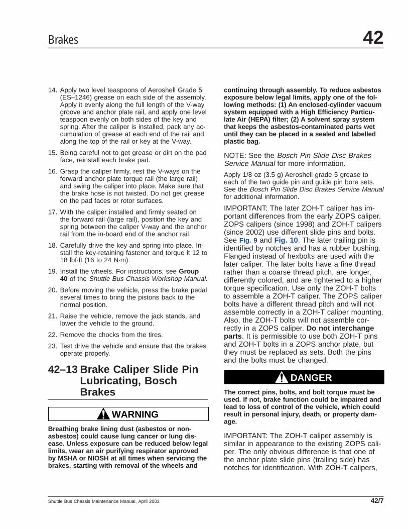
14. Apply two level teaspoons of Aeroshell Grade 5(ES–1246) grease on each side of the assembly.Apply it evenly along the full length of the V-waygroove and anchor plate rail, and apply one levelteaspoon evenly on both sides of the key andspring. After the caliper is installed, pack any ac-cumulation of grease at each end of the rail andalong the top of the rail or key at the V-way.
15. Being careful not to get grease or dirt on the padface, reinstall each brake pad.
16. Grasp the caliper firmly, rest the V-ways on theforward anchor plate torque rail (the large rail)and swing the caliper into place. Make sure thatthe brake hose is not twisted. Do not get greaseon the pad faces or rotor surfaces.
17. With the caliper installed and firmly seated onthe forward rail (large rail), position the key andspring between the caliper V-way and the anchorrail from the in-board end of the anchor rail.
18. Carefully drive the key and spring into place. In-stall the key-retaining fastener and torque it 12 to18 lbf·ft (16 to 24 N·m).
19. Install the wheels. For instructions, see Group40 of the Shuttle Bus Chassis Workshop Manual.
20. Before moving the vehicle, press the brake pedalseveral times to bring the pistons back to thenormal position.
21. Raise the vehicle, remove the jack stands, andlower the vehicle to the ground.
22. Remove the chocks from the tires.
23. Test drive the vehicle and ensure that the brakesoperate properly.
42–13 Brake Caliper Slide PinLubricating, BoschBrakes
WARNINGBreathing brake lining dust (asbestos or non-asbestos) could cause lung cancer or lung dis-ease. Unless exposure can be reduced below legallimits, wear an air purifying respirator approvedby MSHA or NIOSH at all times when servicing thebrakes, starting with removal of the wheels and
continuing through assembly. To reduce asbestosexposure below legal limits, apply one of the fol-lowing methods: (1) An enclosed-cylinder vacuumsystem equipped with a High Efficiency Particu-late Air (HEPA) filter; (2) A solvent spray systemthat keeps the asbestos-contaminated parts wetuntil they can be placed in a sealed and labelledplastic bag.
NOTE: See the Bosch Pin Slide Disc BrakesService Manual for more information.
Apply 1/8 oz (3.5 g) Aeroshell grade 5 grease toeach of the two guide pin and guide pin bore sets.See the Bosch Pin Slide Disc Brakes Service Manualfor additional information.
IMPORTANT: The later ZOH-T caliper has im-portant differences from the early ZOPS caliper.ZOPS calipers (since 1998) and ZOH-T calipers(since 2002) use different slide pins and bolts.See Fig. 9 and Fig. 10 . The later trailing pin isidentified by notches and has a rubber bushing.Flanged instead of hexbolts are used with thelater caliper. The later bolts have a fine threadrather than a coarse thread pitch, are longer,differently colored, and are tightened to a highertorque specification. Use only the ZOH-T boltsto assemble a ZOH-T caliper. The ZOPS caliperbolts have a different thread pitch and will notassemble correctly in a ZOH-T caliper mounting.Also, the ZOH-T bolts will not assemble cor-rectly in a ZOPS caliper. Do not interchangeparts . It is permissible to use both ZOH-T pinsand ZOH-T bolts in a ZOPS anchor plate, butthey must be replaced as sets. Both the pinsand the bolts must be changed.
DANGERThe correct pins, bolts, and bolt torque must beused. If not, brake function could be impaired andlead to loss of control of the vehicle, which couldresult in personal injury, death, or property dam-age.
IMPORTANT: The ZOH-T caliper assembly issimilar in appearance to the existing ZOPS cali-per. The only obvious difference is that one ofthe anchor plate slide pins (trailing side) hasnotches for identification. With ZOH-T calipers,
Brakes 42
Shuttle Bus Chassis Maintenance Manual, April 2003 42/7

install the solid pin (no bushing) only in the an-chor plate leading hole position. Install the pinwith the rubber bushing and notches only in theanchor plate trailing hole position. Tighten theleading-side pin first, then tighten the trailing-side pin.
Tighten ZOH-T bolts 93 to 107 lbf·ft (126 to 145N·m). Tighten ZOPS bolts 70 to 80 lbf·ft (95 to 108N·m).
42–14 ABS Tone RingsCleaning
CAUTIONAn accumulation of road salt, dirt, and debris onthe antilock braking system (ABS) tone rings andsensors can cause the ABS warning light to illumi-nate.
IMPORTANT: During winter months in areaswhere corrosive materials are used on the high-ways, periodically clean the underside of thevehicle to ensure proper ABS functioning. Thor-oughly clean the wheel/ABS sensor/tone ringareas, removing all corrosive materials.
42–15 Drum Brake Shoe RollerLubricating
WARNINGBreathing brake lining dust (asbestos or non-asbestos) could cause lung cancer or lung dis-ease. Unless exposure can be reduced below legallimits, wear an air purifying respirator approvedby MSHA or NIOSH at all times when servicing thebrakes, starting with removal of the wheels andcontinuing through assembly. To reduce asbestosexposure below legal limits, apply one of the fol-lowing methods: (1) An enclosed-cylinder vacuumsystem equipped with a High Efficiency Particu-late Air (HEPA) filter; (2) A solvent spray systemthat keeps the asbestos-contaminated parts wetuntil they can be placed in a sealed and labelledplastic bag.
1. Park the vehicle on a level surface. Shut downthe engine, set the parking brake, and chock thetires.
2. Raise the front or the rear axle and then placesafety stands under the frame or axle. Be surethat the stands will support the weight of the ve-hicle.
3. Remove the wheels and the brake drums.
f42235706/20/2002
12
34
1. Flanged Bolt2. Leading Pin
3. Trailing Pin4. Rubber Bushing
Fig. 9, ZOH-T Slide Pins and Bolts
f42235806/20/2002
13
32
1. Hexbolt2. Blue Patch3. Slide Pin
Fig. 10, ZOPS Slide Pins and Bolts
Brakes42
Shuttle Bus Chassis Maintenance Manual, April 200342/8

CAUTIONBefore you back off automatic slack adjusters, seethe slack adjuster manufacturer’s service informa-tion for instructions. Failure to do so could resultin damage to the slack adjusters.
4. Back off the slack adjusters.
5. Push down on the bottom brake shoe and then(by pulling on the roller-retaining clip) remove thebottom cam roller.
6. Lift the top brake shoe and then (by pulling onthe roller-retaining clip) remove the top camroller.
7. Clean the rollers, retaining clips, and the rollerpin recesses in the brake shoes thoroughly.
CAUTIONDo not apply grease to the outer diameters of therollers (where they contact the cam head).
8. Apply a good-quality, multi-purpose chassisgrease to the retaining clips, brake spider, andthe shoe rollers where they contact the brakeshoes.
9. One at a time, pull each brake shoe away fromthe cam and install the top and the bottom shoerollers.
10. Install the brake drums and the wheels.
DANGERDo not operate the vehicle until the brakes havebeen adjusted and checked for proper operation.To do so could result in inadequate or no brakingability, which could cause personal injury, ordeath, or property damage.
IMPORTANT: See the slack adjuster manufac-turer’s service information and adjust the brakesat the slack adjusters.
11. Remove the safety stands, lower the vehicle, andremove the chocks from the tires.
12. In a safe area, drive the vehicle and check forproper brake operation.
42–16 Air Dryer Inspecting,Midland
1. Check the reservoirs for moisture. A smallamount (a teaspoon or less) is normal. Largeramounts may mean that the desiccant needs tobe replaced. Check the mounting and connectinglines.
2. Tighten the fasteners attaching the air dryer tothe vehicle. Use the following torque values.
28 lbf·ft (38 N·m) for SAE grade 5, 3/8–16 fas-teners.
135 lbf·ft (183 N·m) for SAE grade 5, 5/8–11 fas-teners.
Check all air lines, fittings, and electrical connec-tions for damage, leakage, or looseness.
3. Replace damaged or leaking parts, and tightenloose fittings or electrical connections.
42–17 Air Dryer Desiccant andCoalescent FilterReplacing, Midland
NOTE: Desiccant change intervals may varyfrom vehicle to vehicle. Typical desiccant car-tridge life is three years. However, if experiencehas shown that extended or shortened life hasresulted on a particular installation, then the in-terval can be increased or decreased accord-ingly.
For air dryer desiccant and filter replacement, ordereither kit DQ6022 or kit DQ6026. The DQ6022 kitcontains 1 desiccant cartridge, 1 coalescent filter,and 2 O-rings. The DQ6026 kit contains 1 desiccantcartridge, 1 coalescent filter, and a heater cover. Fol-low the replacement procedure below.
Replacement1. Park the vehicle on a level surface. Shut down
the engine, set the parking brake, and chock thetires.
2. Completely drain all air reservoirs. Air pressuregauges should read 0 psi (0 kPa).
Brakes 42
Shuttle Bus Chassis Maintenance Manual, April 2003 42/9

3. Loosen the desiccant cartridge with a strapwrench at the base of the cartridge. Spin off thecartridge and discard it.
4. Remove the O-ring from the threaded neck anddiscard it.
5. Remove the coalescent filter and discard it.
IMPORTANT: Lubricate the new O-rings prior toinstallation.
6. Install the new small O-ring in the groove on thebottom of the new coalescent filter.
7. Insert the coalescent filter with the O-ring endgoing into the air dryer opening first. The end ofthe filter with the "X" will then be facing out.
8. Install the other new O-ring over the threadedneck of the desiccant cartridge.
9. Screw on the desiccant cartridge until resistanceis detected. Then, tighten the cartridge 1/4 to 3/4of a turn by hand.
Operational Check1. Start the engine and build air pressure to 120 psi
(827 kPa).
2. Listen for the purge valve to open and releaseair. A large volume of air will be expelled, fol-lowed by a slow flow of air lasting approximately30 seconds.
3. Shut down the engine and remove the chocksfrom the tires.
4. Perform the inspections in Maintenance Opera-tion 42–16 .
Brakes42
Shuttle Bus Chassis Maintenance Manual, April 200342/10

Title of Maintenance Operation (MOP) MOP Number
Drag Link Lubricating . . . . . . . . . . . . . . . . . . . . . . . . . . . . . . . . . . . . . . . . . . . . . . . . . . . . . . . . . . . . . . . 46–02
Power Steering Reservoir Fluid Level Checking. . . . . . . . . . . . . . . . . . . . . . . . . . . . . . . . . . . . . . . . . . . . 46–03
Power Steering Reservoir Fluid and Filter Changing . . . . . . . . . . . . . . . . . . . . . . . . . . . . . . . . . . . . . . . . 46–04
Steering Driveline Lubricating . . . . . . . . . . . . . . . . . . . . . . . . . . . . . . . . . . . . . . . . . . . . . . . . . . . . . . . . . 46–01
Steering Gear Lubricating. . . . . . . . . . . . . . . . . . . . . . . . . . . . . . . . . . . . . . . . . . . . . . . . . . . . . . . . . . . . 46–05
Steering 46Index, Alphabetical
Shuttle Bus Chassis Maintenance Manual, July 2000

46–01 Steering DrivelineLubricating
Wipe the grease fittings clean. See Fig. 1 . Using apressure gun, apply a lithium-based grease (NLGIgrade 2) sparingly to the universal joints and slip-jointsplines.
46–02 Drag Link Lubricating1. Using a clean rag, wipe the dirt from both grease
fittings on the drag link. See Fig. 2 .
2. Using a pressure gun, apply multipurpose chas-sis grease at the grease fittings until old greaseis forced out of the socket.
NOTE: Use multipurpose chassis grease NLGIgrade 1 (6% 12-hydroxy lithium stearate grease)or NLGI grade 2 (8% 12-hydroxy lithium stear-ate grease). The grade 2 chassis grease is pre-ferred.
1
2
34
51
6
6
10/05/94 f460516a
7
7
1. Pinch Bolt2. Universal Joint Shaft3. Bushing
4. Boot5. Boot Retainer
6. Prevailing Torque Locknut7. Grease Fitting
Fig. 1, Steering Driveline
Steering 46
Shuttle Bus Chassis Maintenance Manual, July 2000 46/1

46–03 Power SteeringReservoir Fluid LevelChecking
1. Clean around the power steering reservoir dip-stick (fill cap) with a clean rag, then remove thedipstick. See Fig. 3 .
WARNINGFill only with approved clean fluid. Do not mixfluid types. Any mixture or any unapproved fluidcould lead to seal deterioration and leaks. Fluidleakage could cause loss of power steering assist,possibly resulting in personal injury and propertydamage.
2. With the power steering fluid at operating tem-perature, check the fluid level on the dipstick. Ifbelow the "add" mark, add enough fluid to bringthe level up to the full mark on the dipstick. SeeTable 1 for approved power steering fluid.
Approved Power Steering Fluid
Fluid Type Approved Fluid
Automatic Transmission Fluid Dexron III*
* Use the same lubricant when assembling parts as is used in the powersteering system. See the Warning above.
Table 1, Approved Power Steering Fluid
3. Install the dipstick (fill cap) in the power steeringreservoir.
46–04 Power SteeringReservoir Fluid andFilter Changing
1. Remove the dipstick, 3/8-16 hexnut, and cover.See Fig. 3 .
2. Drain the power steering reservoir by disconnect-ing the power steering hydroboost hose from thereservoir. Keep the hose in an upright position toprevent drainage of fluid.
3. Catch the fluid from the reservoir in a drainbucket, then cap the reservoir port.
4. Lift out the spring and filter element.
5. Thoroughly clean the reservoir with a lint-freecloth.
f46092610/05/94
1 2
1. Grease Fitting2. Drag Link (pitman arm end shown)
Fig. 2, Steering Drag Link Lubricating
f460514a10/05/94
1
2
1. Power Steering Fluid Reservoir2. Steering Gear
Fig. 3, Power Steering Reservoir
Steering46
Shuttle Bus Chassis Maintenance Manual, July 200046/2
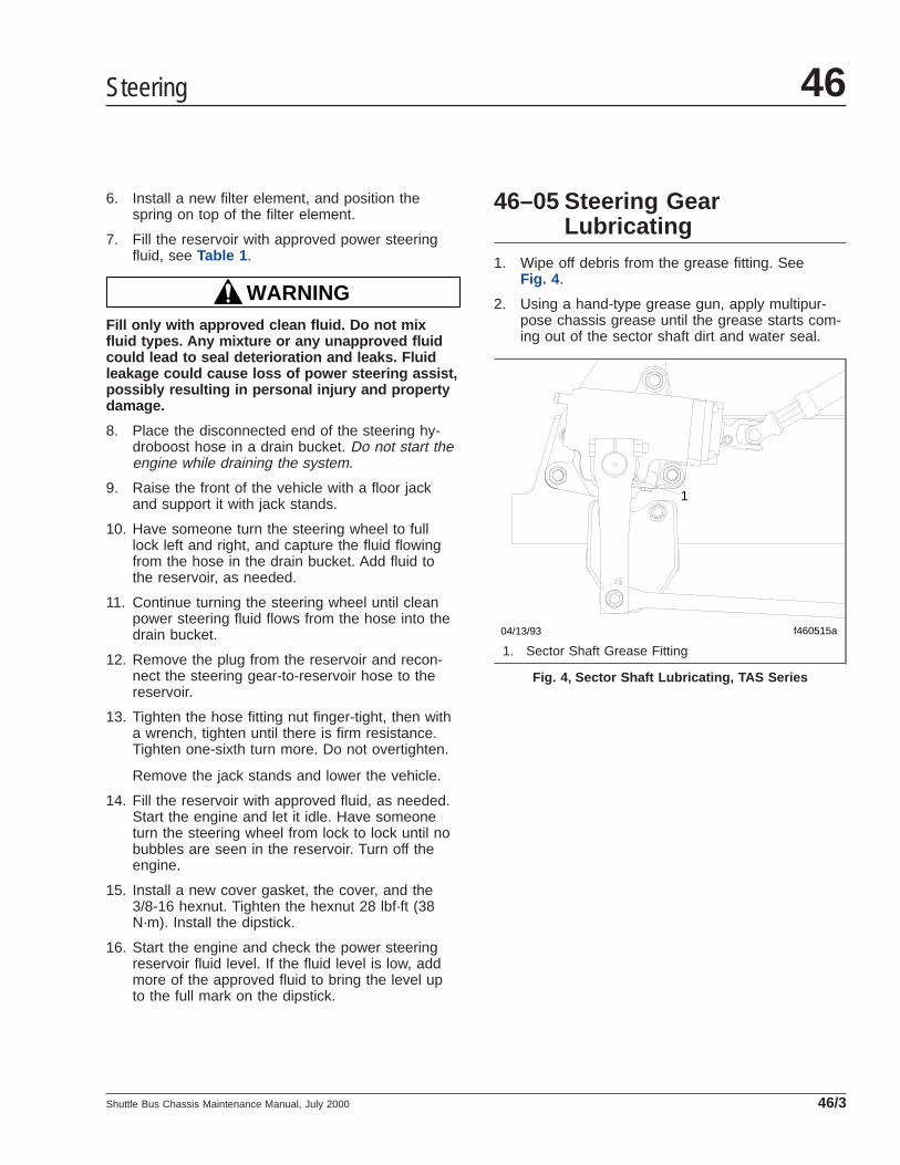
6. Install a new filter element, and position thespring on top of the filter element.
7. Fill the reservoir with approved power steeringfluid, see Table 1 .
WARNINGFill only with approved clean fluid. Do not mixfluid types. Any mixture or any unapproved fluidcould lead to seal deterioration and leaks. Fluidleakage could cause loss of power steering assist,possibly resulting in personal injury and propertydamage.
8. Place the disconnected end of the steering hy-droboost hose in a drain bucket. Do not start theengine while draining the system.
9. Raise the front of the vehicle with a floor jackand support it with jack stands.
10. Have someone turn the steering wheel to fulllock left and right, and capture the fluid flowingfrom the hose in the drain bucket. Add fluid tothe reservoir, as needed.
11. Continue turning the steering wheel until cleanpower steering fluid flows from the hose into thedrain bucket.
12. Remove the plug from the reservoir and recon-nect the steering gear-to-reservoir hose to thereservoir.
13. Tighten the hose fitting nut finger-tight, then witha wrench, tighten until there is firm resistance.Tighten one-sixth turn more. Do not overtighten.
Remove the jack stands and lower the vehicle.
14. Fill the reservoir with approved fluid, as needed.Start the engine and let it idle. Have someoneturn the steering wheel from lock to lock until nobubbles are seen in the reservoir. Turn off theengine.
15. Install a new cover gasket, the cover, and the3/8-16 hexnut. Tighten the hexnut 28 lbf·ft (38N·m). Install the dipstick.
16. Start the engine and check the power steeringreservoir fluid level. If the fluid level is low, addmore of the approved fluid to bring the level upto the full mark on the dipstick.
46–05 Steering GearLubricating
1. Wipe off debris from the grease fitting. SeeFig. 4 .
2. Using a hand-type grease gun, apply multipur-pose chassis grease until the grease starts com-ing out of the sector shaft dirt and water seal.
f460515a
1
04/13/93
1. Sector Shaft Grease Fitting
Fig. 4, Sector Shaft Lubricating, TAS Series
Steering 46
Shuttle Bus Chassis Maintenance Manual, July 2000 46/3

Title of Maintenance Operation (MOP) MOP Number
CNG Fuel Block Housing Draining . . . . . . . . . . . . . . . . . . . . . . . . . . . . . . . . . . . . . . . . . . . . . . . . . . . . . 47–05
CNG Fuel Leak Testing . . . . . . . . . . . . . . . . . . . . . . . . . . . . . . . . . . . . . . . . . . . . . . . . . . . . . . . . . . . . . 47–06
CNG Fuel Tank Visual Inspecting . . . . . . . . . . . . . . . . . . . . . . . . . . . . . . . . . . . . . . . . . . . . . . . . . . . . . . 47–07
CNG High-Pressure Fuel Filter Draining . . . . . . . . . . . . . . . . . . . . . . . . . . . . . . . . . . . . . . . . . . . . . . . . . 47–03
CNG High-Pressure Fuel Filter Replacing . . . . . . . . . . . . . . . . . . . . . . . . . . . . . . . . . . . . . . . . . . . . . . . . 47–08
CNG Low-Pressure Fuel Filter Draining. . . . . . . . . . . . . . . . . . . . . . . . . . . . . . . . . . . . . . . . . . . . . . . . . . 47–02
CNG Low-Pressure Fuel Filter Replacing . . . . . . . . . . . . . . . . . . . . . . . . . . . . . . . . . . . . . . . . . . . . . . . . 47–09
Diesel Fuel Tank Draining and Vent Checking . . . . . . . . . . . . . . . . . . . . . . . . . . . . . . . . . . . . . . . . . . . . . 47–01
Fuel/Water Separator Element Replacing . . . . . . . . . . . . . . . . . . . . . . . . . . . . . . . . . . . . . . . . . . . . . . . . 47–04
Inline Fuel Strainer Replacing, Cummins ISB02 Engine. . . . . . . . . . . . . . . . . . . . . . . . . . . . . . . . . . . . . . 47–10
Fuel 47Index, Alphabetical
Shuttle Bus Chassis Maintenance Manual, May 2005

47–01 Diesel Fuel TankDraining and VentChecking
Remove the plug or open the drain valve at the bot-tom of the fuel tank, and allow the tank to drain untilall traces of water and sediment have disappeared;install the plug or close the drain valve.
On earlier vehicles with a screw-on fuel cap, removethe fuel cap and clean it with solvent. Make sure thatthe fuel cap vent is open. Install the cap.
On vehicles with a quarter-turn fuel cap, check to besure that the vent line at the inboard side of the fueltank is clean and not plugged.
47–02 CNG Low-Pressure FuelFilter Draining
WARNINGCompressed natural gas is highly flammable. Seethe safety precautions listed in Chapter 10 of theShuttle Bus Chassis Operator’s Manual . Failure toobserve these precautions could lead to the igni-tion of the natural gas, which could cause severebodily harm, or death, or property damage.
Shut off the fuel supply at the fuel tanks.
Drain the fuel filters, which are mounted on the left-hand frame near the fuel regulator, by removing thedrain nut at the bottom of each filter housing.
47–03 CNG High-Pressure FuelFilter Draining
WARNINGCompressed natural gas is highly flammable. Seethe safety precautions listed in Chapter 10 of theShuttle Bus Chassis Operator’s Manual . Failure toobserve these precautions could lead to the igni-tion of the natural gas, which could cause severebodily harm, or death, or property damage.
Shut off the fuel supply at the fuel tanks.
WARNINGVent the system in a well-ventilated area andavoid sources of ignition such as sparks or ciga-rettes. Compressed natural gas is highly flam-mable. See the safety precautions listed in Chap-ter 10 of the Shuttle Bus Chassis Operator’sManual . Failure to observe these precautionscould lead to the ignition of the natural gas, whichcould cause severe bodily harm, or death, orproperty damage.
Vent the system.
Drain the fuel filters, which are mounted on the left-hand frame rail near the fuel regulator, by removingthe drain nut at the bottom of the filter housing.
47–04 Fuel/Water SeparatorElement Replacing
1. Park the vehicle on level surface. Shut down theengine, set the parking brake, and chock thetires.
2. Locate the fuel/water separator.
3. Replace the element.
4. Remove the chocks from the tires.
47–05 CNG Fuel Block HousingDraining
WARNINGCompressed natural gas is highly flammable. Seethe safety precautions listed in Chapter 10 of theShuttle Bus Chassis Operator’s Manual or Group47 of the Shuttle Bus Chassis Workshop Manual .Failure to observe these precautions could lead tothe ignition of the natural gas, which could causesevere bodily harm, or death, or property damage.
Shut off the fuel supply at the fuel tanks. Vent thesystem.
Remove the drain nut at the bottom of the engineinternal fuel filter, which is mounted on the left-handside of the engine.
Fuel 47
Shuttle Bus Chassis Maintenance Manual, May 2005 47/1

See the engine manufacturer’s operation and mainte-nance manual for further information.
47–06 CNG Fuel Leak Testing
WARNINGCompressed natural gas is highly flammable. Seethe safety precautions listed in Chapter 10 of theShuttle Bus Chassis Operator’s Manual or Group47 of the Shuttle Bus Chassis Workshop Manual .Failure to observe these precautions could lead tothe ignition of the natural gas, which could causesevere bodily harm, or death, or property damage.
Inspect and test the fuel tanks and the fuel lines. Usea natural gas detector to check for any leaks.
Replace leaking fuel tanks; repair or replace anylines or connections that are leaking. For proceduresand safety precautions, see Group 47 of the ShuttleBus Chassis Workshop Manual.
47–07 CNG Fuel Tank VisualInspecting
WARNINGCompressed natural gas is highly flammable. Seethe safety precautions listed in Chapter 10 of theShuttle Bus Chassis Operator’s Manual or Group47 of the Shuttle Bus Chassis Workshop Manual .
Failure to observe these precautions could lead tothe ignition of the natural gas, which could causesevere bodily harm, or death, or property damage.
Each fuel tank must be visually inspected at speci-fied intervals for external damage and deterioration.The inspection must be performed by a qualified per-son, in accordance with the manufacturer’s estab-lished reinspection criteria and Compressed Gas As-sociation documents.
Perform this maintenance procedure as indicated inthe maintenance interval chart in this manual. SeeTable 1 for the remedies to any damage found onthe tank. See Group 47 of the Shuttle Bus ChassisWorkshop Manual for tank repair procedures.
47–08 CNG High-Pressure FuelFilter Replacing
WARNINGCompressed natural gas is highly flammable. Seethe safety precautions listed in Chapter 10 of theShuttle Bus Chassis Operator’s Manual or Group47 of the Shuttle Bus Chassis Workshop Manual .Failure to observe these precautions could lead tothe ignition of the natural gas, which could causesevere bodily harm, or death, or property damage.
The high pressure fuel filter is located inside of theleft-hand frame rail, near the rear of the fuel tank.
CNG Tank Visual Inspection
Damage Condition Remedy
Abrasion on the FiberglassWrap
Less Than 0.010 Inch (0.4 mm) Deep No repair needed.
More Than 0.010 Inch (0.4 mm) But LessThan 0.030 Inch (1.2 mm) Deep
Repair.
More Than 0.030 Inch (1.2 mm) Deep Replace tank.
Cuts in the Fiberglass Wrap Less Than 0.020 Inch (0.8 mm) Deep No repair needed.
More Than 0.020 Inch (0.8 mm) But LessThan 0.030 Inch (1.2 mm) Deep
Repair if less than 8 inches (200 mm) long.
More Than 0.030 Inch (1.2 mm) Deep Replace tank.
Dents on Metal Ends Less Than 0.060 Inch (1.6 mm) Deep No repair needed
More Than 0.060 Inch (1.6 mm) Deep Replace tank.
Gouges on Metal Ends Bare Metal is Exposed Replace tank.
Fuel47
Shuttle Bus Chassis Maintenance Manual, May 200547/2
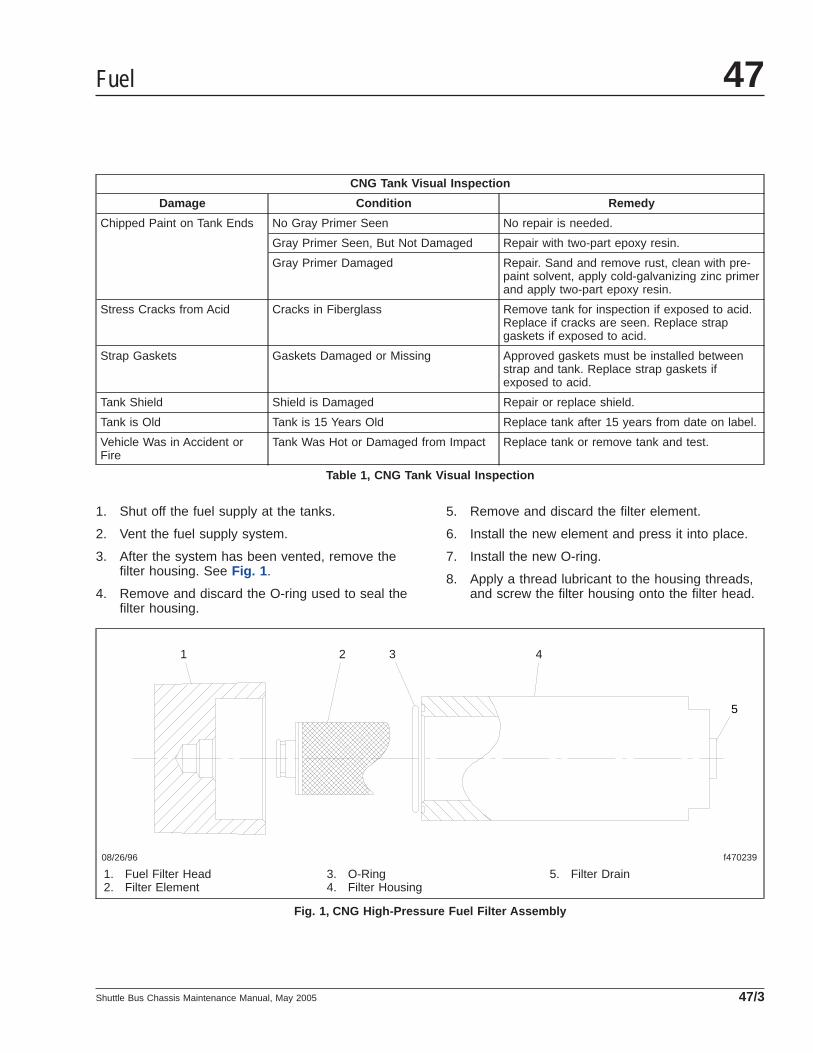
CNG Tank Visual Inspection
Damage Condition Remedy
Chipped Paint on Tank Ends No Gray Primer Seen No repair is needed.
Gray Primer Seen, But Not Damaged Repair with two-part epoxy resin.
Gray Primer Damaged Repair. Sand and remove rust, clean with pre-paint solvent, apply cold-galvanizing zinc primerand apply two-part epoxy resin.
Stress Cracks from Acid Cracks in Fiberglass Remove tank for inspection if exposed to acid.Replace if cracks are seen. Replace strapgaskets if exposed to acid.
Strap Gaskets Gaskets Damaged or Missing Approved gaskets must be installed betweenstrap and tank. Replace strap gaskets ifexposed to acid.
Tank Shield Shield is Damaged Repair or replace shield.
Tank is Old Tank is 15 Years Old Replace tank after 15 years from date on label.
Vehicle Was in Accident orFire
Tank Was Hot or Damaged from Impact Replace tank or remove tank and test.
Table 1, CNG Tank Visual Inspection
1. Shut off the fuel supply at the tanks.
2. Vent the fuel supply system.
3. After the system has been vented, remove thefilter housing. See Fig. 1 .
4. Remove and discard the O-ring used to seal thefilter housing.
5. Remove and discard the filter element.
6. Install the new element and press it into place.
7. Install the new O-ring.
8. Apply a thread lubricant to the housing threads,and screw the filter housing onto the filter head.
08/26/96 f470239
1 2 3 4
5
1. Fuel Filter Head2. Filter Element
3. O-Ring4. Filter Housing
5. Filter Drain
Fig. 1, CNG High-Pressure Fuel Filter Assembly
Fuel 47
Shuttle Bus Chassis Maintenance Manual, May 2005 47/3

9. Check for leaks using a natural gas detector.
10. Tighten the filter housing.
11. Turn the fuel supply on at the tanks.
47–09 CNG Low-Pressure FuelFilter Replacing
WARNINGCompressed natural gas is highly flammable. Seethe safety precautions listed in Chapter 10 of theShuttle Bus Chassis Operator’s Manual or Group47 of the Shuttle Bus Chassis Workshop Manual .Failure to observe these precautions could lead tothe ignition of the natural gas, which could causesevere bodily harm, or death, or property damage.
The low pressure fuel filter is located inside of theleft-hand frame rail, near the center of the fuel tank.
Turn the valve counter-clockwise to close the filterdrain.
1. Shut off the fuel supply at the tanks.
2. Vent the fuel supply system.
3. After the system has been vented, remove thefilter bowl. See Fig. 2 . Using a 26-mm wrench,remove the bowl nut. Then remove the bowl, theelement retainer, and the filter element.
NOTE: Be sure that the O-ring is positionedproperly inside of the filter head.
4. Install the new element, the element retainer, thebowl, and the bowl nut.
5. Turn the fuel supply on at the tanks.
47–10 Inline Fuel StrainerReplacing, CumminsISB02 Engine
NOTE: Vehicles with a Cummins ISB02 enginehave an inline fuel strainer located on the left-hand side of the engine.
1. Remove the brackets at each end of the fuelstrainer.
2. Remove the P-clip.
IMPORTANT: The fuel flow arrow on the fuelstrainer must be pointed toward the front of thevehicle.
3. Remove the strainer, and replace it with a newone.
4. Install the P-clip.
5. Install the brackets on each end of the fuelstrainer.
1
2
3
4
5
08/23/96 f470238
1. Fuel Filter Head2. Filter Element3. Element Retainer
4. Filter Bowl5. Bowl Nut
Fig. 2, CNG Low-Pressure Fuel Filter Assembly
Fuel47
Shuttle Bus Chassis Maintenance Manual, May 200547/4
Title of Maintenance Operation (MOP) MOP Number
Exhaust System Inspecting (Noise Emission Control). . . . . . . . . . . . . . . . . . . . . . . . . . . . . . . . . . . . . . . . 49–01
Exhaust 49Index, Alphabetical
Shuttle Bus Chassis Maintenance Manual, July 2000

49–01 Exhaust SystemInspecting (NoiseEmission Control)
NOTE: In addition to the maintenance interval inthis manual, inspect the exhaust system if thevehicle has a noticeable increase in noise levelat any time. Replace parts that show leakage,wear, or damage.
1. Check the muffler body, muffler outlet stack, muf-fler shield, and inlet tubes, for leakage, dents,corrosion, or holes in the muffler.
2. Inspect the exhaust pipe for leakage, wear, ordamage; replace with new parts, if needed. Donot reuse wide-band clamps. Once a clamp isremoved, it must be replaced.
On Caterpillar and Cummins engines, check forleakage at the V-type clamp that attaches theexhaust pipe to the turbocharger exhaust outlet.If leakage exists, tighten the nut on the V-typeclamp 50 lbf·in (560 N·cm). Using a plastic ham-mer, tap around the clamp, then tighten again to50 lbf·in (560 N·cm). If leakage persists, replacethe clamp.
3. Check for leakage at each wide-band exhaustclamp, see Fig. 1 . If leakage exists, tighten thenuts on Torca "Torctite" exhaust clamps 40 to 60lbf·ft (54 to 81 N·m). If leakage persists, install anew wide-band exhaust clamp. See Section49.00 of the Shuttle Bus Chassis WorkshopManual for procedures.
f490005a10/05/94
Fig. 1, Wide-Band Exhaust Clamp
Exhaust 49
Shuttle Bus Chassis Maintenance Manual, July 2000 49/1

Title of Maintenance Operation (MOP) MOP Number
Coolant Level Sensor Cleaning. . . . . . . . . . . . . . . . . . . . . . . . . . . . . . . . . . . . . . . . . . . . . . . . . . . . . . . . 54–01
Electrical System Checking. . . . . . . . . . . . . . . . . . . . . . . . . . . . . . . . . . . . . . . . . . . . . . . . . . . . . . . . . . . 54–02
Ground Cables Checking and Cleaning. . . . . . . . . . . . . . . . . . . . . . . . . . . . . . . . . . . . . . . . . . . . . . . . . . 54–03
Electrical, Instruments, and Controls 54Index, Alphabetical
Shuttle Bus Chassis Maintenance Manual, April 2003

54–01 Coolant Level SensorCleaning
1. Drain enough coolant from the radiator to exposethe coolant level sensor.
2. Disconnect wire 173 from the sensor in the ra-diator surge tank. Remove the sensor from thesurge tank.
3. Using a fine-grit sandpaper, clean the sensor un-til the metal is exposed. Clean the tapped holewith a wire brush.
4. Install the sensor (do not seal the sensor threadswith tape), and reconnect wire 173. Fill the cool-ing system to the proper level.
5. Start the engine. The LOW WTR light and warn-ing buzzer should be off. If the light and buzzerare on, replace the sensor.
54–02 Electrical SystemChecking
Cab1. Uncover the electrical panel by removing the fas-
teners. See Fig. 1 .
2. Check the wiring harness for movement thatcould strain the electrical connections. Installmore clamps on the harness if needed.
3. Check all of the wiring for chafing, kinks, anddiscolored insulation. Find the cause of any prob-lems, then repair, replace, or reroute the wires asneeded.
4. Check that all of the relays and circuit breakersare firmly seated in their mounting plates.
5. Check the turn-signal flasher (if so equipped).See Fig. 1 . Make sure that the two male andfemale connectors are firmly connected. Checkthat the flasher fuse is firmly seated in theholder.
6. Check the cigarette lighter. Look inside of thesocket for signs of overheating (discoloration ormelting) caused by misuse of the lighter socket.
7. Test the electric horn. If it does not work, turn theadjustment screw in or out until the horn works.If the horn still does not work, check the wiring. Ifthe wiring is not damaged, replace the horn.
8. Check connectors on the right side of the front-wall, below the radiator surge tank. See Fig. 2.Check the terminals for tightness, damage, cor-rosion, or dirt.
f54084310/05/94
1
1. Flasher
Fig. 1, Under-Dash Electrical Panel
f54084410/05/94
1
2
1
1. Electrical Connectors2. Magnetic Switch
Fig. 2, Right Side of the Frontwall
Electrical, Instruments, and Controls 54
Shuttle Bus Chassis Maintenance Manual, April 2003 54/1

9. Check the seven-way trailer cable plug at theback of the cab. Make sure that all of the pinsare tight and free of dirt and grease.
Chassis1. Check the main wiring harness. Check the wiring
insulation for damage from chafing or heat. Alsocheck for kinks. Reroute, repair, or replace thewires as needed.
2. Check connections at the starter, starter relays,alternator, and chassis grounds.
3. Check all of the tie straps for breakage or dam-age. Replace any broken or cracked tie straps.
CAUTIONDo not use flat-strip aluminum tie straps for hold-ing electrical wiring. The sharp edges on these tiestraps may cause breaks in the wire insulation,allowing the aluminum tie strap to make contactwith the wire. This could cause a short circuit anddamage to the wiring.
4. Check the temperature sending units on the ax-les and transmission. Check for damaged wiresand loose connectors.
54–03 Ground CablesChecking and Cleaning
Check that the ground cables are clean, undamaged,and tight. If necessary, disconnect them and cleanthe mating surfaces with a soda solution. Then, con-nect them securely. Spray the ground cable connec-tions with dielectric red enamel. See Table 1 for ap-proved part numbers.
Approved Dielectric Grease and Red Enamel
Material Part Number
Dielectric Grease 48-02349-000
Dielectric Red EnamelSpray
MMM 1602 IVI Spray-Sealer (Spray-On B-6-665)
Table 1, Approved Dielectric Grease and Red Enamel
Electrical, Instruments, and Controls54
Shuttle Bus Chassis Maintenance Manual, April 200354/2

Title of Maintenance Operation (MOP) MOP Number
Air Conditioner Checking, R-134a Refrigerant System. . . . . . . . . . . . . . . . . . . . . . . . . . . . . . . . . . . . . . . 83–01
Heater and Air Conditioner 83Index, Alphabetical
Shuttle Bus Chassis Maintenance Manual, April 2003

83–01 Air ConditionerChecking, R-134aRefrigerant System
Preliminary Checks1. Park the vehicle on a level surface. Shut down
the engine, set the parking brake, and chock thetires.
2. Make sure that the refrigerant compressor drivebelt is not damaged and that it is correctly ten-sioned. Also check the tightness of the compres-sor mounting fasteners. For instructions andtorque values, see Group 01 of the Shuttle BusChassis Workshop Manual.
3. Using a feeler gauge, check for correct clutchclearance. For instructions, see Group 83 of theShuttle Bus Chassis Workshop Manual.
4. Inspect the compressor clutch coil wire. Checkthe connector for damage or looseness. Replacethe wire if it is damaged.
5. Check for broken, burst, or cut hoses. Also checkfor loose fittings on all parts.
WARNINGWear eye protection when using compressed airto clean parts, as permanent harm to eyes couldresult from flying debris.
6. Check for a build-up of road debris on the con-denser fins. Using a whiskbroom and air pres-sure, or a spray of soapy water, carefully cleanoff the condenser; be careful not to bend the fins.
Cooling Checking1. Start the engine and set engine speed at 1500
rpm. Close the doors and windows.
IMPORTANT: When outside temperature andhumidity are high it will take longer to cool theinterior, especially if fresh-air vents are leftopen.
2. Turn on the air conditioner; set the controls atmaximum cooling and blower speed.
3. Allow the system to run for at least 10 minutes(longer on hot and humid days).
4. Check air flow from the vents. If there is notenough air flow, check the air intake vent forblockage and the blower motor for proper opera-tion.
If the air flow is not cold enough, see Group 83of the Shuttle Bus Chassis Workshop Manual.
5. Carefully feel the system lines.
• The compressor discharge line should feelhot.
• The condenser inlet line should be notice-ably warmer than the outlet line.
• The line from the condenser should feelwarm.
• The inlet and outlet lines of the receiver-drier should be about the same tempera-ture.
• The line from the receiver-drier to theevaporator should feel warm.
• The line from the evaporator to the com-pressor should feel cold.
NOTE: Oily spots on the lines or at the fittingscould indicate a system leak.
Refrigerant CheckingIf equipped with a moisture indicator sight glass,check the color of the moisture indicator. See Fig. 1 ,Ref. 1.
If the moisture indicator is a deep cobalt blue, therefrigerant charge is dry. If the indicator is not blue,the system is contaminated with water; recover therefrigerant, replace the receiver-drier, evacuate thesystem, and add a full refrigerant charge.
Heater and Air Conditioner 83
Shuttle Bus Chassis Maintenance Manual, April 2003 83/1

12/16/93 f250177b
12
1. Moisture Indicator Sight Glass2. Receiver-Drier Sight Glass
Fig. 1, Receiver-Drier
Heater and Air Conditioner83
Shuttle Bus Chassis Maintenance Manual, April 200383/2