Embed Size (px)
Citation preview

SHRED 'N' VAC®
Operator's Manual
MODEL ES-210Serial Number 05001001 - 05999999
X75300072003/03
X7531130200
WARNING DANGERRead rules for safe operation and all instructions carefully. ECHO provides thisOperator's Manual which must be read and understood for proper and safe operation.
2
INTRODUCTION
Welcome to the ECHO family. This ECHO product was designed and manufactured to provide long life and on-the-jobdependability. Read and understand this manual. You will find it easy to use and full of helpful operating tips andSAFETY messages.
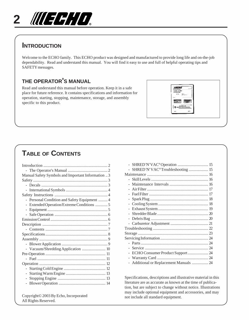
THE OPERATOR'S MANUALRead and understand this manual before operation. Keep it in a safeplace for future reference. It contains specifications and information foroperation, starting, stopping, maintenance, storage, and assemblyspecific to this product.
Copyright© 2003 By Echo, IncorporatedAll Rights Reserved.
TABLE OF CONTENTS
Introduction ............................................................... 2- The Operator's Manual ....................................... 2
Manual Safety Symbols and Important Information .. 3Safety ......................................................................... 3
- Decals ................................................................. 3- International Symbols ......................................... 4
Safety Instructions .................................................... 4- Personal Condition and Safety Equipment ......... 4- Extended Operation/Extreme Conditions ............ 5- Equipment ........................................................... 5- Safe Operation .................................................... 6
Emission Control ........................................................ 6Description ................................................................ 7
- Contents ............................................................. 7Specifications ............................................................. 8Assembly ................................................................... 9
- Blower Application ............................................. 9- Vacuum/Shredding Application ....................... 10
Pre-Operation ........................................................... 11- Fuel ................................................................... 11
Operation ................................................................. 12- Starting Cold Engine ......................................... 12- Starting Warm Engine ....................................... 13- Stopping Engine ............................................... 13- Blower Operation .............................................. 14
- SHRED 'N' VAC® Operation .............................. 15- SHRED 'N' VAC® Troubleshooting ................... 15
Maintenance ............................................................ 16- Skill Levels ........................................................ 16- Maintenance Intervals ...................................... 16- Air Filter ............................................................ 17- Fuel Filter .......................................................... 17- Spark Plug ......................................................... 18- Cooling System ................................................. 18- Exhaust System ................................................. 19- Shredder Blade .................................................. 20- Debris Bag ........................................................ 20- Carburetor Adjustment ..................................... 21
Troubleshooting ...................................................... 22Storage ..................................................................... 23Servicing Information ............................................... 24
- Parts .................................................................. 24- Service .............................................................. 24- ECHO Consumer Product Support .................... 24- Warranty Card .................................................. 24- Additional or Replacement Manuals ................ 24
Specifications, descriptions and illustrative material in thisliterature are as accurate as known at the time of publica-tion, but are subject to change without notice. Illustrationsmay include optional equipment and accessories, and maynot include all standard equipment.

3SHRED 'N' VAC®
OPERATOR'S MANUAL
IMPORTANTThe enclosed message providesinformation necessary for the protectionof the unit.
NOTEThis enclosed message provides tips foruse, care and maintenance of the unit.
SAFETY
DECALS
Locate these safety decals on your unit. Make sure the decals arelegible and that you understand and follow the instructions on them. Ifa decal cannot be read, a new one can be ordered from your ECHOdealer. See PARTS ORDERING instructions for specific information.
IMPORTANT NOTE
P/N 89016006361
P/N 89016003360
Hot Decal (near muffler)
General Warning Decal (located on top of blower housing)
71 Category IIdB(A
)
Measured at 50 ft. (15m) per ANSI B175.2
Sound Label (located on blower housing)P/N 89016009461
P/N X508000140
MANUAL SAFETY SYMBOLS AND IMPORTANT INFORMATION
Throughout this manual and on the product itself, you will find safetyalerts and helpful, informational messages preceded by symbols or keywords. The following is an explanation of those symbols and keywords and what they mean to you.
This symbol accompanied by the words WARNING andDANGER calls attention to an act or condition that can lead toserious personal injury to operator and bystanders.
The circle with the slash symbol means whatever is shownwithin the circle is prohibited.
4
WARNING DANGERSHRED ‘N’ VAC® users risk injury to themselves and others if the SHRED ‘N’ VAC® is used improperly and/orsafety precautions are not followed. Proper clothing and safety gear must be worn when operating SHRED ‘N’VAC®.
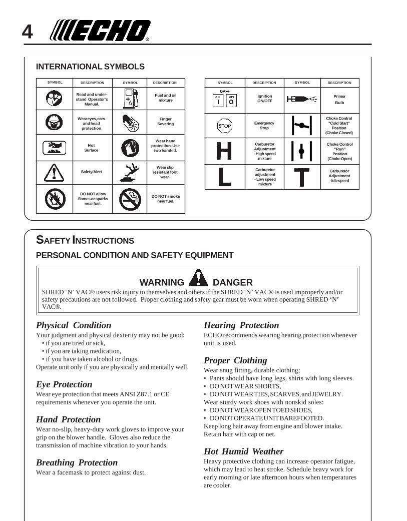
INTERNATIONAL SYMBOLS
SYMBOL
CarburetorAdjustment- Idle speed
CarburetorAdjustment- High speed
mixture
EmergencyStop
Carburetoradjustment- Low speed
mixture
IgnitionON/OFF
Primer
Bulb
Choke Control"Cold Start"
Position(Choke Closed)
Choke Control"Run"
Position(Choke Open)
DESCRIPTION SYMBOL DESCRIPTION
HotSurface
Read and under-stand Operator's
Manual.
Wear eyes, earsand head
protection
Fuel and oilmixture
FingerSevering
Safety/Alert
Wear handprotection. Use
two handed.
DO NOT smokenear fuel.
DO NOT allowflames or sparks
near fuel.
Wear slipresistant foot
wear.
SYMBOL DESCRIPTION SYMBOL DESCRIPTION
SAFETY INSTRUCTIONS
PERSONAL CONDITION AND SAFETY EQUIPMENT
Physical ConditionYour judgment and physical dexterity may not be good:
• if you are tired or sick,• if you are taking medication,• if you have taken alcohol or drugs.
Operate unit only if you are physically and mentally well.
Eye ProtectionWear eye protection that meets ANSI Z87.1 or CErequirements whenever you operate the unit.
Hand ProtectionWear no-slip, heavy-duty work gloves to improve yourgrip on the blower handle. Gloves also reduce thetransmission of machine vibration to your hands.
Breathing ProtectionWear a facemask to protect against dust.
Hearing ProtectionECHO recommends wearing hearing protection wheneverunit is used.
Proper ClothingWear snug fitting, durable clothing;• Pants should have long legs, shirts with long sleeves.• DO NOT WEAR SHORTS,• DO NOT WEAR TIES, SCARVES, and JEWELRY.Wear sturdy work shoes with nonskid soles:• DO NOT WEAR OPEN TOED SHOES,• DO NOT OPERATE UNIT BAREFOOTED.Keep long hair away from engine and blower intake.Retain hair with cap or net.
Hot Humid WeatherHeavy protective clothing can increase operator fatigue,which may lead to heat stroke. Schedule heavy work forearly morning or late afternoon hours when temperaturesare cooler.
5SHRED 'N' VAC®
OPERATOR'S MANUAL
EQUIPMENT
• Check unit for loose/missing nuts, bolts and screws. Tightenand/or replace as needed.
• Inspect fuel lines, tank and area around carburetor for fuel leaks. DONOT operate unit if leaks are found.
• Do not use blower if any part is missing or damaged.
• Do not use any attachment, accessory or replacement part unless it isrecommended in this Operator's Manual.
• Avoid contact during and immediately after operation. Always keepexhaust area clear of flammable debris. Allow the engine and mufflerto completely cool before performing any maintenance activity.
EXTENDED OPERATION/EXTREME CONDITIONS
Vibration and ColdIt is believed that a condition called Raynaud’s Phenomenon, whichaffects the fingers of certain individuals, may be brought about byexposure to vibration and cold. Exposure to vibration and cold maycause tingling and burning sensations, followed by loss of color andnumbness in the fingers. The following precautions are stronglyrecommended, because the minimum exposure, which might trigger theailment, is unknown.
• Keep your body warm, especially the head, neck, feet, ankles, hands,and wrists.
• Maintain good blood circulation by performing vigorous armexercises during frequent work breaks, and also by not smoking.
• Limit the hours of operation. Try to fill each day with jobs whereoperating the unit or other hand-held power equipment is notrequired.
• If you experience discomfort, redness, and swelling of the fingersfollowed by whitening and loss of feeling, consult your physicianbefore further exposing yourself to cold and vibration.
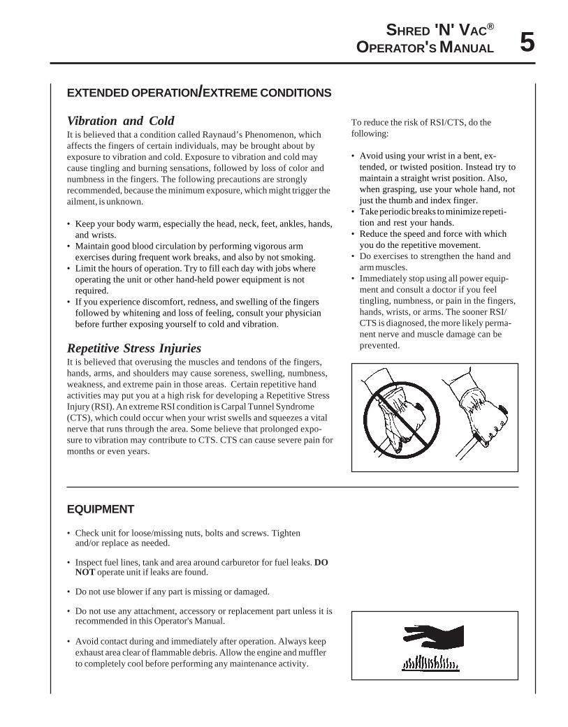
Repetitive Stress InjuriesIt is believed that overusing the muscles and tendons of the fingers,hands, arms, and shoulders may cause soreness, swelling, numbness,weakness, and extreme pain in those areas. Certain repetitive handactivities may put you at a high risk for developing a Repetitive StressInjury (RSI). An extreme RSI condition is Carpal Tunnel Syndrome(CTS), which could occur when your wrist swells and squeezes a vitalnerve that runs through the area. Some believe that prolonged expo-sure to vibration may contribute to CTS. CTS can cause severe pain formonths or even years.
To reduce the risk of RSI/CTS, do thefollowing:
• Avoid using your wrist in a bent, ex-tended, or twisted position. Instead try tomaintain a straight wrist position. Also,when grasping, use your whole hand, notjust the thumb and index finger.
• Take periodic breaks to minimize repeti-tion and rest your hands.
• Reduce the speed and force with whichyou do the repetitive movement.
• Do exercises to strengthen the hand andarm muscles.
• Immediately stop using all power equip-ment and consult a doctor if you feeltingling, numbness, or pain in the fingers,hands, wrists, or arms. The sooner RSI/CTS is diagnosed, the more likely perma-nent nerve and muscle damage can beprevented.

6
IMPORTANT ENGINE INFORMATIONENGINE FAMILY: 3EHXS.0214EA DISPLACEMENT: 21.2 ccEMISSION COMPLIANCE PERIOD: 300 HoursTHIS ENGINE MEETS U.S. EPA PH 2 EMISSION REGULATIONSFOR SMALL NONROAD ENGINES. REFER TO OWNER'SMANUAL FOR MAINTENANCE SPECIFICATIONS ANDADJUSTMENTS.
SAFE OPERATION
WARNING DANGERDo not operate this product indoors or in inadequately ventilatedareas. Engine exhaust contains poisonous emissions and can causeserious injury or death.
Read the Manuals• Provide all users of this equipment with the Operator’s Manual and
Safety Manual for instructions on Safe Operation.
Clear the Work Area• Review area to be cleared. Look for potential hazards such as stones
or metal objects.• Spectators and fellow workers must be warned, and children and
animals prevented from coming nearer than 15 m (50 ft.) while the unitis in use.
• Do not point blower at people or animals.• Take wind conditions into account: avoid open doors and windows.
Keep A Firm Grip• Hold handles with fingers together encircling handles.
Keep A Solid Stance• Maintain footing and balance at all times. Do not stand on slippery,
uneven or unstable surfaces. Do not work in odd positions or onladders.
• Do not perform Maintenance or Assembly procedures with enginerunning.
Noise Control• Follow local noise regulations on sound
levels and hours of operations. Use onlyduring appropriate hours.
• Never use a higher speed setting thennecessary to perform a task. The higherthe engine speed the louder the blowernoise.
• Be a good neighbor.
Avoid Hot Surfaces• During operation, the muffler or catalytic
muffler and surrounding cover maybecome extremely hot. Avoid contactduring and immediately after operation.Always keep exhaust area clear offlammable debris. Allow the engine andmuffler to completely cool before perform-ing any maintenance activity.
EMISSION CONTROL
EPA Phase 2The emission control system for this engine is EM (Engine Modification).
Emission Control Label (located on Engine) (EXAMPLE ONLY, information on label varies by FAMILY).
PRODUCT EMISSION DURABILITYThe 300 hour emission durability compliance period is the time span selected by the manufacturer certifying theengine emissions output meets applicable emissions regulations, provided that approved maintenance proceduresare followed as listed in the Maintenance Section of this manual.

7SHRED 'N' VAC®
OPERATOR'S MANUAL
1
2
3
5
6
78
9
10
1112
4
13
14
DESCRIPTION
CONTENTS__ 1 - Power Head__ 1 - Straight Pipe__ 1 - Pipe with Nozzle__ 1 - SHRED 'N' VAC® Suction Tube__ 1 - Elbow Pipe__ 1 - Debris Bag__ 1 - Operator's Manual__ 1 - Warranty Registration Card__ 1 - ECHO Emissions and Warranty Statement__ 1 - T-Wrench__ 1 - Echo Power Blend TM 2-stroke oil sample
1. STOP SWITCH - "SLIDE SWITCH" mounted on top of handle. Push forward to start and run. Slide back to stop.2. THROTTLE TRIGGER - Spring loaded to return to idle when released. During acceleration, press trigger gradually
for best operating technique.3. SPARK PLUG - Provides spark to ignite fuel mixture.4. SPARK ARRESTOR - CATALYTIC MUFFLER / MUFFLER -The muffler or catalytic muffler controls exhaust noise
and emission. The spark arrestor screen prevents hot, glowing particles of carbon from leaving the muffler. Keepexhaust area clear of flammable debris.
5. RECOIL STARTER HANDLE - Pull recoil handle slowly until starter engages, then quickly and firmly. Whenengine starts, return handle slowly. DO NOT let handle snap back or damage to unit will occur.
6. SIDE HANDLE - Provides grip for right hand when vacuuming.7. FUEL TANK CAP - Covers and seals fuel tank.8. AIR CLEANER - Contains replaceable air filter element.9. HOUSING COVER - Covers blade area and activates safety interlock switch when closed. Engine will not run if
safety switch is not activated.10. THROTTLE POSITION LEVER - Pull back to increase engine speed. Friction washers maintain throttle lever
setting.11. SHOULDER STRAP -Secures debris bag to shoulder.12. VACUUM PIPE - Sucks in materials to be shredded.13. DEBRIS BAG - Collects shredded material.
15
16
8
14. BLOWER PIPES - Twist lock design.15. PRIMER BULB - Pumping primer bulb before starting engine draws fresh fuel from the fuel tank, priming the
carburetor for starting. Pump primer bulb until fuel is visible and flows freely in the clear fuel tank return line. Pumpbulb an additional 4 or 5 times.
16. CHOKE - Choke is located on the side of the air cleaner. Move choke lever to "COLD START" ( ) to close choke
for cold starting. Move choke lever to "RUN" ( ) position to open choke.
SPECIFICATIONS
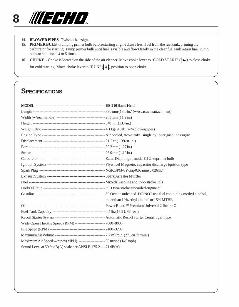
MODEL ----------------------------------------------------- ES-210 Hand Held
Length ------------------------------------------------------- 330 mm (13.0 in.) (w/o vacuum attachment)
Width (w/rear handle) ------------------------------------- 285 mm (11.2 in.)
Height ------------------------------------------------------- 340 mm (13.4 in.)
Weight (dry) ------------------------------------------------ 4.1 kg (9.0 lb.) w/o blowerpipes)
Engine Type ------------------------------------------------ Air cooled, two-stroke, single cylinder gasoline engine
Displacement ----------------------------------------------- 21.2 cc (1.39 cu. in.)
Bore ---------------------------------------------------------- 32.2 mm (1.27 in.)
Stroke -------------------------------------------------------- 26.0 mm (1.10 in.)
Carburetor -------------------------------------------------- Zama Diaphragm, model C1U w/primer bulb
Ignition System -------------------------------------------- Flywheel Magneto, capacitor discharge ignition type
Spark Plug -------------------------------------------------- NGK BPM-8Y Gap 0.65 mm (0.026 in.)
Exhaust System -------------------------------------------- Spark Arrestor Muffler
Fuel ---------------------------------------------------------- Mixed (Gasoline and Two-stroke Oil)
Fuel/Oil Ratio ----------------------------------------------- 50:1 two-stroke air cooled engine oil
Gasoline ----------------------------------------------------- 89 Octane unleaded. DO NOT use fuel containing methyl alcohol,
more than 10% ethyl alcohol or 15% MTBE.
Oil ------------------------------------------------------------ Power Blend TM Premium Universal 2-Stroke Oil
Fuel Tank Capacity ---------------------------------------- 0.5 lit. (16.9 US fl. oz.)
Recoil Starter System -------------------------------------- Automatic Recoil Starter Centrifugal Type
Wide Open Throttle Speed (RPM) ----------------------- 7000 - 9000
Idle Speed (RPM) ------------------------------------------ 2400 - 3200
Maximum Air Volume -------------------------------------- 7.7 m3/min. (271 cu. ft./min.)
Maximum Air Speed w/pipes (MPH) -------------------- 65 m/sec (145 mph)
Sound Level at 50 ft. dB(A) scale per ANSI B 175.2 --- 71 dB(A)

9SHRED 'N' VAC®
OPERATOR'S MANUAL
ASSEMBLY
WARNING DANGERNever perform maintenance or assembly procedures with enginerunning, or serious personal injury may result.
BLOWER APPLICATION
Install Blower Pipes
1. Align grooves in straight pipe with pegs on blower housing andslide pipe onto housing.
2. Turn straight pipe clockwise to lock into place.
3. Align grooves in fan head nozzle with pegs on straight pipe andslide fan head nozzle onto straight pipe.
4. Turn fan head nozzle clockwise to lock into place.
VACUUM/SHREDDING APPLICATION
Install Vacuum Tube and Bag Assembly
1. Turn knob (A) counter clockwise until hinged housing cover isfree to open for vacuum tube installation.
2. While holding housing cover open. Install vacuum tube intoblower housing with bevel end facing downward and securevacuum tube with clamp (B). Clamp fits under slotted guides (C).
NOTEEngine will not start/operate unless safety interlock switch (D) isactivated by the vacuum tube.
3. Remove blower pipe assembly from unit.
A
B
C
D
10
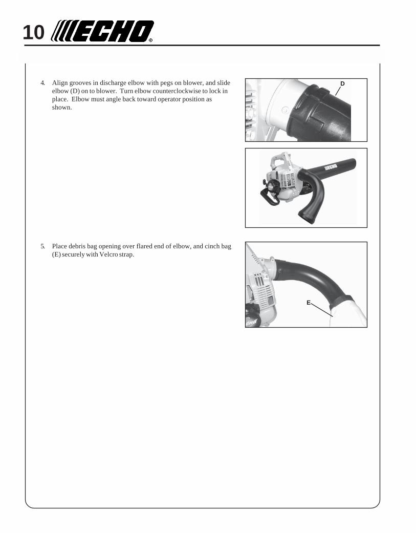
4. Align grooves in discharge elbow with pegs on blower, and slideelbow (D) on to blower. Turn elbow counterclockwise to lock inplace. Elbow must angle back toward operator position asshown.
5. Place debris bag opening over flared end of elbow, and cinch bag(E) securely with Velcro strap.
D
E
11SHRED 'N' VAC®
OPERATOR'S MANUAL
IMPORTANTSpilled fuel is a leading cause of hydrocar-bon emissions. Some states may requirethe use of automatic fuel shut-off contain-ers to reduce fuel spillage. Contact yourECHO dealer for ordering information.
After Refueling• Wipe any spilled fuel from the unit.• Move at least 3 m (10 ft.) from refueling
location before starting the engine.
After use• DO NOT store a unit with fuel in its tank.
Leaks can occur. Return unused fuel to anapproved fuel storage container.
Storage - Fuel storage laws vary by locality.Contact your local government for the lawsaffecting your area. As a precaution, store fuelin an approved, airtight container. Store in awell-ventilated, unoccupied building, awayfrom sparks and flames. Do not store fuellonger than 30 days.
IMPORTANTStored fuel ages. Do not mix more fuelthan you expect to use in thirty (30) days,ninety (90) days when a fuel stabilizer isadded.
IMPORTANTStored two-stroke fuel may separate.ALWAYS shake fuel container thor-oughly before each use.
PRE-OPERATION
FUELFuel RequirementsGasoline - Use 89 Octane [R+M/2] (mid grade or higher) gasolineknown to be good quality. Gasoline may contain up to 15% MTBE(methyl tertiary-butyl ether). Gasohol containing methyl (wood)alcohol is NOT approved.
Two Stroke Oil - A two-stroke engine oil meeting ISO-L-EGD (ISO/CD 13738) and J.A.S.O. FC Standards must be used. Echo brandpremium Power Blend TM Universal 2-Stroke Oil meets these stan-dards. Engine problems due to inadequate lubrication caused byfailure to use an ISO-L-EGD and J.A.S.O. FC certified oil, such asEcho premium Power Blend TM, will void the two-stroke enginewarranty. (Emission related parts only are covered for two years,regardless of two-stroke oil used, per the statement listed in theEmission Defect Warranty Explanation.)
IMPORTANTEcho premium Power Blend TM Universal 2-Stroke Oil may bemixed at 50:1 ratio for application in all Echo engines sold in thepast regardless of ratio specified in those manuals.
Mixing Instructions1. Fill an approved fuel container with half of the required amount
of gasoline.2. Add the proper amount of 2-stroke oil to gasoline.3. Close container and shake to mix oil with gasoline.4. Add remaining gasoline and remix.5. Install fuel container cap and wipe any spilled fuel from
container and surrounding area.
Handling Fuel
WARNING DANGERFuel is VERY flammable. Use extreme care when mixing, storingor handling or serious personal injury may result.• Use an approved fuel container.• DO NOT smoke near fuel.• DO NOT allow flames or sparks near fuel.• Fuel tanks/cans may be under pressure. Always loosen fuel
caps slowly allowing pressure to equalize.• NEVER refuel a unit when the engine is HOT!• NEVER refuel a unit with the engine running.• DO NOT fill fuel tanks indoors. ALWAYS fill fuel tanks
outdoors over bare ground.• Securely tighten fuel cap after refueling.• Inspect for fuel leakage. If fuel leakage is found, do not start or
operate unit until leakage is repaired.

12
OPERATION
STARTING COLD ENGINE
1. Stop SwitchMove stop switch button (A) away from the STOP position.
2. Throttle Position LeverMove throttle position lever (B) midway between idle and fullthrottle positions.
3. ChokeMove choke (C) to Cold Start ( ) Position.
4. Primer BulbPump primer bulb (D) until fuel is visible and flows freely in theclear fuel tank return line. Pump bulb an additional 4 or 5 times.
IMPORTANTRecoil starter: Use short pulls - only 45 ~ 60 cm (18 ~ 24 in.) ofrope for starting. Do not allow the rope to snap back in. Alwayshold the unit firmly.
5. Recoil StarterPlace the unit on a flat, clear area. Firmly grasp throttle grip withleft hand and rapidly pull recoil starter handle/rope (E) untilengine fires (5 pulls maximum).
6. ChokeAfter engine fires (or 5 pulls), move choke lever (C) to “Run” ( )position, then pull starter handle/rope until engine starts andruns. Allow unit to warm up at idle for several minutes.
NOTEIf engine does not start with choke in “Run” position after 5 pulls,repeat instructions.
7. After engine warm up, gradually depress throttle trigger toincrease engine RPM to operating speed.
A
B
C
D
E

13SHRED 'N' VAC®
OPERATOR'S MANUAL
STARTING WARM ENGINEThe starting procedure is the same as Cold Start except DO NOT closethe choke.
1. Stop SwitchMove stop switch button (A) away from the STOP position.
2. Throttle Position LeverMove throttle position lever (B) forward to idle position.
3. Primer BulbPump primer bulb (D) until fuel is visible and flows freely in theclear fuel tank return line. Pump bulb an additional 4 or 5 times.
4. Recoil StarterPlace the unit on a flat, clear area. Firmly grasp throttle grip withleft hand and rapidly pull recoil starter handle/rope (E) untilengine fires.
IMPORTANTRecoil starter: Use short pulls - only 45 ~ 60 cm (18 ~ 24 in.) ofrope for starting. Do not allow the rope to snap back in. Alwayshold the unit firmly.
NOTEIf engine does not start after 5 pulls, use Cold Start Procedure.
STOPPING ENGINE
1. Throttle Trigger/Throttle Position LeverRelease throttle trigger (F). Move throttle position lever (B)forward to idle position and allow engine to return to idle beforeshutting engine off.
2. Stop SwitchMove stop switch (A) to “STOP” position.
WARNING DANGERIf engine does not stop when stop switch is moved to STOPposition, close choke - COLD START position - to stall engine.Have your ECHO dealer repair stop switch before using bloweragain.
AB
A
F
E
B

14
BLOWER OPERATION
WARNING DANGERAlways wear safety glasses, hearing protection and a face filtermask or serious personal injury may result.
Do not point the blower pipe in the direction of people or pets.
Never operate unit without either housing cover grill or vacuumtube installed on unit securely, otherwise bodily harm may result.
Read the Safety Section carefully.
IMPORTANTTo avoid engine damage due to over-revving, do not block blowerpipe.
1. Use only during appropriate hours.
2. Allow the engine to warm up at a fast idle for a few minutes.
3. Control engine speed with throttle trigger (A), or for continuoususe, set engine speed with throttle position lever (B). Rotatethrottle position lever forward for lower speed, back for higherspeed.
4. Use lower speed to blow debris from hard surfaces.
5. Additional speed may be necessary to clean debris, snow, etc.from lawns and flowerbeds.
NOTENever use a higher speed setting than necessary to perform a task.Remember, the higher the engine speed, the louder the blowernoise. Minimize dust by using blower at lower speeds. Keep debrison your property.Be Smart - be a good neighbor.
B
A
15SHRED 'N' VAC®
OPERATOR'S MANUAL
SHRED ‘N’ VAC® OPERATION
WARNING DANGERFlying debris hazard. Never operate unit as a vacuum unlessdischarge elbow is installed and debris bag is securely cinched toelbow. Failure to follow instructions can result in serious injuries.
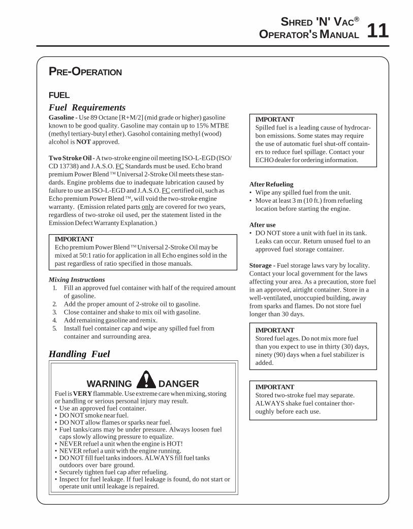
1. Adjust debris bag strap to support bag on operator’s shoulder.Bag must not be folded at intake area, or intake will clog. Furtheradjustment may be necessary as the debris bag fills and becomesheavier.
2. Grip top handle with left hand, and rear handle with right hand.Keep unit to your right side so hot exhaust will be directed awayfrom you.
3. Operate unit with beveled end of tube facing downward. Keeptube opening close to material being vacuumed for best results.
NOTEVacuum action works best at higher engine speeds. Avoid usingvacuum in areas where rocks or other large, hard debris may bevacuumed into unit. Clear these areas with blower first, blowinglight debris into a pile. Use attachment to vacuum pile.
4. Empty bag when debris level reaches intake opening. To emptybag, move stop switch to “Stop” position, and wait for blower tostop running. Loosen Velcro strap at elbow and slide bag offelbow. Open other end of bag, and empty contents. Close bag,and reattach to blower. Secure bag with Velcro strap.
SHRED 'N' VAC® TROUBLESHOOTING
Problem Cause Remedy
Unit runs, but doesn’t vacuum orhas poor suction
Elbow or debris bag clogged Check elbow and debris bag, and clearas needed. Make sure bag is not foldedover at intake during use.
Obstructions in vacuum tube Check vacuum tube, and removeobstructions.
Unit stopped suddenly duringvacuuming, and now starter won’twork
Object stuck in fan housing area
Unit jams repeatedly during use Material being vacuumed too big ortoo hard for blades to shred
Use vacuum for leaves and smalltwigs, maximum 1/4” diameter x 3”long.
Vacuum tube difficult to install orremove from unit
Tube/housing fit tight. Apply small amount of soapy water toend of tube to ease assembly orremoval. Turns tube 1/4 turn to loosenfor removal.
Remove vacuum tube and check fanarea. Remove object.

16
MAINTENANCE
Your ECHO blower is designed to provide many hours of trouble free service. Regular scheduled maintenance will helpyour blower achieve that goal. If you are unsure or are not equipped with the necessary tools, you may want to take yourunit to an ECHO Service Dealer for maintenance. To help you decide whether you want to DO-IT-YOURSELF or have theECHO Dealer do it, each maintenance task has been graded. If task is not listed, see your ECHO Dealer for repairs.
SKILL LEVELLevel 1 = Easy to do. Most required tools come with unit.Level 2 = Moderate difficulty. Some specialized tools may be required.Level 3 = Experience required. Specialized tools are required. Echo recommends
that the unit be returned to your ECHO dealer for service.
ECHO offers REPOWERTM Maintenance Kits and Parts to make your maintenance job easier. Just below each taskheading are listed the various part numbers required for that task. See your ECHO dealer for these parts.
MAINTENANCE INTERVALS
/TNENOPMOCMETSYS
ECNANETNIAMERUDECORP
D'QERLLIKSLEVEL
YLIADRO
EROFEBESU
YREVELEUFER
3SHTNOM
09ROSRUOH
6SHTNOM
072ROSRUOH
YLRAEY
serudecorPecnanetniaMrelaeDohcEdednemmoceR
roterubraC ecalpeR/naelC/tcepsnI 3 C/I )1(R
troPtsuahxErednilyC nobraceD/naelC/tcepsnI 3 C/I
serudecorPecnanetniaMflesruoY-tI-oD
retliFriA ecalpeR/naelC/tcepsnI 1 C/I *R
ekohC naelC/tcepsnI 2 C/I
retliFleuF ecalpeR/tcepsnI 1 I *R
eniLleuF ecalpeR/tcepsnI 1 I *R/I
metsySgnilooC naelC/tcepsnI 2 C/I
rotserrAkrapSrelffuM ecalpeR/tcepsnI 2 *R/I
epoRretratSlioceR naelC/tcepsnI 1 C/I *R/I
skaeLleuF ecalpeR/tcepsnI 1 I I *R/I
gulPkrapS naelC/tcepsnI 2 C/I *R
stloB/stuN/swercS ecalpeR/nethgiT/tcepsnI 1 *R/I
SEDOCRETTELERUDECORPECNANETNIAM NAELC=C,ECALPER=R,TCEPSNI=I:-ETONTNATROPMI deriuqerfoycneuqerfehtenimretedlliwecneirepxeruoydnaesulautcA.mumixameranwohsslavretniemiT
.ecnanetniam:SETONERUDECORPECNANETNIAM
)1( .deriuqersishtnom6yrevegninaelc,esuremusnoCroF.sruoh006retfaesulaicremmoCrofderiuqereblliwtnemecalpeR* .noitcepsnignirudraewroegamadfognidnifehtnodesaberaecalperotsnoitadnemmocerllA

17SHRED 'N' VAC®
OPERATOR'S MANUAL
AIR FILTER
Level 1.
Tools required: 25-50 mm (1-2 in.) cleaning brush.
Parts required: Air Filter
NOTEClean daily.
1. Close choke (Cold Start Position [ ]). This prevents dirt fromentering the carburetor throat when the air filter is removed.Brush accumulated dirt from the air cleaner area.
2. Remove the air cleaner cover. Clean and inspect the element fordamage. If element is fuel soaked and very dirty, replace.
3. If element can be cleaned and reused, be certain
• still fits the cavity in the air cleaner cover.• is installed with the original side out.
FUEL FILTER
Level 1.
Tools required: 200-250 mm (8-10 in.) length of wire with one endbent into a hook. clean rag, funnel, and an approvedfuel container.
Parts required: Fuel Filter
WARNING DANGERFuel is VERY flammable. Use extreme care when mixing, storing, orhandling.
1. Use a clean rag to remove loose dirt from around fuel cap andempty fuel tank.
2. Use the “fuel line hook” to pull the fuel line and filter from thetank.
3. Remove the filter from the line and install the new filter.

18
COOLING SYSTEM CLEANING
Level 2.
Tools required: 25-50 mm (1-2 in.) cleaning brush, 3 mm hex wrench,cross head screwdriver
Parts Required: None, if you are careful.
IMPORTANTTo maintain proper engine operating temperatures, cooling air mustpass freely through the cylinder fin area. This flow of air carriescombustion heat away from the engine.
Overheating and engine seizure can occur when:• Air intakes are blocked, preventing cooling air from reaching the
cylinder.• Dust and grass build up on the outside of the cylinder. This build-up
insulates the engine and prevents the heat from leaving.
Removal of cooling passage blockages or cleaning of cooling fins isconsidered “Normal Maintenance.” Any failure attributed to lack ofmaintenance is not warranted.
Cleaning Grill
1. Remove accumulated debris from crankcase intake grill above thefuel tank.
SPARK PLUG
Level 2.
Tools required: T-Wrench, Feeler gauge
Parts Required: REPOWERTM Tune-Up Kit P/N 90074
1. Remove spark plug and check for fouling, worn and roundedcenter electrode.
2. Clean the plug or replace with a new one. DO NOT sand blast toclean. Remaining sand will damage engine.
3. Adjust spark plug gap by bending outer electrode.
4. Tighten spark plug to 145-155 kg/cm (125-135 in. lb.).0.65 mm(0.026 in.)

19SHRED 'N' VAC®
OPERATOR'S MANUAL
EXHAUST SYSTEM
Spark Arrestor Screen
Level 2.
Tools required: Cross Head Screwdriver, 3 mm Hex Wrench, softmetal brush
Parts Required: Spark arrestor screen P/N 14586240630, Gasket P/N14586642031
IMPORTANTCarbon deposits in muffler will cause a drop in engine output andoverheating. Spark arrestor screen must be checked periodically.
1. Remove spark plug lead and spark plug.
2. Remove four 3 mm hex screws, side handle and recoil starter.
3. Remove engine cover (five screws), pull cover away from engine.Clean cylinder fins to allow cooling air to pass freely.
4. Remove screen cover (A, B), gasket (C), and spark arrestor screen(D) from muffler body. Replace screen if plugged with carbondeposits.
5. Install spark arrestor screen, gasket, and covers.
6. Loosely reassemble engine cover, recoil starter, and side handle.
7. Tighten all screws securely.
8. Install spark plug and spark plug lead.
A
B
CD
Cleaning Cylinder Fins
1. Remove spark lead and spark plug.
2. Remove four 3 mm hex screws, side handle and recoil starter.
3. Remove engine cover (five screws), pull cover away from engine.Loosely install spark plug to prevent dirt from entering cylinder.Clean cylinder fins to allow cooling air to pass freely.
4. Remove spark plug and loosely reassemble engine cover, recoilstarter, and side handle.
5. Tighten all screws securely.
6. Install spark plug and spark plug lead.
20
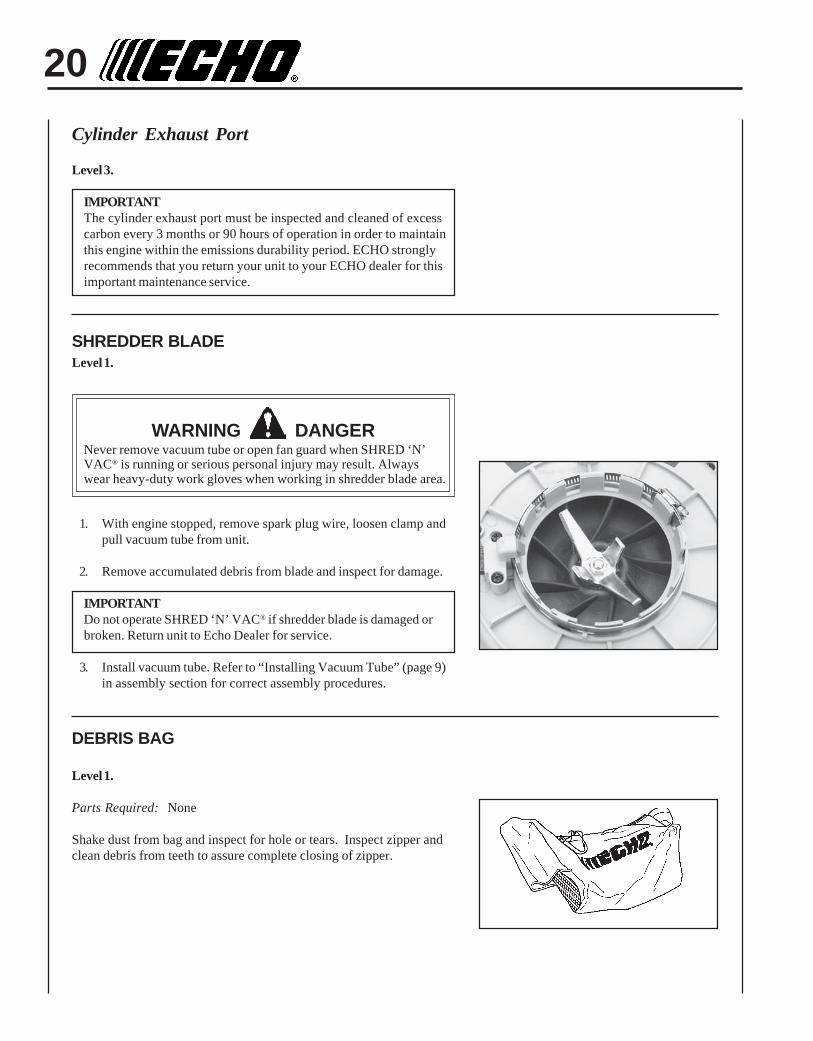
SHREDDER BLADELevel 1.
WARNING DANGERNever remove vacuum tube or open fan guard when SHRED ‘N’VAC® is running or serious personal injury may result. Alwayswear heavy-duty work gloves when working in shredder blade area.
1. With engine stopped, remove spark plug wire, loosen clamp andpull vacuum tube from unit.
2. Remove accumulated debris from blade and inspect for damage.
IMPORTANTDo not operate SHRED ‘N’ VAC® if shredder blade is damaged orbroken. Return unit to Echo Dealer for service.
3. Install vacuum tube. Refer to “Installing Vacuum Tube” (page 9)in assembly section for correct assembly procedures.
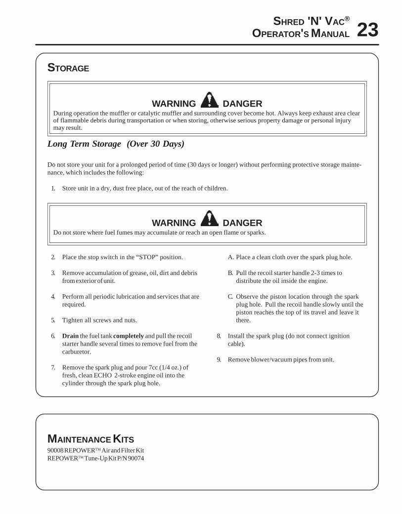
DEBRIS BAG
Level 1.
Parts Required: None
Shake dust from bag and inspect for hole or tears. Inspect zipper andclean debris from teeth to assure complete closing of zipper.
Cylinder Exhaust Port
Level 3.
IMPORTANTThe cylinder exhaust port must be inspected and cleaned of excesscarbon every 3 months or 90 hours of operation in order to maintainthis engine within the emissions durability period. ECHO stronglyrecommends that you return your unit to your ECHO dealer for thisimportant maintenance service.

21SHRED 'N' VAC®
OPERATOR'S MANUAL
CARBURETOR ADJUSTMENT
Engine Break-InNew engines must be operated a minimum duration of two tanks of fuelbreak-in before carburetor adjustments can be made. During the break-in period your engine performance will increase and exhaust emissionswill stabilize. Idle speed can be adjusted as required.
High Altitude AdjustmentHigh altitude adjustment is not required for proper operation of thisengine.
Level 2.
Tools required: Screwdriver, tachometer (Echo P/N 99051130017)
Parts required: None.
NOTEEvery unit is run at the factory and the carburetor is set in compli-ance with emission regulations. This carburetor does not haveacceleration adjustment needle.
1. Before adjusting the carburetor, clean or replace the air filter andspark arrestor screen and install blower pipes.
2. Start engine and run for several minutes to reach operatingtemperature.
3. Stop engine. Turn red HI speed needle (A) CCW (counterclockwise) to stop.
4. Idle Speed Adjustment with tachometer.•Start engine and turn “idle” speed adjustment screw (B) to idleRPM found on page 8 “Specifications” section of this manual.
5. Accelerate to full throttle for 2-3 seconds to clear excess fuel fromengine then return to idle. Accelerate to full throttle to check forsmooth transition from idle to full throttle. If engine stops orstalls after full warm up, return the unit to your authorized ECHOdealer for repair.
6. Check HI speed RPM at W.O.T. (Wide Open Throttle). HI speedRPM should be set to specifications found on page 8 “Specifica-tions” of this manual.
7. Check idle speed and reset if necessary.
A
B

22
WARNING DANGERFuel vapors are extremely flammable and may cause fire and/or explosion. Never test for ignition spark by ground-ing spark plug against cylinder, otherwise serious personal injury may result.
TROUBLESHOOTING
TRAHCGNITOOHSELBUORT
melborP kcehC sutatS esuaC ydemeR
-sknarcenignE/drahstrats
t'nseodtrats
roterubractaleuF roterubractaleufoN deggolcreniartsleuFdeggolcenilleuF
roterubraC
ecalperronaelCecalperronaelC
relaedohcEruoyeeS
rednilyctaleuF rednilyctaleufoN roterubraC relaedohcEruoyeeS
leufhtiwtewrelffuM hcirooterutxiMleuF ekohcnepOretlifriaecalper/naelC
roterubractsujdArelaedohcEruoyeeS
dnetakrapSeriwgulpfo
krapsoN ffohctiwspotSmelborplacirtcelE
hctiwskcolretnI
NOothctiwsnruTrelaedohcEruoyeeSrelaedohcEruoyeeS
gulptakrapS krapsoN tcerrocnipagkrapSnobrachtiwderevoC
leufhtiwdeluoFevitcefedgulP
).ni620.0(mm56.ottsujdAecalperronaelCecalperronaelC
gulpecalpeR
,snurenignEroseidtub
tonseodetarelecca
ylreporp
retlifriA ytridretlifriA raewlamroN ecalperronaelC
retlifleuF ytridretlifleuF seudiser/stnanimatnoC nileuf
ecalpeR
tnevleuF deggulptnevleuF leufniseudiser/stnanimatnoC ecalperronaelC
gulPkrapS nrow/ytridgulP raewlamroN ecalperrotsujdadnanaelC
roterubraC tnemtsujdareporpmI noitarbiV tsujdA
metsySgnilooC metsysgnilooCdeggulp/ytrid
ninoitarepodednetxEsnoitacolytsud/ytrid
naelC
neercSrotserrAkrapS neercsrotserrakrapSdeggulp
raewlamroN ecalpeR
seodenignEknarcton
A/N A/N melborpenignelanretnI relaedohcEruoyeeS
,snurenignEt'nseodrewolb
sirokrownevenu/kaew
epiprewolB deggolcepiP sirbedfopu-dliuB golcnU
esoolepiP noitarbiV nethgiT
degamadepiP esusiM/raeW ecalpeR
23SHRED 'N' VAC®
OPERATOR'S MANUAL
STORAGE
WARNING DANGERDuring operation the muffler or catalytic muffler and surrounding cover become hot. Always keep exhaust area clearof flammable debris during transportation or when storing, otherwise serious property damage or personal injurymay result.
Long Term Storage (Over 30 Days)
Do not store your unit for a prolonged period of time (30 days or longer) without performing protective storage mainte-nance, which includes the following:
1. Store unit in a dry, dust free place, out of the reach of children.
WARNING DANGERDo not store where fuel fumes may accumulate or reach an open flame or sparks.
2. Place the stop switch in the “STOP” position.
3. Remove accumulation of grease, oil, dirt and debrisfrom exterior of unit.
4. Perform all periodic lubrication and services that arerequired.
5. Tighten all screws and nuts.
6. Drain the fuel tank completely and pull the recoilstarter handle several times to remove fuel from thecarburetor.
7. Remove the spark plug and pour 7cc (1/4 oz.) offresh, clean ECHO 2-stroke engine oil into thecylinder through the spark plug hole.
A. Place a clean cloth over the spark plug hole.
B. Pull the recoil starter handle 2-3 times todistribute the oil inside the engine.
C. Observe the piston location through the sparkplug hole. Pull the recoil handle slowly until thepiston reaches the top of its travel and leave itthere.
8. Install the spark plug (do not connect ignitioncable).
9. Remove blower/vacuum pipes from unit.
MAINTENANCE KITS90008 REPOWERTM Air and Filter KitREPOWERTM Tune-Up Kit P/N 90074

DEALER?Call
1-800-432-ECHOor
www.echo-usa.com
CONSUMER PRODUCTSUPPORT
1-800-673-15588:30 - 4:30 Mon - Fri C.S.T.
ECHO, INCORPORATED400 Oakwood Road
Lake Zurich, IL 60047www.echo-usa.com
Available Parts Catalog
ES-210 Serial Number 05001001 - 05999999 Part Number 99922203283
SERVICING INFORMATION
PARTSGenuine ECHO Parts and ECHO REPOWER™ Parts and Assemblies foryour ECHO products are available only from an Authorized ECHODealer. When you do need to buy parts always have the ModelNumber and Serial Number of the unit with you. You can find thesenumbers on the engine housing. For future reference, write them in thespace provided below.
Model Number _____________ Serial Number ____________
SERVICEAn Authorized ECHO Service Dealer must perform Service of thisproduct during the warranty period. For the name and address of theAuthorized ECHO Service Dealer nearest you, ask your retailer or call:1-800-432-ECHO (3246). Dealer information is also available on ourWeb Site. When presenting your unit for Warranty service/repairs,proof of purchase is required.
ECHO CONSUMER PRODUCT SUPPORTIf you require assistance or have questions concerning the application,operation or maintenance of this product you may call the ECHOConsumer Product Support Department at 1-800-673-1558 from 8:30 amto 4:30 pm (Central Standard Time) Monday through Friday. Beforecalling, please know the model and serial number of your unit to helpyour Consumer Product Support Representative.
WARRANTY REGISTRATIONYou may register your Echo equipment using the warranty registrationcard or register on-line at www.echo-usa.com. Registering provides adirect link between you and Echo if we find it necessary to contactyou.
ADDITIONAL OR REPLACEMENT MANUALSSafety Manuals in English/Spanish or English/French are available, free of charge, from your ECHO dealer or atwww.echo-usa.com.Operator’s and Parts Manuals are available by:• Downloading free from www.echo-usa.com• Purchasing from your Echo Dealer.• Manuals are available by sending a written request stating the model number and serial number of your Echo unit,
part number of the manual, your name and address, and mail to the address below.Safety Videos are available from your Echo dealer. A $5.00 shipping charge will be required for each video.