Embed Size (px)
Citation preview

www.weforma.com14.4.2016
Mega-Line WE-M 0,25Mega-Line WE-M 0,35
SVF
m
Dec
eler
atio
n Te
chno
logy
Shock Absorbers
ONLINECalculation + 2D / 3D CAD Download

www.weforma.com14.4.2016
Enlarged piston:- Max. +400% energy- Max. -50% costs / Nm
Piston: - Hardened, aluminium- titanium-nitride coated
Extended life cycle:- Nitrated guidance system- Piston rod: hardened stainless steel- Special seals + oils
ProSurf:- Surface protection against corrosion
Benefits
Special models::- Stainless steel: V4A/DIN1.4404/AISL 316L- For pressure chambers up to 7 bar- USDA-H 1 compliant for food industry- Cleanroom
Stop caps:
A:- Standard from POM- Increased protection of the impact surface
AP2:- Longer life time compared to stop cap AP and plastic cap A
AP:- 40% noise reduction due to PU- Increased protection of the impact surface
AS:- From hardened steel- For side forces and difficult operating conditions
Temperature:Standard: -20°C - ...+80°Low-temperature: -50°C-...+60°CHigh-temperature: 0°C-...+120°C
Integrated stop:- Max. security- Easy installation

www.weforma.com14.4.2016
A
AP
AS
AP2
GW* A B C øD øE (A) øE (AP /AP2)
øE (AS) F (A) F(AP /AP2)
F (AS) K L SW SW1 SW2 F (B) øM H
mm mm mm mm mm mm mm mm mm mm mm mm mm mm mm mm mm mmWE-M 0,25 M 14 x 1 97 78 2,5 4 10 10 10 105 105 105 4,5 5 13 17 - 109 20 33WE-M 0,35 M 16 x 1 97 78 2,5 4 10 10 10 105 105 105 4,5 6 14 19 - 109 22 33
mm Nm/HB (max.) Nm/h (max.) min. - max.kg min. - max.kg min. - max.kg min. - max.kg min. - max.kg
WE-M 0,25 14 30 50.000 - 1,6 - 1500 - - -WE-M 0,35 14 35 52.500 - 6,5 - 1750 - - -
StrokeEnergy absoption Effective Mass
Constant load* -0 (very soft) -1 (soft) -2 (medium) -3 (hard) -4 (very hard)
Series Code Threads Example
0,25 L M 14x1,5 WE-M 0,25L0,25 UF 1/2-20 UNF WE-M 0,25UF0,25 UC 9/16-18 UNeF WE-M 0,25UC
0,35 D M 15x1 WE-M 0,35D0,35 L M 16x1,5 WE-M 0,35L
Series Code Threads Example
0,25 M 14x1 WE-M 0,25-VA0,25 L M 14x1,5 WE-M 0,25L-VA
0,35 M16x1 WE-M 0,35-VA0,35 L M 16x1,5 WE-M 0,35L-VA
PERFOMANCE
DIMENSIONS
SPECIAL THREAD - from stock STAINLESS STEEL - from stock
Technical data at + 20°C
*A: Plastic / AP: Soft Touch / AS: Steel

www.weforma.com14.4.2016
Weight 0,25: 0,05 kg0,35: 0,07 kg
Impact speed WE-M: 0,08 - 6,0 m/s
Return spring force 0,25 / 0,35 : 13 N/min - 23 N/maxModel „BO“: 25 N/min - 35 N/max
Torque: max. force by using the flats
0,25 / 0,35: 20 Nm0,5 / 0,5 x 40: 25 Nm
Housing ProSurf
Piston rod Hardened stainless steel
RoHS - compliant Directive 2002/95/EG
Included 1 lock nut
Technical Data
www.weforma.com14.4.2016
GW* Amm
ØBmm
Cmm
SWmm Code
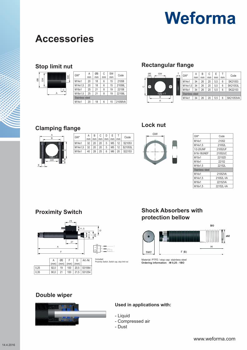
M14x1 20 18 6 15 21058M14x1,5 20 18 6 15 21058LM16x1 25 21 8 19 22158M16x1,5 25 21 8 19 22158LStainless steelM14x1 20 18 6 15 21058VA
SW
GWØB
CA
GW* Amm
Bmm
Cmm
Dmm
Emm
Tmm Ciode
M14x1 32 20 20 5 M5 12 S21053M14x1,5 32 20 20 5 M5 12 S21053LM16x1 40 28 25 6 M6 20 S22153
E
GW
BA
DC
ØE GW T
BA
C
GW* Amm
Bmm
Cmm
Emm
Tmm Code
M14x1 34 26 20 5,5 6 SK21053M14x1,5 34 26 20 5,5 6 SK21053LM16x1 34 26 20 5,5 6 SK22153Stainless steelM14x1 34 26 20 5,5 6 SK21053VA
GW* CodeM14x1 21052M14x1,5 21052L1/2-20UNF 21052UF9/16-18UNEF 21052UCM15x1 22152DM16x1 22152M16x1,5 22152LStainless steelM14x1 21052VAM14x1,5 21052L-VAM16x1 22152VAM16x1,5 22152L-VA
+
-
1
4
3
NO
PNP
M
A (mm)
ØE (mm)
F (mm)
G (mm)
Art.-Nr. IncludedProximity Switch, Switch cap, stop limit nut
27
Ø11
,5
ØE
G
11,5
25
A
F
0,25 92,0 19 100 20,5 S310640,35 90,0 21 100 21,5 S31254
GW
Material: PTFE / stop cap: stainless steelOrdering information: -M 0,25 - 1BO
Proximity Switch Shock Absorbers with protection bellow
Tiefe = T
Tiefe = T
Accessories
Stop limit nut
Clamping flange
Rectangular flange
Lock nut
Used in applications with:
- Liquid- Compressed air- Dust
Double wiper

www.weforma.com14.4.2016
GW* Amm
Bmm
Cmm
ø Dmm
ø Emm
SWmm Code
0,25 M 14 x 1 32 10 6 8 18 15 S210190,25L M 14 x 1,5 32 10 6 8 18 15 S21019L0,35 M 16 x 1 33 10 5 8 20 17 S221190,35L M 16 x 1,5 33 10 5 8 20 17 S22119L
ØD SW
B
A
C
ØE
ØD SW
B
A
C
ØE
F
G
GW
Hub HB
GW* Amm
Bmm
Cmm
ø Dmm
ø Emm
Fmm
Gmm
SWmm Code
0,25 M14x1 32 8 8 8 18 4 20 16 S21019-AK20,25 M 14 x 1,5 32 8 8 8 18 4 20 16 S21019L-AK20,35 M16x1 32 8 8 8 20 4 18 19 S22119-AK2
ØD SW
B
A
C
ØE
ØD SW
B
A
C
ØE
F
G
GW
Hub HB
GW* A A 1 B C ø D ø E L SW SW 1
mm mm mm mm mm mm mm mm mm
WEB-M 0,25 M 14 x 1,0 100,0 105,0 78,0 2,5 4 10 5 13 17
WEB-M 0,25L M 14 x 1,5 100,0 105,0 78,0 2,5 4 10 5 13 17
Stroke Energy absorptionEffective mass
Return spring force Torque Weight-0 (very soft) -1 (soft) -2 (medium) -3 (hard) -4 (very hard)
mm Nm/HB (max.) Nm/h (max.) min.-max.kg min.-max.kg min.-max.kg min.-max.kg min.-max.kg min. N max. N Nm max. kg
WEB-M 0,25 14 24 52800 - 1,6 - 1600 - - - 13 23 20 0,055
B
A
F
C
ØD
ØE
L
SW1
K
SW1HB
1) AK 1 AK 2
2) WEB-M 0,25 - 0,35
Solutions for Side Forces
BENEFITS
DIMENSIONS
PERFORMANCE
Designed for side forces upto15° without additionalmounting parts;included steel stop cap

www.weforma.com14.4.2016
Installation
Stroke
Flange
Installation with flange
Installation with Lock nut
Installation with stop limit nut
Stroke
Lock nut
Lock nut
Through hole Stroke
Stop limit nut

www.weforma.com14.4.2016
Adjustment:The damping factor is adjusted with the adjusting screw at the back-sided end of the shock absorber.The damping depends from the impact speed and the effective mass.Set possibilities on the scale 0-8
0 = low damping
8 = high damping
Adjustment: It is not allowed to adjust the shock absorber in operation conditions or during the opera-tion.In order to adjust the shock absorber set the adjustment screw to „6“ if the velocity is <1,3 m/s or to „4“ if the velocity is >1,3 m/s.Internal damage to the shock absorber can occur, if not adjusted in gradual increments. Do not drive in the final position under full load. If the damping is not sufficient, increase continously by rotating the adjustment to the next higher number. Maximum damping is achieved, when the highest number on the scale is reached.If the mass impacts exessively hard on the shock absorber (stop cap) the damping should be reduced by rotation of the adjustment to the next smaller number. Minimum damping is at „0“ setting.Secure the adjustment with the threaded pin. A hexagonal key is supplied for this purpose

www.weforma.com14.4.2016
FundamentalsShock absorbers may under no circumstances be:
-painted -welded -held with clamps -used on pull*
(exception: clevis mounting)
In hazardous environments (dirt, humidity, oil) shock absorbers must be protected against damage and failure with the necessary accessory. If several shock absorbers are used on the same application, the deceleration has to be distributed equally. The “Torque” (PERFORMANCE) indicates the maximum force by using the flats. The Weforma catalogue shows technical data with both minimum and maximum values. If a product is to be used in continuous operation and within a range of 20% from the minimum and maximum values shown, then written confirmation of suitability of use from Weforma is necessary.
Safety InstructionsBefore installation, commissioning, servicing and repair the data sheet is to be noticed. This work may only be performed by trained, introduced staff.
Electric connections according to the suitable national regulation. For Germany: VDE regulation VD E0100
Before all repair and servicing works the energy supplies (main switch, etc.) have to be switched off! Moreover, measures are necessary to prevent an unintential reconnect. For example, a warning sign “service works“ or “maintenance work“, applied to the switch.
Designated use
Check before installation and make sure the type name on the shock absorber or on the packaging is corresponding with delivery note. Industrial shock absorbers are maintenance-free and ready for installation.
• Temperature influence: at higher temperatures the shock absorber characteristic will change.• Movable loads have to be protected during the installation and maintenance against unintentional processes.• In operation outside the allowed temperature range, the shock absorber can lose his function. Due to heat radiation
don’t paint the shock absorber.• Fluids, gases and a dirty environment can affect or destroy the sealing system of the shock absorber. The result could
be a failure malfunction. Piston rod and sealing system has to be protected against fluids, gases and a dirty environ-ment.
• Damages at the piston rod can destroy the sealing system. Don’t grease or oil the piston rod.• Avoid traction forces on the piston rod to present internal damages.• The shock absorber can be pulled out of the construction during the impact.The construction needs to be able to resist
the max counterforce. Sufficient security must be calculated. The maximum counterforces performed in the calculation program can vary from the really appearing counter forces, because these are based on theoretical values.

www.weforma.com14.4.2016
Integrated end-stopUp to the WE-M 0,25 - 0,35 Mega-Line series the shock absorbers are provided with an integrated end-stop. If the integrated end-stop is used the remaining energy before end of stroke must not be higher than 10% of the total energy. For all models which are used as an emergency stop an external fixed stop is necessary.
Installation situation
The installation situation is any, however always in such a way that the complete shock absorber stroke can be used. The shock absorbers must be mounted like that the forces in centerinke about the piston rod are initiated. The maximum angle out of centre amounts to 3 °. With a bigger angle out of centre an AK1 / AK2 (see ``solutions for side forces´´) must be used or the shock absorber serie: WEB
Liability
Due to the number of possible uses of our products and the conditions of use that lie outside of our scope of influence, we accept no liability as to whether the purchase object is suitable for the Client‘s intended purpose. The verification to this effect, in particular the verification as to whether the purcha-se object is suitable for the planned use, is the responsibility of the Client alone, unless expressly agreed otherwise in writing.
For the reasons we accept no liability for the suitability of the purchase object for the purpose intended by the Client, except in cases of intent or gross negligence.
With damages, the not designated use and from high-handed, in these instructions do not originate to intended interventions, any guarantee and liability claim goes out towards the manufacturer.
Guarantee
By non-use of the original spare parts the guarantee claim goes out.
Environment protection
By the exchange from damaged parts is to be respected to a proper disposal.
Important information