Embed Size (px)
Citation preview

Maple Leaf Cement Factory Internship Report
Submitted by
Shoaib Hassan Khan
National University of Sciences & Technology

MLCF Internship Report
1
Preface Learning in practical side is somewhat that cannot be compared with books knowledge.
Moreover from engineering point of view learning experience matters a lot aside a
bachelor degree from a reputable institute.
The purpose of this report is to elaborate my experience and learning during my three
month internship period. In this three month I had visited every department and
analyzed different process involved in cement production. My main object was to view
the processes from Mechanical point of view i.e. Mechanical equipment, maintenance
work involve and troubleshooting of different problem faced in every department. In this
report I have tried my best to write everything I haves seen or learned during my three
month experience at Maple Leaf Cement. Process description and equipment involved
in every process is discussed in this report. Moreover step by step processes with
concise mass flow are also discussed in this report. In Maple Leaf Cement there are two
lines working in parallel, Line I capacity was 3800 TPD while line II capacity was 6700
TPD. Mostly data discussed in this report is of line II since it is newly developed and
efficient W.R.T to other lines. I hope that this report will cover a comprehensive view of
cement manufacturing plant from Mechanical point of view.
Shoaib Hassan Khan

MLCF Internship Report
2
Acknowledgement Thanking Almighty Allah, who bestowed me the knowledge and the courage to write this
report. This internship provided me a golden opportunity to learn. In this report I have
tried to relate everything that I thought was necessary. Though, it’s a bit difficult to say
anything about the perfection of the effort that I have made but I hope that it finds its
place somewhere to meet the required and expected criterion. I would like to add a few
deepest words for the people who were part of this report in numerous ways… people
who gave unending support right from the stage the report was assigned. Particularly I
wish to thank the foreman’s of every Area who helped me to gain a lot of Practical
Experience regarding the company and cement industry and also thankful to Mr.Zeshan
( A.M. Crushing Area) who have through his professional demeanour made me able to
to learn & Mr.Khalid who provide me an opportunity to learn and understand the working
of organization as an internee. I am also thankful to Mr Amir (Senior Manager Cement
mill) who played a role of polar star for me in the organization and whose experience
taught me a lot about the industry and the organization.
I am especially thankful to Mr. Jawed (Senior Manager Raw mill & kiln Area) who
helped me a lot in getting the knowledge of cement industry.
My special thanks to the person who from the first day of my internship help me
understand the manufacturing process,Mr. Fareed(A.M Design section),his gentle
,courteous and cooperative behaviour motivated me a lot.
And finally deepest and warmest appreciation to the whole team of Maple Leaf Cement
factory who helped me a lot in getting knowledge about the office working and about the
cement plant.
Shoaib Hassan Khan
MLCF Internship Report
3
Contents
Preface ............................................................................................................................ 0
Acknowledgement ........................................................................................................... 2
Introduction ..................................................................................................................... 7
About: .......................................................................................................................... 7
CEMENT: ................................................................................................................. 7
Legacy of the Leaf: ................................................................................................... 7
Vision: ...................................................................................................................... 8
Mission: .................................................................................................................... 8
Corporate Strategy: .................................................................................................. 8
Leading Edge Production Capabilities: ........................................................................ 8
Naturally Enriched: ...................................................................................................... 9
MLCF Basis for Uninterrupted Supply ...................................................................... 9
Core Values: ............................................................................................................ 9
Cross Functional: ................................................................................................... 10
Collective Wisdom: ................................................................................................. 10
Creative Thought Process: ..................................................................................... 10
Empathy: ................................................................................................................ 10
Integrity: ................................................................................................................. 10
Cement .......................................................................................................................... 11
What is cement? ........................................................................................................ 11
Types: ........................................................................................................................ 11
1-Common or General purpose cement: ................................................................ 11
2-Sulphate resistance cement: ............................................................................... 12
3-Rapid hardening cement: .................................................................................... 12
4. Low heat of hydration cement: ........................................................................... 12
5. Sulphate resistance: ........................................................................................... 12
Methods of cement manufacturing:............................................................................ 13
1- Wet process: ...................................................................................................... 13
2- Dry process: ....................................................................................................... 13

MLCF Internship Report
4
Wet process: .......................................................................................................... 13
Dry process: ........................................................................................................... 13
Wet process: .......................................................................................................... 13
Dry process: ........................................................................................................... 14
Grinding of the clinker: ........................................................................................... 14
Manufacturing layout ..................................................................................................... 15
General Process: ....................................................................................................... 15
Process Areas of LINE-II: .......................................................................................... 15
FLOW CHART OF THE MANUFACTURING PROCESS .......................................... 17
Plant Mass flow ............................................................................................................. 18
1-Line II Raw Meal Production: .................................................................................. 18
Lime stone: ............................................................................................................ 18
Clay: ....................................................................................................................... 18
Iron Ore: ................................................................................................................. 18
2-Raw Mill Feed: ........................................................................................................ 18
3-CF Silo: ................................................................................................................... 18
4-Clinker Production, Kiln: ......................................................................................... 19
5-Cement Mills: .......................................................................................................... 19
Process Description ...................................................................................................... 20
1. Raw Material Acquisition (Storage Area) ............................................................... 20
Major Equipment:....................................................................................................... 21
Crusher: ..................................................................................................................... 21
Stacker & Re claimer: ................................................................................................ 23
BS – Longitudinal ................................................................................................... 23
Bridge Scraper store: ............................................................................................. 23
Parts: ...................................................................................................................... 24
SS – Longitudinal ................................................................................................... 25
Side Scraper store: ................................................................................................ 25
Parts: ...................................................................................................................... 26
Belt Drive: .................................................................................................................. 27
2. Raw Mill (Raw mill Area): ....................................................................................... 28

MLCF Internship Report
5
How does a vertical mill work? ............................................................................... 29
Cyclone: ..................................................................................................................... 31
3. Pyro processing :( Kiln Area) ................................................................................. 32
Drying or preheating: ................................................................................................. 32
Burning (sintering): .................................................................................................... 32
Rotary Kiln Components & Parts: .............................................................................. 33
Kiln bearings and rollers: ........................................................................................... 33
Labeling: ................................................................................................................ 34
4. Clinker Cooling :( kiln Area) ................................................................................... 35
5. Clinker Storage: ..................................................................................................... 35
6. Finish Milling: ......................................................................................................... 36
Ball Mill: ..................................................................................................................... 36
Structure of Mill: ......................................................................................................... 37
Shell: ...................................................................................................................... 37
Thickness of the Mill Shell: ..................................................................................... 37
Shell Liners: ........................................................................................................... 37
OK Mill: ...................................................................................................................... 38
7. Packing and Loading ............................................................................................. 38
SOURCES OF POLLUTION ......................................................................................... 39
POLLUTANTS AND THEIR CONTROL .................................................................... 39
1. Air Pollutants ...................................................................................................... 39
a. Raw Material Acquisition .................................................................................... 39
b. Raw Milling ......................................................................................................... 40
c. Pyro processing .................................................................................................. 40
d. Clinker Cooling ................................................................................................... 41
e. Clinker Storage .................................................................................................. 41
f. Finish Milling ....................................................................................................... 42
g. Packing and Loading .......................................................................................... 42
Bag Filter: ............................................................................................................... 43
Power generation: ......................................................................................................... 44

MLCF Internship Report
6
List of Figures: Figure 1: Crusher working ............................................................................................. 21
Figure 2-Detailed labeled figure of Crusher ................................................................... 22
Figure 3-Limestone Stacker .......................................................................................... 23
Figure 4-Reclaimer ....................................................................................................... 24
Figure 5-Stacker and Reclaimer .................................................................................... 24
Figure 6-Working of Bridge reclaimer ............................................................................ 25
Figure 7-Figure referring parts of Bridge Reclaimer and Clay stacker .......................... 26
Figure 8-Belt drive Mechanical system .......................................................................... 27
Figure 9-Labeled Figure of Raw Mill(Left) and inside of Raw mill(Right) ....................... 28
Figure 10-WPU two stage mill gear unit with lubrication system ................................... 30
Figure 11-Three component of the drive system ........................................................... 30
Figure 12-Cyclone working ............................................................................................ 31
Figure 13-A pictorial view of pyro processing and kiln burning ...................................... 32
Figure 14-Mechanical construction of a rotary kiln ........................................................ 33
Figure 15-Roller Drive for Rotary Kiln............................................................................ 33
Figure 16-Roller Construction ....................................................................................... 34
Figure 17-A view of FL Smidth Cross bar cooler ........................................................... 35
Figure 18-Labeled Diagram of Ball Mill ......................................................................... 36
Figure 19-Working of Ball Mill ....................................................................................... 38
Figure 20-Ok Mill ........................................................................................................... 38
Figure 21-Working of bag filter ...................................................................................... 43

MLCF Internship Report
7
Chapter-1
Introduction
About: The Kohinoor Maple Leaf Group was born from the trifurcation of the Saigol group of
companies and is a reputable and leading manufacturer of textiles and cement. KMLG
comprises of Kohinoor Textile Mills limited (KTML) and Maple Leaf Cement factory
limited (MLCF). Both companies are incorporated in Pakistan and are listed on three
stock exchanges of the country.
CEMENT: Maple Leaf Cement is the third largest cement factory in Pakistan. It was set up in 1956
as a joint collaboration between the West Pakistan Industrial Development Corporation
and the government of Canada. It is strategically located at Daudkhel (District Mianwali)
in Northern Pakistan, which is an area rich in raw materials required for the production
of cement. Kohinoor acquired the ownership and management of Maple Leaf Cement
under the privatization policy of the government of Pakistan in 1992. At the time of
privatization in 1992, the capacity of Maple Leaf to produce Ordinary Portland Cement
(OPC) was 1000 tones per day (tpd). A second plant of 4000 tpd was commissioned in
1998 and a third plant of 6700 tpd came into production in 2006. It increased the total
capacity to 11,700 tpd. The capacity of White Cement has also increased from 100 tpd
to 500tpd with the addition of a new plant. This plant also has provisions for doubling
the capacity to 1000tpd. Presently Maple Leaf cement has 9% of the market share of
OPC and is a leading brand in Pakistan with a diverse customer base. It is also the
largest producer of White Cement in the country with 80% of market share. In order to
remain competitive in the market the management at Maple Leaf continuously
reevaluates its business strategies. With the increase of furnace oil prices the company
adopted coal as a more cost efficient and environmentally friendly fuel for kiln firing.
Legacy of the Leaf: The Green Maple Leaf has been an identity since 1960. The Leaf has traveled from
Canada and takes its green color from Pakistan.
It embodies a product that brings International standards engineered to transcend the
tough market conditions of Pakistan. Maple Leaf continues to live this legacy, even
decades after its birth. It continues to dominate the local and International markets,
wherever present.
The “Maple Leaf” was inherited from Canada and given a green color from Pakistan. It
symbolizes integrity, strength and a commitment towards building a prosperous future.

MLCF Internship Report
8
Vision: The Maple Leaf Cement Factory stated vision is to achieve and then remain as the most
progressive and profitable Company in Pakistan in terms of industry standards and
stakeholders interest.
Mission: The Company shall achieve its vision through a continuous process of having sourced
and implemented the best leading edge technology, industry best practice, and human
resource and by conducting its business professionally and efficiently with the
responsibility to all its stakeholders and community.
Corporate Strategy: At Maple Leaf Cement Factory manufacturing and marketing of different types of
consistently high quality cement, according to the demanding requirements of the
construction industry is done. The strategy of MLCF is to be competitive in the market
through quality and efficient operations. As a responsible member of the community,
MLCF is committed to serve the interest of their stakeholders and contribute towards
the prosperity of the Country.
Leading Edge Production Capabilities: Today with a production capacity of 12,000 tons/day,MLCF stand as the largest single
unit Cement Manufacturer in Pakistan. MLCF production plant is powered by cutting
edge technology that helps them dominate local & International markets.
Maple Leaf Cement has two separate plants for Grey and White Cement; each with
dedicated production lines within the same facility that ensure a continuous supply of
cement 24/7 – 330 days a year.
MLCF has kept itself abreast of global improvements in the cement manufacturing
technologies and processes. Staying true to our mantra of technological excellence,
Maple Leaf Cement underwent an expansion plan in 2007 to set up a state of the art
fuel efficient dry process plant based on the FLSmidth* technology. This facility has
allowed Maple Leaf to increase its production capacity to approximately 4 million tons
annually.
FLSmidth is a global engineering company based in Copenhagen, Denmark which is a
leading provider of one-source cement production plants worldwide and has a presence
in more than 40 countries.
Maple Leaf has a team of over 1,200 professionals and highly skilled workers that make
them what they are today.
MLCF Internship Report
9
Naturally Enriched:
MLCF Basis for Uninterrupted Supply
With a covered area of more than 3,000 acres, MLCF factory is situated at Daud Khel,
Punjab. Located near the Salt Range, it is surrounded by the finest quality of raw
materials; limestone, clay and sand. These valuable resources are quarried from the
mineral rich mountain ranges located at our manufacturing site. To ensure uninterrupted
supply, Maple Leaf Cement has strategically built separate production plants for Grey
and White Cement in this area.
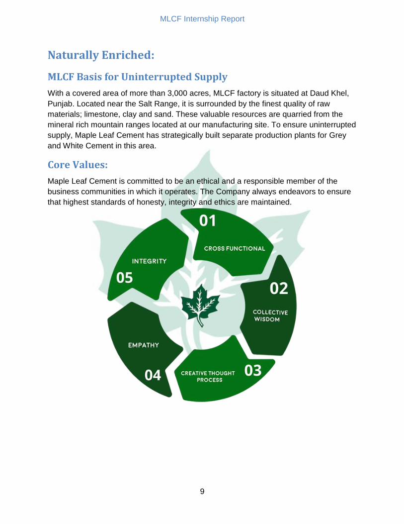
Core Values:
Maple Leaf Cement is committed to be an ethical and a responsible member of the
business communities in which it operates. The Company always endeavors to ensure
that highest standards of honesty, integrity and ethics are maintained.

MLCF Internship Report
10
Cross Functional: Cross functional teams often function as self-directed teams in order to achieve
common goals
Collective Wisdom: For sharing knowledge, innovative ideas, experience & individual expertise with others
to attain common objectives
Creative Thought Process: Out of the box ideas
Empathy: Ability to understand & share feelings of other. Put oneself in someone else’s shoes
Integrity: Adherence to moral & ethical principles; soundness of moral character & honesty.

MLCF Internship Report
11
Chapter-2
Cement
What is cement?
Cement is a material with adhesive and cohesive properties which make it capable of
bonding minerals fragments into a compact whole.
For constructional purposes, the meaning of the term "cement" is restricted to the
bonding materials used with stones, sand, bricks, building stones, etc.
The cements of interest in the making of concrete have the property of setting and
hardening under water by virtue of a chemical reaction with it and are, therefore, called
hydraulic cement.
The name "Portland cement" given originally due to the resemblance of the color and
quality of the hardened cement to Portland stone – Portland island in England.
The Basic Constituents of cement are Lime stone Clay Iron Ore Gypsum
First three constituents are mixed at early stage while gypsum is mixed at the later stage .These all basic constituents have their own role to play in cement manufacturing i.e. to give strength, to make it economical and making setting time optimum.
Types: In 1824 English man Joseph Aspdin, patented artificial cement made by the calcinations
of an argillaceous lime stone. He called it “Portland” because concrete made from it
resembles with a famous building stone obtained from land near England.
There are five types of Portland cements with variations of the first three according to
ASTM( AMERICAN SOCITY OF TESTING MATERIAL ) C150.
1-Common or General purpose cement: It is generally assumed unless another type is specified. It is commonly used for general construction especially when making precast and precast,pre stressed concrete that is not to be in contact with soils or ground water. The typical compound compositions of this type are:
55% (C3S), 19% (C2S), 10% (C3A), 7% (C4AF), 2.8% MgO, 2.9% (SO3), 1.0% Ignition
loss, and 1.0% free CaO. A limitation on the composition is that the (C3A) shall not
exceed fifteen percent.

MLCF Internship Report
12
2-Sulphate resistance cement: Type II is intended to have moderate sulfate resistance with or without moderate heat of
hydration. This type of cement costs about the same as Type I. Its typical compound
composition is:
51% (C3S), 24% (C2S), 6% (C3A), 11% (C4AF), 2.9% MgO, 2.5% (SO3), 0.8% Ignition
loss, and 1.0% free CaO.
A limitation on the composition is that the (C3A) shall not exceed eight percent which
reduces its vulnerability to sulfates
3-Rapid hardening cement: Type III is has relatively high early strength. Its typical compound .composition is:
57% (C3S), 19% (C2S), 10% (C3A), 7% (C4AF), 3.0% MgO, 3.1% (SO3),
0.9% Ignition loss, and 1.3% free CaO.
This cement is similar to Type I, but ground finer. Some manufacturers make a separate
clinker with higher C3S and/or C3A content, but this is increasingly rare, and the
general purpose clinker is usually used, ground to a specific surface typically 50-80%
higher. The gypsum level may also be increased a small amount.
4. Low heat of hydration cement: Type IV Portland cement is generally known for its low heat of hydration.Its typical
compound composition is:
28% (C3S), 49% (C2S), 4% (C3A), 12% (C4AF), 1.8% MgO, 1.9% (SO3), 0.9% Ignition
loss, and 0.8% free CaO.
The percentages of (C2S) and (C4AF) are relatively high and (C3S) and (C3A) are
relatively low. A limitation on this type is that the maximum percentage of (C3A) is
seven, and the maximum percentage of (C3S) is thirty-five.
5. Sulphate resistance:
Type V is used where sulfate resistance is important. Its typical compound.composition
is:
38% (C3S), 43% (C2S), 4% (C3A), 9% (C4AF), 1.9% MgO, 1.8% (SO3), 0.9% Ignition
loss, and 0.8% free CaO.
This cement has a very low (C3A) composition which accounts for its high sulfate
resistance. The maximum content of (C3A) allowed is five percent.

MLCF Internship Report
13
Methods of cement manufacturing:
1- Wet process: Grinding and mixing of the raw materials in the existence of water.
2- Dry process:
Grinding and mixing of the raw materials in their dry state.
The process to be chosen, depend on the nature of the used raw materials.
Wet process: the percentage of the moisture in the raw materials is high.
Dry process: The raw materials is so hard (solid) that they do not disintegrate by water
Cold countries, because the water might freeze in the mixture
Shortage of the water needed for mixing process.
Wet process: When chalk is used, it is finely broken up and dispersed in water in a washmill. The
clay is also broken up and mixed with water, usually in a similar washmill. The two mixtures are now pumped so as to mix in predetermined proportions and pass through a series of screens. The resulting – cement slurry – flows into storage tanks.
When limestone is used, it has to be blasted, then crushed, usually in two
progressively smaller crushers (initial and secondary crushers), and then fed into a ball mill with the clay dispersed in water. The resultant slurry is pumped into storage tanks. From here onwards, the process is the same regardless of the original nature of the raw materials. The slurry is a liquid of creamy consistency, with water content of between 35 and
50%, and only a small fraction of material – about 2% - larger than a 90 μm.
The slurry mix mechanically in the storage tanks, and the sedimentation of the
suspended solids being prevented by bubbling by compressed air pumped from bottom
of the tanks..
Finally, the slurry with the desired lime content passes into the rotary kiln. This is a
large, refractory-lined steel cylinder, up to 8 m in diameter, sometimes as long as 230
m, which is slightly inclined to the horizontal.
The slurry is fed in at the upper end while pulverized coal (oil or natural gas also might
be used as a fuel) is blown in by an air blast at the lower end of the kiln, where the
temperature reaches about 1450PoPC.
The slurry, in its movement down the kiln, encounters a progressively higher
temperature. At first, the water is driven off and COR2R is liberated; further on, the dry

MLCF Internship Report
14
material undergoes a series of chemical reactions until finally, in the hottest part of the
kiln, some 20 to 30% of the material becomes liquid, and lime, silica and alumina
recombine. The mass then fuses into balls, 3 to 25 mm in diameter, known as clinker.
The clinker drops into coolers.
Dry process: The raw materials are crushed and fed in the correct proportions into a grinding mill,
where they are dried and reduced in size to a fine powder. The dry powder, called raw
meal, is then pumped to a blending silo, and final adjustment is now made in the
proportions of the materials required for the manufacture of cement. To obtain a uniform
mixture, the raw meal is blended in the silo, usually by means of compressed air.
The blended meal is sieved and fed into a rotating dish called a granulator, water
weighing about 12% of the meal being added at the same time. In this manner, hard
pellets about 15 mm in diameter are formed.
The pellets are baked hard in a pre-heating grate by means of hot gases from the kiln.
The pellets then enter the kiln, and subsequence operations are the same as in the wet
process of manufacture.
Grinding of the clinker: The cool clinker (produced by wet or dry process), which is characteristically black and
hard, is inter ground with gypsum CaSOR4R.2HR2RO in order to prevent flash setting of the
cement, and to facilitate the grinding process. The grinding is done in a ball mill. The
cement discharged by the mill is passed through a separator, fine particles being
removed to the storage silo by an air current, while the coarser particles are passed
through the mill once again.

MLCF Internship Report
15
Chapter-03
Manufacturing layout
General Process: A general cement Manufacturing process consist of the following steps
Limestone Mining and Transportation to Crusher
Raw material Grinding.
Blending of Raw Material.
Storage of raw meal
Coal Grinding and Fine coal Handling.
Pre-heating in the six stage of Precalcinator string.
Pyro processing and calcination in the six Stage Pre-heater followed by
Clinkerisation in the Kiln.
Clinker cooler and storage.
Cement Grinding
Packing
In modern Cement manufacturing plant power generation is also done by effectively
using the hot gases of cooler. Since MLCF Line II is newly developed by FL Smidth and
FL Smidth is a big name in cement equipment manufacturing. So by installing Heat
exchanger at different points power generation was done effectively which will be
discussed at the later stages.
Process Areas of LINE-II: Limestone crusher(111)
Limestone Transport(121)
Clay Transport(122)
Limestone storage(131)
Limestone transport from storage(141)
Clay Transport from storage(143)
Additive Intake(142)
Gypsum intake and Transport(212,242)
Coal Transport to coal storage(211)
Coal mill feed to silo(231)
Raw coal transport to mill(241)
Raw mill feed(311)
Raw mill (321)
Exhaust gas conditioning(331)

MLCF Internship Report
16
Cf silo & kiln feed(341,351)
Preheater(421)
Kiln(431)
Clinker cooler(441)
Coal mill(461)
Clinker transport to storage(471)
Clinker storage and transport(481)
Cement mill feed I(511)
Cement mill feed II(512)
Cement mill I(531)
Cement mill II(532)
Cement transport I(541)
Cement Transport II(542)
Cement silo I(611)
Cement silo II (612)
Packing Plant(641-646)

MLCF Internship Report
17
FLOW CHART OF THE MANUFACTURING PROCESS

MLCF Internship Report
18
Chapter-04
Plant Mass flow
1-Line II Raw Meal Production:
Lime stone: Most abundant element of cement Limestone is handled wheel loaders and brought to
the crushing point. Now on average the capacity of EV crusher is 1000 TPH but it can
yield maximum 1200 TPH.Now this mass is conveyed through conveyor belts to the
limestone storage area, which has the capacity to store 35000 Tones i.e. 1.5 tone/m3
From Storage lime stone is transported to the weigh feeder.Limestoene can be
transported at the rate of 750-900 tph while the bin has the capacity of 500 t ,a volume
of 330 m3.From bin it can be provided at the rate of 60-600 tph as much it is needed.
Clay: Roller crusher provide clay on average rate of 280 TPH while it can provide at max 400
TPH.Clay storage has the capacity of 13000 tones i.e. 1.3 tone/m3.From storage clay
can be transported to the weigh feeder at the rate of 16 to 160 TPH while the bin has
the mac the max capacity of 195 tones. From weigh feeder it can be transported at the
rate of 20-200 TPH.
Iron Ore: Iron ore by wheel handler can be provided at the rate of 225-270 TPH according to
need since it is needed in fewer amounts. The feeder of iron has capacity of 625 tones.
From weigh feeder ore is provided at the rate of 2.5-25 TPH.
2-Raw Mill Feed:
Raw meal a proportionate mixture of limestone, iron ore and clay is added to the raw
mill at the rate of 540 tph with maximum capacity of 650tph while after adding reject
material it go up to 775tph.while the output of raw mill is 540tph to 650tph with
maximum capacity of 706tph.lime stone, clay and iron ore are present in the raw mill
feed mixture as 74%,24% and 2% respectively .
3-CF Silo: CF Silo also called as control flow silo has the capacity of 25500t with volume of 17500
m3.It can provide the material at a control rate of 115tph to 554tph while providing the
material at average rate of 462 to 554 tph.

MLCF Internship Report
19
4-Clinker Production, Kiln:
Raw meal passes through 2 strings, 5 stage preheater where coal is mixed through
precalciner at the rate of 14/23tph.from preheater it enters into the kiln which can
produce clinker at the rate of 6700 t/d. Kiln is 66m long and have diameter of 5.50 m.in
Kiln coal is added at the rate of 14/19tph.After kiln clinker passes through cooler cooler
is having SF4X7F and can cooler clinker at the rate 271/406 t/h. Now clinker can either
be stored in silo or existing off stand silo. Clinker silo has diameter of 50m and height of
26 m.
5-Cement Mills:
There are two cement mills present at MLCF one is Ok Mill one is ball Mill. Both mills
can handle the clinker and gypsum mixture at the rate of 175/210tph.while gypsum is
added t the clinker at the rate of 100.120tph.so the output of cement from both mills are
350/420 tph.Where it is stored in cement silos. There are two cement silos with
individual capacity of 21000t.From cement silos it can ne transported with equal
capacity of 200.240 tph to six packers with total 600 tph dispatch capacity.
MLCF Internship Report
20
Chapter-05
Process Description Cement industries typically produce Portland cement, although they also produce
masonry cement (which is also manufactured at Portland cement plants). Portland
cement is a fine, typically gray powder comprised of di calcium silicate, tri calcium
silicate, tri calcium aluminate, and tetra calcium alumino ferrite, with the addition of
forms of calcium sulfate. Different types of Portland cements are created based on the
use and chemical and physical properties desired. Portland cement types I - V are the
most common. Portland cement plants can operate continuously for long time periods
(i.e., 6 months) with minimal shut down time for maintenance.
The air pollution problems related to the production, handling, and transportation of
Portland cement are caused by the very fine particles in the product.
Procurement of raw materials
Raw Milling - preparation of raw materials for the pyro processing system
Pyro processing raw materials to form Portland cement clinker
Cooling of Portland cement clinker
Storage of Portland cement clinker
Finish Milling
Packing and loading
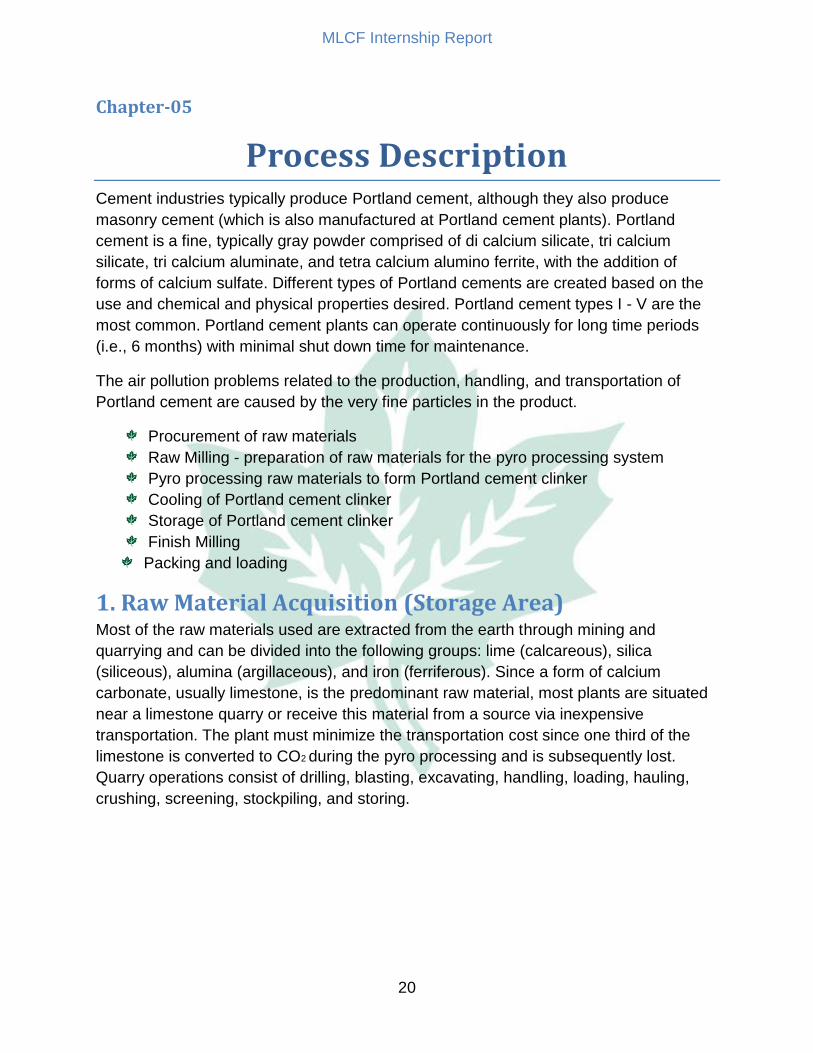
1. Raw Material Acquisition (Storage Area) Most of the raw materials used are extracted from the earth through mining and
quarrying and can be divided into the following groups: lime (calcareous), silica
(siliceous), alumina (argillaceous), and iron (ferriferous). Since a form of calcium
carbonate, usually limestone, is the predominant raw material, most plants are situated
near a limestone quarry or receive this material from a source via inexpensive
transportation. The plant must minimize the transportation cost since one third of the
limestone is converted to CO2 during the pyro processing and is subsequently lost.
Quarry operations consist of drilling, blasting, excavating, handling, loading, hauling,
crushing, screening, stockpiling, and storing.

MLCF Internship Report
21
Major Equipment: Major equipment of storage area include
Crushers
Belt conveyer with drives
Bag filters
Stacker
Bridge re claimer
Crusher:
Figure 1: Crusher working

MLCF Internship Report
22
Figure 2-Detailed labeled figure of Crusher

MLCF Internship Report
23
Stacker & Re claimer: BS – Longitudinal
Bridge Scraper store: The longitudinal Bridge Scraper store, type BS, operates with two piles. One pile is
stacked while the other is being reclaimed.A capacity of each pile covering 3½ to
7 days requirements are normally recommended for cement production. The material
entering the store on a rubber belt conveyor is discharged from the jib of the stacker
traveling on rails alongside the store at a preset speed. The height above the crest of
the pile is kept at a minimum to reduce dust emission. Reclaiming takes place from the
face of a pile at the natural angle of material slide. The bridge runs on rails on either
side of the stockpile. On the bridge is mounted a raking harrow system whose sweeping
movements cause the material to slide to the pile base. To loosen sticky and non-free
flowing materials active live-harrows are available. A scraper chain system conveys the
material to the outgoing belt conveyor. Skew running is automatically compensated for.
The system merely requires an operator when shunting from one pile to another.
Figure 3-Limestone Stacker

MLCF Internship Report
24
Parts: 1. Incoming belt conveyor
2. Jib
3. Conveyor belt on jib
4. Jib counterweight
5. Luffing unit
6. Operator cabin
7. Stacker bogie
8. Re claimer bogie
9. Hydraulic tensioning
unit
10. Scraper chain
11. Raking harrow
12. Raking car Figure 4-Reclaimer
13. Operator cabin
14. Outgoing belt conveyor
Figure 5-Stacker and Reclaimer

MLCF Internship Report
25
SS – Longitudinal
Side Scraper store: The longitudinal Side Scraper store, type SS, is used in a production line as a relatively
small bulk material buffer store. The store operates with stockpiles placed in line. While
building up one pile by Cone Shell or Chevron stacking another pile is reclaimed. The
material enters the store on a rubber belt conveyor along one side of the store. It is
discharged onto a stacker jib which is kept close to the pile crest to reduce dust
emission. Alternatively, stacking can take place by a tripper car supported by a frame
structure above the pile. The stacker and the side scraper travel on separate rails along
the store.The side scraper reclaims the material by means of a scraper chain system
which removes one slice at a time from the pile. The scraper chain fitted with blades or
buckets conveys the materials to the discharge point above the outgoing conveyor. The
system only requires an operator when shunting from one pile to another.
Figure 6-Working of Bridge reclaimer

MLCF Internship Report
26
Parts:
1. Hoist for raising 2. lowering chain
3. Operator cabin
4. Outgoing belt conveyor
5. Re claimer bogie
6. Scraper chain
7. Jib
8. Belt conveyor on jib
9. Stacker bogie
10. Operator cabin
11. Incoming belt conveyor
12. Hydraulic cylinder
13. Jib counterweight
Figure 7-Figure referring parts of Bridge Reclaimer and Clay stacker

MLCF Internship Report
27
Belt Drive: The types of conveyors used in cement industry are,
Belt conveyors
Roller conveyors
Cable conveyors
Pipeline conveyors
Screw conveyors
Elevating conveyors
Figure 8-Belt drive Mechanical system

MLCF Internship Report
28
2. Raw Mill (Raw mill Area): Raw milling involves mixing the extracted raw materials to obtain the correct chemical
configuration, and grinding them to achieve the proper particle-size to ensure optimal
fuel efficiency in the cement kiln and strength in the final concrete product.
Three types of processes may be used:
The dry process
The wet process
Semidry process
If the dry process is used, the raw materials are dried using impact dryers, drum dryers,
paddle-equipped rapid dryers, air separators, or autogenous mills, before grinding, or in
the grinding process itself. In the wet process, water is added during grinding. In the
semidry process the materials are formed into pellets with the addition of water in a
pelletizing device.
Figure 9-Labeled Figure of Raw Mill(Left) and inside of Raw mill(Right)

MLCF Internship Report
29
How does a vertical mill work? The raw materials are fed directly to the center of the grinding plate, which, thanks to
centrifugal forces and the pushing effect of the incoming materials themselves (both
fresh and separator coarse material), are distributed evenly under the grinding rollers.
The turning speed of the grinding plate, together with the pressure of the grinding rollers
creates the necessary friction for grinding the materials. After being ground the material
is transported to the dynamic separator by the (more or less hot) gas flow, where the
selection of the material takes place.
The gas flow, besides transporting the material, performs other important tasks:
First material selection; the coarse particles tend to fall back on the grinding plate
Thermal exchange; more efficient compared to tubular ball mills,
Thanks to the complete mix of gases and materials. The coarse material coming from
the separator is directed back to the centre of the grinding plate in order to be ground
again. The grinding process starts with the preparation of the so- called bed, where the
coarse material is crushed. Then the material is compressed and grounded by the
grinding rollers. The material, which flows over the damn ring is caught by the vertical
gas flow from the nozzle ring and lifted up. Coarse particles fall back to the grinding
table and Finer ones are swept up to the separator for being classified. The internal
circulation Rate depends mainly on the grind ability of the ground material and can
amount up to 15 to 25 cycles. Reducing the gas speed in the nozzle ring adjustment of
the open Area leads ti falling through of larger particles. The fall through material has to
be extracted with scrapers and mechanically re circulated to the mill feed
Separation
The use of modern separators in roller mills is state of the art. A sharp separation
improves the raw meal quality and avoids over grinding (saving of energy). Coarse
Tailings, fed through the tailings cone to the center of the grinding table, helps the
Formation of a more stable grinding bed. The raw meal fineness is easily controlled by
the adjustment of the cage rotor speed.

MLCF Internship Report
30
MAAG Gear construction (line II):
Component of the drive system
Thrust bearing
Planetary stage
Bevel stage
Figure 10-WPU two stage mill gear unit with lubrication system
Figure 11-Three component of the drive system

MLCF Internship Report
31
Cyclone: It is used mainly for separating material from air. After grinding from the raw mill a
mixture of hot gases and material passes through the cyclone. Cyclone separates
material from the air.
Figure 12-Cyclone working

MLCF Internship Report
32
3. Pyro processing :( Kiln Area) In pyro processing, the raw mix is heated to produce portland cement clinkers. Clinkers
are hard, gray, spherical nodules with diameters ranging from 0.32 - 5.0 cm (1/8 - 2")
created from the chemical reactions between the raw materials. The pyroprocessing
system involves two steps:
Drying or preheating: Calcining (a heating process in which calcium oxide is
formed),
Burning (sintering): The pyro processing takes place in the burning/kiln
department. The raw mix is supplied to the system as a slurry (wet process), a powder
(dry process), or as moist pellets (semidry process). All systems use a rotary kiln and
contain the burning stage and all or part of the calcining stage. For the wet and dry
processes, all pyro processing operations take place in the rotary kiln, while drying and
preheating and some of the calcination are performed outside the kiln on moving grates
supplied with hot kiln gases.
Figure 13-A pictorial view of pyro processing and kiln burning
MLCF Internship Report
33
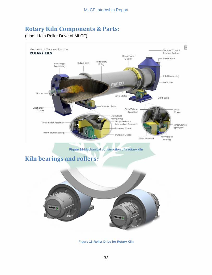
Rotary Kiln Components & Parts: (Line II Kiln Roller Drive of MLCF)
Figure 14-Mechanical construction of a rotary kiln
Kiln bearings and rollers:
Figure 15-Roller Drive for Rotary Kiln

MLCF Internship Report
34
The supports for rotary kilns are based on the two-roller support principle.
Each roller is seated in two sliding bearings, which are self-adjusting journal bearings.
The spherical ball socket of the bearings constantly ensures totally even axial and radial
contact between the bearing liner and the journal, even if one bearing is displaced
relative to the other, and when shaft deflection occurs.
Lubrication is based on the hydrodynamic lubrication principle, i.e. with formation of a
supporting film of oil between the bearing liner and the journal during rotation.
Retrofitting bearings and rollers onto a non-Valmet kiln can in some cases be done
without replacing the baseplate and thereby avoid civil work. In some cases, changes in
refractory configuration or cooler type overloads the support and a larger support
(baseplate, bearings, rollers) will be required to sustain the load.
Figure 16-Roller Construction
Labeling: 1. Thrust ring
2. Oil distribution tray
3. Oil elevators
4. Shaft journal
5. Bearing liner
6. Oil level indication
7. Connection for water cooling
8. Spherical ball socket
9. Seal arrangement,
MLCF Internship Report
35
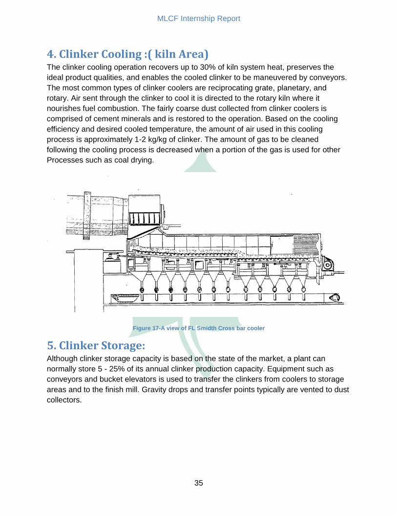
4. Clinker Cooling :( kiln Area) The clinker cooling operation recovers up to 30% of kiln system heat, preserves the
ideal product qualities, and enables the cooled clinker to be maneuvered by conveyors.
The most common types of clinker coolers are reciprocating grate, planetary, and
rotary. Air sent through the clinker to cool it is directed to the rotary kiln where it
nourishes fuel combustion. The fairly coarse dust collected from clinker coolers is
comprised of cement minerals and is restored to the operation. Based on the cooling
efficiency and desired cooled temperature, the amount of air used in this cooling
process is approximately 1-2 kg/kg of clinker. The amount of gas to be cleaned
following the cooling process is decreased when a portion of the gas is used for other
Processes such as coal drying.
Figure 17-A view of FL Smidth Cross bar cooler
5. Clinker Storage: Although clinker storage capacity is based on the state of the market, a plant can
normally store 5 - 25% of its annual clinker production capacity. Equipment such as
conveyors and bucket elevators is used to transfer the clinkers from coolers to storage
areas and to the finish mill. Gravity drops and transfer points typically are vented to dust
collectors.

MLCF Internship Report
36
6. Finish Milling: During the final stage of Portland cement production known as finish milling, the clinker
is ground with other materials (which impart special characteristics to the finished
product) into a fine powder. Up to 5% gypsum and/or natural anhydrite is added to
regulate the setting time of the cement. Other chemicals, such as those which regulate
flow ability or air entrainment, may also be added. Many plants use a roll crusher to
achieve a preliminary size reduction of the clinker and gypsum. These materials are
then sent through ball or tube mills (rotating, horizontal steel cylinders containing steel
alloy balls) which perform the remaining grinding. The grinding process occurs in a
closed system with an air separator that divides the cement particles according to size.
Material that has not been completely ground is sent through the system again.
Ball Mill: Ball or tube mills are rotating steel cylinders where size reduction of the mill feed is
Performed by motion of the grinding media. Rotation of the mill cylinder raises the pile
of mill feed and grinding media to an optimum high, necessary for grinding operation.
Grinding is performed by impact and friction between the grinding balls which hit one
against another, as well as between the grinding media and the mill lining itself. The
difference between ball mill and tube mill is the ratio of the tube length to the tube
diameter. Tube mills have a ratio of length to diameter of [3-6 : 1], for ball mill this
relation is[<2 : 1]. Two different processes occur inside the mill:
Crushing: Breaking up of the incoming particles from a size of about 30 mm to a
size of minus 2.5 mm diameter. This process takes place in the first
compartment of the mill.
Refining: Powdering of the particles until they reach the required fineness. This
process stakes place in the second or last compartment of the mill. Figure 18-Labeled Diagram of Ball Mill

MLCF Internship Report
37
Structure of Mill: Shell: The shell is welded structure and manufactured from steel sheets, or from fine-grained
Structure steel. Boiler plates are also frequently in use.
Thickness of the Mill Shell: The thickness of the mill shell ranges between 1/100 and 1/75 of the mill diameter. It
should be mentioned that the shell thickness depends not only the diameter, but also on
the length of the mill cylinder. Besides, the shell thickness of long mills are graded, i.e.
the shell thickness increase from both ends toward the mill center. When calculating the
thickness of the mill shell, it should be considered that the bolt holes for the mill liners
reduce the strength of the shell by about 11%.
Shell Liners: Clinker grinding is performed in two different stages: in the first stage where material
must be crushed, sufficient impacts are required to reduce coarser particles in to finer
ones, whereas in the second stage, an action of attrition should be take place. The first
compartment shell lining must assure an efficient lifting effect of grinding media charge
so that the grinding media give impacts strong enough to break large particles.
However, it shouldn't lift the grinding balls too high, since a part of them would then fall
on liners where no materials are found; this would accelerate the wear of liners and
media and cause a loss of energy. The first compartment ball charge must exerts a
maximum amount of impacts on the materials to be ground, and these impacts should
be strong enough to quickly reduce the clinker particle size. It is not advisable to use a
segregation lining in the first compartment. Segregation liners which allow an automatic
segregation of the grinding bodies are equipped in the second compartment more
recently. Large balls are directed towards the inlet end, with the ball dimension
decreasing regularly from the inlet towards the outlet where smaller balls are located.

MLCF Internship Report
38
Figure 19-Working of Ball Mill
OK Mill: Ok mill mostly work as the raw mill, which has been discussed before. The difference is
it has four rollers while the raw mill was having three rollers.
Figure 20-Ok Mill
7. Packing and Loading Once the production of Portland cement is complete, the finished product is transferred
using bucket elevators and conveyors to large, storage silos in the shipping department.
Most of the Portland cement is transported in bulk by railway, truck, or barge, or in 50 kg
(100 pound) multiwall paper bags. Bags are used primarily to package masonry cement.
Once the cement leaves the plant, distribution terminals are sometimes used as an
intermediary holding location prior to customer distribution. The same types of conveyor
systems used at the plant are used to load cement at distribution terminals.

MLCF Internship Report
39
Chapter-06
SOURCES OF POLLUTION Although Portland cement plants generate the same final product using similar
processes, plant layouts vary according to fuels and raw materials used location,
climate, site topography, and the manufacturer of the equipment.
POLLUTANTS AND THEIR CONTROL This section briefly discusses the nature of the pollutants generated from, and controls
used at,several sources in the cement manufacturing process. Air pollutants are
typically of greater concern than solid or liquid wastes.
1. Air Pollutants Air pollutants generated during the cement manufacturing process consist primarily of
particulates from the raw and finished materials, and fuel combustion by-products.
Controlling particulate emissions from sources other than the kiln usually entails
capturing the dust using a hood or other partial enclosure and transporting it through a
series of ducts to the collectors. The type of dust collector used is based on factors such
as particle size, dust loading, flow rate, moisture content, and gas temperature. The
best disposal method for collected dust is to send it through the kiln creating the clinker.
Additional air pollutants emitted include such materials as sulfur oxides and nitrogen
oxides generated from the kiln and drying processes. Sulfur dioxide is generated from
the sulfur compounds in the ores and the combusted fuel and varies in amount
produced from plant to plant. The efficiency of particulate control devices is inconclusive
as the result of variables such as feed sulfur content, temperature, moisture, and feed
chemical composition, in addition to alkali and sulfur content of the raw materials and
fuel. The combustion of fuel in rotary cement kilns generates nitrogen oxides from the
nitrogen in the fuel and incoming combustion air. The amount emitted depends on
several factors including fuel type, nitrogen content, and combustion temperature. Both
sulfur dioxide and some of the nitrogen oxide react with the alkaline cement and are
removed from the gas stream.
a. Raw Material Acquisition During raw material acquisition the primary air pollutant emitted is particulate matter.
Particulate matter is also emitted from the handling, loading, unloading, and transport of
raw materials, such as coal, purchased from another source. In certain areas, exhaust
from portable equipment may also be a consideration.

MLCF Internship Report
40
The following methods are used to control particulate emissions generated from the
quarry and handling of purchased raw materials:
fabric filters (pulse-jet or reverse-air/shaker)
equipment enclosures
water sprays (with and without surfactants)
enclosures
silos (with and without exhaust venting to
wind screens fabric filters)
foams
mechanical collectors
bins
chemical dust suppressants
paving
material storage buildings
Dust that is collected by these means is restored to the process. For quarry operations,
newer plants typically use the pulse-jet fabric filters while older plants employ the
reverse-air or shaker-type fabric filters.
b. Raw Milling Fugitive dust is emitted from raw material feeders, stackers, blenders, reclaimers,
conveyor belt transfer points, and bucket elevators used for transferring materials to the
mill department from storage. Particulate emissions from the dry raw mills and
subsequent equipment occur during temporary failure or from improperly designed or
maintained seals. The following devices are used to collect particulate matter in the raw
mill and raw mix storage areas:
mechanical cyclones (usually used in series with another control)
fabric filters (pulse jet or reverse air/shaker)
electrostatic precipitators (rarely used)
Newer plants typically use the pulse-jet fabric filters while older plants employ the
reverse-air or shaker type fabric filters.
c. Pyro processing The main pyro processing system emissions are nitrogen, carbon dioxide, water,
oxygen, nitrogen oxides, sulfur oxides, carbon monoxide, and hydrocarbons. Cement
kiln dust (CKD) is also produced. The cement kiln itself has been designated as best
available control technology (BACT) for the control of SO2. The highly alkaline
conditions of the kiln system enable it to capture up to 95% of the possible SO2
emissions. However, if sulfide sulfur (pyrites) is present in the kiln feed, this absorption

MLCF Internship Report
41
rate can decline to as low as 50%. Therefore, sulfur emissions can be decreased
through careful selection of raw materials.
No device to control cement kiln NOx emissions has been developed, but there are
several prospects:
stable kiln operation (reduces long term NOx emissions);
burner configurations for the rotary kiln (efficiency varies);
staged combustion for precalciner kilns;
recirculation of the flue gas (oxygen deficient air in the rotary kiln); and
alternative/low-nitrogen fuels.
Cement kiln dust (CKD) is the powder retrieved from the exiting gases and is either all
or partly returned to the operation or removed entirely. The type of system, the chemical
makeup of the raw materials and fuel, and the condition of the system operations all
affect the chemical configuration of the CKD. Portland cement specifications usually
limit the amounts of sodium and potassium. Because bypass CKD contains a large
quantity of these minerals, CKD is usually removed from the process. The CKD from a
preheater tower is composed of the same general elements as the kiln feed and
therefore is returned to the process. The handling, storage, and deposition of CKD can
generate fugitive dust emissions.The following methods are used to control particulate
emissions from the kiln system:
reverse-air fabric filters
electrostatic precipitators (ESPs)
acoustic horns (sometimes used in conjunction with the two devices above)
d. Clinker Cooling Reciprocating grate clinker coolers most often employ fabric filters, but ESPs and gravel
bed filters are also used with a mechanical cyclone or multiclone dust collector
sometimes placed infront. Newer plants typically use pulse-jet or pulsed-plenum fabric
filters and older plants use reverse-air type fabric filters which may simply be a smaller
form of a kiln fabric filter. Gravel bed filters, which are also used by the cement industry,
contain quartz granules; contaminated gas passes through this filter and the dust settles
to the bottom of the bed.
e. Clinker Storage The devices used to control dust emissions from clinker storage areas are similar to
those used in the raw milling process. The particulate emissions generated by dropping
clinkers onto storage piles can be reduced by using a rock ladder or variable-height,
automatic, stacker belt conveyor systems. Fugitive dust generated from open storage
piles is tempered by rain and snow, wind breaks, and pile covers. Clinker in open piles
is moved using front-end loaders; in storage halls overhead bucket cranes are used.

MLCF Internship Report
42
Fugitive clinker dust emitted from open storage piles is common and very difficult to
control.
f. Finish Milling Particulate matter is emitted from mill vents, air separator vents, and material-handling
system vents. Newer plants usually use pulse-jet or pulsed-plenum fabric filters with
high-efficiency separators, while older plants use reverse-air/shaker fabric filters. The
cement dust collected by the fabric filter is restored to the system. In cold weather, a
plume may develop at the baghouse vent; this may be mistaken for particulate matter,
but actually is condensed water vapor from the cooling system.
g. Packing and Loading In the shipping department particulate matter is emitted from the silos and the handling
and loading operations. Active and passive fabric filters are used to collect this dust.
During loading of the product, particulate emissions are controlled by a fabric filter
connected to the transport vessel; collected dust is restored to the shipment. To ensure
dust-free loading onto the transport vessel, a flexible loading spout consisting of
concentric tubes is used. The outermost tube seals the delivery spout to the transport
vehicle. The product is then delivered through the inner tube and displaced air drawn up
the outer tube to a filter. At distribution terminals, fabric filters are again used and the
collected dust is returned to the product. New plants typically use pulse-jet fabric filters
while older plants use reverse-air or shaker-type fabric filters.

MLCF Internship Report
43
Figure 21-Working of bag filter
Bag Filter:

MLCF Internship Report
44
Chapter-07
Power generation: MLCF produces its own electricity by effectively recovering the heat utilized in the pyro
processing.
Heat is created at two points
At Pre-Calciner
In the kiln
There are two heat exchangers present at the line II.
One is connected with the pre heater that utilized the gases of pre heater and kiln
Second is present at the cooler side
Steam created is effectively transported to power plant where impulse and reaction
turbines are installed and about 15 megawatts electricity is produced.so MLCF only
need a small amount to meet its power need.
More over steam is also produced from the exhaust of second power plant where diesl
engines are installed.