Embed Size (px)
Citation preview

Copy © October, 2002 by Kinetic Systems, Inc. All rights reserved.
1
Section I As you Begin: Congratulations! The VIBRAPLANE Model 9100/9200 Vibration Isolation Table you have purchased has been designed by Kinetic Systems, Inc. For many years of trouble-free user service. It will deliver superior vibration isolation performance for a broad range of research, quality assurance, and production applications. The VIBRAPLANE Model 9100/9200 Vibration Isolation Systems is a four legs active Air Suspension System. The maximum gross load capacity for the VIBRAPLANE Model 9211 and 9101 are 700 lbs, 800 and 1,300 lbs respectively at 80 PSI. If the VIBRAPLANE 9100/9200 Table is to be operated at less than maximum gross load capacity, a proportionately lower pressure air source may be used. For example, a 30 to 50 PSI air source is generally adequate for most small instruments. In order to get full benefit from your VIBRAPLANE Model 9100/9200 Table, we suggest you follow the easy, step-by-step instructions in this manual. Technical Assistance: Need Technical Assistance? First, refer to the “Troubleshooting” Section of this Manual. If your problem persists, the technical support staff at Kinetic Systems, Inc. will be glad to answer any questions. Just telephone us at (617) 522-8700, or FAX (617) 522-6323 or Email kineticsystems.com. Damage due to shipping: When you’ re VIBRAPLANE 9100/9200 Table Arrives, inspect it carefully for any damage due to shipping. If ANY DAMAGE IS DETECTED, NOTIFY THE SHIPPING CARRIER IMMEDIATELY. SAVE ALL PACKING MATERIALS.

Copy © October, 2002 by Kinetic Systems, Inc. All rights reserved.
2
Section I I Set Up Procedure: The following equipment’s and tools are recommended to set up your 9100/9200 Series Vibration Isolation System:
• Hydraulic lifting device • Carpenter’s level • Screwdriver • Adjustable wrench
Refer to Fig. 1 for outline drawings of Labmate I and II Workstation. All 9211
and 9100/9200 Series Vibration Isolation Table is completely assembled and tested at the factory, except for optional items such as Guardrails, Casters, Monitor Supports, Sliding Shelf (9101, and 9102 only), and Fixed Shelf Prior to shipment.
Fig. 1 9101/9102 and 9211 Ser ies Vibration Isolation Workstation.

Copy © October, 2002 by Kinetic Systems, Inc. All rights reserved.
3
Isolation Leg Stand: 1. Carefully remove all shipping material (metal strapping, cardboard, etc.). Additional
parts such as optional Guardrails, Casters, Monitor Supports and Sliding Shelf have been packed separately inside the shipping container. Set these parts aside for later installation.
2. Remove the protective wood blocks from the bottom of each leg. The Mechanical
Leveling Feet are fully retracted for shipping. Rotate each foot CLOCKWISE (SEE Fig. 2) so that they extend ¾” below bottom of the leg.
3. Carefully remove the legstand to final location. If the back of the table is to be
positioned against the wall, be sure to leave enough access space to permit attachment of the rear optional Guardrail(s).
4. Place Tabletop on top of the legstand on four rubber bumpers (one in each corner). 5. The Tabletop weights several hundred pounds, so use of a hydraulic lifting device is
recommended for its installation. Place the Tabletop on four rubber bumpers. Center the Tabletop left-to-right and front-to-back. Proper positioning of the Tabletop is important for even distribution of weight on the legs and to avoid rubbing against the optional Guardrails.
Fig. 2 Mechanical Leveling Foot Height Adjustment
6. Place a carpenter’s level diagonally across the Tabletop and check for level condition (both directions) at its final location by raising or lowering the Mechanical Leveling Feet (as shown in Fig. 2).

Copy © October, 2002 by Kinetic Systems, Inc. All rights reserved.
4
7. If an out-of-level condition is detected, adjust the Leveling Feet by inserting a thin rod or screwdriver (as shown in Fig. 2) into the hole on the side of the Leveling Foot. Rotate COUNTERCLOCKWISE to shorten leg and lower the Tabletop. Rotate CLOCKWISE to lengthen leg and raise Tabletop. After you have leveled the tabletop all four legs should be in contact with the bottom surface of the tabletop, if any gap is observed rotate the leveling foot clockwise to close the gap.
8. Your 9100/9200 Series Vibration Isolation Workstation is now ready for operation.

Copy © October, 2002 by Kinetic Systems, Inc. All rights reserved.
5
Section I I I Operation and Set Up Procedure for Optional items:
Fig 3a 9101/9102 Air line Schematic
Fig. 3b 9211 Air line Schematic

Copy © October, 2002 by Kinetic Systems, Inc. All rights reserved.
6
The following instructions explain how to pressurized air supply. 1. Using the Umbilical Assembly (1/8”Odx10ft. polyurethane tubing and ¼” NPT
fitting), connect the pressurized air supply to the inlet of the Filter Regulator (as shown in Fig. 3a and 3b). The polyurethane tubing may be shortened by cutting with a razor blade. If additional pipe fittings are required to complete the connection at the pressurized air supply, these must be supplied by the user.
2. The pressurized air supply should be clean dry air or nitrogen from a regulated line or
bottle, with pressure not to exceed 100psi. 3. Position your equipment on the Tabletop, centering it as much as possible. 4. The air inlet Filter Regulator is described in the attached (see page 20). 5. Turn on the air supply and adjust the Filter Regulator on the Control Panel clockwise
for approximately 80 psi. it is advised not to exceed 80 psi supply pressure (as shown on Fig. 4).
Fig. 4 9100/9200 Ser ies Control Panel I llustration.
6. Be sure the Valve Adjustment Screw on each VIBRA-LEVEL Valve Arm is touching
the bottom surface of the Tabletop, and that each Valve Arm is slightly below horizontal for in the fill position and 10 degree above horizontal after floating for neutral position.
7. The Tabletop should begin to “ float” within 5 to 10 minutes. IF floating does not
occur at one or more legs, check the inlet pressure on Filter Regulator and rise if necessary or turn the Valve Adjustment Screw(s) COUNTERCLOCKWISE.

Copy © October, 2002 by Kinetic Systems, Inc. All rights reserved.
7
Fig. 5 The VIBRA-LEVEL Valve Adjustment.
8. When the Tabletop is completely “ floating” , adjust each Valve Adjustment Screw so that the Tabletop is floating approximately ¼ of an inch (as shown Fig. 5). The tabletop should be level at this point since leveling was done prior to this by raising and lowering of the Mechanical leveling Feet.
9. Tighten the Lock Nut on each of the Valve Adjustment screws. 10. Once the tabletop with your equipment is “ floating” , read the system Gage and set the
Regulator so that the inlet pressure is approximately 10-15 psi greater than the Gage reading. For example: If the Reference Pressure Gage reads 55 psi, adjust the Filter Regulator Gage to read 65 to 70 psi.
11. I f more loads are added to the Tabletop, you may increase the inlet pressure by an
amount large enough to maintain the 10-15 psi difference between the inlet pressure and the Gage reading. It is advised not to exceed 80 psi Filter Regulator Pressure.
12. Once the tabletop has been leveled this condition will be automatically maintained as
long as the supply pressure is sufficient. If the air supply is shut off for a period of time and then turned back on the tabletop will automatically return to the preset level.

Copy © October, 2002 by Kinetic Systems, Inc. All rights reserved.
8
13. If it is desired to lock out the Isolation Systems for a short period of time, this can be accomplished by lowering the tabletop onto rubber bumper. The system is lowered by reducing the Filter Regulator pressure to slightly below the system pressure reading. System will automatically bleed down and rest onto rubber bumper, this will maintain most of the compressed air volume in the isolators and thereby reduce the “ fill time”, when repressurizing.
CAUTION: Never remove heavy loads from the Tabletop suddenly. Two options are recommended for removal of heavy loads: (1) remove heavy loads gradually to permit controlled pressure reduction in the legs by the VIBR-LEVEL Servo Valves or (2) reduce the pressure in the Filter Regulator gage to below what is required to support the tabletop.

Copy © October, 2002 by Kinetic Systems, Inc. All rights reserved.
9
Guardrail Adjustment:
Fig. 6 9100/9200 Guardrail Height Adjustment.
1. The Guardrails on the 9100/9200 Series Isolation Table were designed to allow the
operator to vary the height to accommodate for different tabletop thickness. Optional Sliding Shelves may be retrofitted. There are four fixed locations on the Guardrail Support Bar that allow the operator to find the right location for him/her.
2. To adjust the Guardrail height, loosen the Adjustment Knob on both sides of the
Guardrail and raise or lower the Guardrail evenly (as shown in Fig. 6). It is not necessary for the front and rear Guardrails to be at the same height, except when used with an optional Sliding Shelf, with a Sliding Shelf, the Guardrail must be adjust to allow a minimum of ¼ inch clearance between the bottom surface of the Shelf and the Top surface of the tabletop (as shown in Fig. 7).

Copy © October, 2002 by Kinetic Systems, Inc. All rights reserved.
10
Optional Sliding Shelf (9100 only):
Fig. 7 Sliding Shelf I llustration
1. The optional Sliding Shelf can be ordered in different widths to provide the operator
with enough surface area needed for equipment not isolated. 2. The Guardrail height must be adjusted as previously discussed to allow for the Shelf
or Shelves. 3. The Sliding Shelf or shelves simply drop onto the front and back guardrails (as shown
Fig. 7). They can then be slide into any position desired. Optional Padded Armrest: 1. The optional adjustable padded Armrest is ordered in pairs.
Fig. 8 Adjustable Padded Arm Rest I llustration. 2. To install the adjustable padded arm rests simply drop onto the guardrail (as shown
Fig. 8). They can then be slide into any position desired.
Copy © October, 2002 by Kinetic Systems, Inc. All rights reserved.
11
Optional Fixed Shelf:
Fig. 9 Optional Fixed Shelf Assembly.
Unpack and place the Fixed Shelf on the bottom Leg Stand brace (Refer to Fig. 9). For 9100 only. 1. Adjust support bolt by raise or lower to contact with the floor surface. 2. Tight down the nut with support bolt adjustment. For 9211 only 1. Position clearance hole on Fixed Shelf over tapped hole in Side Brace of Leg Stand. 2. Bolt Fixed Shelf in place using ¼-20 flat head screw and Finish Washer provided.

Copy © October, 2002 by Kinetic Systems, Inc. All rights reserved.
12
Optional Monitor Support: The following instructions explain how to install the optional Monitor Support assembly (Refer to Fig. 10).
Fig. 10 Optional Monitor Suppor t.
1. Be sure your VIBRAPLANE Model 9101/9102 Table is SET UP as described in the
previous section of this Manual. 2. The Monitor Support is shipped in three sub assemblies: The Monitor Shelf
Assembly, the Swivel Support bar Assembly, and the Vertical Support Bar assembly. 3. Install Top and Bottom Spacer blocks in place by lining up the two holes of the two
spacer blocks with the ¼-20UNC hole on legstand secure into place using two ¼-20x.75” flat head screws for Top Spacer block and Bottom Spacer block.
Copy © October, 2002 by Kinetic Systems, Inc. All rights reserved.
13
4. Hold the Vertical Support Bar firmly in place, lining up the lower hole with the hole in the Top Spacer block. Bolt the Vertical Support Bar into place using the two 3/8 spring lock washers and two 3/8-16x2.50” hex head bolts provided.
5. Position the Swivel Support Bar on top of the Vertical Support Bar, and screw in
clockwise until the desired height is reached. 6. Screw the Monitor Shelf Assembly into the threaded portion of the Swivel Support
Bar until the desired height is reached. 7. Tighten both lock nuts to prevent unwanted movement. 8. Further adjustments of the monitor shelf can be made by rotating the Swivel Support
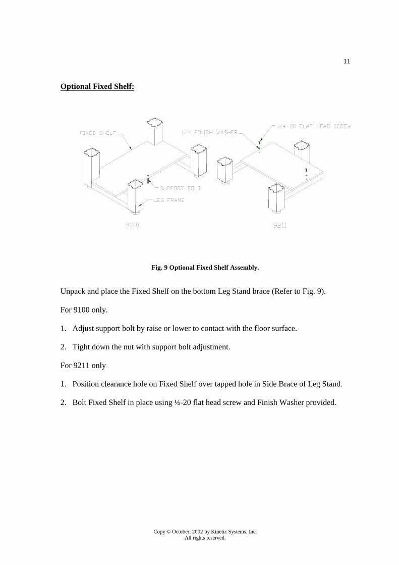
bar Assembly or the Monitor Support Assembly. Optional Rear and Side Equipment Shelf Assembly: The following instructions explain how to install the Optional Rear and Side Equipment Shelf Assembly (Refer to Fig. 11).
Fig. 11 Optional Rear and Side Equipment Shelf Assembly.

Copy © October, 2002 by Kinetic Systems, Inc. All rights reserved.
14
1. Be sure your VIBRAPLANE Model 9101/9202 Table is SET UP as described in the previous sections of this Manual.
2. Unpack the Support Posts, Shelf brackets, and the Shelf. 3. Attach the Support Posts on the Top and Bottom Spacers using the 3/8-16UNCx2.5”
long hex head bolts. (See Optional Monitor Support on page 12). 4. Position the Shelf Bracket in the slots on the Shelf Bracket Support to achieve the
desired height for the Shelf. 5. Place and center the shelf on the Shelf Brackets. 6. Secure the Shelf into place by screwing the #8x.50” long wood screws into the
bottom of the shelf from the underside of the Shelf Bracket. Optional Casters: 1. The Optional Caster supplied with the 9100/9200 Series Isolation Table are retrofit
table, which means that they could be supplies for 9100/9200 Series Isolation Tables already in field.
2. In order to set up the Casters first retract the Casters to their lowest possible positions. 3. Adjust the Mechanical Leveling Feet on the Table so that they extend down from the
leg tube by approximately 1 inch.
Fig. 12 Optional Caster Set Up and Use.
4. You are now ready to attach the Caster to the leg tube. The Caster can be attached to either of 2 sides on the leg tube.

Copy © October, 2002 by Kinetic Systems, Inc. All rights reserved.
15
5. Place the caster assembly onto the leg tube on 1 of the 2 sides best suited and slide the Caster assembly up, making sure the hook assemblies on the back of the caster assembly is on the inside of the leg tube.
6. Tighten the 2 nylon tipped, set screws on each Caster Assembly. These will hold the
Caster Assembly in place when they are not in use. 7. To remove the Caster Assembly reverses the previous procedures. 8. Engaging the Caster can be done by turning the bolt on top of the Caster Assembly
clockwise until the caster plate in horizontal or parallel with the floor. The leveling foot on that leg should rise, if more clearance is needed this can be done by raising the Leveling Foot into the leg tube.
9. Lower all four Casters and the System is ready to be removed. It is recommended to
have at least ¼ inch clearance between the Leveling Foot and the floor. 10. Once the system is in its desired location retract the Casters by reversing the previous
steps and reveled the System. It is not recommended to float the System while the Casters supporting the Systems.
Optional Faraday Enclosure:
The following instructions explain how to install the Faraday Enclosure to 9100/9200 Series Vibration Isolation table. Refer to the assembly drawing in Figure 14.
Required Materials:
• 2 side panel assemblies. • 2 door assemblies. • 1 top screen. • 1 rear screen. • 1 top, front connecting tube. • 1 bottom, top connecting tube. • 1 rear, bottom connecting tube. • 2 side rail assemblies. • 2 guard rail assemblies
Required Tools:
• Screwdriver. • Rubber mallet. • Carpenter’s level

Copy © October, 2002 by Kinetic Systems, Inc. All rights reserved.
16
Procedures:
1. All connections are made by matching the numbers.
2. Stand the two side assemblies on a flat surface.
3. Using a rubber mallet, hammer the front, rear tube onto the black corner connectors. (As show on Fig. 13).
Fig. 13 Faraday Enclosure installation
4. Drop the top screen into place and fasten from the bottom using #4X.25” sheet
metal screw provided (if the pre-drilled holes do not align, rotate the screen 180°).
5. Place the rear screen into position and secure from the outside using #4X.25” sheet metal screw (Again, if the pre-drill holes do not align, rotate the screen 180°).
6. Level your 9100 system by placing a bubble level diagonally across the guardrails
and adjusting the leveling feet until completely level.
7. Place the faraday enclosure onto the front and rear angel supports.
8. Fasten the faraday enclosure to the support angle from the bottom using #6X.38” sheet metal screw.
9. Attach the door assemblies to the front of faraday enclosure using the screws
provided, then close the doors and make sure the doors close properly.
10. If the doors hit when try to close them, the system is not leveled properly.

Copy © October, 2002 by Kinetic Systems, Inc. All rights reserved.
17
Fig. 14 Faraday Enclosure.

Copy © October, 2002 by Kinetic Systems, Inc. All rights reserved.
18
Optional hanging shelf:
1. Align 11GA. triangular shelf on top corner existing faraday enclosure prior to drill .12"dia holes (5 places) on faraday enclosure.
2. Secure triangular shelf to faraday enclosure using #10X.50 pan head sheet metal
screw provided.
3. Fasten the hanging posts to the bottom triangular using 1/4-20UNC X .75” flat head screw and finish washers.
4. Hold into place and attach the 7GA. triangular hanging Shelf using the
1/4-20UNC X .75 inch Flat Head Screws and Finish Washers.
Fig. 15 Optional hanging shelf.

Copy © October, 2002 by Kinetic Systems, Inc. All rights reserved.
19
Section IV Trouble Shooting: The purpose of this section is to aid the user in the diagnosis and repair of any minor problems that may occur. If your difficulty persists, call Kinetic Systems, Inc.’s technical support staff for assistance.
Symptom: Tabletop Will Not “ Float”
Possible Causes Probable Solutions
Valve Arms set incorrectly
Adjust Valve Arm
Supported load too heavy
Reduce load to system capacity
Supported load uneven
Redistribute load evenly
Gross air leak
Locate leak and repair
Air restriction in fitting or tubing
Find restricted fitting or Tube and replace
Symptom: Tabletop “ Float” but will not Isolate
Possible Causes
Probable Solutions
Rubbing between Tabletop and system structure
Reposition Tabletop
Foreign object between Tabletop and system structure
Remove foreign object
Wires or tubing too stiff. Use more flexible wire or large service loop
One piston too high Lower the piston by turning the Valve Arm Adjustment Screw CLOCKWISE.
One piston too low Raise the piston by turning the Valve Arm Adjustment Screw
COUNTERCLOCKWISE

Copy © October, 2002 by Kinetic Systems, Inc. All rights reserved.
20
Symptom: Tabletop Over Reactive
Possible Causes
Probable Solutions
Air pressure differential too high (i.e., more than 10-15 psi)
Reduce air pressure differential to 10-15 psi
Equipment on Tabletop has a high center of gravity
Reduce air pressure differential to 5 psi. If symptom persists, call Kinetic Systems,
Inc. VIBRA-LEVEL Servo Valve oscillating
Call Kinetic Systems, Inc. for replacement.
Section V Recommended Spare Parts: While maintenance requirements for the 9100/9200 Series Vibration Isolation Table are minimal, some parts can be damaged if the system is improperly moved. In order to avoid any inconvenience, Kinetic Systems, Inc. recommended that the user maintain one or two spare parts inventory of possible replacement items. These items are listed below:
MODEL NO.
REC. QUANTITY ON HAND
PART NO.
DESCRIPTION
9101,9102,9211
2
130200-05
Leveling Valve
9101 : 2 9101,9211, (Front)
9211 : 1
123168-03
Airmount (Isolator) (200#)
9101 : 2 9102,9211, (Rear)
9211 : 1
123169-03
Airmount (Isolator) (300#)

Copy © October, 2002 by Kinetic Systems, Inc. All rights reserved.
21
Section VI Replacement Isolator Installation: The following instructions explain how to replacement airmount (Isolator) for your 9100/9200 Series Vibraplane Optical Table. Required Materials:
• Replacement Isolator (as per specification)
• Silicone rubber (RTV 732 or Equivalent) Required Tools: • Long flat head Screwdriver.
Fig. 16 9101/9102 and 9211 Replacement Airmount.

Copy © October, 2002 by Kinetic Systems, Inc. All rights reserved.
22
Prior to replacing the airmount remove the tabletop and pressurize the system. Check the airmount and all fittings for leaks. If a fitting is leaking try stopping the leak by tighten the fitting. If the leak persists depressurize the system and replace the airmount as describe below. 1. Turn off air supply and exhaust air from damaged airmount. 2. Remove airmount by using the long flat head screwdriver by gently prying from all
sides of the airmount (as shown on Fig. 16.) (CAUTION: Do not damage the tubing coming into the leg tube).
3. Disconnect the airline (tubing) from the side of damaged airmount. 4. Clean any dry silicone from support plate airmount seat. 5. Reconnect the airline (tubing) to the new airmount assembly and apply four small
bead of silicone to bottom surface of the airmount shear pad. 6. Install new airmount assembly by pressing the airmount into support plate. Rotate the
airmount clockwise to remove any slack in the tubing so that the tubing will not come in contact with leg tube. (Do not pull tubing tight).
7. The Replacement airmount installation is now completed.

Copy © October, 2002 by Kinetic Systems, Inc. All rights reserved.
23
Section VI I Filter Regulator Installation and Operation: Installation: Installation vertical position so that air flow is in direction of arrow stamped on body of unit. Before piping-in, blow out line to remove scale and other foreign matter. If pipe compound is used, apply only to male threads and just enough to make tight joints. Reduced Pressure Adjustment: To unlock adjustment, pull knob up into forward most position. Turn knob clockwise to increase the reduced or regulated pressure and counter-clockwise to lower pressure. With relieving-type regulators, the reduced pressure follows adjustment of the screw, with non-relieving regulators adjustment for lower reduced pressure will not be obtained until the reduced pressure system is “bled-off” or until air flow starts (Refer to Fig. 17).
Fig. 17 Filter Regulator .
Maintenance: To obtain best efficiency and longest periods of trouble-free operation the air supply must be kept clean, as dirt is the most common cause of erratic regulator operation. Only a few parts require occasional replacement-most trouble can be cure and prevented by thorough and careful cleaning procedure. To clean, it is not necessary to remove unit from its piping or line. At the bottom of the bowl is a drain valve which should be periodically opened (turn clockwise) particularly when sediment is visible in bowl.

Copy © October, 2002 by Kinetic Systems, Inc. All rights reserved.
24
Disassembly for Cleaning: Use diagram on reverse as a guide to disassembly. Depressurized the air line, unscrew and remove the bowl. Unscrew the filter element retainer, and let down the vane plate, disc assembly and bottom spring. If the o-ring on the disc assembly appears worn or nicked, it should be replaced. Unscrew the spring cage and remove the diaphragm appears swollen or stiff, it should be replaced. Reassemble the unit in the same order, making sure the disc assembly stem fits into the small hole in the center of the diaphragm. Tighten the spring cage and bowl slightly more than hand tight (up to 50 inch pounds torque). Cleaning for best results clean parts with alcohol. After cleaning blow out parts including body of unit with compressed air. The filter cone should be blown out form the inside, plugging one end with finger. Plastic bowl must be cleaned with household soap only.

Copy © October, 2002 by Kinetic Systems, Inc. All rights reserved.
25
Appendix

Copy © October, 2002 by Kinetic Systems, Inc. All rights reserved.
26
Warranty
Equipment manufactured by Kinetic Systems, Inc. (KSI) is warranted against defective workmanship and materials for one (1) year from date of delivery. Defective material or items will be replaced at no charge. This warranty does not include labor to remove and install the material or item in question. Material returned under Warranty will not be accepted without the prior approval and assignment of a Return Authorization Number by KSI. All returns must be shipped Freight Prepaid unless KSI authorizes otherwise. In those instances where returns must be by Motor Freight (truck), KSI will furnish the proper commodity rate classification for lowest shipping cost.