Embed Size (px)
Citation preview

SHELL PROCESSING SUPPORT FORMAT
FOR 3D SURVEYS
AS ADOPTED BY THE SEG IN 1993 SEG TECHNICAL STANDARDS COMMITTEE
Rev 2.1 The revisions to this document allow this format to conform to the new SEGD Rev 2.1 SEG Field Tape Standards as revised Jan, 2006.
Shell Internationale Petroleum Maatschappij B.V., The Hague, The Netherlands
ii
SPS FORMAT CONTENTS INTRODUCTION ....................................................................................................................................................... 1
Controlling organization ...........................................................................................................................................2
FIELD SYSTEM ......................................................................................................................................................... 2
SHELL PROCESSING SUPPORT FORMAT FOR 3D SURVEYS.................................................................. 5
GENERAL................................................................................................................................................................ 5 Data record specification ................................................................................................................................... 5 Data record sorting order................................................................................................................................... 5 Format for survey data on 9-track tape ............................................................................................................. 5 Format for survey data on floppy disc ............................................................................................................... 6
HEADER RECORD SPECIFICATION................................................................................................................. 6 Instrument code (I) tables ................................................................................................................................... 7 Receiver code (Rx) tables.................................................................................................................................... 8 Source code (Sx) tables. ...................................................................................................................................... 8 Quality Control check records ........................................................................................................................... 9
POINT RECORD SPECIFICATION ................................................................................................................... 10 RELATION RECORD SPECIFICATION........................................................................................................... 11 COMMENT RECORD SPECIFICATION (OPTIONAL) ..................................................................................... 12 HEADER RECORD DESCRIPTION .................................................................................................................. 13
Seismic instrument header records .................................................................................................................. 16 Seismic receiver header records ...................................................................................................................... 17 Seismic source header records ......................................................................................................................... 18 Quality Control check records ......................................................................................................................... 19
POINT RECORD DESCRIPTION ....................................................................................................................... 20 RELATION RECORD DESCRIPTION .............................................................................................................. 23
APPENDIX 1 - EXAMPLE OF SPS FORMAT................................................................................................... 25
R FILE..................................................................................................................................................................... 25 S FILE ..................................................................................................................................................................... 28 X FILE .................................................................................................................................................................... 30
LIST OF FIGURES
FIGURE 1 FIELD ACQUISITION MANAGEMENT SYSTEM............................................................................................... 3 FIGURE 2 AUTOMATIC RECORDING ............................................................................................................................... 4 FIGURE 3 LAND ELEVATIONS ...................................................................................................................................... 21 FIGURE 4 TIDAL ELEVATIONS...................................................................................................................................... 22

1
INTRODUCTION The purpose of the format is to establish a common standard for the transfer of positioning and geophysical support data from 3D field crews to seismic processing centers. The format can also be used for other types of seismic surveys. With the growth and increased complexity of land 3D surveys there was a need to establish a robust and standard procedure for logging, during acquisition, the positioning and geophysical spread relation data in a way that reduces errors, allows the field crews to quality control the data, and hence detect and correct errors before the data was transferred to the seismic processing centers. Quality control was carried out as the first stage in the processing centers. Experience has shown that most errors are only detected when the geophysical and coordinate information are integrated, and that often spread relation errors could not be corrected, leading to the deletion of otherwise good quality records. Providing the processing centers with checked data in a standard format, containing all relevant field data significantly reduced the time spent by the processing centers on initial quality control and increased the quality of the end products. Comments on Revision 2.1 Recently, advances in acquisition technology and improvements in cost efficiencies have greatly increased the volume of data, in terms of channel counts, source/receiver densities, and surface area. This increase in the shear number of elements to account for has led to a situation where both the SEGD and the SPS formats can no longer adequately reflect the positioning and geophysical spread relation data. This was partially addressed in Revision 2.0 of the SEGD format, but was not reflected in an update to the SPS. To this end, this revision (2.1) to the SPS format has been undertaken in conjunction with Revision 2.1 of the SEGD format and has been named accordingly (in the absence of a revision 2.0 of the SPS). It is the intent of this revision to act as a stop gap measure to meet the immediate needs of the community. To that end, the original text and formats have been left unchanged unless a clear need has been seen to make changes. Modifications to the format itself have been limited to address the pressing needs of current acquisition, and to encompass the likewise limited changes made to the SEGD format in Revisions 2.0 and 2.1. Although it was agreed by the SEG Technical Standards Committee that future SEG standards would use and revisions where possible would be compatible with the EPSG Geodetic Database (now part of OGP) this minor revision will not include this standard. Adoption of the EPSG Geodetic Database compatibility has been left for the next major SEGD/SPS Rev 3 document release. Summary of Changes to the SPS Format for Revision 2.1 The following list discusses some of the specific changes of Revision 2.1.
1) Addition of a line sequence number which will allow more than one production line per tape to be recorded as long as a unique combination of field file number and line sequence number are used per storage unit. See pages 7,13.

2
2) Point Record Specification table values and descriptions were modified to accommodate updated formats, defaults, justification and min/max units in keeping with SEGD Revision 2.1. Some header records will be rendered redundant or obsolete with new format, ie; H31 Line number format. See page 7.
3) Relation Record Specification table value and descriptions were modified to accommodate larger field record numbers, value changes on from and to channel items and updating formats, default values, justification and columnar entries in keeping with SEGD Revision 2.1. See page 11.
4) Geodetic datum updated to reflect WGS84 vs WGS72. See page 14. 5) Reference to UKOOA P1/84 updated to UKOOA P1/90. See page 21. 6) Appendix 1- Example of SPS Format, R, S, and X files updated to reflect changes
to new Revision 2.1 format. See page 25-32.
Controlling Organization The SPS rev 2.1 is administered by the SEG Technical Standards Committee. Any questions, corrections or problems encountered in the format should be addressed to: Society of Exploration Geophysicists P.O. Box 702740 Tulsa, Ok 74170-2740 Attention: SEG Technical Standards Committee Phone: (918) 497-5500 Fax: (918) 497-5557 Internet site: www.seg.org
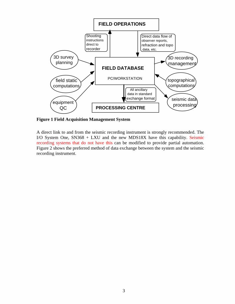
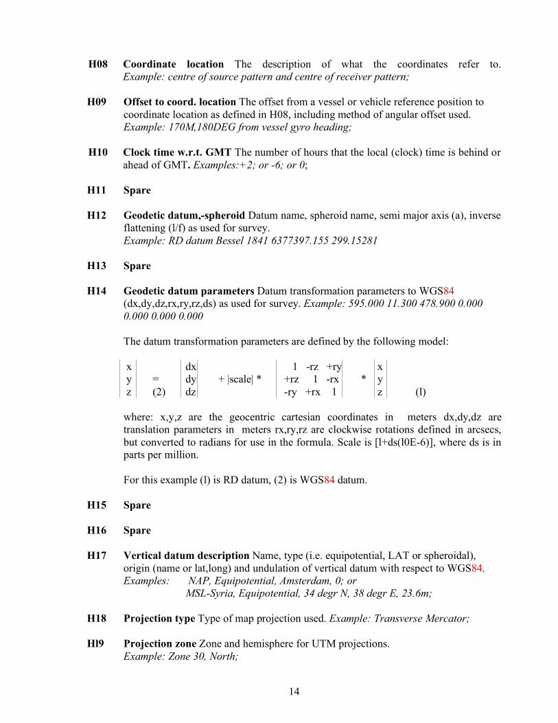
FIELD SYSTEM The field crews must have an acquisition management system to generate the SPS format during the survey. Errors will be reduced both during recording and during the generation of the SPS format if automated procedures are introduced at survey set-up and during daily recording. Figure 1 shows the main elements of such a system; The Field Database, Topographical computations and 3D recording management are the minimum elements required to support the generation of the SPS format.
3
FIELD OPERATIONS
FIELD DATABASE
PC/WORKSTATION
PROCESSING CENTRE
Shootinginstructionsdirect to recorder
3D recordingmanagement
topographical computations
seismic dataprocessing
field staticcomputations
equipment QC
3D survey planning
Direct data flow of observer reports, refraction and topo data, etc.
All ancillary data in standardexchange format
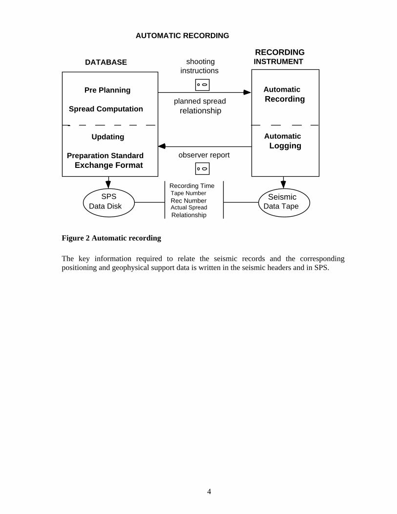
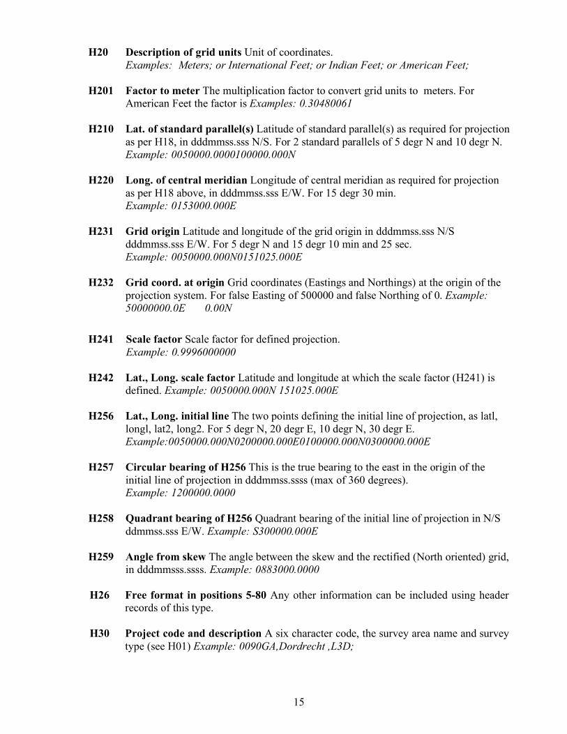
Figure 1 Field Acquisition Management System A direct link to and from the seismic recording instrument is strongly recommended. The I/O System One, SN368 + LXU and the new MDS18X have this capability. Seismic recording systems that do not have this can be modified to provide partial automation. Figure 2 shows the preferred method of data exchange between the system and the seismic recording instrument.
4
DATABASE
Pre Planning
Spread Computation
Updating
Preparation StandardExchange Format
RECORDING INSTRUMENT
Automatic Recording
Automatic Logging
shootinginstructions
planned spreadrelationship
observer report
Data Disk Seismic
Data Tape
Recording TimeTape Number Rec NumberActual Spread
Relationship
AUTOMATIC RECORDING
SPS
Figure 2 Automatic recording The key information required to relate the seismic records and the corresponding positioning and geophysical support data is written in the seismic headers and in SPS.
5
SHELL PROCESSING SUPPORT FORMAT FOR 3D SURVEYS Name: SPS format
GENERAL Coordinates and elevations of geophysical lines may be determined by interpolation between observed break points in the line. The point files contains coordinates and elevations of all geophysical points (observed and interpolated) and of all permanent markers. The shotpoint and relational files are to be sorted chronologically, and the receiver file is to be sorted in ascending sequence of line, point and point index numbers. In order to avoid ambiguities each physical position in the field (shotpoint or receiver group) must have a unique name.
Data record specification The data set consists of three files with an optional fourth comment file, each with an identical block of header records. For magnetic tapes each file is terminated by a record containing "EOF" in col. 1-3 First file : Receiver File. "Point Records" with details of receiver groups or permanent markers. Second File : Source File. "Point Records" with details of shotpoints (power source). Third File : Cross-Reference File "Relation Records" specifying for each shotpoint its record number and the relation between recording channel numbers and receiver groups Optional : Comment File. "Comments" with details of the observers report.
Data record sorting order Sort fields and sorting order. Receiver File : 'R' records. Line name, Point number, Point index Source File : 'S' records. Julian day and Time of recording shotpoint Cross-Reference File : 'X'records. Sorted in the same order as the Source File.
Legacy Format for survey data on 9-track tape Tape specifications and tape layout Half-inch magnetic tape : IBM compatible, non-label. Number of tracks : 9. Number of bytes per inch : 6250 (1600 is a permissible alternative). Mode : EBCDIC coded. Record length : 80 bytes. Block size : 1600 bytes (20 logical records). Physically separated by inter-record gap. An "EOF" statement followed by an IBM tape mark shall be written after the end of a file and a tape shall be closed by two IBM tape marks. In general, a tape may contain one or more files depending on the type of survey. Each file shall start with a number of 'Header Records' followed by 'Data Records' and closed by an EOF statement and an IBM tape mark.
6
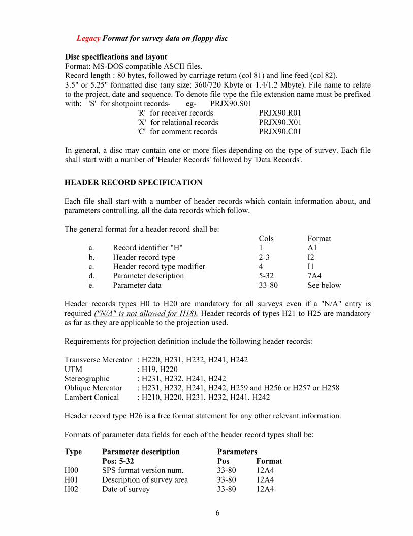
Legacy Format for survey data on floppy disc Disc specifications and layout Format: MS-DOS compatible ASCII files. Record length : 80 bytes, followed by carriage return (col 81) and line feed (col 82). 3.5" or 5.25" formatted disc (any size: 360/720 Kbyte or 1.4/1.2 Mbyte). File name to relate to the project, date and sequence. To denote file type the file extension name must be prefixed with: 'S' for shotpoint records- eg- PRJX90.S01 'R' for receiver records PRJX90.R01 'X' for relational records PRJX90.X01 'C' for comment records PRJX90.C01 In general, a disc may contain one or more files depending on the type of survey. Each file shall start with a number of 'Header Records' followed by 'Data Records'.
HEADER RECORD SPECIFICATION Each file shall start with a number of header records which contain information about, and parameters controlling, all the data records which follow. The general format for a header record shall be: Cols Format a. Record identifier "H" 1 A1 b. Header record type 2-3 I2 c. Header record type modifier 4 I1 d. Parameter description 5-32 7A4 e. Parameter data 33-80 See below Header records types H0 to H20 are mandatory for all surveys even if a "N/A" entry is required ("N/A" is not allowed for H18). Header records of types H21 to H25 are mandatory as far as they are applicable to the projection used. Requirements for projection definition include the following header records: Transverse Mercator : H220, H231, H232, H241, H242 UTM : H19, H220 Stereographic : H231, H232, H241, H242 Oblique Mercator : H231, H232, H241, H242, H259 and H256 or H257 or H258 Lambert Conical : H210, H220, H231, H232, H241, H242 Header record type H26 is a free format statement for any other relevant information. Formats of parameter data fields for each of the header record types shall be: Type Parameter description Parameters Pos: 5-32 Pos Format H00 SPS format version num. 33-80 12A4 H01 Description of survey area 33-80 12A4 H02 Date of survey 33-80 12A4
7
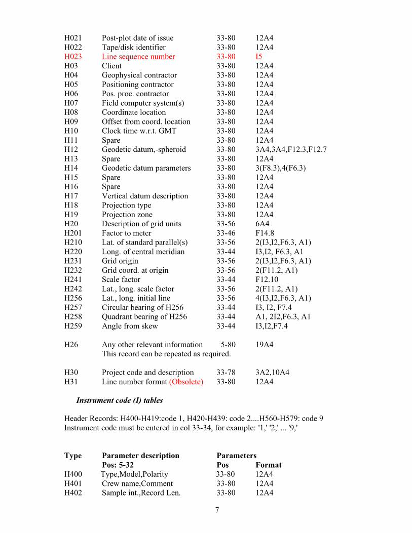
H021 Post-plot date of issue 33-80 12A4 H022 Tape/disk identifier 33-80 12A4 H023 Line sequence number 33-80 I5 H03 Client 33-80 12A4 H04 Geophysical contractor 33-80 12A4 H05 Positioning contractor 33-80 12A4 H06 Pos. proc. contractor 33-80 12A4 H07 Field computer system(s) 33-80 12A4 H08 Coordinate location 33-80 12A4 H09 Offset from coord. location 33-80 12A4 H10 Clock time w.r.t. GMT 33-80 12A4 H11 Spare 33-80 12A4 H12 Geodetic datum,-spheroid 33-80 3A4,3A4,F12.3,F12.7 H13 Spare 33-80 12A4 H14 Geodetic datum parameters 33-80 3(F8.3),4(F6.3) H15 Spare 33-80 12A4 H16 Spare 33-80 12A4 H17 Vertical datum description 33-80 12A4 H18 Projection type 33-80 12A4 H19 Projection zone 33-80 12A4 H20 Description of grid units 33-56 6A4 H201 Factor to meter 33-46 F14.8 H210 Lat. of standard parallel(s) 33-56 2(I3,I2,F6.3, A1) H220 Long. of central meridian 33-44 I3,I2, F6.3, A1 H231 Grid origin 33-56 2(I3,I2,F6.3, A1) H232 Grid coord. at origin 33-56 2(F11.2, A1) H241 Scale factor 33-44 F12.10 H242 Lat., long. scale factor 33-56 2(F11.2, A1) H256 Lat., long. initial line 33-56 4(I3,I2,F6.3, A1) H257 Circular bearing of H256 33-44 I3, I2, F7.4 H258 Quadrant bearing of H256 33-44 A1, 2I2,F6.3, A1 H259 Angle from skew 33-44 I3,I2,F7.4 H26 Any other relevant information 5-80 19A4 This record can be repeated as required. H30 Project code and description 33-78 3A2,10A4 H31 Line number format (Obsolete) 33-80 12A4
Instrument code (I) tables Header Records: H400-H419:code 1, H420-H439: code 2....H560-H579: code 9 Instrument code must be entered in col 33-34, for example: '1,' '2,' ... '9,' Type Parameter description Parameters Pos: 5-32 Pos Format H400 Type,Model,Polarity 33-80 12A4 H401 Crew name,Comment 33-80 12A4 H402 Sample int.,Record Len. 33-80 12A4
8
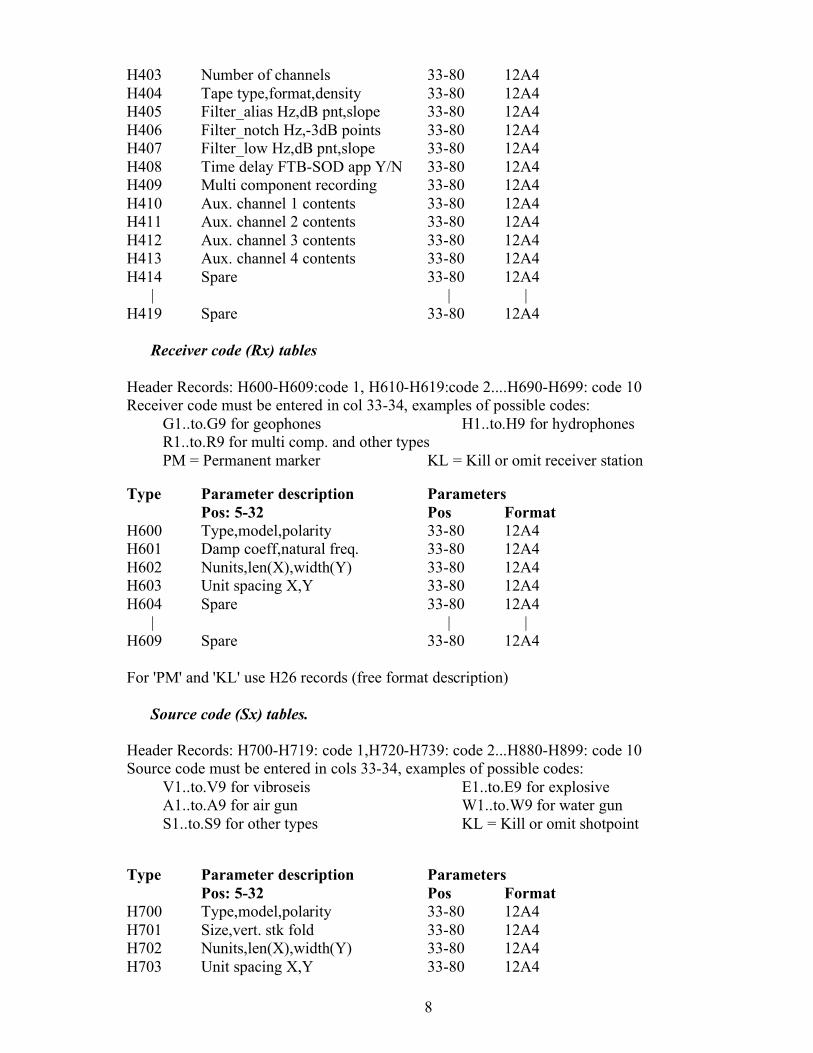
H403 Number of channels 33-80 12A4 H404 Tape type,format,density 33-80 12A4 H405 Filter_alias Hz,dB pnt,slope 33-80 12A4 H406 Filter_notch Hz,-3dB points 33-80 12A4 H407 Filter_low Hz,dB pnt,slope 33-80 12A4 H408 Time delay FTB-SOD app Y/N 33-80 12A4 H409 Multi component recording 33-80 12A4 H410 Aux. channel 1 contents 33-80 12A4 H411 Aux. channel 2 contents 33-80 12A4 H412 Aux. channel 3 contents 33-80 12A4 H413 Aux. channel 4 contents 33-80 12A4 H414 Spare 33-80 12A4 | | | H419 Spare 33-80 12A4
Receiver code (Rx) tables Header Records: H600-H609:code 1, H610-H619:code 2....H690-H699: code 10 Receiver code must be entered in col 33-34, examples of possible codes: G1..to.G9 for geophones H1..to.H9 for hydrophones R1..to.R9 for multi comp. and other types PM = Permanent marker KL = Kill or omit receiver station Type Parameter description Parameters Pos: 5-32 Pos Format H600 Type,model,polarity 33-80 12A4 H601 Damp coeff,natural freq. 33-80 12A4 H602 Nunits,len(X),width(Y) 33-80 12A4 H603 Unit spacing X,Y 33-80 12A4 H604 Spare 33-80 12A4 | | | H609 Spare 33-80 12A4 For 'PM' and 'KL' use H26 records (free format description)
Source code (Sx) tables. Header Records: H700-H719: code 1,H720-H739: code 2...H880-H899: code 10 Source code must be entered in cols 33-34, examples of possible codes: V1..to.V9 for vibroseis E1..to.E9 for explosive A1..to.A9 for air gun W1..to.W9 for water gun S1..to.S9 for other types KL = Kill or omit shotpoint Type Parameter description Parameters Pos: 5-32 Pos Format H700 Type,model,polarity 33-80 12A4 H701 Size,vert. stk fold 33-80 12A4 H702 Nunits,len(X),width(Y) 33-80 12A4 H703 Unit spacing X,Y 33-80 12A4
9
Following records are only required if source type= Vibroseis V1..V9 H704 Control type 33-80 12A4 H705 Correlator,noise supp 33-80 12A4 H706 Sweep type,length 33-80 12A4 H707 Sweep freq start,end 33-80 12A4 H708 Taper,length start,end 33-80 12A4 H709 Spare 33-80 12A4 H710 Spare 33-80 12A4 Following records are only required if source type= Explosive E1..E9 H711 Nom. shot depth,charge len. 33-80 12A4 H712 Nom. soil,drill method 33-80 12A4 H713 Weathering thickness 33-80 12A4 H714 Spare 33-80 12A4 H715 Spare 33-80 12A4 Following records are only required if source type = air gun A1..A9 or = water gun W1..W9 H716 P-P bar m,prim/bubble 33-80 12A4 H717 Air pressure psi 33-80 12A4 H718 No. sub arrays,Nom depth 33-80 12A4 H719 Spare 33-80 12A4
Quality Control check records Type Parameter description Parameters Pos: 5-32 Pos Format H990 R,S,X file quality control 33-60 2A4,I4,4A4 H991 Coord. status final/prov 33-68 4A4,I4,4A4
10
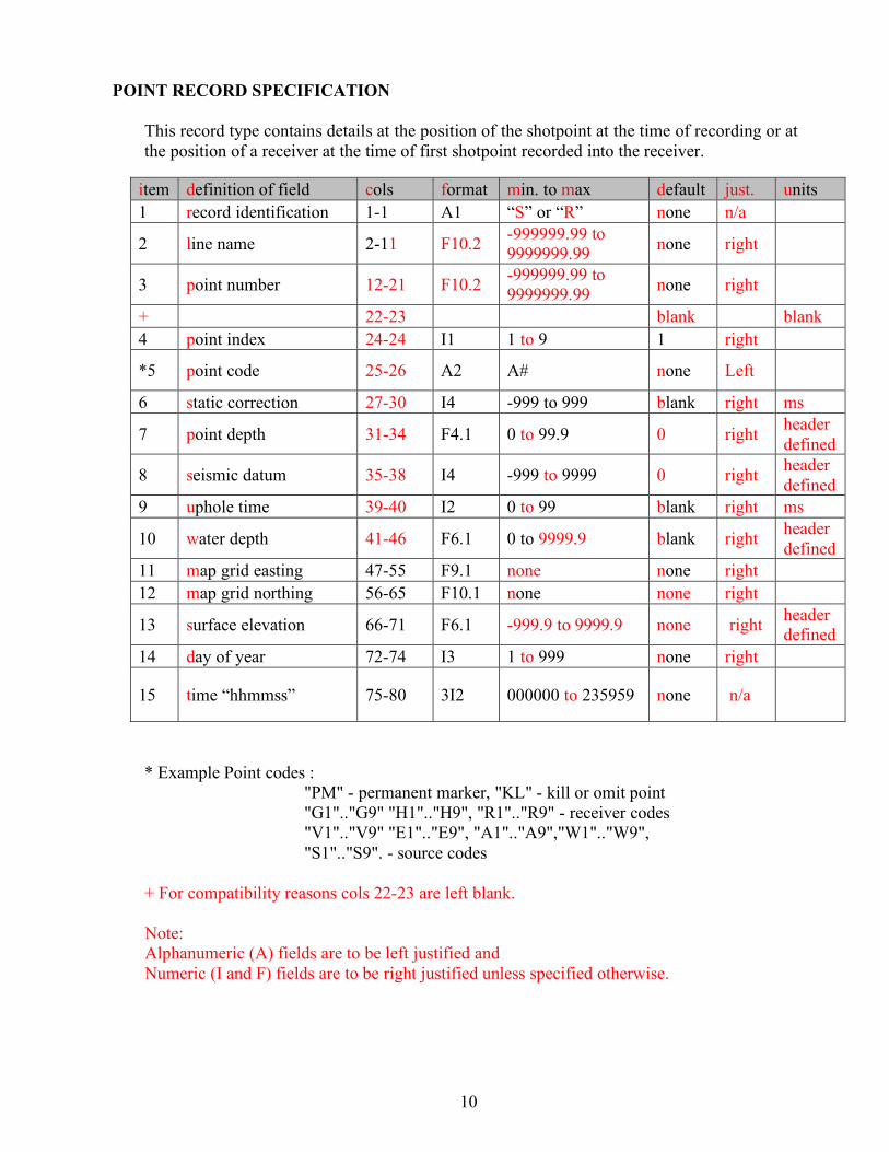
POINT RECORD SPECIFICATION This record type contains details at the position of the shotpoint at the time of recording or at the position of a receiver at the time of first shotpoint recorded into the receiver.
item definition of field cols format min. to max default just. units 1 record identification 1-1 A1 “S” or “R” none n/a
2 line name 2-11 F10.2 -999999.99 to 9999999.99 none right
3 point number 12-21 F10.2 -999999.99 to 9999999.99 none right
+ 22-23 blank blank 4 point index 24-24 I1 1 to 9 1 right
*5 point code 25-26 A2 A# none Left
6 static correction 27-30 I4 -999 to 999 blank right ms
7 point depth 31-34 F4.1 0 to 99.9 0 right header defined
8 seismic datum 35-38 I4 -999 to 9999 0 right header defined
9 uphole time 39-40 I2 0 to 99 blank right ms
10 water depth 41-46 F6.1 0 to 9999.9 blank right header defined
11 map grid easting 47-55 F9.1 none none right 12 map grid northing 56-65 F10.1 none none right
13 surface elevation 66-71 F6.1 -999.9 to 9999.9 none right header defined
14 day of year 72-74 I3 1 to 999 none right
15 time “hhmmss” 75-80 3I2 000000 to 235959 none n/a
* Example Point codes : "PM" - permanent marker, "KL" - kill or omit point "G1".."G9" "H1".."H9", "R1".."R9" - receiver codes "V1".."V9" "E1".."E9", "A1".."A9","W1".."W9", "S1".."S9". - source codes + For compatibility reasons cols 22-23 are left blank. Note: Alphanumeric (A) fields are to be left justified and Numeric (I and F) fields are to be right justified unless specified otherwise.
11
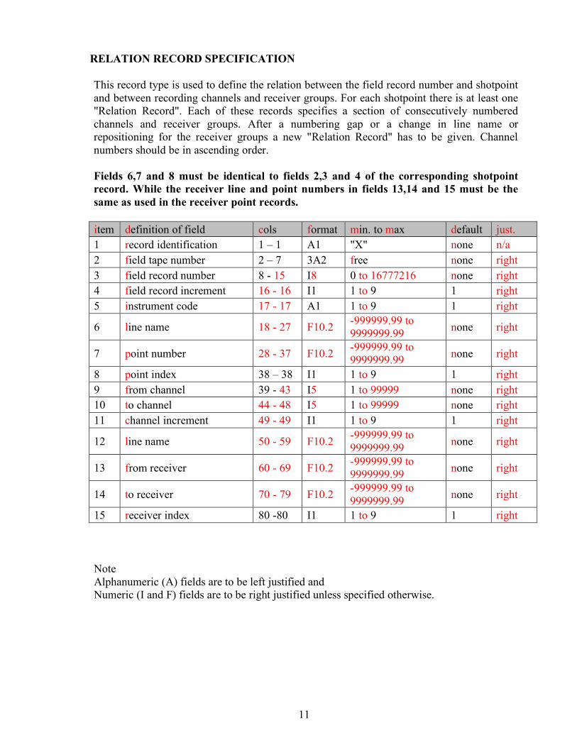
RELATION RECORD SPECIFICATION This record type is used to define the relation between the field record number and shotpoint and between recording channels and receiver groups. For each shotpoint there is at least one "Relation Record". Each of these records specifies a section of consecutively numbered channels and receiver groups. After a numbering gap or a change in line name or repositioning for the receiver groups a new "Relation Record" has to be given. Channel numbers should be in ascending order. Fields 6,7 and 8 must be identical to fields 2,3 and 4 of the corresponding shotpoint record. While the receiver line and point numbers in fields 13,14 and 15 must be the same as used in the receiver point records. item definition of field cols format min. to max default just. 1 record identification 1 – 1 A1 "X" none n/a 2 field tape number 2 – 7 3A2 free none right 3 field record number 8 - 15 I8 0 to 16777216 none right 4 field record increment 16 - 16 I1 1 to 9 1 right 5 instrument code 17 - 17 A1 1 to 9 1 right
6 line name 18 - 27 F10.2 -999999.99 to 9999999.99 none right
7 point number 28 - 37 F10.2 -999999.99 to 9999999.99 none right
8 point index 38 – 38 I1 1 to 9 1 right 9 from channel 39 - 43 I5 1 to 99999 none right 10 to channel 44 - 48 I5 1 to 99999 none right 11 channel increment 49 - 49 I1 1 to 9 1 right
12 line name 50 - 59 F10.2 -999999.99 to 9999999.99 none right
13 from receiver 60 - 69 F10.2 -999999.99 to 9999999.99 none right
14 to receiver 70 - 79 F10.2 -999999.99 to 9999999.99 none right
15 receiver index 80 -80 I1 1 to 9 1 right
Note Alphanumeric (A) fields are to be left justified and Numeric (I and F) fields are to be right justified unless specified otherwise.
12
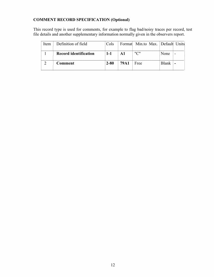
COMMENT RECORD SPECIFICATION (Optional)
This record type is used for comments, for example to flag bad/noisy traces per record, test file details and another supplementary information normally given in the observers report.
____________________________________________________________________ Item Definition of field Cols Format Min.to Max. Default Units
____________________________________________________________________ 1 Record identification 1-1 A1 "C" None -
____________________________________________________________________ 2 Comment 2-80 79A1 Free Blank -
____________________________________________________________________
13
HEADER RECORD DESCRIPTION
The text in bold type face are the parameter descriptions to be entered, left justified, into positions 5-32. The text in italics are examples of parameters to be entered, left justified, into positions 33-80. Positions 33 and 34 must always contain the instrument or receiver or source code. To enable parsing of free format (12A4) parameter fields the following rule should be used "The parameters entered into positions 33-80 must be separated by a comma and the parameter string must be terminated by a semi colon. Parameter text cannot contain commas ',' or semi colons';' ". N.B. All units of distance are in meters except the grid coordinates whose units are defined by H20 and can be converted to meters using the conversion factor defined by H201. H00 SPS format version num The format version number should be in this format. Example: SPS 2.1; H01 Description of survey area The name of the country, survey area, survey type (land:
L2D/L3D or Transition zone: TZ2D/TZ3D) and project number. Example: The Netherlands,Dordrecht,L3D,0090GA; H02 Date of survey The date of recording first shotpoint of survey and the last date of
survey on this file. Example: 21.05.1990,28.051990; H021 Post-plot date of issue The date when this tape or disc was issued and confirmed
checked. Example: 30.05.90; H022 Tape/disk identifier Example: 0090GA0; H023 Line sequence number The line sequence number allows more than one production
line per tape as long as a unique combination of field file number and line sequence number are used per storage unit. Example:5;
H03 Client The client's company name. Example: NAM; H04 Geophysical contractor The company name of the main seismic contractor, and the
seismic party name. Example: Prakla Seismos,SON 1; H05 Positioning contractor The company name of contractor or sub-contractor
responsible for the positioning/survey control in the field. Example: Prakla Seismos, H06 Pos. proc. contractor The company name of contractor or sub-contractor responsible
for the post processing of the positioning data. Example: Prakla Seismos,SON 1; H07 Field computer system(s) The acquisition management system name, name of
seismic recording instrument, and the method of direct transfer to/from the seismic recording instrument (if no direct transfer enter "manual entry").
Examples: CDB,SN368/FLUKE,FDOS discs; or None,SN368,manual entry;
14
H08 Coordinate location The description of what the coordinates refer to.
Example: centre of source pattern and centre of receiver pattern; H09 Offset to coord. location The offset from a vessel or vehicle reference position to
coordinate location as defined in H08, including method of angular offset used. Example: 170M,180DEG from vessel gyro heading;
H10 Clock time w.r.t. GMT The number of hours that the local (clock) time is behind or
ahead of GMT. Examples:+2; or -6; or 0; H11 Spare H12 Geodetic datum,-spheroid Datum name, spheroid name, semi major axis (a), inverse
flattening (l/f) as used for survey. Example: RD datum Bessel 1841 6377397.155 299.15281 H13 Spare H14 Geodetic datum parameters Datum transformation parameters to WGS84
(dx,dy,dz,rx,ry,rz,ds) as used for survey. Example: 595.000 11.300 478.900 0.000 0.000 0.000 0.000
The datum transformation parameters are defined by the following model: x dx 1 -rz +ry x y = dy + |scale| * +rz 1 -rx * y z (2) dz -ry +rx 1 z (l) where: x,y,z are the geocentric cartesian coordinates in meters dx,dy,dz are
translation parameters in meters rx,ry,rz are clockwise rotations defined in arcsecs, but converted to radians for use in the formula. Scale is [l+ds(l0E-6)], where ds is in parts per million.
For this example (l) is RD datum, (2) is WGS84 datum. H15 Spare H16 Spare H17 Vertical datum description Name, type (i.e. equipotential, LAT or spheroidal),
origin (name or lat,long) and undulation of vertical datum with respect to WGS84. Examples: NAP, Equipotential, Amsterdam, 0; or
MSL-Syria, Equipotential, 34 degr N, 38 degr E, 23.6m; H18 Projection type Type of map projection used. Example: Transverse Mercator; Hl9 Projection zone Zone and hemisphere for UTM projections. Example: Zone 30, North;
15
H20 Description of grid units Unit of coordinates. Examples: Meters; or International Feet; or Indian Feet; or American Feet; H201 Factor to meter The multiplication factor to convert grid units to meters. For
American Feet the factor is Examples: 0.30480061 H210 Lat. of standard parallel(s) Latitude of standard parallel(s) as required for projection
as per H18, in dddmmss.sss N/S. For 2 standard parallels of 5 degr N and 10 degr N. Example: 0050000.0000100000.000N
H220 Long. of central meridian Longitude of central meridian as required for projection
as per H18 above, in dddmmss.sss E/W. For 15 degr 30 min. Example: 0153000.000E H231 Grid origin Latitude and longitude of the grid origin in dddmmss.sss N/S
dddmmss.sss E/W. For 5 degr N and 15 degr 10 min and 25 sec. Example: 0050000.000N0151025.000E H232 Grid coord. at origin Grid coordinates (Eastings and Northings) at the origin of the
projection system. For false Easting of 500000 and false Northing of 0. Example: 50000000.0E 0.00N
H241 Scale factor Scale factor for defined projection. Example: 0.9996000000 H242 Lat., Long. scale factor Latitude and longitude at which the scale factor (H241) is
defined. Example: 0050000.000N 151025.000E H256 Lat., Long. initial line The two points defining the initial line of projection, as latl,
longl, lat2, long2. For 5 degr N, 20 degr E, 10 degr N, 30 degr E. Example:0050000.000N0200000.000E0100000.000N0300000.000E
H257 Circular bearing of H256 This is the true bearing to the east in the origin of the
initial line of projection in dddmmss.ssss (max of 360 degrees). Example: 1200000.0000 H258 Quadrant bearing of H256 Quadrant bearing of the initial line of projection in N/S
ddmmss.sss E/W. Example: S300000.000E H259 Angle from skew The angle between the skew and the rectified (North oriented) grid,
in dddmmsss.ssss. Example: 0883000.0000 H26 Free format in positions 5-80 Any other information can be included using header
records of this type. H30 Project code and description A six character code, the survey area name and survey
type (see H01) Example: 0090GA,Dordrecht ,L3D;
16
H31 Line number format (Obsolete) Specifies the internal format of the line number field in the data records. The specification shall be-
NAME1(POS1:LEN1),NAME2(POS2:LEN2),NAME3(POS3:LEN3); Where NAMEn is the name of the sub-identifier, POSn is the first character position
within the line number field and LENn is the length of the sub field. Example: BLOCK(1:4),STRIP(5:4),LINE NUMBER(9:8); If no sub division of the field is required then enter 'LINE NUMBER(1:16);'
Seismic instrument header records The user must define the set of code definitions for surveys, areas and vintages. Header record types H400-H419 are to be used to define tables for the first instrument code, and H420-H439 for the second up to H560-H579 for the ninth code. A new table must be defined, with a different code, for each instrument used or if any parameter in the table is changed. The instrument code must always be in col 33-34, for example '1,' to '9,' H400 Type,Model,Polarity The type and model name of seismic recording instrument, the
unique model number of the instrument and the polarity defined as SEG or NON SEG. The definition of SEG is "A compression shall be recorded as a negative number on tape and displayed as a downward deflection on monitor records". Example: 1,SN368+LXU,12345,SEG;
H401 Crew name,Comment The name of the crew and any other comments. Example: 1,Prakla SON 1; H402 Sample int.,Record Length The recording sample rate and the record length on tape.
Example: 1,2MSEC,6SEC; H403 Number of channels The number of channel per record. Example: 1,480; H404 Tape type,format,density The type of tape (9track or cartridge), recording format of
the data on tape and the recording density. Example: 1,9 track,SEGD,6250; H405 Filter_alias Hz,dB pnt,slope The anti alias or high cut filter setting of the recording
instrument or field boxes specified in hertz, the dB level at the frequency value and the filter slope in dB per octave.
Example: 177HZ,-6DB,72 DB/OCT; H406 Filter_notch Hz,-3dB points The centre frequency of the notch filter setting of the
recording instrument or field boxes sepcified in hertz and the frequency values at the -3dB points.
Examples: 1,NONE; or 1,50,45,55; H407 Filter_low Hz,dB pnt,slope The low cut filter setting of the recording instrument or
field boxes specified in hertz, the dB level at the frequency value and the filter slope in dB per octave.
Examples: 1,NONE; or 1,8HZ,-3DB,18 DB/OCT;
17
H408 Time delay,FTB-SOD app Y/N The value of any time delay and if the delay
between field time break and start of data has been applied to the seismic data recorded on tape. Example: 1,0 Msec,not applied;
H409 Multi component recording Describes the components being recorded and their
recording order on consecutive channels, allowed values are'X','Y','Z'. Examples: 1,Z; or 1,Z,X,Y; H410 Aux. channel 1 contents Describes the contents of a auxilliary channel Examples: 1,FTB; or 1,NONE; H411 Aux. channel 2 contents H412 Aux. channel 3 contents H413 Aux. channel 4 contents H414 Spare | H419 Spare
Seismic receiver header records The user must define the set of code definitions for surveys, areas and vintages. Header record types H600-H609 are to be used to define tables for the first receiver code, and H610-H619 for the second up to H690-699 for the tenth code. A new table must be defined, with a different code, for each receiver type used or if any parameter in the table is changed. The receiver code must always be in col 33-34, examples of possible codes: G1..to.G9 for geophones H1..to.H9 for hydrophones R1..to.R9 for multi comp. and other types PM = Permanent marker KL = Kill or omit receiver station H600 Type,model,polarity The type (land geophone, marsh geophone, hydrophone),
model name of seismic detector and the polarity defined as SEG or NON SEG. The definition of SEG is "A compression shall be recorded as a negative number on tape and displayed as a downward deflection on monitor records". Example: G1,SM-4,1234,SEG;
H601 Damping coeff,natural freq. Example: G1,0.68,10Hz; H602 Nunits,len(X),width(Y) The number of elements in the receiver group, the in-line
and the cross-line dimension of the receiver group pattern. Example: G1,12,25M,6M; H603 Unit spacing X,Y The distance between each element of the receiver group, in-line
(X), and cross-line (Y). Example: G1,4M,6M; H604 Spare | H609 Spare
18
Seismic source header records
The user must define the set of code definitions for surveys, areas and vintages. Header record types H700-H719 are to be used to define tables for the first source code, and H720-H739 for the second up to H880-899 for the tenth code. A new table must be defined, with a different code, for each source type used or if any parameter in the table is changed. The source code must always be in col 33-34, examples of possible codes: V1..to.V9 for vibroseis E1..to.E9 for explosive A1..to.A9 for air gun W1..to.W9 for water gun S1..to.S9 for other types. KL = Kill or omit shotpoint H700 Type,model,polarity Source type (explosive,air gun etc), make or model, and the
polarity defined as SEG or NON SEG. The definition of SEG is "A compression shall be recorded as a negative number on tape and displayed as a downward deflection on monitor records".
Examples: E1,EXPLOSIVE,SEISMOGEL 125gram,SEG; or V1,VIBROSEIS,METRZ 22,SEG EQU; H701 Size,vert. stk fold The total charge size, force or air volume of the source pattern, the
vertical fold of stack or number of sweeps per VP. Examples: E1,1000 gram,1; or V1,93 kN,1 SWEEP/VP; H702 Nunits,len(X),width(Y) The number of elements in the source pattern, the in-line and
the cross-line dimension of the source pattern. Examples: E1,6,25M,0M; or V1,4 VIBS,25M,45M; H703 Unit spacing X,Y The distance between each element of the source pattern, in-line
(X), and cross-line (Y). Examples: E1,5M,0; or V1,8M,15M; Following records are only required if source type= Vibroseis V1..V9 H704 Control type The type of control used. Example: V1,GND FORCE PHASE&L LOCK; H705 Correlator,noise supp The type of correlator/stacker, and the type of noise
suppression applied before summing. Example: V1,SERCELCS-2502,NO NOISE SUPP; H706 Sweep type,length The type and length of the sweep. Example: V1,LINEAR,30 SECONDS; H707 Sweep freq start,end The start and end frequency of the sweep.
Example: V1,5HZ,60HZ; H708 Taper,length start,end The type of taper and the taper length (start and end).
Example: V1,COSINE,500MSEC,500MSEC; H709 Spare
19
H710 Spare Following records are only required if source type= Explosive E1..E9 H711 Nom. shot depth,charge len. The nominal shot depth, and the length of the charge.
Example: E1,15M,1M; H712 Nom. soil,drill method The nominal type of soil or near surface medium, and the
method of drilling (flushing,hand auger,portable drill unit etc). Example: E1,CLAY,PORTABLE UNITS; H713 Weathering thickness The nominal depth to the base of weathered layer. Example: E1,8-12M; H714 Spare H715 Spare Following records are only required if source type = air gun A1..A9 water gun W1..W9 H716 P-P bar m,prim/bubble The Peak-peak output in bar meters, and the primary to
bubble ratio measured through a 0-125Hz filter at a depth of 6 meters. Example: A1,50,13:1; H717 Air pressure psi The nominal operating air pressure. Example: A1,2000PSI; H718 No. sub arrays,nom depth The number of sub arrays and the nominal towing depth.
Example: A1,3,5.5M; H719 Spare
Quality Control check records H990 R,S,X file quality control The Date and time of the Q.C. check, and the name of the
person who performed the quality control of the file. Example: 01JUN90,0930,Mr J Smith; H991 Coord. status final/prov The status of the coordinates contained in the R and S files
final or provisional), the date and time of the status, the name of the surveyor responsible for the coordinate integrity. Example: Final,01jun90,0930,Mr J. Jansen;
20
POINT RECORD DESCRIPTION 2 Line name: Identifier for the shotpoint or receiver line. It is a numeric number with
the format of F10.2. If no decimal point is provided it should be taken as implied. It can be composed of a block or strip number and a line number. The internal format of this field must be defined in the header.
3 Point number: Identifier for the shotpoint or receiver group number defined as the
centre of the source or receiver array as staked out in the field. The value should be read as a numeric F10.2 and be right justified.
4 Point index: Identifier for the shotpoint or receiver index. Shotpoint: To be 1 for original shot within the grid cell denoted by fields 2 and 3, and
be incremented by 1 for each subsequent shot within the same grid cell. Exceptions: shots to be vertically stacked (unsummed vibroseis).
Receiver: To be 1 for the original positioning of a receiver group, and be incremented by 1 every time the receiver group is moved or repositioned, even when put back to any previous position.
5 Point code: A shotpoint or receiver code which is defined in the header by a table that
describes the characteristics of the source or receiver group used at the point. 6 Static correction: The shotpoint or receiver static correction defined as a static time
shift in Msec. that has been computed in the field to correct any seismic recording for the effects of elevation, weathering thickness, or weathering velocity at the point. The correction should be with reference to the seismic datum as defined by field 8 of this record. If no static was computed leave 'blank'.
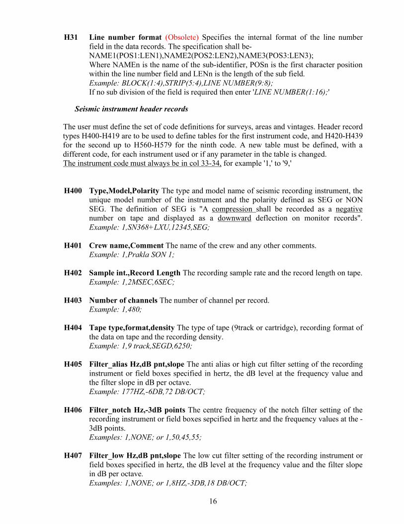
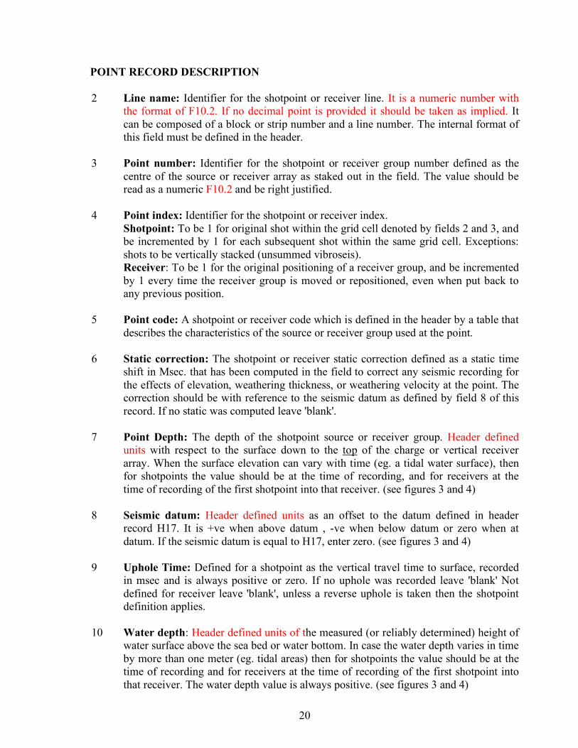
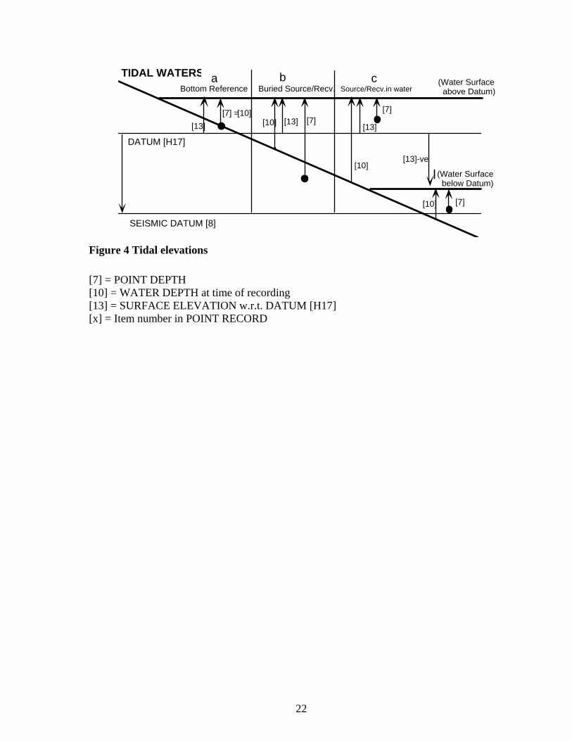
7 Point Depth: The depth of the shotpoint source or receiver group. Header defined
units with respect to the surface down to the top of the charge or vertical receiver array. When the surface elevation can vary with time (eg. a tidal water surface), then for shotpoints the value should be at the time of recording, and for receivers at the time of recording of the first shotpoint into that receiver. (see figures 3 and 4)
8 Seismic datum: Header defined units as an offset to the datum defined in header
record H17. It is +ve when above datum , -ve when below datum or zero when at datum. If the seismic datum is equal to H17, enter zero. (see figures 3 and 4)
9 Uphole Time: Defined for a shotpoint as the vertical travel time to surface, recorded
in msec and is always positive or zero. If no uphole was recorded leave 'blank' Not defined for receiver leave 'blank', unless a reverse uphole is taken then the shotpoint definition applies.
10 Water depth: Header defined units of the measured (or reliably determined) height of
water surface above the sea bed or water bottom. In case the water depth varies in time by more than one meter (eg. tidal areas) then for shotpoints the value should be at the time of recording and for receivers at the time of recording of the first shotpoint into that receiver. The water depth value is always positive. (see figures 3 and 4)
21
11 Map grid easting: The easting for the point, in the coordinate system defined by header record H13.
12 Map grid northing: The northing for the point, in the coordinate system defined by
header record H13. To accommodate large TM northing values for surveys straddling the equator, this field format has one more digit than UKOOA P1/90.
13 Surface elevation: The topographical surface with respect to the vertical datum
defined by header record H17. The surface elevation is +ve when above datum , -ve when below datum or zero when at datum. When the surface elevation with respect to the datum can vary with time (eg. a tidal water surface) Then for shotpoints the value should be at the time of recording, and for receivers at the time of recording of the first shotpoint into that receiver. (see figures 3 and 4)
14 Day of year: The julian day. For shotpoints the value should be the day of recording,
and for receivers the day of recording of the first shotpoint into that receiver. When the survey continues into the next year, the day should keep increasing and not be reset to zero - 1st January would then be 366 or 367.
15 Time hhmmss: The time taken from the clock of the master seismic recording
instrument. For shotpoints the value should be the time of recording, and for receivers the time of recording of the first shotpoint into that receiver.
LAND AREAS
DATUM [H17]
SEISMIC DATUM [8]
[13][13]
[10]= 0
[7]
a b c Surface Source/Recv. Source/Recv.in water
[10] [7] [13]
[7]=[10]= 0 Water Surface at time of recording
TOPO SURFACE
Buried Source/Recv.
Figure 3 Land elevations
22
TIDAL WATERS
DATUM [H17]
SEISMIC DATUM [8]
[13][7] =
[10] [7] [13][13]
[10]
[7] [10]
a b c Bottom Reference
[13]-ve
[10] [7]
Buried Source/Recv. Source/Recv.in water
(Water Surface below Datum)
(Water Surface above Datum)
Figure 4 Tidal elevations [7] = POINT DEPTH [10] = WATER DEPTH at time of recording [13] = SURFACE ELEVATION w.r.t. DATUM [H17] [x] = Item number in POINT RECORD

23
RELATION RECORD DESCRIPTION 2 Field tape number: The identifier of the data carrier (tape) on which the seismic
recording of the spread defined by this record is written. To accommodate alphanumeric tape numbers this field is defined as 3A2 and is left justified in the field.
3 Field record number:The number of the seismic recording given by the field
instrument used to record the spread defined by this record. 4 Field record increment: The increment for the field record numbers, defined to allow
several consecutive records which recorded the same shotpoint and spread to be defined by one 'X' record' (eg. unsummed vibroseis records).
5 Instrument code: Defined in the header by a table that describes the type, and settings
of the instrument used to record the spread defined by this record. 6 Line name: Identifier for the shotpoint line.Must be identical to field 2 of the
corresponding shotpoint record. 7 Point number: Identifier for the shotpoint number. Must be identical to field 3 of the
corresponding shotpoint record. 8 Point index: Identifier for the shotpoint index. Must be identical to field 4 of the
corresponding shotpoint record. 9 From channel: The seismic channel number as recorded in the seismic trace header
corresponding to the data from the receiver group number defined by fields 12 and 13 of this record.
10 To channel: The seismic channel number as recorded in the seismic trace header
corresponding to the data from the receiver group number defined by fields 12 and 14 of this record.
11 Channel increment: This field can be used for multi-component receivers when the
three components (Z,X and Y) for one receiver point are recorded on three consecutive seismic channels, Then one 'X' record can define three components using a channel increment of 3. The components and their order are defined by the instrument code.
12 Line name: Identifier for the receiver line for the range of receivers defined by fields
13 and 14 of this record. The identifier must be identical to field 2 of the receiver point records that correspond to the same receiver line.
13 From receiver: Identifier for the receiver group number that corresponds to the From
channel number defined in field 9. The identifier must be identical to field 3 of the receiver point record that corresponds to the same receiver group.
14 To receiver: Identifier for the receiver group number that corresponds to the To
channel number defined in field 10. The identifier must be identical to field 3 of the receiver point record that corresponds to the same receiver group.

24
15 Receiver index: The receiver index value for the range of receivers defined by fields
12,13 and 14 of this record. The combination of fields 12,13,15 and 12,14,15 must correspond to the same range of receivers as defined by records in the receiver point file.
25
APPENDIX 1 - EXAMPLE OF SPS FORMAT (files shown for example only-not necessarily complete)
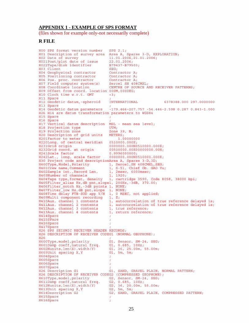
R FILE H00 SPS format version number SPS 2.1; H01 Description of survey area Area A, Sparse 3-D, EXPLORATION; H02 Date of survey 11.01.2006,21.01.2006; H021Post/plot date of issue 22.01.2006; H022Tape/disk identifier B79437-B79503; H03 Client SEG; H04 Geophysical contractor Contractor A; H05 Positioning contractor Contractor A; H06 Pos. proc. contractor Contractor A; H07 Field computer system(s) Sercel SN 408CMXL; H08 Coordinate location CENTRE OF SOURCE AND RECEIVER PATTERNS; H09 Offset from coord. location 000M,000DEG; H10 Clock time w.r.t. GMT +3; H11 Spare ; H12 Geodetic datum,-spheroid INTERNATIONAL 6378388.000 297.0000000 H13 Spare ; H14 Geodetic datum parameters -179.466-207.757 -54.446-2.598 0.287 0.843-1.000 H26 H14 are datum transformation parameters to WGS84 H15 Spare ; H16 Spare ; H17 Vertical datum description MSL - mean sea level; H18 Projection type UTM; H19 Projection zone Zone 39, N; H20 Description of grid units METERS; H201Factor to meter 1.00000000 H220Long. of central meridian 0510000.000E; H231Grid origin 0000000.000N0510000.000E; H232Grid coord. at origin 00500000.00E00000000.00N; H241Scale factor 0.9996000000; H242Lat., long. scale factor 0000000.000N0510000.000E; H30 Project code and descriptionArea A, Sparse 3-D,3D; H400Type,Model,Polarity 1, Sercel,SN 408CMXL,SEG; H401Crew name,Comment 1, S-51, Chief Ob. GAO Yu; H402Sample int.,Record Len. 1, 2msec, 6000msec; H403Number of channels 1, 1920; H404Tape type,format, density 1, cartridge 3590, Code 8058, 38000 bpi; H405Filter_alias Hz,dB pnt,slope1, 200Hz,-3dB, 370.00; H406Filter_notch Hz,-3dB points 1, NONE; H407Filter_low Hz,dB pnt,slope 1, NONE; H408Time delay FTB-SOD app Y/N 1, 0 MSEC, not applied; H409Multi component recording 1, Z; H410Aux. channel 1 contents 1, autocorrelation of true reference delayed 1s; H411Aux. channel 2 contents 1, autocorrelation of true reference delayed 1s; H412Aux. channel 3 contents 1, true reference; H413Aux. channel 4 contents 1, return reference; H414Spare ; H415SPare ; H416Spare ; H417Spare ; H26 SPS SEISMIC RECEIVER HEADER RECORDS; H26 DESCRIPTION OF RECEIVER CODEG1 (NORMAL GEOPHONE); H26 ; H600Type,model,polarity G1, Sensor, SM-24, SEG; H601Damp coeff,natural freq. G1, 0.685, 10Hz; H602Nunits,len(X),width(Y) G1, 36, 25.00m, 55.00m; H603Unit spacing X,Y G1, 5m, 5m; H604Spare ; H605Spare ; H606Spare ; H607Spare ; H26 Description G1 G1, SAND, GRAVEL PLAIN, NORMAL PATTERN; H26 DESCRIPTION OF RECEIVER CODEG2 (COMPRESSED GEOPHONE); H610Type,model,polarity G2, Sensor, SM-24, SEG; H611Damp coeff,natural freq. G2, 0.685, 10Hz; H612Nunits,len(X),width(Y) G2, 36, 20.00m, 55.00m; H613Unit spacing X,Y G2, 5m, 5m; H614Description G2 G2, SAND, GRAVEL PLAIN, COMPRESSED PATTERN; H615Spare ; H616Spare ;
26
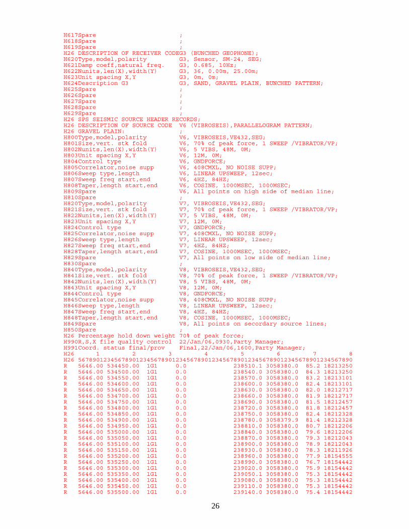
H617Spare ; H618Spare ; H619Spare ; H26 DESCRIPTION OF RECEIVER CODEG3 (BUNCHED GEOPHONE); H620Type,model,polarity G3, Sensor, SM-24, SEG; H621Damp coeff,natural freq. G3, 0.685, 10Hz; H622Nunits,len(X),width(Y) G3, 36, 0.00m, 25.00m; H623Unit spacing X,Y G3, 0m, 0m; H624Description G3 G3, SAND, GRAVEL PLAIN, BUNCHED PATTERN; H625Spare ; H626Spare ; H627Spare ; H628Spare ; H629Spare ; H26 SPS SEISMIC SOURCE HEADER RECORDS; H26 DESCRIPTION OF SOURCE CODE V6 (VIBROSEIS),PARALLELOGRAM PATTERN; H26 GRAVEL PLAIN: ; H800Type,model,polarity V6, VIBROSEIS,VE432,SEG; H801Size,vert. stk fold V6, 70% of peak force, 1 SWEEP /VIBRATOR/VP; H802Nunits,len(X),width(Y) V6, 5 VIBS, 48M, 0M; H803Unit spacing X,Y V6, 12M, 0M; H804Control type V6, GNDFORCE; H805Correlator,noise supp V6, 408CMXL, NO NOISE SUPP; H806Sweep type,length V6, LINEAR UPSWEEP, 12sec; H807Sweep freq start,end V6, 4HZ, 84HZ; H808Taper,length start,end V6, COSINE, 1000MSEC, 1000MSEC; H809Spare V6, All points on high side of median line; H810Spare ; H820Type,model,polarity V7, VIBROSEIS,VE432,SEG; H821Size,vert. stk fold V7, 70% of peak force, 1 SWEEP /VIBRATOR/VP; H822Nunits,len(X),width(Y) V7, 5 VIBS, 48M, 0M; H823Unit spacing X,Y V7, 12M, 0M; H824Control type V7, GNDFORCE; H825Correlator,noise supp V7, 408CMXL, NO NOISE SUPP; H826Sweep type,length V7, LINEAR UPSWEEP, 12sec; H827Sweep freq start,end V7, 4HZ, 84HZ; H828Taper,length start,end V7, COSINE, 1000MSEC, 1000MSEC; H829Spare V7, All points on low side of median line; H830Spare ; H840Type,model,polarity V8, VIBROSEIS,VE432,SEG; H841Size,vert. stk fold V8, 70% of peak force, 1 SWEEP /VIBRATOR/VP; H842Nunits,len(X),width(Y) V8, 5 VIBS, 48M, 0M; H843Unit spacing X,Y V8, 12M, 0M; H844Control type V8, GNDFORCE; H845Correlator,noise supp V8, 408CMXL, NO NOISE SUPP; H846Sweep type,length V8, LINEAR UPSWEEP, 12sec; H847Sweep freq start,end V8, 4HZ, 84HZ; H848Taper,length start,end V8, COSINE, 1000MSEC, 1000MSEC; H849Spare V8, All points on secordary source lines; H850Spare ; H26 Percentage hold down weight 70% of peak force; H990R,S,X file quality control 22/Jan/06,0930,Party Manager; H991Coord. status final/prov Final,22/Jan/06,1600,Party Manager; H26 1 2 3 4 5 6 7 8 H26 5678901234567890123456789012345678901234567890123456789012345678901234567890 R 5646.00 534450.00 1G1 0.0 238510.1 3058380.0 85.2 18213250 R 5646.00 534500.00 1G1 0.0 238540.0 3058380.0 84.3 18213250 R 5646.00 534550.00 1G1 0.0 238570.0 3058380.0 83.2 18213101 R 5646.00 534600.00 1G1 0.0 238600.0 3058380.0 82.4 18213101 R 5646.00 534650.00 1G1 0.0 238630.0 3058380.0 82.0 18212717 R 5646.00 534700.00 1G1 0.0 238660.0 3058380.0 81.9 18212717 R 5646.00 534750.00 1G1 0.0 238690.0 3058380.0 81.5 18212457 R 5646.00 534800.00 1G1 0.0 238720.0 3058380.0 81.8 18212457 R 5646.00 534850.00 1G1 0.0 238750.0 3058380.0 82.4 18212328 R 5646.00 534900.00 1G1 0.0 238780.0 3058379.9 81.4 18212328 R 5646.00 534950.00 1G1 0.0 238810.0 3058380.0 80.7 18212206 R 5646.00 535000.00 1G1 0.0 238840.0 3058380.0 79.6 18212206 R 5646.00 535050.00 1G1 0.0 238870.0 3058380.0 79.3 18212043 R 5646.00 535100.00 1G1 0.0 238900.0 3058380.0 78.9 18212043 R 5646.00 535150.00 1G1 0.0 238930.0 3058380.0 78.3 18211926 R 5646.00 535200.00 1G1 0.0 238960.0 3058380.0 77.9 18154555 R 5646.00 535250.00 1G1 0.0 238990.0 3058380.0 76.7 18154442 R 5646.00 535300.00 1G1 0.0 239020.0 3058380.0 75.9 18154442 R 5646.00 535350.00 1G1 0.0 239050.1 3058380.0 75.3 18154442 R 5646.00 535400.00 1G1 0.0 239080.0 3058380.0 75.3 18154442 R 5646.00 535450.00 1G1 0.0 239110.0 3058380.0 75.3 18154442 R 5646.00 535500.00 1G1 0.0 239140.0 3058380.0 75.4 18154442
27
R 5646.00 535550.00 1G1 0.0 239170.0 3058380.0 75.5 18154442 R 5646.00 535600.00 1G1 0.0 239200.0 3058380.0 75.7 18154442 R 5646.00 535650.00 1G1 0.0 239230.0 3058380.0 76.8 18154442 R 5646.00 535700.00 1G1 0.0 239260.0 3058380.0 77.7 18154442 R 5646.00 535750.00 1G1 0.0 239290.0 3058380.0 78.5 18154442 R 5646.00 535800.00 1G1 0.0 239320.0 3058380.0 78.9 18154442 R 5646.00 535850.00 1G1 0.0 239350.0 3058380.0 79.0 18154442 R 5646.00 535900.00 1G1 0.0 239380.0 3058380.0 78.9 18152739 R 5646.00 535950.00 1G1 0.0 239410.0 3058380.0 80.1 18152615 R 5646.00 536000.00 1G1 0.0 239440.0 3058380.0 78.1 18152615 R 5646.00 536050.00 1G1 0.0 239470.0 3058380.0 76.5 18151242 R 5646.00 536100.00 1G1 0.0 239500.1 3058380.0 74.6 18151242 R 5646.00 536150.00 1G1 0.0 239530.0 3058380.0 73.1 18151242 R 5646.00 536200.00 1G1 0.0 239560.0 3058380.0 72.1 18151242 R 5646.00 536250.00 1G1 0.0 239590.0 3058380.0 71.4 18151114 R 5646.00 536300.00 1G1 0.0 239620.0 3058380.0 70.5 18151114 R 5646.00 536350.00 1G1 0.0 239650.0 3058380.0 70.1 18151015 R 5646.00 536400.00 1G1 0.0 239680.0 3058380.0 68.6 18151015 R 5646.00 536450.00 1G1 0.0 239710.0 3058380.0 67.1 18144415 R 5646.00 536500.00 1G1 0.0 239740.0 3058380.0 66.3 18144415 R 5646.00 536550.00 1G1 0.0 239770.0 3058380.0 65.9 18144234 R 5646.00 536600.00 1G1 0.0 239800.0 3058380.0 65.8 18144234 R 5646.00 536650.00 1G1 0.0 239830.0 3058380.0 64.9 18144125 R 5646.00 536700.00 1G1 0.0 239860.0 3058380.0 64.8 18144125 R 5646.00 536750.00 1G1 0.0 239890.0 3058380.0 63.7 18142825
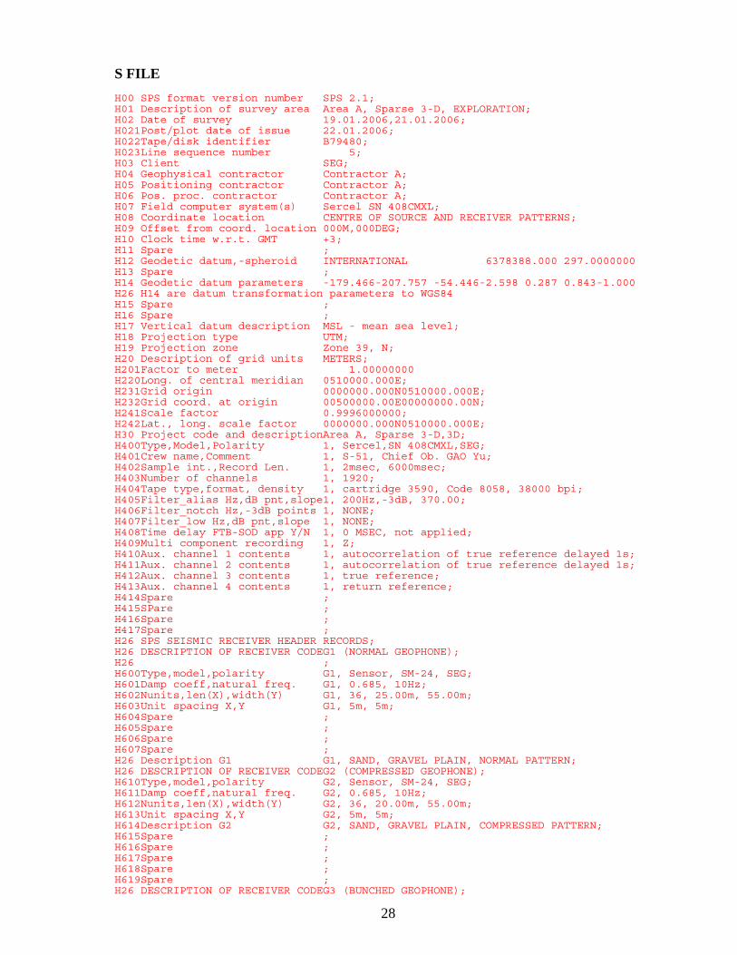
28
S FILE H00 SPS format version number SPS 2.1; H01 Description of survey area Area A, Sparse 3-D, EXPLORATION; H02 Date of survey 19.01.2006,21.01.2006; H021Post/plot date of issue 22.01.2006; H022Tape/disk identifier B79480; H023Line sequence number 5; H03 Client SEG; H04 Geophysical contractor Contractor A; H05 Positioning contractor Contractor A; H06 Pos. proc. contractor Contractor A; H07 Field computer system(s) Sercel SN 408CMXL; H08 Coordinate location CENTRE OF SOURCE AND RECEIVER PATTERNS; H09 Offset from coord. location 000M,000DEG; H10 Clock time w.r.t. GMT +3; H11 Spare ; H12 Geodetic datum,-spheroid INTERNATIONAL 6378388.000 297.0000000 H13 Spare ; H14 Geodetic datum parameters -179.466-207.757 -54.446-2.598 0.287 0.843-1.000 H26 H14 are datum transformation parameters to WGS84 H15 Spare ; H16 Spare ; H17 Vertical datum description MSL - mean sea level; H18 Projection type UTM; H19 Projection zone Zone 39, N; H20 Description of grid units METERS; H201Factor to meter 1.00000000 H220Long. of central meridian 0510000.000E; H231Grid origin 0000000.000N0510000.000E; H232Grid coord. at origin 00500000.00E00000000.00N; H241Scale factor 0.9996000000; H242Lat., long. scale factor 0000000.000N0510000.000E; H30 Project code and descriptionArea A, Sparse 3-D,3D; H400Type,Model,Polarity 1, Sercel,SN 408CMXL,SEG; H401Crew name,Comment 1, S-51, Chief Ob. GAO Yu; H402Sample int.,Record Len. 1, 2msec, 6000msec; H403Number of channels 1, 1920; H404Tape type,format, density 1, cartridge 3590, Code 8058, 38000 bpi; H405Filter_alias Hz,dB pnt,slope1, 200Hz,-3dB, 370.00; H406Filter_notch Hz,-3dB points 1, NONE; H407Filter_low Hz,dB pnt,slope 1, NONE; H408Time delay FTB-SOD app Y/N 1, 0 MSEC, not applied; H409Multi component recording 1, Z; H410Aux. channel 1 contents 1, autocorrelation of true reference delayed 1s; H411Aux. channel 2 contents 1, autocorrelation of true reference delayed 1s; H412Aux. channel 3 contents 1, true reference; H413Aux. channel 4 contents 1, return reference; H414Spare ; H415SPare ; H416Spare ; H417Spare ; H26 SPS SEISMIC RECEIVER HEADER RECORDS; H26 DESCRIPTION OF RECEIVER CODEG1 (NORMAL GEOPHONE); H26 ; H600Type,model,polarity G1, Sensor, SM-24, SEG; H601Damp coeff,natural freq. G1, 0.685, 10Hz; H602Nunits,len(X),width(Y) G1, 36, 25.00m, 55.00m; H603Unit spacing X,Y G1, 5m, 5m; H604Spare ; H605Spare ; H606Spare ; H607Spare ; H26 Description G1 G1, SAND, GRAVEL PLAIN, NORMAL PATTERN; H26 DESCRIPTION OF RECEIVER CODEG2 (COMPRESSED GEOPHONE); H610Type,model,polarity G2, Sensor, SM-24, SEG; H611Damp coeff,natural freq. G2, 0.685, 10Hz; H612Nunits,len(X),width(Y) G2, 36, 20.00m, 55.00m; H613Unit spacing X,Y G2, 5m, 5m; H614Description G2 G2, SAND, GRAVEL PLAIN, COMPRESSED PATTERN; H615Spare ; H616Spare ; H617Spare ; H618Spare ; H619Spare ; H26 DESCRIPTION OF RECEIVER CODEG3 (BUNCHED GEOPHONE);
29
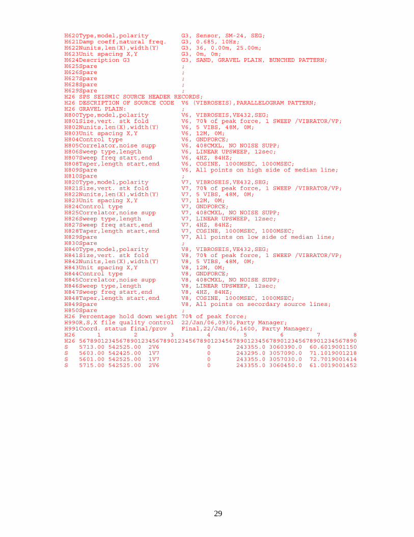
H620Type,model,polarity G3, Sensor, SM-24, SEG; H621Damp coeff,natural freq. G3, 0.685, 10Hz; H622Nunits,len(X),width(Y) G3, 36, 0.00m, 25.00m; H623Unit spacing X,Y G3, 0m, 0m; H624Description G3 G3, SAND, GRAVEL PLAIN, BUNCHED PATTERN; H625Spare ; H626Spare ; H627Spare ; H628Spare ; H629Spare ; H26 SPS SEISMIC SOURCE HEADER RECORDS; H26 DESCRIPTION OF SOURCE CODE V6 (VIBROSEIS),PARALLELOGRAM PATTERN; H26 GRAVEL PLAIN: ; H800Type,model,polarity V6, VIBROSEIS,VE432,SEG; H801Size,vert. stk fold V6, 70% of peak force, 1 SWEEP /VIBRATOR/VP; H802Nunits,len(X),width(Y) V6, 5 VIBS, 48M, 0M; H803Unit spacing X,Y V6, 12M, 0M; H804Control type V6, GNDFORCE; H805Correlator,noise supp V6, 408CMXL, NO NOISE SUPP; H806Sweep type,length V6, LINEAR UPSWEEP, 12sec; H807Sweep freq start,end V6, 4HZ, 84HZ; H808Taper,length start,end V6, COSINE, 1000MSEC, 1000MSEC; H809Spare V6, All points on high side of median line; H810Spare ; H820Type,model,polarity V7, VIBROSEIS,VE432,SEG; H821Size,vert. stk fold V7, 70% of peak force, 1 SWEEP /VIBRATOR/VP; H822Nunits,len(X),width(Y) V7, 5 VIBS, 48M, 0M; H823Unit spacing X,Y V7, 12M, 0M; H824Control type V7, GNDFORCE; H825Correlator,noise supp V7, 408CMXL, NO NOISE SUPP; H826Sweep type,length V7, LINEAR UPSWEEP, 12sec; H827Sweep freq start,end V7, 4HZ, 84HZ; H828Taper,length start,end V7, COSINE, 1000MSEC, 1000MSEC; H829Spare V7, All points on low side of median line; H830Spare ; H840Type,model,polarity V8, VIBROSEIS,VE432,SEG; H841Size,vert. stk fold V8, 70% of peak force, 1 SWEEP /VIBRATOR/VP; H842Nunits,len(X),width(Y) V8, 5 VIBS, 48M, 0M; H843Unit spacing X,Y V8, 12M, 0M; H844Control type V8, GNDFORCE; H845Correlator,noise supp V8, 408CMXL, NO NOISE SUPP; H846Sweep type,length V8, LINEAR UPSWEEP, 12sec; H847Sweep freq start,end V8, 4HZ, 84HZ; H848Taper,length start,end V8, COSINE, 1000MSEC, 1000MSEC; H849Spare V8, All points on secordary source lines; H850Spare ; H26 Percentage hold down weight 70% of peak force; H990R,S,X file quality control 22/Jan/06,0930,Party Manager; H991Coord. status final/prov Final,22/Jan/06,1600, Party Manager; H26 1 2 3 4 5 6 7 8 H26 5678901234567890123456789012345678901234567890123456789012345678901234567890 S 5713.00 542525.00 2V6 0 243355.0 3060390.0 60.6019001150 S 5603.00 542425.00 1V7 0 243295.0 3057090.0 71.1019001218 S 5601.00 542525.00 1V7 0 243355.0 3057030.0 72.7019001414 S 5715.00 542525.00 2V6 0 243355.0 3060450.0 61.0019001452
30
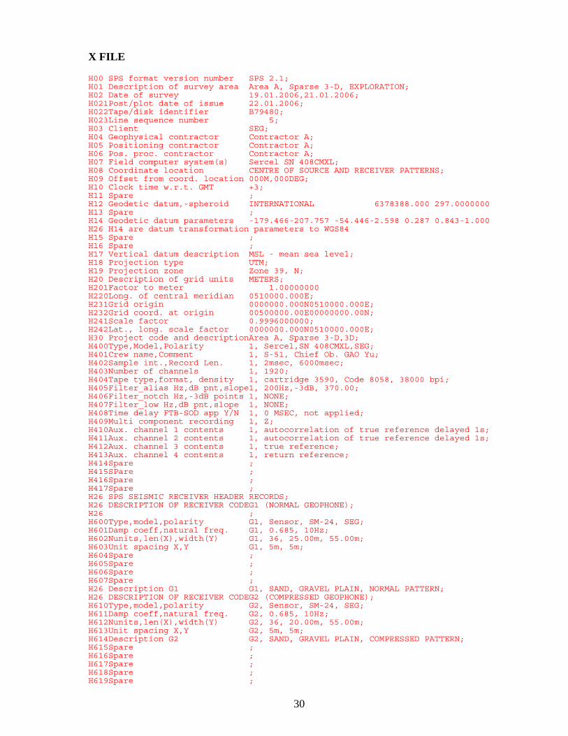
X FILE H00 SPS format version number SPS 2.1; H01 Description of survey area Area A, Sparse 3-D, EXPLORATION; H02 Date of survey 19.01.2006,21.01.2006; H021Post/plot date of issue 22.01.2006; H022Tape/disk identifier B79480; H023Line sequence number 5; H03 Client SEG; H04 Geophysical contractor Contractor A; H05 Positioning contractor Contractor A; H06 Pos. proc. contractor Contractor A; H07 Field computer system(s) Sercel SN 408CMXL; H08 Coordinate location CENTRE OF SOURCE AND RECEIVER PATTERNS; H09 Offset from coord. location 000M,000DEG; H10 Clock time w.r.t. GMT +3; H11 Spare ; H12 Geodetic datum,-spheroid INTERNATIONAL 6378388.000 297.0000000 H13 Spare ; H14 Geodetic datum parameters -179.466-207.757 -54.446-2.598 0.287 0.843-1.000 H26 H14 are datum transformation parameters to WGS84 H15 Spare ; H16 Spare ; H17 Vertical datum description MSL - mean sea level; H18 Projection type UTM; H19 Projection zone Zone 39, N; H20 Description of grid units METERS; H201Factor to meter 1.00000000 H220Long. of central meridian 0510000.000E; H231Grid origin 0000000.000N0510000.000E; H232Grid coord. at origin 00500000.00E00000000.00N; H241Scale factor 0.9996000000; H242Lat., long. scale factor 0000000.000N0510000.000E; H30 Project code and descriptionArea A, Sparse 3-D,3D; H400Type,Model,Polarity 1, Sercel,SN 408CMXL,SEG; H401Crew name,Comment 1, S-51, Chief Ob. GAO Yu; H402Sample int.,Record Len. 1, 2msec, 6000msec; H403Number of channels 1, 1920; H404Tape type,format, density 1, cartridge 3590, Code 8058, 38000 bpi; H405Filter_alias Hz,dB pnt,slope1, 200Hz,-3dB, 370.00; H406Filter_notch Hz,-3dB points 1, NONE; H407Filter_low Hz,dB pnt,slope 1, NONE; H408Time delay FTB-SOD app Y/N 1, 0 MSEC, not applied; H409Multi component recording 1, Z; H410Aux. channel 1 contents 1, autocorrelation of true reference delayed 1s; H411Aux. channel 2 contents 1, autocorrelation of true reference delayed 1s; H412Aux. channel 3 contents 1, true reference; H413Aux. channel 4 contents 1, return reference; H414Spare ; H415SPare ; H416Spare ; H417Spare ; H26 SPS SEISMIC RECEIVER HEADER RECORDS; H26 DESCRIPTION OF RECEIVER CODEG1 (NORMAL GEOPHONE); H26 ; H600Type,model,polarity G1, Sensor, SM-24, SEG; H601Damp coeff,natural freq. G1, 0.685, 10Hz; H602Nunits,len(X),width(Y) G1, 36, 25.00m, 55.00m; H603Unit spacing X,Y G1, 5m, 5m; H604Spare ; H605Spare ; H606Spare ; H607Spare ; H26 Description G1 G1, SAND, GRAVEL PLAIN, NORMAL PATTERN; H26 DESCRIPTION OF RECEIVER CODEG2 (COMPRESSED GEOPHONE); H610Type,model,polarity G2, Sensor, SM-24, SEG; H611Damp coeff,natural freq. G2, 0.685, 10Hz; H612Nunits,len(X),width(Y) G2, 36, 20.00m, 55.00m; H613Unit spacing X,Y G2, 5m, 5m; H614Description G2 G2, SAND, GRAVEL PLAIN, COMPRESSED PATTERN; H615Spare ; H616Spare ; H617Spare ; H618Spare ; H619Spare ;
31
H26 DESCRIPTION OF RECEIVER CODEG3 (BUNCHED GEOPHONE); H620Type,model,polarity G3, Sensor, SM-24, SEG; H621Damp coeff,natural freq. G3, 0.685, 10Hz; H622Nunits,len(X),width(Y) G3, 36, 0.00m, 25.00m; H623Unit spacing X,Y G3, 0m, 0m; H624Description G3 G3, SAND, GRAVEL PLAIN, BUNCHED PATTERN; H625Spare ; H626Spare ; H627Spare ; H628Spare ; H629Spare ; H26 SPS SEISMIC SOURCE HEADER RECORDS; H26 DESCRIPTION OF SOURCE CODE V6 (VIBROSEIS),PARALLELOGRAM PATTERN; H26 GRAVEL PLAIN: ; H800Type,model,polarity V6, VIBROSEIS,VE432,SEG; H801Size,vert. stk fold V6, 70% of peak force, 1 SWEEP /VIBRATOR/VP; H802Nunits,len(X),width(Y) V6, 5 VIBS, 48M, 0M; H803Unit spacing X,Y V6, 12M, 0M; H804Control type V6, GNDFORCE; H805Correlator,noise supp V6, 408CMXL, NO NOISE SUPP; H806Sweep type,length V6, LINEAR UPSWEEP, 12sec; H807Sweep freq start,end V6, 4HZ, 84HZ; H808Taper,length start,end V6, COSINE, 1000MSEC, 1000MSEC; H809Spare V6, All points on high side of median line; H810Spare ; H820Type,model,polarity V7, VIBROSEIS,VE432,SEG; H821Size,vert. stk fold V7, 70% of peak force, 1 SWEEP /VIBRATOR/VP; H822Nunits,len(X),width(Y) V7, 5 VIBS, 48M, 0M; H823Unit spacing X,Y V7, 12M, 0M; H824Control type V7, GNDFORCE; H825Correlator,noise supp V7, 408CMXL, NO NOISE SUPP; H826Sweep type,length V7, LINEAR UPSWEEP, 12sec; H827Sweep freq start,end V7, 4HZ, 84HZ; H828Taper,length start,end V7, COSINE, 1000MSEC, 1000MSEC; H829Spare V7, All points on low side of median line; H830Spare ; H840Type,model,polarity V8, VIBROSEIS,VE432,SEG; H841Size,vert. stk fold V8, 70% of peak force, 1 SWEEP /VIBRATOR/VP; H842Nunits,len(X),width(Y) V8, 5 VIBS, 48M, 0M; H843Unit spacing X,Y V8, 12M, 0M; H844Control type V8, GNDFORCE; H845Correlator,noise supp V8, 408CMXL, NO NOISE SUPP; H846Sweep type,length V8, LINEAR UPSWEEP, 12sec; H847Sweep freq start,end V8, 4HZ, 84HZ; H848Taper,length start,end V8, COSINE, 1000MSEC, 1000MSEC; H849Spare V8, All points on secordary source lines; H850Spare ; H26 Percentage hold down weight 70% of peak force; H990R,S,X file quality control 22/Jan/06,0930,Party Manager; H991Coord. status final/prov Final,22/Jan/06,1600, Party Manager; H26 1 2 3 4 5 6 7 8 H26 5678901234567890123456789012345678901234567890123456789012345678901234567890 XB79480 111 5713.00 542525.002 1 3201 5646.00 534550.00 550500.001 XB79480 111 5713.00 542525.002 321 6401 5662.00 534550.00 550500.001 XB79480 111 5713.00 542525.002 641 9601 5678.00 534550.00 550500.001 XB79480 111 5713.00 542525.002 961 12801 5694.00 534550.00 550500.001 XB79480 111 5713.00 542525.002 1281 16001 5710.00 534550.00 550500.001 XB79480 111 5713.00 542525.002 1601 19201 5726.00 534550.00 550500.001 XB79480 211 5603.00 542425.001 1 3201 5646.00 534450.00 550400.001 XB79480 211 5603.00 542425.001 321 6401 5662.00 534450.00 550400.001 XB79480 211 5603.00 542425.001 641 9601 5678.00 534450.00 550400.001 XB79480 211 5603.00 542425.001 961 12801 5694.00 534450.00 550400.001 XB79480 211 5603.00 542425.001 1281 16001 5710.00 534450.00 550400.001 XB79480 211 5603.00 542425.001 1601 19201 5726.00 534450.00 550400.001 XB79480 311 5601.00 542525.001 1 3201 5646.00 534550.00 550500.001 XB79480 311 5601.00 542525.001 321 6401 5662.00 534550.00 550500.001 XB79480 311 5601.00 542525.001 641 9601 5678.00 534550.00 550500.001 XB79480 311 5601.00 542525.001 961 12801 5694.00 534550.00 550500.001 XB79480 311 5601.00 542525.001 1281 16001 5710.00 534550.00 550500.001 XB79480 311 5601.00 542525.001 1601 19201 5726.00 534550.00 550500.001 XB79480 411 5715.00 542525.002 1 3201 5646.00 534550.00 550500.001 XB79480 411 5715.00 542525.002 321 6401 5662.00 534550.00 550500.001 XB79480 411 5715.00 542525.002 641 9601 5678.00 534550.00 550500.001 XB79480 411 5715.00 542525.002 961 12801 5694.00 534550.00 550500.001

32
XB79480 311 5601.00 542525.001 321 6401 5662.00 534550.00 550500.001 XB79480 311 5601.00 542525.001 641 9601 5678.00 534550.00 550500.001 XB79480 311 5601.00 542525.001 961 12801 5694.00 534550.00 550500.001 XB79480 311 5601.00 542525.001 1281 16001 5710.00 534550.00 550500.001 XB79480 311 5601.00 542525.001 1601 19201 5726.00 534550.00 550500.001 XB79480 411 5715.00 542525.002 1 3201 5646.00 534550.00 550500.001 XB79480 411 5715.00 542525.002 321 6401 5662.00 534550.00 550500.001 XB79480 411 5715.00 542525.002 641 9601 5678.00 534550.00 550500.001 XB79480 411 5715.00 542525.002 961 12801 5694.00 534550.00 550500.001


![Introduction to the TBT and SPS AgreementsWTO]WTOí»s_SPS_and… · NTMs 9% NTMs can include: Technical Barriers to Trade (TBT), Sanitary and Phytosanitary Measures (SPS), quotas,](https://img.dokumen.tips/doc/110x75/5fa17496096c4b3b9e2fd425/introduction-to-the-tbt-and-sps-agreements-wtowtosspsand-ntms-9-ntms-can.jpg)