Embed Size (px)
Citation preview

stewmac.com ©2017 Stewart-MacDonald page 1 of 12
Sheet #i-2150 Updated 12/17
Assembly InstructionsThe JHS808 is one of the great stompboxes from JHS, mak-ers of high-end effects pedals. Whenever JHS adds a new pedal to their line, they retire an existing design. This means great JHS pedals like the JHS808 have become rare and sought-after. You can’t buy one, but you can build yourself one—and it’s fun!
Back in the late 1970s, Ibanez introduced the TS-808 Tube Screamer, possibly the most famous overdrive pedal ever made. Favored by many discriminating guitarists, including Stevie Ray Vaughan, Eric Johnson, and Joe Bonamassa. Often copied or modded, the Tube Screamer circuit has become the platform for most modern overdrive pedals.
Using an original vintage TS-808 as a starting point, Josh Scott modded the circuit to include a three-way gain toggle that switches between the stock circuit, boost, and crunch for added flexibility. The result is this JHS808.
Easy instructions!
Clear pictures show where
each part goes.
C L A S S I C P E D A L K I TJHS 808
StewMac

Tips for soldering
The solder joints you’ll make on the circuit board are very small, and too much heat can damage the board. The idea is to make joints quickly, without scorching the eyelets.
Hold components in place for soldering by threading the leads through the board and bending them apart on the reverse side.
Make your solder joints on the reverse side. Insert the tip into the eyelet and let it heat for 4-5 seconds before touching it with solder. This heats the contact enough for the solder to flow nicely without damage. You don’t need much solder, just enough to fill the eyelet. After soldering, trim away the excess lead wire.
Give your pedal a custom paint job!
Any paint sold for use on metal will work well on the kit case. Spray paints like Rustoleum® or Krylon® are a durable finish. You might want to paint the case before building the kit, so you won’t need to take the parts back out for painting.
A way to add custom graphics is to print them from your computer onto waterslide decal paper. If you use decals, protect them from scratches by spraying clear topcoats over them.
Tools and supplies
Required: Soldering iron with fine point tip
Solder
Wire cutter/stripper
1/2" nut driver or socket
10mm nut driver or socket
14mm wrench
#1 Phillips screwdriver
Also helpful: Clear silicone adhesive
Circuit card holder
Magnifying glass or OptiVISOR
StewMac Soldering Aids
Power: This pedal requires a standard 9V DC center-negative power supply (not included) and consumes less than 100mA. There’s no battery option.
stewmac.com ©2017 Stewart-MacDonald page 2 of 12

Parts list
Resistor values are indicated by colored bands, read from left to right. The first color in the code is usually the one painted closest to a lead wire. When a gold or silver band is present, it’s always one of the last colors in the code. A magnifier is a big help in reading these codes.
stewmac.com ©2017 Stewart-MacDonald page 3 of 12
(1) On-Off-On solder lug toggle
(1) DC power connector (2.1mm)
(1) Footswitch (3PDT, latching)
(1) Metal case with 4 screws
(1) Circuit board
(Not pictured)
(Not pictured)
(1) C7 Capacitor (.047 µF)
(1) LED mounting bezel (5mm)
(2) Mono jacks, 1/4"
(1) D1 Diode (P6KE22A)
(3) D2, D3, D7 Rectifiers
(2) C6, C13 Capacitors (1 µF)
(2) D4, D5 Red LEDs (5mm)
(1) D8 Clear LED (5mm, glows yellow)
(1) U1 Low noise op-amp (4558P 500nA)(1) U1.2 socket for op-amp
(3) C2, C12, C14 Capacitors (.1 µF)
(1) C5 Capacitor (.027 µF)
(1) C8 Capacitor (51 pF)
(2) C1, 15 Capacitors (10 µF)
parts: i-2150 808
10uF
(1) R11 Pot (500 kΩ, linear taper)
(1) R18 Pot (100 kΩ, linear taper)
(1) R14 Pot (5 kΩ, linear taper)
(1) R4 Resistor (2.2 MΩ)Red Red Black Yellow Brown
(2) R1, R2 Resistors (47 kΩ)Yellow Purple Black Red Brown
(5) R3, R5, R12, R16, R17 (1 kΩ)
(5) R7, R8, R13, R20, R22 (10 kΩ)Brown Black Black Red Brown
(1) R9 Resistor (4.7 kΩ)
(1) R10 Resistor (51 kΩ)
Yellow Purple Black Brown Brown
Green Brown Black Red Brown
Brown Black Black Black Brown(1) R21 Resistor (100 Ω)
(1) R23 Resistor (47 Ω)Yellow Purple Black Gold Brown
Green Brown Yellow Gold(2) R6, R19 Resistors (510 kΩ)
Brown Black Black Brown Brown
Red Red Black Black Brown(1) R15 Resistor (220 Ω)
.22J
6347
NJ
NPO 51J
27nJ63
100uF (2) C3, C4 Capacitors (100 µF)
(2) C9, C10 Capacitors (.22 µF)
(1) Ribbon cable
(2) Q1, Q2 Transistors (2n3904)
(1) Lead wire (12")
(4) Adhesive foam tape
(3) Control knobs
.1J6
31J
63

JHS Pedals KitFor Stew Mac
DC Jack
JHS808
D8
T
SST
R1
R23
R10
R11R18
R14
D5
D4
D1
OutJInJ
P78868
Q1 Q2
C4
C3
C1
C15
C14
C8 C12
C5
C7
C10
C9
C2
R2
R12
R21
R13
R15
R4R5 R20
R22R3
R9R16
R17
R19
R8
R6
R7
D7
D3
D2 U1
C6 C13
R23 Resistor (47 Ω)Yellow Purple Black Gold Brown
R1, R2 Resistors (47 kΩ)Yellow Purple Black Red Brown
R3, R5, R12, R16, R17 Resistors (1 kΩ)Brown Black Black Brown Brown
Brown Black Black Black BrownR21 Resistor (100 Ω)
R9 Resistor (4.7 kΩ)Yellow Purple Black Brown Brown
Red Red Black Black BrownR15 Resistor (220 Ω)
JHS Pedals KitFor Stew Mac
DC Jack
JHS808
D8
T
SST
R1
R23
R10
R11R18
R14
D5
D4
D1
OutJInJ
P78868
Q1 Q2
C4
C3
C1
C15
C14
C8 C12
C5
C7
C10
C9
C2
R2
R12
R21
R13
R15
R4R5 R20
R22R3
R9
R16
R17
R19
R8
R6
R7
D7
D3
D2 U1
C6 C13
R10 Resistor (51 kΩ)Green Brown Black Red Brown
R7, R8, R13, R20, R22 Resistors (10 kΩ)Brown Black Black Red Brown
Green Brown Yellow GoldR6, R19 Resistors (510 kΩ)
R4 Resistor (2.2 MΩ)Red Red Black Yellow Brown
stewmac.com ©2017 Stewart-MacDonald page 4 of 12
Step 1: Install twenty resistors
Resistors have a low profile, sitting closer to the board than taller components, so install them first. Their locations are marked with numbers on the board.
Resistors are not polarized, so it doesn’t matter which lead goes in which eyelet. They can be installed in either direction.

stewmac.com ©2017 Stewart-MacDonald page 5 of 12
Step 2: Install six diodes
Diodes are polarized, so they need to be installed in the correct orientation. Note the stripe around one end: this marks the negative (minus) lead of the diode. On the circuit board, the printed outline of the diodes also shows this stripe. Install each diode so that its stripe matches the direction shown on the circuit board.
D1 is a larger sized P6KE22A diode. D2, D3, D7 are all 1N4148 rectifiers. Solder them in their marked locations now.
The leads on diodes sometimes vary in diameter. If the leads don’t fit into the eyelets in the circuit board, trim them at a steep angle to create sharp points that fit into the holes.
Next install the two red LED (Light Emitting Diodes) clipping diodes, D4 and D5, on their location marks. These are also polarized and need to be installed in the correct orientation. On the circuit board, their location marks indicate a flat on one side. This matches the slight flat on one side of the LED diode. Install them so the flat on the board matches the flat on the LED.
JHS Pedals KitFor Stew Mac
DC Jack
JHS808
D8
T
SST
R1
R23
R10
R11R18
R14
D5
D4
D1
OutJInJ
P78868
Q1 Q2
C4
C3
C1
C15
C14
C8 C12
C5
C7
C10
C9
C2
R2
R12
R21
R13
R15
R4R5 R20
R22R3
R9R16
R17
R19
R8
R6
R7
D7
D3
D2 U1
C6 C13
D1 Diode (P6KE22A)
D2, D3, D7 Rectiers
D4, D5 Red LEDs (5mm)
stewmac.com ©2017 Stewart-MacDonald page 6 of 12
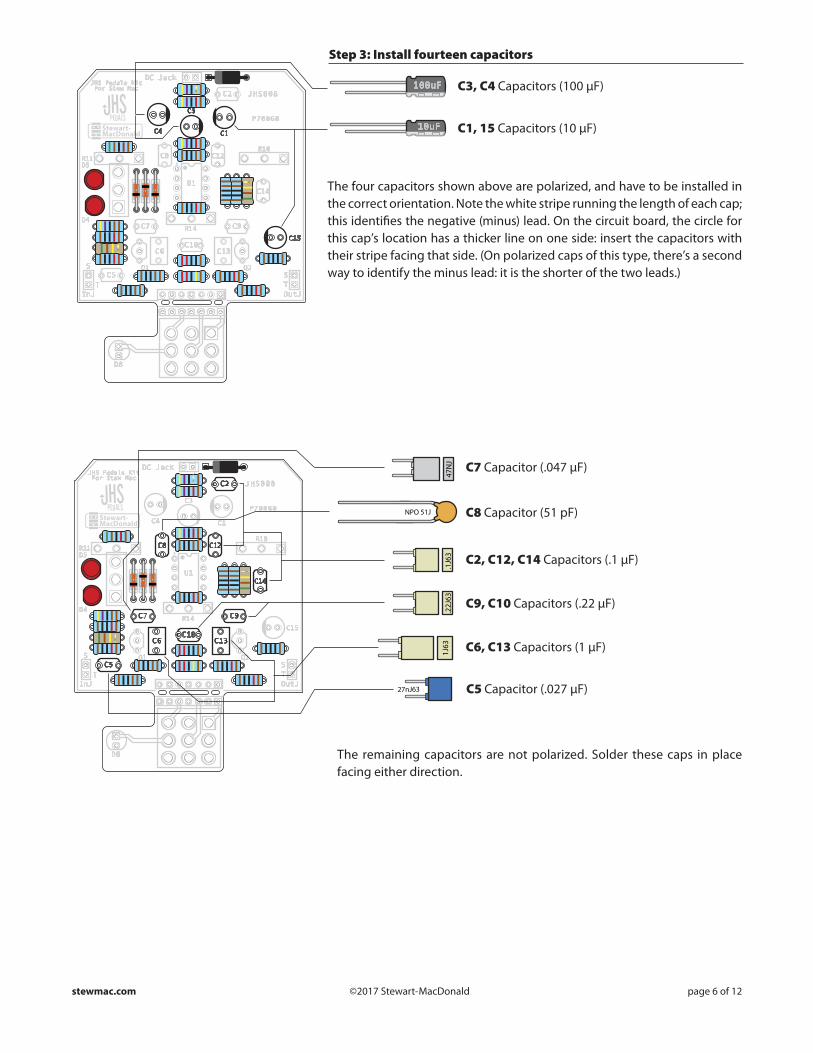
Step 3: Install fourteen capacitors
JHS Pedals KitFor Stew Mac
DC Jack
JHS808
D8
T
SST
R1
R23
R10
R11R18
R14
D5
D4
D1
OutJInJ
P78868
Q1 Q2
C4
C3
C1
C15
C14
C8 C12
C5
C7
C10
C9
C2
R2
R12
R21
R13
R15
R4R5 R20
R22R3
R9R16
R17
R19
R8
R6
R7
D7
D3
D2 U1
C6 C13
C1, 15 Capacitors (10 µF)10uF
100uF C3, C4 Capacitors (100 µF)
JHS Pedals KitFor Stew Mac
DC Jack
JHS808
D8
T
SST
R1
R23
R10
R11R18
R14
D5
D4
D1
OutJInJ
P78868
Q1 Q2
C4
C3
C1
C15
C14
C8 C12
C5
C7
C10
C9
C2
R2
R12
R21
R13
R15
R4R5 R20
R22R3
R9
R16
R17
R19
R8
R6
R7
D7
D3
D2 U1
C6 C13
C2, C12, C14 Capacitors (.1 µF)
.22J
63 C9, C10 Capacitors (.22 µF)
.1J6
3
C8 Capacitor (51 pF)NPO 51J
C7 Capacitor (.047 µF)
47N
J
C6, C13 Capacitors (1 µF)1J63
C5 Capacitor (.027 µF)27nJ63
The four capacitors shown above are polarized, and have to be installed in the correct orientation. Note the white stripe running the length of each cap; this identifies the negative (minus) lead. On the circuit board, the circle for this cap’s location has a thicker line on one side: insert the capacitors with their stripe facing that side. (On polarized caps of this type, there’s a second way to identify the minus lead: it is the shorter of the two leads.)
The remaining capacitors are not polarized. Solder these caps in place facing either direction.

stewmac.com ©2017 Stewart-MacDonald page 7 of 12
Step 5: Install two transistors
Q1 and Q2 are 2n3904 JFET* transistors. They are directional, and need to be installed in a specific orientation. Note that they have a flat side. On the circuit board, their location outlines also have a flat side. Install the transistors to match these outlines.
*JFET: Junction Gate Field-Effect Transistor
Step 4: Install the operational amplifier
The operational amplifier consists of two parts: the op-amp itself (U1), and the socket it plugs into (U1.2).
You’ll solder the socket first, then install the op-amp in the socket.
The op-amp has to be oriented correctly in order to function properly. There are two indicators on the circuit board to guide you in positioning it:
1. The rectangular U1 position marker has a small notch at one end. Align the similar notch in socket U1.2 when installing the socket.
2. The U1 position marker has a dot in one corner. There is a dot molded into the corner of op-amp U1. Align these corners when pressing the op-amp into place.
Solder socket U1.2 to the board. The op-amp U1 then snaps in without solder. This feature allows you to try different op-amps with no soldering.
JHS Pedals KitFor Stew Mac
DC Jack
JHS808
D8
T
SST
R1
R23
R10
R11R18
R14
D5
D4
D1
OutJInJ
P78868
Q1 Q2
C4
C3
C1
C15
C14
C8 C12
C5
C7
C10
C9
C2
R2
R12
R21
R13
R15
R4R5 R20
R22R3
R9R16
R17
R19
R8
R6
R7
D7
D3
D2 U1
C6 C13
.22J63
.22J63.1
J63
.1J6
3
47nJ
U1 Low noise op-amp (4558P 500nA)
U1.2 socket for op-amp
1J63
1J63
.1J63
JHS Pedals KitFor Stew Mac
DC Jack
JHS808
D8
T
SST
R1
R23
R10
R11R18
R14
D5
D4
D1
OutJInJ
P78868
Q1 Q2
C4
C3
C1
C15
C14
C8 C12
C5
C7
C10
C9
C2
R2
R12
R21
R13
R15
R4R5 R20
R22R3
R9
R16
R17
R19
R8
R6
R7
D7
D3
D2 U1
C6 C13
.22J63
.22J63
.1J6
3
.1J6
3
.1J63
47nJ
Q1, Q2 Transistor (2n3904)
1J63
1J63
U1

stewmac.com ©2017 Stewart-MacDonald page 8 of 12
Step 6: Install the mini toggle switch
Step 7: Install the control pots
The three-position mini toggle switch installs on the back of the board, and there is no location marker printed. Solder the switch to the three large eyelets pictured, making sure it’s flat and square to the circuit board.
The switch is not directional, so it works equally well turned in either direction.
The last components to go onto the circuit board are the three control pots. They install on the back of the board. Each pot has three connecting lugs; the illustration in Step 8 shows the three pots in position on the board.
Each pot has an index pin protruding from the case. Break off this pin before installation, so the pot will mount flush against the pedal case. Needle nose pliers work well for removing the pins.
Use the adhesive foam tape to insulate the back of the pot from the soldered leads of the other parts. Solder the pot in place, making sure it sits flat on the back of the board.
On-on solder lug toggle
R18 Volume pot (100 kΩ, linear taper)
Adhesive foam tape (Goes on back of the pots)
R11 Drive pot (500 kΩ, linear taper)
Break o this index pin on all 3 pots.
Adhesive foam tape
R14 Tone pot (5 kΩ, linear taper)

stewmac.com ©2017 Stewart-MacDonald page 9 of 12
Step 9: Install the lead wires, cut the board
Cut the lead wire into six 2" lengths for the input, output, and power jacks. Strip the insulation on the ends and thread them through the front of the board. Solder them on the back of the board.
Now you can cut the switch portion of the board away from the main board. Small wire cutters make quick work of this, and a small saw also works.
Step 8: Install the footswitch, then the ribbon cable
Install the footswitch on the back of the circuit board. The switch lugs will fit in only one of two directions; either orientation works fine. Insert the lugs through the nine eyelets so the switch sits flush, making contact all around.
Solder one lug and let it cool. This holds the switch in place while you solder the remaining lugs.
Next, install the ribbon cable. Insert the cable leads through the front of the board, and solder them in place on the back.
JHS Pedals KitFor Stew Mac
DC Jack
JHS808
D8
T
SST
R1
R23
R10
R11R18
R14
D5
D4
D1
OutJInJ
P78868
C4
C3
C1
C15
C14
C8 C12
C5
C7
C10
C9
C2
R2
R12
R21
R13
R15
R4R5 R20
R22R3
R9
R16
R17
R19
R8
R6
R7
D7
D3
D2 U1
C6 C13
.22J63
.22J63
.1J6
3
.1J6
3
.1J63
47nJ
Q2Q1
U1
B500K B1K Footswitch
Ribbon cable
B100K A500K
B5K
1J63
1J63
Lead wire, cut into six 2" lengths
D8
JHS Pedals KitFor Stew Mac
DC Jack
JHS808
T
SST
R1
R23
R10
R11R18
R14
D5
D4
D1
OutJInJ
P78868
C4
C3
C1
C15
C14
C8 C12
C5
C7
C10
C9
C2
R2
R12
R21
R13
R15
R4R5 R20
R22R3
R9
R16
R17
R19
R8
R6
R7
D7
D3
D2 U1
C6 C13
.22J63
.22J63
.1J6
3
.1J6
3
.1J63
47nJ
Q2Q1
U1
1J63
1J63

stewmac.com ©2017 Stewart-MacDonald page 10 of 12
Step 11: Mount the circuit board in the case
The main circuit board is held in place by the control pots and mini toggle switch.
Install their shafts through the top of the case, and thread flat washers onto them on the outside. Install the mounting nuts so they are good and snug, but take care not to overtighten.
Step 10: Install the LED mounting bezel and the two jacks
LED mounting bezel
Two jacks
Install the plastic mounting bezel for the LED indicator by pressing it in from the outside, through the top of the case. Spread the tabs open inside the case to hold it in place.
Install the input and output jacks on the sides of the case. Keep the lugs facing up so you’ll have easy access when it’s time to solder them.
JHS Pedals KitFor Stew Mac
DC Jack
JHS808
T
SST
R1
R23
R10
R11R18
R14
D5
D4
D1
OutJInJ
P78868
C4
C3
C1
C15
C14
C8 C12
C5
C7
C10
C9
C2
R2
R12
R21
R13
R15
R4R5 R20
R22R3
R9
R16
R17
R19
R8
R6
R7
D7
D3
D2 U1
C6 C13
.22J63
.22J63
.1J6
3
.1J6
3
.1J63
47nJ
Q2Q1
U1
1J63
1J63
D8

stewmac.com ©2017 Stewart-MacDonald page 11 of 12
Step 13: Install the footswitch
Thread one of the nuts onto the footswitch, leaving a 1/8" gap between it and the switch housing. Place the split lock washer on next.
Carefully install the switch so the legs of the diode feed through the D8 holes on the switch circuit board.
Place the flat washer on the switch shaft on the top of the case. As you tighten the remaining nut on the switch, hold the switch circuit board inside the case so that it doesn’t rotate.
Solder the D8 LED and trim the leads.
1/8"
Step 12: Install the LED in the mounting bezel
Like some of the caps and diodes, the D8 LED is polarized and has to be in-stalled in a specific direction. One side of the diode has a flat edge, indicating the negative lead. Another indication is that the negative lead is shorter than the positive. The circle marking the D8 location on the switch circuit board has a corresponding flat to indicate the mounting orientation.
Insert the LED into the bezel. It will be held in place by soldering it to the switch circuit board in Step 13, but for a more secure mount you can run a bead of clear silicone adhesive around the LED and bezel.
JHS Pedals KitFor Stew Mac
DC Jack
JHS808
T
SST
R1
R23
R10
R11R18
R14
D5
D4
D1
OutJInJ
P78868
C4
C3
C1
C15
C14
C8 C12
C5
C7
C10
C9
C2
R2
R12
R21
R13
R15
R4R5 R20
R22R3
R9
R16
R17
R19
R8
R6
R7
D7
D3
D2 U1
C6 C13
.22J63
.22J63
.1J6
3
.1J6
3
.1J63
47nJ
Q2Q1
U1
1J63
1J63
D8
D8 LED (5mm)
JHS Pedals KitFor Stew Mac
DC Jack
JHS808
T
SST
R1
R23
R10
R11R18
R14
D5
D4
D1
OutJInJ
P78868
C4
C3
C1
C15
C14
C8 C12
C5
C7
C10
C9
C2
R2
R12
R21
R13
R15
R4R5 R20
R22R3
R9
R16
R17
R19
R8
R6
R7
D7
D3
D2 U1
C6 C13
.22J63
.22J63
.1J6
3
.1J6
3
.1J63
47nJ
Q2Q1
U1
1J63
1J63
D8

stewmac.com ©2017 Stewart-MacDonald page 12 of 12
Step 15: Wire the input/output jacks
On the circuit board, the input and output jack leads are labeled InJ and OutJ. The leads are also labeled T for tip, and S for sleeve. Looking at a jack, you’ll see that the sleeve lug is attached to the threaded shaft. The tip lug connects to the spring metal piece that contacts the tip of a guitar cord.
Solder these four leads as shown to finish the assembly.
Screw the bottom onto the case and add the control knobs.
Plug in and rock out!
Here’s how to use the JHS808:
Step 14: Install the DC power connector
Insert the DC power connector so the negative lug is facing up, and tighten it in place. The negative lug is the one with the largest metal tab.
Solder the installed leads from the circuit board to the jack. Where they attach to the board, the positive lead is on the the right and the negative is on the left.
JHS Pedals KitFor Stew Mac
DC Jack
JHS808
T
SST
R1
R23
R10
R11R18
R14
D5
D4
D1
OutJInJ
P78868
C4
C3
C1
C15
C14
C8 C12
C5
C7
C10
C9
C2
R2
R12
R21
R13
R15
R4R5 R20
R22R3
R9
R16
R17
R19
R8
R6
R7
D7
D3
D2 U1
C6 C13
.22J63
.22J63
.1J6
3
.1J6
3
.1J63
47nJ
Q2Q1
U1
1J63
1J63
D8
DC power connector NegativePositive
JHS Pedals KitFor Stew Mac
DC Jack
JHS808
T
SST
R1
R23
R10
R11R18
R14
D5
D4
D1
OutJInJ
P78868
C4
C3
C1
C15
C14
C8 C12
C5
C7
C10
C9
C2
R2
R12
R21
R13
R15
R4R5 R20
R22R3
R9
R16
R17
R19
R8
R6
R7
D7
D3
D2 U1
C6 C13
.22J63
.22J63
.1J6
3
.1J6
3
.1J63
47nJ
Q2Q1
U1
1J63
1J63
D8
VolumeOverall output level
ToneAdjusts the top end
DriveDial in moreor less overdrive
3-way gain switchThree tone options:• Up: LED clipping• Middle: Open boost• Down: Silicon clipping
Requires 9V DC center-negative power supply (not included)
Output
Input
FootswitchOn/O LED Indicator
On/O


![[SmartLTE]- APN Modded Fast OM7.5](https://img.dokumen.tips/doc/110x75/55cf984a550346d03396c628/smartlte-apn-modded-fast-om75.jpg)