Embed Size (px)
Citation preview

Electronic Journal of Structural Engineering 14 - 2014
71
1 INTRODUCTION
To prevent shear failure beams are traditionally
reinforced with transverse shear reinforcement. One
alternative to this reinforcement lies is in the use of
steel fiber reinforced concrete (SFRC). The addition
of fibers improves the diagonal tension capacity of
concrete resulting in an increase in shear resistance
which can promote flexural failure and ductility. The
structural use of SFRC typically requires the addi-
tion of high fiber contents which can result in re-
duced workability and difficulty in concrete place-
ment. The combined use of self-consolidating
concrete (SCC) and steel fibers has been proposed as
a solution to this problem and can result in highly
workable SFRC that can allow for the higher fiber
contents required for structural applications.
This paper reports the results of an experimental
study that investigates the performance enhance-
ments that can be gained from the use of highly
workable SFRC in beams tested under four-point
loading. The response of the beams in terms of shear
versus deflection response, crack control and dam-
age tolerance is reported. In the second part of the
paper a model for predicting the shear resistance of
SFRC beams is proposed. Equations proposed in the
literature and by the authors are then used to predict
the shear capacity of the SFRC beams tested in the
experimental program.
2 LITERATURE REVIEW
2.1 Research on shear behavior of SCC beams
There is limited published data in the literature on
the shear behavior of plain SCC beams. Lachemi et
al. (2005) tested a series of 18 normal concrete (NC)
and SCC beams to examine the influence of aggre-
gate size and SCC on the shear behavior of beams.
The authors found that a decrease in aggregate size
from 19 mm to 12 mm reduces the ultimate shear
capacity of reinforced concrete beams. This reduc-
tion in capacity was linked to reduced aggregate in-
terlock when smaller aggregates are used. Similarly
a comparison between the behavior of the NC and
SCC series showed the beams constructed with SCC
had reduced shear capacity when compared to the
companion NC beams. This reduction in capacity
was linked to reductions in aggregate interlock due
to the lesser coarse aggregate content that is typical
Shear Response of SFRC Beams Constructed with SCC and Steel Fibers
Hassan Aoude* & Michael Cohen
Department of Civil Engineering, University of Ottawa, Ottawa, Canada
ABSTRACT: This paper presents the experimental results from eleven slender beams constructed with highly workable SFRC tested under four-point loading. In the study self-consolidating concrete (SCC) was combined with steel fibers to improve workability and concrete placement. The response of the beams in terms of shear versus deflection response, crack control and damage tolerance is reported. The results demonstrate that the combined use of SCC and steel fibers in shear-deficient beams results in significant improvements in shear re-sistance and enhancements in flexural ductility. In the second part of the paper a model is proposed for pre-dicting the shear capacity of SFRC beams. The proposed model and various equations proposed in the litera-ture are used to predict the shear capacity of the beams tested in the experimental program. The results demonstrate the need for developing accurate and reliable equations for predicting the shear capacity of SFRC beams constructed with SCC and steel fibers.
Keywords: Beam-columns, Joints, Concrete, Steel, Finite element analysis

Electronic Journal of Structural Engineering 14 - 2014
72
of SCC. In another recent study, Lin and Chen
(2012) tested 24 beams, which included 8 NC beams
and 16 beams constructed with two types of SCC.
The "Type I" SCC beams contained a greater amount
of coarse aggregate, while the "Type II" SCC beams
had lesser aggregate content. The variables included
shear-span-to-depth ratio (a/d), spacing and strength
of transverse reinforcement. The results demon-
strated that the Type I SCC beams had higher shear
capacity when compared to the companion NC
beams, however in the case of the SCC beams with
reduced aggregate content (Type II), structural per-
formance was inferior with reduced cracking and ul-
timate strengths. The results from these two studies
demonstrate the need for further research on the
shear behavior of SCC beams and the development
of SCC-specific design equations that can modify
existing "traditional concrete" shear-strength re-
quirements in codes.
2.2 Research on shear behavior of SFRC beams
Research over the past three decades has shown
that the provision of steel fibers can be used to en-
hance shear resistance in reinforced concrete beams.
Parra-Montesinos (2006) presented a large database
of SFRC beam test results which included 147
beams from 16 studies. Analysis showed that all
beams in the database having fiber content, Vf ≥
0.5% exhibited shear stress at failure greater than
0.17√f'c [MPa], equivalent to Vc as defined in the
ACI-318 code (ACI, 2011), with beams having Vf ≥
0.75% failing at shear stresses not less than 0.3√f'c
[MPa]. Based on the analysis of the database, it was
recommended that if added in sufficient quantity,
steel fibers can be used as a replacement to mini-
mum shear reinforcement in beams subjected to
shear forces equivalent to 0.5 Vc and Vc.
2.3 Research on shear behavior of SCFRC beams
The addition of steel fibers in traditional concrete
mixes can cause problems in workability and place-
ment, particularly when high fiber contents are used.
The use of self-consolidating concrete (SCC) has
been proposed to reduce these problems and facili-
tate placement (Khayat and Roussell, 2000). Studies
have shown that by utilizing a highly flowable SCC
mix, self-consolidating properties can be maintained
at low or moderate fiber contents, while adequate
workability can be maintained at higher fiber con-
tents (with some loss of self-consolidating proper-
ties). Liao et al. (2006) presented an excellent review
of self-consolidating fiber reinforced concrete
(SCFRC) mix designs studied in the literature.
While there has been several studies focusing on
the development of SCFRC mix designs, there is
limited data in the literature related to the structural
use of SCFRC in beams. Greenough and Nehdi
(2008) performed a study on 13 slender SCFRC
beams having a/d ratios equal to or greater than 3
and having fiber contents ranging from 0.5-1.0%.
The authors noted that SCC is particularly well suit-
ed for fiber addition due to its improved rheological
properties. The authors found that the addition of
steel fibers improves the shear behavior of SCC
slender beams, with results showing that addition of
1.0% fiber content results in a 128% increase in
shear capacity. You et al. (2010) carried out another
investigation on two series of SCC beams reinforced
with steel fibers. The first series included 8 beams
with an a/d ratio of 3.0. Two of the beams were
constructed without stirrups while 6 of the beams
had transverse reinforcement ratios ranging from
0.13%-0.22%. The beams in this second series had
an a/d ratio of 3.2, and transverse reinforcement ratio
ranging from 0.35-0.53%.The results showed that
the addition of steel fibers increases the shear ca-
pacity of SCC beams and that a sufficient quantity of
fibers can alter the failure mode from a brittle shear
collapse into a ductile flexural failure. The authors
of this study also demonstrated that combining steel
fibers with traditional shear reinforcement in the
form of stirrups can produce a positive hybrid effect
and allow for a partial reduction of shear reinforce-
ment without negatively affecting performance. It is
noted that only a moderate fiber content of 0-50
kg/m3 was used in this study, with the authors noting
that 50 kg/m3 may be an upper limit for a fully self-
consolidating fiber-reinforced SCC.
3 RESEARCH NEED
While there is important research in the literature
on the behavior of SFRC beams, there is limited re-
search data on the response of beams constructed
with SCC and steel fibers. Given the recent adoption
of provisions related to use of SFRC in beams in the
ACI 318 code and increased interest in the structural
use of SCFRC and highly-workable SFRC, it is of
importance to enrich the experimental database re-
lated to the shear behavior of beams constructed
with these materials. There is also a need to assess
Electronic Journal of Structural Engineering 14 - 2014
73
the ability of existing models proposed for SFRC to
predict the shear resistance of beams constructed
with SCC and steel fibers.
4 EXPERIMENTAL INVESTIGATION
4.1 Description of test specimens
A total of eleven slender SFRC beams construct-
ed with SCC and steel fibers were tested under four-
point loading. Table 1 summarizes the properties of
the beams tested in the experimental program. The
beams had cross-sectional dimensions of 125 mm x
250 mm, with all specimens having a clear cover of
30 mm, with two ratios of longitudinal reinforce-
ment. Two 15M bars (db=16 mm and As=200 mm2)
were placed at the bottom of the seven beams in the
M15-series, while two 20M bars (db=19.5 mm and
As=300 mm2) were used in the four beams in the
M20-series. No transverse reinforcement was pro-
vided in any of the specimens. All the specimens
were simply supported over a span of 2400 mm and
were subjected to four-point loading with a shear
span of 800 mm from the face of the support (shear
span-to-depth ratio a/d was approximately 3.8), and
a constant moment region of 800 mm. The beams
rested on roller and pin supports while a load trans-
fer beam was used to apply the two point loads.
Table 1. Summary of specimen details
Beams Concrete
Type
Longitudonal
Reinforcement
Fiber
Type
Fiber
content
M15-0.0%
KING
SCC
2 - 15M
(ρ=1.55%)
ZP-305 0.00%
M15-0.5% ZP-305 0.50%
M15-1.0% ZP-305 1.00%
M15-1.5% ZP-305 1.50%
M15-0.5%H BP80/30 0.5%
M15-0.75%H BP80/30 0.75%
M15-1.5%5D 5D 1.50%
M 20-0.75% KING
SCC 2 - 20M
(ρ =2.33%)
ZP-305 0.75%
M 20-1.0% ZP-305 1.00%
M 20-1.0%A Custom
SCC
ZP-305 1.00%
M 20-1.5%A ZP-305 1.50%
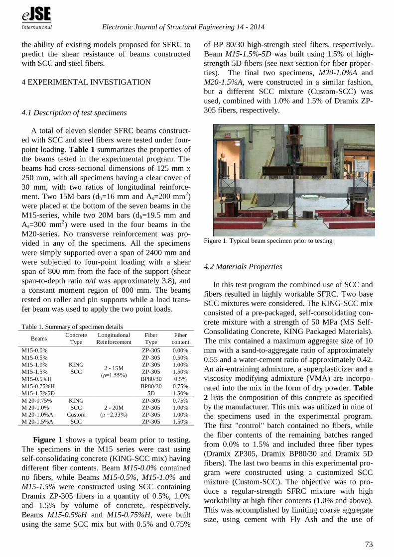
Figure 1 shows a typical beam prior to testing.
The specimens in the M15 series were cast using
self-consolidating concrete (KING-SCC mix) having
different fiber contents. Beam M15-0.0% contained
no fibers, while Beams M15-0.5%, M15-1.0% and
M15-1.5% were constructed using SCC containing
Dramix ZP-305 fibers in a quantity of 0.5%, 1.0%
and 1.5% by volume of concrete, respectively.
Beams M15-0.5%H and M15-0.75%H, were built
using the same SCC mix but with 0.5% and 0.75%
of BP 80/30 high-strength steel fibers, respectively.
Beam M15-1.5%-5D was built using 1.5% of high-
strength 5D fibers (see next section for fiber proper-
ties). The final two specimens, M20-1.0%A and
M20-1.5%A, were constructed in a similar fashion,
but a different SCC mixture (Custom-SCC) was
used, combined with 1.0% and 1.5% of Dramix ZP-
305 fibers, respectively.
Figure 1. Typical beam specimen prior to testing
4.2 Materials Properties
In this test program the combined use of SCC and
fibers resulted in highly workable SFRC. Two base
SCC mixtures were considered. The KING-SCC mix
consisted of a pre-packaged, self-consolidating con-
crete mixture with a strength of 50 MPa (MS Self-
Consolidating Concrete, KING Packaged Materials).
The mix contained a maximum aggregate size of 10
mm with a sand-to-aggregate ratio of approximately
0.55 and a water-cement ratio of approximately 0.42.
An air-entraining admixture, a superplasticizer and a
viscosity modifying admixture (VMA) are incorpo-
rated into the mix in the form of dry powder. Table
2 lists the composition of this concrete as specified
by the manufacturer. This mix was utilized in nine of
the specimens used in the experimental program.
The first "control" batch contained no fibers, while
the fiber contents of the remaining batches ranged
from 0.0% to 1.5% and included three fiber types
(Dramix ZP305, Dramix BP80/30 and Dramix 5D
fibers). The last two beams in this experimental pro-
gram were constructed using a customized SCC
mixture (Custom-SCC). The objective was to pro-
duce a regular-strength SFRC mixture with high
workability at high fiber contents (1.0% and above).
This was accomplished by limiting coarse aggregate
size, using cement with Fly Ash and the use of

Electronic Journal of Structural Engineering 14 - 2014
74
chemical admixtures. The mixture contained Type
10 cement and class C fly ash. Coarse aggregate size
was limited to 12 mm while silica sand was used as
fine aggregate. The mix incorporated hooked-end
steel fibers at fiber contents of 1.0% to 1.5%. A su-
perplastizer (ADVA CAST 575) and viscosity modi-
fying admixture (V-MAR 3) were used in order to
improve workability and prevent segregation. Table
2 summarizes the final mix proportions which were
determined using a series of trial batches and based
on a review of mixtures proposed in the literature
(Liao et al. 2006).
Table 2. Mix design properties
Component KING-SCC Custom-SCC
Cement 500 (kg/m3) 473 kg/m
3)
Fly Ash --- 238 (kg/m3)
WC ratio 0.42 0.33
Coarse Agg. 765 (kg/m3) 439 (kg/m
3)
Fine Agg. 915 (kg/m3) 806 (kg/m
3)
Mass Density 2300 (kg/m3) 2400 (kg/m
3)
Superplastizer In form of dry
powder
292 (ml/100 kg)*
VMA 52 (ml/100 kg)**
Steel Fibers 0.5-1.5 (%) 1.0-1.5 (%)
* ADVA CAST 575, in ml/100 kg of cementitious materials
** V-MAR 3, in ml/100 kg of cementitious materials
Three types of steel fibers were used in this ex-
perimental program (see Figure 2). All fibers are
manufactured by Bekaert. The ZP305 hooked-end
fibers have 30 mm length, aspect-ratio (Lf/df) of 55
and are made of normal strength steel wire with a
tensile strength of 1100 MPa. The hooked-end
BP80/30 fibers have 30 mm length, aspect-ratio of
80 and a higher tensile strength of approximately
2300 MPa. Finally, the 5D fibers have length of 60
mm, aspect-ratio of 65, tensile strength of 2300
MPa and have a more optimized hook shape (two
bends in the end hooks to increase pullout strength).
The 15M bars in the first series of beams had a
yield strength (fy) of 441 MPa, while the 20M bars
which were utilized to reinforce the remaining
beams had a yield strength of 474 MPa.
The workability of the concrete mixtures was
measured by performing slump flow tests on each
batch of SCC and SFRC. Table 3 summarizes the
average results from the slump flow test. As noted
previously the goal of combining SCC and steel fi-
bers in this study was to produce highly workable
SFRC. As such, self-consolidating properties were
expected to be lost at the higher fiber contents.
Nonetheless, all mixtures remained sufficiently
workable. During casting of the specimens con-
structed with the KING-SCC mix and normal-
strength fibers, no vibration was required at a fiber
content of 0.5% and 1.0%, while slight vibration was
required when casting the specimens with 1.5% fi-
bers. The use of 0.75% of high-strength fibers signif-
icantly reduced workability owing to the higher as-
pect ratio of this fiber, and required significant
vibration during casting. A sufficiently workable
mix was obtained when using 1.5% of the 5D fibers
and only slight vibration was required during cast-
ing, although some slight segregation was observed
during visual inspection after the slump flow test. In
terms of the custom-SCC mix, the SFRC showed
highly workability allowing for easy concrete place-
ment during construction of the beams.
Figure 2. Hooked-end steel fibers considered in this study:
(a) ZP305; (b) BP80/30; and (c) 5D fibers.
A series of lab cured cylinders and flexural beams
were prepared during the mixing of the concrete
(three cylinders and one flexural beam for each
batch). The specimens were cured with burlap and
covered with plastic sheets for seven days, and were
then demolded and air-cured in the laboratory until
testing. The control samples were tested on the day
of the corresponding beam tests (the age of the spec-
imens on the day of testing varied between 95 and 97
days, with the exception of the beam with the 5D fi-
bers which had an age of 45 days at the day of test-
ing). Compressive strengths were obtained by testing
standard cylinders having a diameter of 100 mm and
a height of 200 mm (average strengths at the day of
testing, fc are summarized in Table 3). In addition,
bending tests performed according to the ASTM
C1609 Standard (ASTM, 2007) were used to exam-
ine toughness. The tests were conducted on samples
that were 100 mm by 100 mm by 400 mm in size
which were loaded over a span of 300 mm . Average
modulus of rupture values, fr are summarized in Ta-
ble 3 and toughness parameters are reported in Ta-
ble 4 for the various SCC and SFRC mixtures.

Electronic Journal of Structural Engineering 14 - 2014
75
Table 3. Average concrete properties: compressive strength, modulus of rupture, slump flow, and sample slump flow photos
Mix SCC-0.0% SCC-0.5% SCC-0.75% SCC-1.0% SCC-1.5%
fc , MPa 51.9 59.4 49.7 51.5 55.8
fr , MPa 6.0 7.0 --* 6.7 7.7
Slump, mm 600 530 520 485 440
Sample
Slump Photo
Mix SCC-0.5H% SCC-0.75H% SCC-1.0%A SCC-1.5%A SCC-1.5%5D
fc , MPa 49.6 46.0 54.5 50.5 52.8
fr , MPa 6.5 5.8 7.3 8.5 --*
Slump, mm 440 410 440 400 450
Sample
Slump Photo
* No flexural beams were tested for the mixtures with 0.75% ZP305 fibers and 1.5% 5D fibers
Table 4. Results from flexural toughness tests and comparison to ACI performance requirements
Mixture
Name ASTM C1609 Meets ACI requirements ?
fr,ACI f1 fp f300 f600 f150 90% f1 75% f1 T150 vf ≥0.75% f300 ≥ 90%f1 f150 ≥ 75%f1
M15-0.0% 5.04 5.93 5.93 - - - 5.34 4.45 -
M15-0.5% 5.39 7.02 7.02 2.91 5.06 1.68 6.32 5.26 23.40
M15-1.0% 5.02 6.72 6.72 3.95 5.26 2.59 6.05 5.04 27.23
M15-1.5% 5.23 6.11 7.70 6.38 0.15 4.67 5.49 4.58 40.44
M15-0.5%H 4.93 6.46 6.46 6.05 5.24 5.57 5.80 4.85 37.68
M15-0.75%H 4.75 5.58 5.72 5.00 5.72 4.20 5.02 4.19 32.18
M 20-1.0%A 4.97 5.77 7.25 7.54 6.66 5.92 5.19 4.33 44.47
M 20-1.5%A 5.17 4.91 8.45 8.00 8.21 6.14 4.41 3.88 48.43
Load-deflection responses are presented in Fig-
ure 3 (it is noted that no flexural beam data is avail-
able for the specimens with 0.75% ZP305 fibers and
1.5% 5D fibers). As expected increasing fiber con-
tent results in improved post-cracking resistance and
toughness. For the KING-SCC mix, examination of
the results in Table 4 shows that the T150 toughness
parameter, which corresponds to the area under the
load-deflection curves from 0 to L/150, increased by
49% for the mix with 1.5% ZP305 fibers when com-
paring to the mix with 1% ZP305 fibers. Similarly,
the use of 0.5% high-strength BP80/30 fibers result-
ed in a 61% increase in toughness when comparing
to the mix with 0.5% normal-strength ZP305 fibers.
When comparing to the KING-SCC mix, the use of
1% ZP305 fibers in the Custom-SCC mix showed a
63% increase in toughness. The ACI-318 code re-
cently introduced provisions permitting the use of
SFRC in flexural members (ACI, 2011). In order to
qualify as an alternative to minimum shear rein-
forcement in beams material, dimensional and load-
ing limits must be met. At the material level, the
SFRC must have a minimum fiber content of 60
kg/m3 and meet minimum performance require-
ments. The residual strength obtained from the
ASTM C1609 test at midspan deflections of L/300
and L/150 must be greater or equal to 90% and 75%
of the first-peak strength, respectively (where the
first-peak strength, fp, is obtained from a flexural test
but not lesser than the value specified in Eq. 9-10 of
the ACI 318 code).
0
5
10
15
20
25
30
35
0 1 2 3 4
Load (
kN
)
Net Deflection (mm)
SCC 0.0%
SCC 0.5%
SCC 1.0%
SCC 1.5%
(a) 0%, 0.5%, 1%, 1.5%;
0
5
10
15
20
25
30
35
0 1 2 3 4
Load (
kN
)
Net Deflection (mm)
SCC 0.5%H
SCC-0.75%H
SCC 1.0%A
SCC 1.5%A
(b) 0.5%H, 0.75%H, 1%A, 1.5%A
Figure 3. Sample flexural beam load-deflection responses.

Electronic Journal of Structural Engineering 14 - 2014
76
Examining the residual strength values in Table 4 it
is seen that for the KING-SCC mix, the performance
requirements specified by the code are met for the
mixtures containing 1.5% normal-strength fibers and
0.75% high-strength fibers, whereas the require-
ments are not met for the mixtures with 0.5% or 1%
fibers. For the Custom-SCC mix, the ACI require-
ments are satisfied at fiber contents of 1.0% & 1.5%.
5 RESULTS AND DISCUSSION
5.1 M15 Series-Effect of fiber content
To recall, the seven beams in the M15-KING se-
ries had identical cross-sectional properties and were
cast using a traditional SCC mix. The series included
one control beam (Beam M15-0.0%) and six beams
having varying fiber contents (ranging from 0.5% to
1.5%) and fiber types. Table 5 and Figure 4 com-
pare the shear and deflections values (at maximum
and at failure) and the load-deflection responses of
the various beams tested in this series.
In terms of shear resistance, as has been reported
for traditional SFRC beams, one can see that the ad-
dition of steel fibers in SFRC beams constructed
with SCC and steel fibers leads to improvements in
shear capacity. In addition, as the fiber content is in-
creased so does the relative increase in shear
strength. For example, as shown in Table 5 and
Figure 4(a), the addition of 0.5% fibers in Beam
M15-0.5% increased the shear capacity of the beam
by 47% when comparing to the strength of the con-
trol beam. A further increase in fiber content to 1.0%
has led to 63% improvement in shear strength when
compared to the control beam. The use of 1.5% fi-
bers did not lead to a further increase in capacity
when compared to the companion beam with 1.0%
fibers. It is noted that these last two beams failed in
flexure and the result shows that addition of steel fi-
bers does not have a significant influence in increas-
ing moment capacity in beams failing in flexure.
5.2 M15 Series-Effect of fiber type
In addition to the above specimens, two of the
beams in the M15-series were constructed with high-
strength BP80/30 steel fibers. A comparison of the
results from Table 5 and Figure 4(b) shows the
beneficial impact of using high-strength fibers. Be-
sides the improvement in shear capacity, the use of
high-strength fibers has contributed to an enhanced
post-peak response and ductility. Just as in the case
of the normal strength fibers, the use of high-
strength fibers was shown to improve ultimate shear
capacity and member response. When compared to
the control beam, increases in strength of 54% and
63% for Beams M15-0.5%H and M15-0.75%H were
observed. The response of Beam M15-0.5%H shows
that the use of high-strength fibers allowed the beam
to sustain significant deflections before failure when
compared to the control specimen. Similarly, alt-
hough both Beams M15-0.5% and M15-0.5%H
failed in shear at similar failure loads, a comparison
between the deflections at failure (see Table 5) and
the member responses (see Figure 4(b)) demon-
strates an improved level of ductility for the beam
reinforced with high-strength fibers (with Beam
M15-0.5%H experiencing 200% increase in deflec-
tions before failure). The results also show that an
increase in high-strength fiber content to 0.75% re-
sulted in a further increase in strength and was suffi-
cient to produce a ductile flexural failure in Beam
M15-0.75%H. As noted previously, the use of high-
strength fibers resulted in reduced workability and
some reduction in compressive strength (possibly
due to increased entrapped air). Nonetheless, it is
noted that the structural response of Beam M15-
0.75%H is very similar to the response of Beam
M15-1.0% in terms of flexural ductility. The results
from specimens M15-0.5%H and M15-0.75%H indi-
cate the potential benefits from the use of higher
strength steel fibers in beams, however further re-
search is recommended. Owing to the higher aspect-
ratio of the BP80/30, careful SCC mix proportioning
is recommended in order to ensure adequate worka-
bility and reliable structural performance. Figure
4(c) shows the response of Beams M15-1.5% and
M15-1.5%5D. Both beams failed in flexure, however
the use of the 5D fibers, which have optimized
strength and anchorage properties, resulted in an in-
crease in beam flexural capacity.
5.3 M20 Series-Effect of fiber content
Beams M20-0.75% and M20-1.0% were con-
structed with a traditional SCC mix, normal strength
hooked-end steel fibers and fiber contents of 0.75%
and 1.0% by volume of concrete, respectively. It is
noted that no control beam was tested in the M20-
series. To allow for a comparison of shear capacities,
the nominal shear strength of a reinforced concrete
beam having identical properties but without fibers

Electronic Journal of Structural Engineering 14 - 2014
77
was predicted using the general shear design method
of the CSA A23.3-04 Standard (CSA, 2004); assum-
ing compressive strength, fc of 50 MPa and yield
strength, fy of 474 MPa, a nominal capacity of 34
kN was predicated. Table 5 compares the maximum
shear capacities of the two SFRC beams with the
calculated nominal capacity and indicates a relative
increase in resistance due to addition of steel fibers.
The results also show that increasing the fiber con-
tent from 0.75% to 1.0% is accompanied by a rela-
tive increase in shear resistance. As shown in Figure
5, despite the enhancement in shear capacity, the
failure pattern for both beams in this series was brit-
tle and the beams failed in shear with a sudden loss
in load-carrying capacity at failure.
5.4 M20 Series-Effect of longitudinal reinforcement
The beams discussed in the previous section were
reinforced with two 20M bars, whereas all other
properties including concrete type remained un-
changed from the M15 test series. A comparison of
the responses of Beams M15-1.0% and M20-1.0% in
Figures 4(a) & 5 show that while 1.0% fibers was
sufficient to transform the brittle shear response in
the M15 series beam, the use of 1.0% fibers in the
beam with 20M reinforcement was not sufficient to
avoid a brittle shear failure. The reason returns to the
higher flexural capacity in the beams with larger re-
inforcement ratio. That is to say that the additional
shear capacity provided by 1.0% steel fibers was not
sufficient to “make up” the shear required to reach
the beam’s flexural capacity in the beam with larger
reinforcement ratio. The result puts into evidence the
importance of developing accurate equations for
predicting the shear resistance of SFRC beams.
5.5 M20 Series-Effect of concrete type
In addition to the two beams constructed with tra-
ditional SCC, the M20 series also included two other
beams constructed with a customized concrete mix-
ture (SCC-Custom Mix). In comparing the results in
Table 5 Beams M20-1.0%A and M20-1.5%A have
shown a 74% and 82% higher shear capacity respec-
tively when compared to the expected nominal shear
strength capacity for a beam without fibers. A com-
parison of the responses of Beam M20-1.0% from
the M20-KING series and Beam M20-1.0%A allows
for an investigation into the effect of concrete type
on response. Both beams were reinforced with 1.0%
normal-strength hooked-end fibers and had identical
properties with the exception of concrete mix type.
In comparing the results in Figure 5 one can see that
while the capacities of the beams was similar and
failure in both cases was in shear, the beam con-
structed with the customized SCC mix (Beam M20-
1.0%A) showed an improved level of ductility when
compared to the companion beam. This may be
linked to the improved concrete tensile properties of
this SFRC mixture and the fact that yielding was ini-
tiated in the longitudinal reinforcement before the
brittle failure in this specimen. As shown in Figure
5, while 1.0% fibers was not sufficient to prevent a
brittle shear failure in the previous two beams in this
series, the use of 1.5% fibers in Beam M20-1.5%A
was adequate to transform the failure into a ductile
flexural response.
0
10
20
30
40
50
60
70
0 10 20 30 40 50 60 70
Sh
ear
(kN
)
Mid-span deflection (mm)
M15-0.0%
M15-0.5%
M15-1.0%
M15-1.5%
(a) 0%, 0.5%, 1%, 1.5%
0
10
20
30
40
50
60
70
0 10 20 30 40 50 60 70
Sh
ear
(kN
)
Mid-span deflection (mm)
M15-0.5%
M15-0.5% H
M15-0.75% H
(b) 0.5%, 0.5%H, 0.75%H
0
10
20
30
40
50
60
70
0 10 20 30 40 50 60 70
Sh
ear
(kN
)
Mid-span deflection (mm)
M15-1.5%
M15-1.5%(5D)
(c) 1.5%, 1.5%(5D)
Figure 4. Results for the M15 series

Electronic Journal of Structural Engineering 14 - 2014
78
0
10
20
30
40
50
60
70
0 10 20 30 40 50 60 70
Sh
ear
(kN
)
Mid-span deflection (mm)
M20-0.75%
M20-1.0%
M20-1.0% A
M20-1.5% A
Figure 5. Results for the M20 series: 0.75%, 1%, 1%A, 1.5%A.
Table 5. Results for beams tested in the experimental program
Beam
specimen Max Load (kN)
Increase in
Shear (%) Deflection (mm)
Total
Load
Shear
Load
at
Peak
at
Failure
M15-0.0% 60 30 --- 11 11
M15-0.5% 87 43 47% 18 18
M15-1.0% 96 48* ≥ 63% 41 55
M15-1.5% 93 46* ≥ 60% 24 71
M15-0.5%H 90 45 54% 40 40
M15-0.75%H 95 48* ≥ 63% 37 51
M15-1.5% 5D 104 52* ≥ 73% 33 54
M 20-0.75% 88 44 30%** 15 15
M 20-1.0% 116 58 69%** 20 20
M 20-1.0%A 118 59 74%** 31 31
M 20-1.5%A* 124 62* ≥ 82%** 39 57
*Beam failed in flexure
** comparison to the nominal shear strength of a beam without fi-
bers as predicted using the CSA A23.3 general shear design method
5.6 Effect on crack widths
As expected the utilization of steel fibers in the
SFRC beams had an important influence on shear
and flexural crack widths (plots for the growth of
crack widths for a sample of the beams are shown in
Figures 6(a) and 6(b)). For the M15-series, the con-
trol specimen (Beam M15-0.0%) as well as the
beams with 0.5% normal strength and high-strength
fibers (Beams M15-0.5% and M15-0.5%H, respec-
tively) failed suddenly in shear. For the control beam
the failure was accompanied with very little warning
of the eminent shear failure with the crack width just
before sudden failure remaining at 0.2 mm. Beam
M15-0.5% which also failed under shear, was able to
resist a slightly larger crack width of approximately
0.4 mm before failure. The use of high-strength BP
80/30 fibers in Beam M15-0.5%H permitted this
specimen to show very large critical shear crack
width (exceeding 1.0 mm) prior to failure (see Fig-
ure 7). This enhancement is linked to the higher ten-
sile strength and increased aspect-ratio of this fiber
type, which results in enhanced pullout behavior al-
lowing the BP 80/30 fibers to more effectively
bridge the critical diagonal shear crack and the fact
that some flexural yielding had initiated in this beam
prior to the brittle shear failure. Beams M15-1.0%
and M15-1.5% of the M15-series failed in flexure. A
comparison of the flexure crack widths for these
beams demonstrates that increasing the fiber content
from 1.0% to 1.5% results in a better control of flex-
ural crack widths at equivalent load stages. The re-
sults also show that using 0.75% high-strength
BP80/30 fibers results in a better control of crack
widths when compared to the companion specimens
with 1.0% and 1.5% normal strength fibers. In addi-
tion to the above observations, examination of the
diagonal shear cracks in the SFRC beams reveals
that the fibers pullout rather than fraction across the
cracking plane when shear failure occurs. An inter-
esting observation is that the hooked-end fibers de-
form and straighten during pullout (see Figure 7).
0
10
20
30
40
50
60
70
0 0.1 0.2 0.3 0.4 0.5 0.6 0.7 0.8 0.9 1
Load (
kN
)
Crack width (mm)
M15-0.0%
M15-0.5%
M15-1.5%
M15-0.5%H
M15-0.75%H
(a) Shear crack-widths as a function of shear load
0
10
20
30
40
50
60
70
0 0.1 0.2 0.3 0.4 0.5 0.6 0.7 0.8 0.9 1
Load (
kN
)
Crack width (mm)
M15-0.0%
M15-1.0%
M15-1.5%
M15-0.75%H
(b) Flexural crack-widths as a function of total load
Figure 6. Effect of fibers on crack widths
Figure 7. Other observations: (left) Control of shear crack up to
1 mm in width prior to failure in beam M15-0.5%H; (right) observed straightening of hooked-end fibers during pullout.
Electronic Journal of Structural Engineering 14 - 2014
79
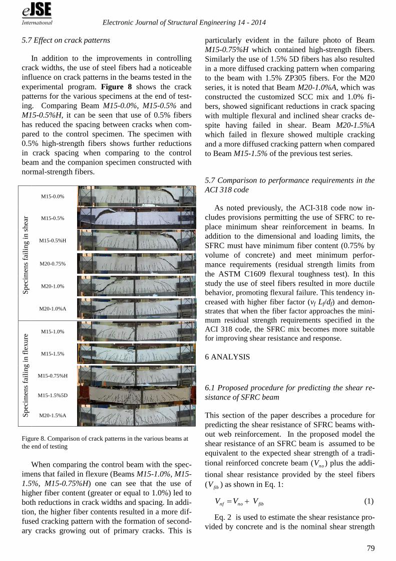
5.7 Effect on crack patterns
In addition to the improvements in controlling
crack widths, the use of steel fibers had a noticeable
influence on crack patterns in the beams tested in the
experimental program. Figure 8 shows the crack
patterns for the various specimens at the end of test-
ing. Comparing Beam M15-0.0%, M15-0.5% and
M15-0.5%H, it can be seen that use of 0.5% fibers
has reduced the spacing between cracks when com-
pared to the control specimen. The specimen with
0.5% high-strength fibers shows further reductions
in crack spacing when comparing to the control
beam and the companion specimen constructed with
normal-strength fibers.
Spec
imen
s fa
ilin
g i
n s
hea
r
M15-0.0%
M15-0.5%
M15-0.5%H
M20-0.75%
M20-1.0%
M20-1.0%A
Sp
ecim
ens
fail
ing i
n f
lexure
M15-1.0%
M15-1.5%
M15-0.75%H
M15-1.5%5D
M20-1.5%A
Figure 8. Comparison of crack patterns in the various beams at
the end of testing
When comparing the control beam with the spec-
imens that failed in flexure (Beams M15-1.0%, M15-
1.5%, M15-0.75%H) one can see that the use of
higher fiber content (greater or equal to 1.0%) led to
both reductions in crack widths and spacing. In addi-
tion, the higher fiber contents resulted in a more dif-
fused cracking pattern with the formation of second-
ary cracks growing out of primary cracks. This is
particularly evident in the failure photo of Beam
M15-0.75%H which contained high-strength fibers.
Similarly the use of 1.5% 5D fibers has also resulted
in a more diffused cracking pattern when comparing
to the beam with 1.5% ZP305 fibers. For the M20
series, it is noted that Beam M20-1.0%A, which was
constructed the customized SCC mix and 1.0% fi-
bers, showed significant reductions in crack spacing
with multiple flexural and inclined shear cracks de-
spite having failed in shear. Beam M20-1.5%A
which failed in flexure showed multiple cracking
and a more diffused cracking pattern when compared
to Beam M15-1.5% of the previous test series.
5.7 Comparison to performance requirements in the
ACI 318 code
As noted previously, the ACI-318 code now in-
cludes provisions permitting the use of SFRC to re-
place minimum shear reinforcement in beams. In
addition to the dimensional and loading limits, the
SFRC must have minimum fiber content (0.75% by
volume of concrete) and meet minimum perfor-
mance requirements (residual strength limits from
the ASTM C1609 flexural toughness test). In this
study the use of steel fibers resulted in more ductile
behavior, promoting flexural failure. This tendency in-
creased with higher fiber factor (vf Lf/df) and demon-
strates that when the fiber factor approaches the mini-
mum residual strength requirements specified in the
ACI 318 code, the SFRC mix becomes more suitable
for improving shear resistance and response.
6 ANALYSIS
6.1 Proposed procedure for predicting the shear re-
sistance of SFRC beam
This section of the paper describes a procedure for
predicting the shear resistance of SFRC beams with-
out web reinforcement. In the proposed model the
shear resistance of an SFRC beam is assumed to be
equivalent to the expected shear strength of a tradi-
tional reinforced concrete beam ( noV ) plus the addi-
tional shear resistance provided by the steel fibers
( fibV ) as shown in Eq. 1:
fibnonf VVV (1)
Eq. 2 is used to estimate the shear resistance pro-
vided by concrete and is the nominal shear strength

Electronic Journal of Structural Engineering 14 - 2014
80
equation of the general shear design method of the
CSA A23.3-04 Standard (CSA, 2004):
vwcno dbfλV (2)
In the equation, wb and vd represent the beam
width and effective shear depth, is a factor that
takes into account the use of low-density concrete,
and is a parameter that accounts for the ability of
the concrete to transmit tensile stresses between the
cracks. The angle is the angle of inclination of the
diagonal compressive stresses to the longitudinal ax-
is of the member. In the general design method both
these parameters are a function of the longitudinal
strain at mid-depth of the cross-section, x , as shown
in Eq. 3 and Eq. 4. The crack spacing parameter, zes
is a function of the maximum aggregate size.
zex s
1000
1300
15001
40.0
(3)
297000x (4)
The longitudinal strain at mid-depth of the cross
section, x is computed using Eq. 5 for the case of
moment and shear:
ss
v
xAE
Vd
M
2
(5)
In the above expression the shear, V , corresponds
to the expected shear resistance of the beam without
fibers. The moment, M , represents the correspond-
ing moment at the critical section in the beam (for
the beams in this analysis the critical section is taken
at a distance vd from the loading point). sA and sE
are the cross-sectional area and modulus of elasticity
of the longitudinal tension steel, respectively.
The second component of Eq. 1 accounts for the
shear strength contribution of the fibers as they
pullout across an inclined shear crack (see Figure 9)
and is predicted using Eq. 6:
cot8.072.1 vwpfibfib dbFNa
dV (6)
The effective number of fibers per unit area, fibN ,
for fibers randomly oriented in three dimensions can
be calculated using Eq. 7:
l
f
f
fibA
vN (7)
Where fA is the cross-sectional area of the fiber,
and where fv is the volume fraction of fibers in the
matrix. The orientation factor, , is used to account
for the random orientation of the fibers crossing any
arbitrary cracking plane and is taken as 3/8 (Foster,
2001). The length factor l is used to account for
the variability in the fiber embedment length across
the cracking plane and is taken as 0.5 (Aoude, 2008).
Ө
Ө
Fpullout
Va
T Vd
d dv = 0.9 d
V
C Vcz
Figure 9. Contribution of fibers to shear resistance with
pullout across inclined shear crack
Anchorage properties play an important role in
improving the pullout resistance of steel fibers. In
the case of hooked-end fibers Alwan et al.(1999)
showed that the mechanical contribution of the hook
is a function of the cold work needed to straighten
the fiber as it is being pulled out from the matrix. It
was also demonstrated that this contribution is ap-
proximately independent of matrix type and fiber
embedment length. In the case of hooked-end fibers,
the pullout strength can therefore be estimated by
adding a hook contribution ( hookP ) to the load
needed to cause fiber debonding as shown in Eq. 8:
hook
f
fbondp PL
dF
2 (8)
In the above expression, the parameters fd and
fL represent fiber diameter and fiber length (taken as
the length of the straight portion of the fiber). The
bond-shear strength, bond , is a function of the con-
crete matrix strength and is determined using Eq. 9:
35.1)(11.1 ctbond f (9)
where ctf is the tensile strength of concrete taken
as '33.0 cct ff . Table 6 shows data for average
bond shear stress determined from single fiber pull-
out tests for a range of concrete matrix strengths as
Electronic Journal of Structural Engineering 14 - 2014
81
reported by Grünewald (2004). Figure 10 shows that
Eq. 9 provides a good fit to the data in Table 6.
Table 6. Range of bond shear strength values Matrix
strength class
Concrete strength range
cf (MPa)
Bond shear stress
bond (MPa)
Normal strength 50 2.0-3.0
Medium strength 50 & 70 3.4-4.5
High strength 70 5.0-6.0
τbond = 1.11fct1.35
0.0
1.0
2.0
3.0
4.0
5.0
6.0
7.0
0.0 1.0 2.0 3.0 4.0
Bo
nd
sh
ear
stre
ss, τ
bond
(MPa
)
Concrete tensile strength, fct (MPa)
Data from Table 6
Figure 10. Bond shear strength according to Eq. 9
For a typical hooked-end fiber, the hook contribu-
tion to pullout can be estimated using Eq. 10:
6
2dπ
18045cos
05.32
ffyoohook fP
(10)
where fyf is the fiber yield strength (in psi) and
fd is the fiber diameter (in inches).
For the case of crimped fibers the pullout strength
is determined using Eq. 1, where the load needed to
cause the debonding of a smooth fiber is scaled us-
ing a form factor, c , that accounts for improved
pullout resistance in crimped fibers. In the current
study the form factor is estimated to be 2.8 based on
regression analysis of data from single fiber pullout
tests on crimped fibers (Cohen, 2012):
2
f
fbondcp
LdF (11)
The pullout strength in Eq. 8 and 11, pF , is valid
for the situation of pure tensile pullout. However in a
beam, the fibers will resist tension along the diago-
nal cracks while undergoing a shear deformation
(see Figure 11). To account for reduced pullout effi-
ciency in the situation of combined tension and
shear, an empirically determined pullout modifica-
tion factor of 0.8 is applied to Eq. 6 to reduce the
pullout resistance of the fibers. The factor was de-
termined based on a regression analysis of a large
database of SFRC beam test results (Aoude, 2008).
Figure 11. Reduced pullout resistance in the case of com-
bined tension and shear.
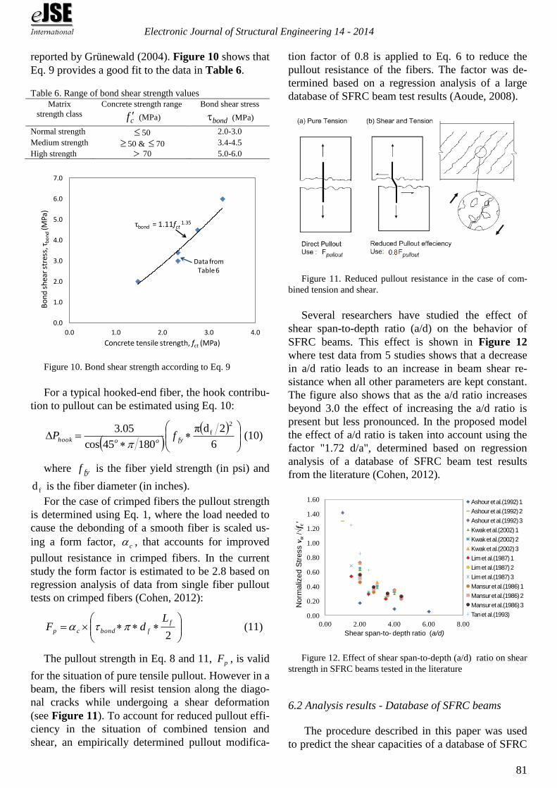
Several researchers have studied the effect of
shear span-to-depth ratio (a/d) on the behavior of
SFRC beams. This effect is shown in Figure 12
where test data from 5 studies shows that a decrease
in a/d ratio leads to an increase in beam shear re-
sistance when all other parameters are kept constant.
The figure also shows that as the a/d ratio increases
beyond 3.0 the effect of increasing the a/d ratio is
present but less pronounced. In the proposed model
the effect of a/d ratio is taken into account using the
factor "1.72 d/a", determined based on regression
analysis of a database of SFRC beam test results
from the literature (Cohen, 2012).
0.00
0.20
0.40
0.60
0.80
1.00
1.20
1.40
1.60
0.00 2.00 4.00 6.00 8.00
No
rmaliz
ed S
tress v
u/√
f c'
Shear span-to- depth ratio (a/d)
Ashour et al.(1992) 1
Ashour et al.(1992) 2
Ashour et al.(1992) 3
Kwak et al.(2002) 1
Kwak et al.(2002) 2
Kwak et al.(2002) 3
Lim et al.(1987) 1
Lim et al.(1987) 2
Lim et al.(1987) 3
Mansur et al.(1986) 1
Mansur et al.(1986) 2
Mansur et al.(1986) 3
Tan et al.(1993)
Figure 12. Effect of shear span-to-depth (a/d) ratio on shear
strength in SFRC beams tested in the literature
6.2 Analysis results - Database of SFRC beams
The procedure described in this paper was used
to predict the shear capacities of a database of SFRC
Electronic Journal of Structural Engineering 14 - 2014
82
beams tested by other researchers. The database in-
cludes results from 129 SFRC beams having effec-
tive depths (d) ranging from 180-570 mm, shear-
span to depth ratio (a/d) ranging from 2.4-6.0, com-
pressive strength ( 'cf ) between 18-104 MPa, longi-
tudinal reinforcement ratios (ρ) ranging from 0.4%-
5%, fiber volume fractions (vf) ranging from 0.25%-
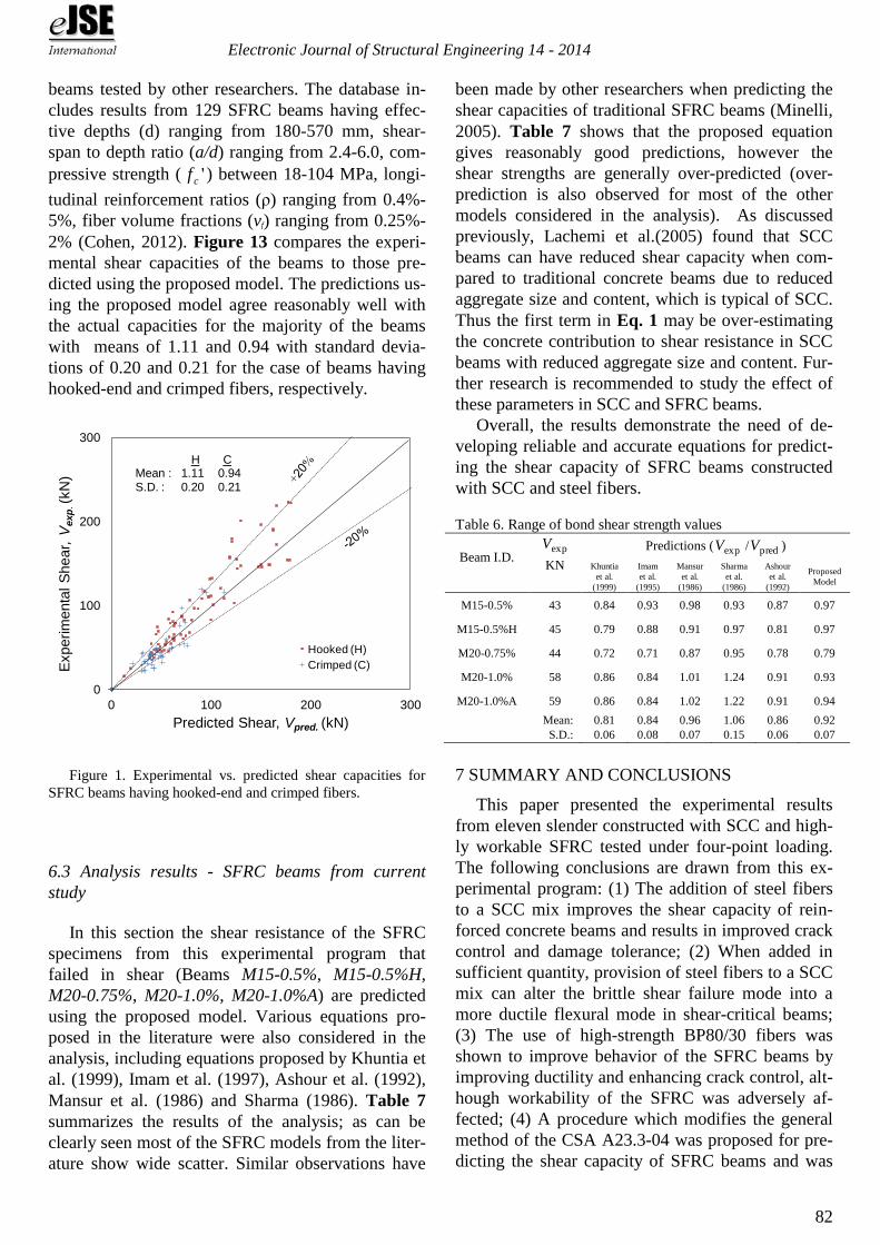
2% (Cohen, 2012). Figure 13 compares the experi-
mental shear capacities of the beams to those pre-
dicted using the proposed model. The predictions us-
ing the proposed model agree reasonably well with
the actual capacities for the majority of the beams
with means of 1.11 and 0.94 with standard devia-
tions of 0.20 and 0.21 for the case of beams having
hooked-end and crimped fibers, respectively.
0
100
200
300
0 100 200 300
Experim
enta
l S
hear,
Vexp
. (k
N)
Predicted Shear, Vpred. (kN)
Hooked (H)
Crimped (C)
H CMean : 1.11 0.94S.D. : 0.20 0.21
Figure 1. Experimental vs. predicted shear capacities for
SFRC beams having hooked-end and crimped fibers.
6.3 Analysis results - SFRC beams from current
study
In this section the shear resistance of the SFRC
specimens from this experimental program that
failed in shear (Beams M15-0.5%, M15-0.5%H,
M20-0.75%, M20-1.0%, M20-1.0%A) are predicted
using the proposed model. Various equations pro-
posed in the literature were also considered in the
analysis, including equations proposed by Khuntia et
al. (1999), Imam et al. (1997), Ashour et al. (1992),
Mansur et al. (1986) and Sharma (1986). Table 7
summarizes the results of the analysis; as can be
clearly seen most of the SFRC models from the liter-
ature show wide scatter. Similar observations have
been made by other researchers when predicting the
shear capacities of traditional SFRC beams (Minelli,
2005). Table 7 shows that the proposed equation
gives reasonably good predictions, however the
shear strengths are generally over-predicted (over-
prediction is also observed for most of the other
models considered in the analysis). As discussed
previously, Lachemi et al.(2005) found that SCC
beams can have reduced shear capacity when com-
pared to traditional concrete beams due to reduced
aggregate size and content, which is typical of SCC.
Thus the first term in Eq. 1 may be over-estimating
the concrete contribution to shear resistance in SCC
beams with reduced aggregate size and content. Fur-
ther research is recommended to study the effect of
these parameters in SCC and SFRC beams.
Overall, the results demonstrate the need of de-
veloping reliable and accurate equations for predict-
ing the shear capacity of SFRC beams constructed
with SCC and steel fibers.
Table 6. Range of bond shear strength values
Beam I.D. expV
KN
Predictions ( expV / predV )
Khuntia
et al.
(1999)
Imam
et al.
(1995)
Mansur
et al.
(1986)
Sharma
et al.
(1986)
Ashour
et al.
(1992)
Proposed
Model
M15-0.5% 43 0.84 0.93 0.98 0.93 0.87 0.97
M15-0.5%H 45 0.79 0.88 0.91 0.97 0.81 0.97
M20-0.75% 44 0.72 0.71 0.87 0.95 0.78 0.79
M20-1.0% 58 0.86 0.84 1.01 1.24 0.91 0.93
M20-1.0%A 59 0.86 0.84 1.02 1.22 0.91 0.94
Mean: 0.81 0.84 0.96 1.06 0.86 0.92
S.D.: 0.06 0.08 0.07 0.15 0.06 0.07
7 SUMMARY AND CONCLUSIONS
This paper presented the experimental results
from eleven slender constructed with SCC and high-
ly workable SFRC tested under four-point loading.
The following conclusions are drawn from this ex-
perimental program: (1) The addition of steel fibers
to a SCC mix improves the shear capacity of rein-
forced concrete beams and results in improved crack
control and damage tolerance; (2) When added in
sufficient quantity, provision of steel fibers to a SCC
mix can alter the brittle shear failure mode into a
more ductile flexural mode in shear-critical beams;
(3) The use of high-strength BP80/30 fibers was
shown to improve behavior of the SFRC beams by
improving ductility and enhancing crack control, alt-
hough workability of the SFRC was adversely af-
fected; (4) A procedure which modifies the general
method of the CSA A23.3-04 was proposed for pre-
dicting the shear capacity of SFRC beams and was
Electronic Journal of Structural Engineering 14 - 2014
83
shown to provide reasonably accurate predictions for
a variety of beams tested by other researchers; (4)
Existing equations in the literature as well the pro-
posed model were used to predict the shear re-
sistance of the SFRC beams constructed with SCC
and steel fibers tested in this study and the analysis
demonstrated that there is a need to develop accurate
equations for predicting the shear strength of SFRC
beams constructed with SCC and steel fibers; (5)
Further research is recommended to examine the in-
fluence of reduced aggregate size and content on
shear capacity in SCC and SFRC beams.
8 REFERENCES
ACI Committee 318, “ACI 318-11 – Building code require-
ments for reinforced concrete and commentary", American
Concrete Institute, USA (Farmington Hills), 2011.
Aoude, H., “Structural behaviour of steel fibre reinforced con-
crete members”, PhD thesis, Department of Civil Engineer-
ing and Applied Mechanics, McGill University, Canada
(Montreal), 2007.
Ashour, S. A., Hasanain, G. S., and Wafa, F. F., “Shear Behav-
ior of High-Strength Fiber Reinforced Concrete Beams”,
ACI Structural Journal, V. 89, No. 2, 1992, pp. 176-184.
ASTM, “Standard Test Method for Flexural Performance of
Fiber-Reinforced Concrete (ASTM C1609/C 1609M-07)”,
American Society for Testing and Materials, USA (West
Conchohocken), 2007, 9 pp.
CSA, “Design of Concrete Structures (CSA A23.3-04)”, Cana-
dian Standards Association, Canada (Mississauga), 2004,
214 pp.
Cohen, M., “Structural behaviour of self consolidating steel fi-
ber reinforced concrete beams”, Master's thesis, Department
of Civil Engineering, University of Ottawa, Canada (Otta-
wa), 2012.
Foster, S.J., “On behavior of high-strength concrete columns:
Cover spalling, steel fibers and ductility”, ACI Structural
Journal, V. 98, No. 4, 2001, pp. 583-589.
Greenough T., and Nehdi M., "Shear Behaviour of Fiber-
Reinforced Self-Consolidating Concrete Slender Beams",
ACI Materials Journal, V. 105, No. 5, 2008, pp. 468-477.
Grünewald, S. “Performance-based design of self-compacting
fibre reinforced concrete”, PhD thesis, Department of Struc-
tural and Building Engineering. Delft University of Tech-
nology, Netherlands (Delft), 2004
Imam, M., Vandewalle, L., Mortelmans, F. and Van Gemert, D.
"Shear Domain of Fibre Reinforced High Strength Concrete
Beams" Journal of Engineering Structures, V. 19, No. 9,
1997, pp. 738-747.
Khayat K.H., and Roussel Y., "Testing and Performance of Fi-
ber-Reinforced, Self-Consolidating Concrete", Materials
and Structures, V. 33, No. 6, 2000, pp. 391-397.
Khuntia, M., Stojadinovic, B. and Goel, S., “Shear strength of
normal-strength and high-strength fibre reinforced concrete
beams without stirrups”, ACI Structural Journal, V. 96, No.
2, 1999, pp. 282-289.
Lachemi M., Hossain K., and Lambros V., "Shear Resistance of
Self-Consolidating Concrete Beams-Experimental Investi-
gations", Canadian Journal of Civil Engineering, V. 32,
No. 6, 2005, pp. 1103-1113.
Liao, W.C., Chao, S.H., Park, S.Y., and Naaman A.E., "Self-
Consolidating High Performance Fiber Reinforced Concrete
(SCHPFRC)", Report No. UMCEE 06-02, University of
Michigan, Ann Arbor, MI., 2006.
Lin, C.H., and Chen J.H., "Shear Behaviour of Self-
Consolidating Concrete Beams", ACI Structural Journal, V.
109, No. 3, 2012, pp. 317-328.
Mansur, M.A., Ong, K.C.G. and Paramsivam, P., “Shear
strength of fibrous concrete beams without stirrups”, Jour-
nal of Structural Engineering, V. 112, No. 9, 1986, pp.
2066-2079.
Minelli, F. “Plain and fiber reinforced concrete beams under
shear loading: Structural behavior and design applications”,
Ph.D. thesis, Department of Civil Engineering, University
of Brescia, Starrylink Editrice, Italy (Brescia), 2005, 430
pp.
Parra-Montesinos, G. J., "Shear Strength of Beams with De-
formed Steel Fibers". Concrete International, V. 28, No.
12, 2006, pp. 57-66.
Sharma, A.K., “Shear strength of steel fiber reinforced concrete
beams”, Journal of the American Concrete Institute, V. 83,
No. 4, 1986, pp. 624-628.
You. Z., Ding Y., and Niederegger C., "Replacing Stirrups of
Self-Compacting Concrete Beams with Steel Fibers".
Transactions of Tianjin University, V. 16, No. 6, 2010, pp.
411-416.