Embed Size (px)
Citation preview


1

NBSIR 74-465
Shear and Tension-Bending Fatigue
Test IVIethods for Tlireaded
Airframe Fasteners
D.J. Chwirut, D. E. Marlowe, and J. S. Steel
Engineering Mechanics Section
Mechanics Division
Institute for Basic Standards
National Bureau of Standards
Washington, D. C. 20234
September 1974
Prepared for
Aero Structures Department
Naval Air Development Center
Department of the Navy
Warminster, Pennsylvania 18974


NBSIR 74-465
SHEAR AND TENSION-BENDING FATIGUE
TEST METHODS FOR THREADED
AIRFRAME FASTENERS
D.J. Chwirut, D. E. Marlowe, and J. S. Steel
Engineering Mechanics Section
Mechanics Division
Institute for Basic Standards
National Bureau of Standards
Washington, D. C. 20234
September 1974
Prepared for
Aero Structures Department
Naval Air Development Center
Department of the Navy
Warminster, Pennsylvania 18974
U. S. DEPARTMENT OF COMMERCE, Frederick B. Dent. Secretary
NATIONAL BUREAU OF STANDARDS, Richard W. Roberts. Director


CONTENTS
Page
1. INTRODUCTION .......... 1
2. PROGRAM 2
2.1 Single Shear Fatigue 2
2.2 Double Shear Fatigue ..... 2
2.3 Tension-Bending Fatigue .... 2
3. TEST METHOD DEVELOPMENT 2
3.1 Single Shear 2
a. Specimens 2
b. Test Equipment 2
c. Test Procedure 3
d. Test Results 3
3.2 Double Shear 4
a. Specimens ..... 4
b. Test Equipment ^
c. Test Procedure ....... 5
d. Test Results 6
3.3 Tension-Bending ..... 7
a. Specimens ....... 7
b. Test Equipment 7
c« Test Procedure ............ 8
d. Test Results 8
4. CONCLUSIONS ............. ..... 9
5. CLOSURE 10
i


SHEAR AND TENSION-BENDING FATIGUE TEST METHODS FOR
THREADED AIRFRAME FASTENERS
Daniel J. Chwlrut, Donald E. Marlowe, and James S. Steel*
ABSTRACT
Fatigue test methods for threaded airframefasteners loaded in other than direct tension are
described. The types of loading considered are
single shear, double shear, and tension-bending.The test fixtures used in these tests are de-scribed. Results of tests on lots of fastenersfrom different manufacturers indicate thatfasteners considered identical on the basis of
direct tension procurement tests exhibit dif-
ferent fatigue life characteristics when loadedin shear and/or tension-bending. Thus the test
methods described herein may be of future valueas procurement tests for airframe fasteners.
Key words: Airframe fastener; double shear;fatigue; single shear; tension-bending; testmethods.
1. INTRODUCTION
Current military procurement practices require only a limited amountof fatigue testing to verify the quality of threaded airframe fasteners.
In the case of high strength tension bolts such as the 160,000 Ibf/in^(11.0 X 10^ N/m^) and 180,000 Ibf/in^ (12.4 x 10^ N/m^) series, verifi-cation of fatigue resistance is based upon axial tension fatigue tests.
Under this type of loading, failures are expected in the threaded sectionof the fastener.
In service, however, few fasteners experience simple tension. Mostexperience a combination of loads including single shear, double shear,
and/or bending. Under these conditions fatigue failures have occurredin the shoulders of fasteners from lots which passed the tension fatigueacceptance tests. This suggests that the standard axial tension fatiguetest [1] is an inadequate measure of the fatigue resistance qualities of
fasteners in service.
The investigation reported herein was undertaken to establish stan-dard fatigue test methods for airframe fasteners loaded in shear andcombinations of tension and bending. This work was performed at theNational Bureau of Standards under the sponsorship and with the financialassistance of the United States Navy, Naval Air Development Center,Warminster, Pennsylvania.
*Present address. Fire Technology Division,
1
NBS

2 . PROGRAM
Three different test conditions were investigated in this study.
They were designed to produce the type of failures which have occurredin fasteners in service.
2.1 Single Shear Fatigue
The single shear test was designed to produce the type of failureexperienced by flush head fasteners when used in a single lap jointconfiguration. The prying action imparted to the head of the fastenercauses a catastrophic failure at the fastener shoulder, i.e. completeseparation of the head from the shank of the fastener.
2.2 Double Shear Fatigue
Because of difficulties in the testing of fasteners in single shear,
the double shear test was designed. In this test, the prying action onthe head of the bolt causes failure initiation at the shoulder of the
fastener near one joint interface, but catastrophic failure cannot occursince the shank can still carry the load at the other interface.
2.3 Tension-Bending Fatigue
The tension-bending test was designed to simulate the effects of
induced bending in nominally direct tension loading configurations.Whereas fasteners loaded in direct tension should fail in the threads,the introduction of some bending causes the head-to-shank fillet to
become the critical crack location and the fastener fails catastrophicallywith the head separating from the shank.
3. TEST METHOD DEVELOPMENT
3.1 Single Shear
a. Specimens
Single shear fatigue testing was conducted using 0.25 in ^0.6 cm)diameter, 85,000 Ibf/in (5.86 x 10^ N/m^) tensile strength 100 flush headfasteners with steel washers and self locking nuts. These fasteners hadPhillips wrenching recesses.
b. Test Equipment
The testing program was conducted in two electrohydraulic fatiguemachines. The rated capacities of these machines are 10,000 Ibf (44,480 N)
and 50,000 Ibf (222,400 N)
.
The single shear test fixtures are shown in figures 1 and 2. Threesets of fixtures were designed, with plate thicknesses as indicated in
figure 2. In each set, the thickness of plate A supporting the bolt headis half the thickness of plate B. When load is applied to this eccentric
2

joint, most of the flexure occurs as bending of plate A and thus loads
the head of the bolt in a prying action. The total thickness of the two
plates was approximately equal to the fastener grip length.
Spaulding [2] has shown that the stress concentration in a flush
head fastener due to pinching by a countersunk plate is essentiallyconstant for ratios of plate thickness to countersink depth greater than
approximately 1.2. Since it is desirable to have this stress concentra-
tion constant for tests on all lengths of fasteners, a minimum thicknessof plate A of approximately 1.2 times the fastener head height is estab-
lished. As previously mentioned, to insure the proper loading on the
bolt head, plate B should be twice as thick as plate A. Thus the shortestfastener that can be tested must have a grip length of at least 3.6 times
the head height.
All plates were 3 in (7.6 cm) wide and 17.6 in (44.8 cm) long. This
length is the maximum compatible with the crosshead clearance of the
10,000 Ibf (44,480 N) capacity fatigue machine.
The 100° countersink was machined to a depth such that the head of
the fastener was flush with the surface of the shear plate. The plateswere AISI 4130 alloy steel hardened to about Rockwell C45.
c. Test Procedure
The test fastener, washer, nut, and fixtures were washed with ace-tone or were vapor degreased with trichloroethylene prior to testing.This is necessary to remove any lubrication on the bolt which may causean increase in fastener fatigue life [3].
A nominal torque of 10 Ibf-in (1.1 N-m) was applied to the fastenerand nut before each test. This torque was large enough to draw the
plates together but was judged not large enough to increase the fatiguelife of the fasteners through preload as noted by Mordfin [4].
The maximum cyclic loads were taken as percentages of the singleshear static strength of test fasteners. Loads were generally in the
range of 40 to 90 percent of the static strength. The minimum cyclicload was 10 percent of the maximum. All tests were conducted at 10 Hz.
Specimen failure, as indicated by the inability of the fastener to
sustain the test load, caused automatic machine shutdown.
d. Test Results
Tests on two different lengths of 0.25 in (0.6 cm) diameter, 100°
flush head fasteners indicated that the stress concentration factor inthe fastener caused by the countersunk shear plate was not essentiallyconstant as predicted, indicating that Spaulding's results [2] may notbe applicable to this particular loading configuration. Therefore, thesingle shear fatigue life of such fasteners is not independent offastener length. For example, at one test load, all 8 of the longer
3

fasteners failed between 56,000 and 125,000 cycles of load, whereas 42 of
the 44 shorter fasteners had not failed after 150,000 cycles of load.
When load is applied to the single shear lap joint, the plates benddue to the eccentricity of the joint configuration. In tests on thelonger fasteners, because the plates are thick, this bending was slightand most of the load was transferred to the test fastener in shear of thebolt shank and prying of the bolt head. In tests on the shorter fasten-ers, the thinner plates flexed considerably, and a larger portion of theload was carried by the test fastener head in direct tension, which is
apparently not as critical a type of loading as the prying of the headin shear. .
—
Because of this fixture limitation, it was decided that a symmetricdouble shear test configuration might yield a more consistent transfer ofload to the test fastener, and provide a test method which would beindependent of fastener length,
3.2 Double Shear
a. Specimens
The double shear test method was developed using 0,25 in (0,6 cm)diameter, 85,000 Ibf/in^ (5.86 x 10^ N/m^), 100° flush head fastener withsteel washers and self locking nuts, and four sizes of 160,000-180,000lbf/in2 (11.0 X 10 -12.4 x 10^ N/m^) series, 100° flush head fastenerswith steel washers and self locking nuts. Both types of fasteners testedhad Phillips wrenching recesses. A program to determine the ability ofthe test method to distinguish between lots of fasteners from differentmanufacturers was undertaken using three sizes of 160,000-180,000 Ibf/in^(11,0 x 10^-12.4 x 10^ N/m^) series, 100* flush head fasteners obtainedfrom U, S. Navy supply depots.
b. Test Equipment
This testing program was conducted in the same two testing machinesdescribed previously.
The double shear test fixtures are shown in the photograph in
figure 3 and schematically in figure 4. The side plates of the jointare simulated by the small inserts as shown in figure 5.
Head angle measurements on test fasteners indicated that most fasten-ers have head angles a few minutes of arc less than the nominal 100 degrees.In order to insure loading on the fastener head and precipitate shoulderfailures, a 98 - 99 degree countersink angle was used. Complete engineer-ing drawings for these fixtures are given in Appendix A.
As mentioned earlier, failure of the shoulder in a double shear testdoes not cause catastrophic failure of the test joint since the shank canstill support the load. However, to decrease the scatter in fatigue life
4

data, it was decided to consider initiation of shoulder cracking as
failure of the fastener. To detect this failure, a fatigue crack initia-tion detector was developed [5]. This device is shown installed on the
test fixtures in figure 3.
A dc linear variable differential transformer (DCDT) is mounted as
shown in figure 3 with the armature secured to one test fixture and the
coil to the other fixture. The voltage output of the DCDT is thus
directly related to the relative positions of the two test fixtures, and
the output form and frequency approximate the waveform and frequency of
the mechanical forcing function (applied loads). A block diagram of the
equipment comprising the crack initiation detector is shown in figure 6.
The dc voltage supply powers the DCDT and provides the bias voltage to
the circuits of the peak amplifier. The voltage output of the peakamplifier is proportional to the signal from the DCDT when the test
fastener is experiencing the maximum cyclic load. The peak amplifieroutput is recorded on one axis of an X-Y recorder. A circuit diagramfor the peak amplifier detector circuit is shown in figure 7. It
should be noted that the first stage amplifier gain, and therefore the
total detector gain, is a function of operating frequency because of
the presence of capacitor CI. As a result, the fatigue test frequencymust remain constant for the duration of the test.
r
The signal to the other axis of the X-Y recorder is proportional to
the number of load cycles applied to the specimen. The record for eachtest is a plot of number of cycles versus change in relative position of
test fixtures at maximum load. As a fatigue crack is initiated andpropagates through the fastener, changes in the relative position of the
test fixtures of 0.00002 in (0.0005 mm) can be resolved. Experiencegained from approximately 550 tests using this system indicates thatchanges of 0.0001 in (0.0025 mm) in fixture position correlated withcrack initiation in the fillet of the bolt.
c. Test Procedure
The test fastener, washer, nut and test fixtures were washed withacetone prior to testing. The tightening torque was 5, 15, 75 and 205
Ibf-in for 0.190 (No. 10), 0.250, 0.375, and 0.500 in (0.5, 1.7, 8.5and 23.1 N-m for 0.483, 0.635, 0.952, and 1.27 cm) diameter fastenersrespectively. For tests on fasteners longer than those for which thefixtures were designed, a solid stainless steel spacer was insertedbetween the washer and test fixtures.
The maximum cyclic loads were taken as percentages of the doubleshear static strength of the specimen. Loads were generally in therange of 40 to 70 percent of the static strength. For each test theminimum cyclic load was 10 percent of the maximum. Cyclic speedsranged from 5 - 10 Hz.
5

Fatigue failure was defined as initiation of a crack at the fastenershoulder, and was detected by the fatigue crack initiation detector.This device was connected to the error detector interlock system of thetesting machine through a meter relay to shut down the machine shortlyafter crack initiation.
d. Test Results
Using the 85,000 Ibf/in^ (5.86 x 10^ N/m^) series fasteners, a seriesof double shear development tests were run to determine the optimumcombination of fixture variables for reproducing service failures. Theparameters considered and optimum values obtained are as follows:
Hardness of side plate material R 40-50under fastener head ^
Countersink angle 98-99 degrees
Body hole size D + 0.010 inch (D + 0.025 cm)minimum
Fastener orientation no effect
Web thickness (figure 5, £0.1 x Ddimension A)
These values are incorporated in the final design of the fixturesas given in Appendix A. Fastener length had no effect on the fatiguelife of fasteners tested in these fixtures. Changes in test frequency,within the range used, had no effect on results. Also during thisphase of the program, the fatigue crack initiation detector [5] wasdeve loped.
An attempt to determine the ability of these test fixtures to
distinguish between fasteners of different quality was made using foursizes of 160,000-180,000 Ibf/in^ (H.O x 10^-12.4 x 10^ N/m2) seriesflush head fasteners. A complete set of reference sample data on a
uniform set of fasteners obtained from one manufacturer was generated.This included at least seven replicate tests at each load level. Whenthe test loads are normalized with respect to the fastener double shearstrength, the median fatigue life curves and limits of the 0«95 confi-dence interval on the median appear as in figure 8, It appears that,when plotted on a normalized basis, the data from all sizes of a seriesof fastener may be considered as belonging to the same population.
Two lots of this same type of fastener were obtained from stockmaintained by the U. S. Navy. These are identified as Stock SamplesNos. 1 and 2.
Figure 9 shows results of at least seven tests at each of two loadlevels on each of three sizes of fasteners taken from Stock Sample No. 1,
6

The 0.95 confidence interval for the median for the tests of 0.25 in
diameter fasteners from the reference sample, which is representative of
the data for other sizes (see figure 8), is also given for comparison.
Figure 10 shows similar results for tests on fasteners from Stock
Sample No. 2. The 0.95 confidence limits for the 0.25 in diameter
fasteners from the reference sample are also shown.
It was observed that the two stock samples of 0.25 in diameter
fasteners, although obtained from two different supply depots, had the
same manufacturer's lot number on the labels on the shipping boxes.
Thus the two sets of stock sample data may not be independent and may
actually comprise only a single set of data.
The scatter of fatigue life values of fasteners tested as stock
samples is somewhat greater than that of fasteners tested in the
reference group. However, the median of each size generally falls with-
in the 0.95 confidence interval, indicating that these lots were of
the same quality when loaded in double shear. No conclusions regarding
the ability of this method to distinguish fasteners of different quality
can be drawn from the results of these tests.
3.3 Tension-Bending
a. Specimens
The tension-bending test method was developed using 0«25 in (0»6 cm)
diameter, 125,000 Ibf/in^ (8.62 x 10^ N/m^) tensile strength hexagonalhead fasteners and 0.25 in (0.6 cm) diameter, 180,000 Ibf/in^ (12.4 x 10^
N/m ) tensile strength 12 point external wrenching fasteners with fatiguetest nuts. No washers were used for these tests. The ability of thistest method to distinguish between lots of fasteners from differentmanufacturers was determined using 0,25 in (0,6 cm) diameter, 125,000Ibf/in (8,62 x 10 N/m ) tensile strength hexagonal head fastenerstaken from U. S. Navy supply depots,
b. Test Equipment
This program was conducted in the same two testing machinesdescribed previously.
The tension-bending test fixtures are shown in the photograph infigure 11 and schematically in figure 12, These fixtures can applyloads to the fastener in four constant (i,e,, independent of load)ratios of bending stress to axial stress, in addition to direct tension.The fixtures are similar to those described by Larson and Radzimovsky[6], Complete engineering drawings for these fixtures are given inAppendix B.
For alinement of the testing machine and measurement of bendingstrains induced in test fasteners by the tension-bending fixtures, a
7

hexagonal head fastener with four resistance strain gages mounted at the
midlength of the shank was used. This device is shown in Figure 13.
c. Test Procedure
Prior to testing, the bending strain measurement device was used to
aline the testing machine. This procedure was used to minimize undesir-able bending strains. Bending strain measurements taken periodicallyduring the test program indicate that for fasteners tested in directtension^ the bending stress caused by machine misalinement did not exceedten percent of the axial stress.
The amount of bending strain induced in the specimens by the tension-bending fixtures was measured using the bending strain measurement device.The first three knife-edge positions of the tension-bending fixturesproduced ratios of maximum bending stress to axial stress of 1.7. 3.2.
and 5.4 in the two types of 0.25 in (0.6 cm) diameter fasteners tested.
The test specimen and fixtures were washed with acetone prior to
each test. When the specimen was inserted in the test fixtures, carewas taken to leave two unengaged threads between the top nut surfaceand the fastener runout thread so as not to superimpose the stress con-centrations at these locations. No washers were used.
The maximum cyclic loads were taken as percentages of the staticdirect tension breaking load for that series of fastener. Loads weregenerally in the range of 20 to 70 percent of the static strength. The
minimum cyclic load was 10 percent of the maximum applied load. Testfrequencies were between 2 and 10 Hz.
All tests resulted in the catastrophic failure of the fastener,either in the threads or at the head-to-shank fillet. Failure causedautomatic machine shut-down and terminated the test.
d. Test Results
The development of the tension-bending fixtures was accomplishedusing a^uniform set of 0.25 in (0.6 cm) diameter, 125,000 Ibf/in^ (8.62 x10 N/m ) tensile strength hexagonal head fasteners obtained from onemanufacturer. These fixtures can apply loads in constant ratios ofbending stress to axial stress and can duplicate service failures, i.e.,thread failures in direct tension and shoulder failures with inducedbending. Another series of tests was run using 0.25 in (0.6 cm)diameter, 180,000 Ibf/in^ (12.4 x 10^ N/m^ ) tensile strength, 12-pointexternal wrenching fasteners. These also yielded the desired mode offailure. Because of time limitations, no study on the effect of varyingfixture dimensions on failure mode was made.
The ability of these fixtures to distinguish between fasteners ofdifferent quality was demonstrated using the hexagonal head fasteners.A complete set of reference sample data on a set of fasteners obtainedfrom one manufacturer was generated. This included at least five
8

replicate tests at each load level and each bending stress-to-axialstress ratio. In addition, three lots of hexagonal head fasteners of
unknown origin were obtained at random from stocks of replacement fast-
eners maintained by the U. S, Navy. These lots were identified as stocksamples N, P, and Q,
The results of tests performed on fasteners from stock sample N areshown in figure 14, At least three tests were performed at each of three
load levels at each bending stress-to-axial stress ratio. The curvesshown are the median fatigue life curves for the control sample. At eachload level and bending stress-to-axial stress ratio, the median lifetimefailure point is indicated along with the range of fatigue lives for allfasteners tested at that load level and bending stress-to-axial stressratio.
The results from similar tests performed on fasteners taken fromstock samples P and Q are shown in figures 15 and 16, respectively.
The data for the stock sample fasteners loaded in direct tensiongenerally fall on or near the median curve for the control sample. Thefatigue lives of the stock sample fasteners loaded with induced bendingstresses are generally somewhat shorter than the fatigue lives for the
control sample fasteners tested under similar loading conditions. Thusit seems that the stock fasteners, although considered acceptable on the
basis of direct tension fatigue tests, were inferior to the controlsample when loaded in tension-bending fatigue,
4, CONCLUSIONS
Based on the tests conducted during this program, the followingconclusions may be drawn:
1, A single shear lap joint should not be used for thedetermination of shear properties of flush headfasteners. The variations in fixture geometrynecessary to accommodate fasteners of differentlengths cause significantly different test resultsin nominally identical fasteners,
2, The double shear test fixtures described hereincan consistently reproduce the shear-type headfailures incurred in service in 100 degree flushhead fasteners. This method has been verifiedusing two type of fasteners obtained from onemanufacturer and two samples of one type takenfrom Navy stock,
3, The tension-bending fixtures described herein canproduce constant ratios of bending stress to axialstress in hexagonal head fasteners. Failurecaused by direct tension fatigue, which occur in
9

the threads, can be distinguished from failurescaused by bending fatigue, which occur at the
head-to-shank fillet.
4, The tension-bending method described herein candistinguish between fasteners which are nominallyidentical when loaded in direct tension fatigue,but which exhibit different fatigue behavior whenloaded in combinations of bending and tension.Note, however, that this conclusion is based ona limited number of tests of one size of one typefastener.
5. CLOSURE
Test fixtures capable of consistently reproducing service-typefailures for shear and tension-bending loading have been developed.However, these methods have been used on relatively small samples of a
few types of fasteners. In order to fully verify the validity of thesetest methods to discriminate between fasteners of different quality, it
is necessary to test fasteners from lots whose quality is previouslyknown. To accomplish this, the relative quality of nominally identicalfasteners purchased from different manufacturers should be determinedthrough careful documentation of service failures. Fatigue-life curvesshould then be developed for these fasteners using the test methodsdescribed in this report. The validity of the test method can then be
judged by comparison of the laboratory data with the service failuredata.
10

6. REFERENCES
Anon, Tension Fatigue Test Procedure for Aeronautical Fasteners.National Aircraft Standard 1069 (1959), Aerospace Industries, Assn.of America, Washington, D. C.
Spaulding, E. H., Detail Design for Fatigue in Aircraft WingStructures, Metal Fatigue, G. Sines, ed, McGraw-Hill Book Co., N. Y.
(1959).
Viglione, J., The Effect of Nut Design on the Fatigue Life of
Internal Wrenching Bolts, U. S. Naval Air Engineering Center,Report No. NAEC-AML-1 91 0, (1964).
Mordfin, L., Some Problems of Fatigue of Bolts and Bolted Joints in
Aircraft Applications, NBS Tech. Note 136 (1962).
Marlowe, D. E., and Steel, J. S., A Fatigue Crack InitiationDetector, J. Matls, JMLSA, 1_, 1 (March 1972).
Larson, D. S. and Radzimovsky, E. I., The Strength of BoltedAssemblies Subjected to Combined Dynamic Loads. Presented at
Society of Automotive Engineers Mid-Year Meeting, Detroit, Michigan(June 6-10, 1966).


Figure 1 - Laboratory setup for single shear fatigue testing


Plate Thicknesses for ThreeFastener Lengths
A 1T 161
8
B i 38
J-4
Figure 2- Full section of single shear test fixture near specimendimensions are in inches ( 1 in = 2. 54 cm ; .


I I
Figure4 - Schematic of double shear fatigue test fixture. Lengthdimensions are in inches (l in = 2 54 cm).


zoOH
o
uCO
O
OOH
X
<
LU
Z)
O
3U
U
O
Xu<
3o
z <— Ll_
o
uOH
Z LU
ECTROOUNT
LUU
OH
TE AY
LU—J
:§ RE
c0)
E3
LU
gVOLT/ 9
LU
ulU
NDU-
1
itr<
MP!
< QLUQ-
<
u0)
a
>
EoD)OQ
_o
CQ
0)
o

;
!
I


-i,
I
- i
.


1 r1 1
1
^—1
J
1
11
1 1
1_ _ _
1
Head- restraining screw
-Collar
Knife edge
• Test specimen
oading fixture
Nut
Figure 12 Schematic of tension - bending fatigue test fixtures.


0.5 L
4 Strain gages, 90 apart,
alined with specimen axis
AN 4-22 fastener
Figure 13 - Bending measurement device used with tension -bending test fixtures.


o
UJ
u>-
u
iqi 'avoi
a>
0)
> Q.
Eo
(D
O)
D**-
c
O)ow
c
T3 u.
C o0)
-Q1
c0)O >
CO
C 3<J
C C0 o
"D TO(U
E
1
.w3O)
u.

...
"v
9"
\i

ft
D
> [HTou.
mge
o ii Liw
Median o o o a
oc
Bending
Stress
1
Axial
Stress
<0.11.7 3.2 5.4
oocn
oCO
oo O8
O
o
CO «
•O _lO U*"* >-u
ooo
ooo
3
HI 'avoi

'•-(

co
o
-a
o
3
*qi "avol


APPENDIX Al
Double Shear Fatigue Test Fixtures for 0.190 (No, 10) and0,250-in Flush Head Threaded Airframe Fasteners
Detailed drawings for the fixtures used for the tests described inthis paper are given in figures Al to A7.


DESCRIPTIONBase Plate
Top Side Plate
V2-13 Screw
Space
Retainer
Insert
Blade
Lower Side Plate
Fig. Al-Double Shear Fixtures (lO and X'tn fasteners) , Assembly

-.4

Thread 1*14 to fit
10 Kip Fatigue Machine
C hamfer 45° x
Part No.l
Base Plate
Material : 0-2 Tool Steel Rc 60
2 Required
Fig. A 2

f f
•v.. -t
r,


.001For No. 10 Fastener, A= 0.190 .qqq
1 .OOlFor J in. Fastener, A = 0-250 -000
Port No. 4
Spacer
Material: 0-2 Tool Steel
Rc 60
1 Required for each size fastener
Part No. 5
Retainer
Material*. 2024—T4 Aluminum Alloy
2 Required
Fig. A4

r ,"1

0024-3250 1*-
^ 5 _
16 Part No. 6
Inserts
Material • A IS I 4340 Steel
Rc 45-50
1 Each Required for
each size fastener
Fig. A
5

X,.
i -

z y Drill
32y> <'32
Fastener Size A B
No. 10
k
0190-000
0 250"•^^^ -nnn
0.188 tggo
0.24 9 1^00
Pait No 7
Blade
Material • 0-2 Tool Steel
Rc 60Grind Flat and Parallel after Heat Treating
1 Required for each size fastener
Fig. A
6
. i. ...
i 1
I

Fig. A
7

-J,
.1 4
... L ;

APPENDIX A2
Double Shear Fatigue Test Fixtures for 0.375-, and 0.500-inFlush Head Threaded Airframe Fasteners
Detailed drawings for the fixtures used for the tests described inthis paper are given in figures A8 to A17,


PART NO. DtSCR IPT ION
1 Base PlateoZ Top oide Plate
ov5 ^2 I0UNL.-2 Screw
^4 opacer
5 Retainer
6 Insert
7 Blade
8 Lower Side Plate
Fig. A8 - Double Shear Fixtures ( ^6 and ^2 in fasteners), Assembly


r
. vs.Si:

1.5000 D+.0005-.0000
Thread 2-12
0.250•±.002
Part No. 2aTop Side Plate
Material: 0-2 Tool Steel
1 Required
Fig. AlO

J- - /
-4

Thread 2-12
43.000±.002
I i
^0.250±002
ni 71
116^
<32
1.000±.005
1
" II' I /' 1
' ' /
'
; '
/
^-i 1"
"
1 '--fijj 1
-jj;
1 ! 1
1.5000 D4.0005 —
H
-.0000
2 Holes
i-13 UNC
Drill -|
Part No, 2b
Top Side Plate
Material: 0-2 Tool Steel
1 Required
Fig. All

. . 5-.
.J i.:,L:
V. :-
''1'--yvt

ChamferThread 2-12
Part No 1 (b)
Stud
Material: AISI 1015 Steel, Cold Drawn
2 Required
Drill
3r- -r^^* — .- *.005For "g Fasteners,!: 0.375 .qqq
For 1 Fasteners, T= 0.500 tJJJ
Part No. 4
Spacer
Material : 0-2 Tool Steel
1 Required for Each Size Fastener
Fig. A12

- v
I


! i
1

I0.250 ±.002
Fastener A B C D38 0.375
JL8
0.040 0.394
1
20.500
1
20050 0.525
Tolera nee +.002-000 t005 +.005
Part No 6
Insert
Material : AISI 4340 Steel
Rc 45-50
1 Each Required for Each
Size Fastener
Fig. A14

-•x
/V ..X. .V,
. ) f ./ \ \ \
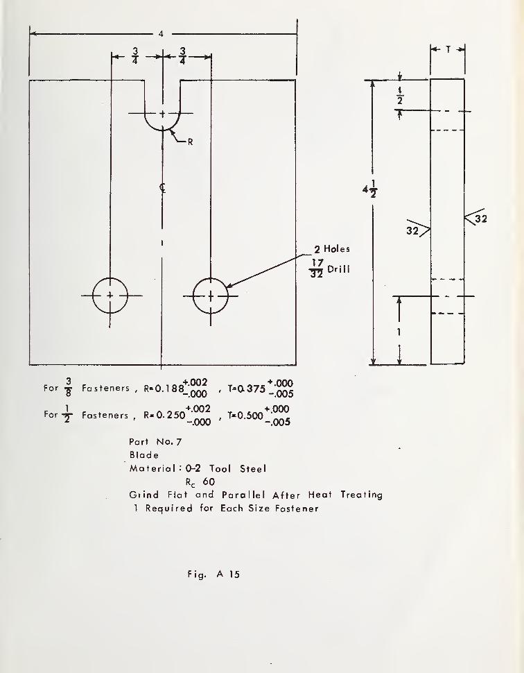
Part No. 7
Blade
Material • 0-2 Tool Steel
Rc 60
Gfind Flat and Parallel After Heat Treating
1 Required for Each Size Fastener
Fig. A 15

i


1

APPENDIX B
Tension-Bending Fatigue Test Fixtures for 0.250-inProtruding Head Threaded Airframe Fasteners
Detailed drawings for the fixtures used for the tests described inthis paper are given in figures Bl to B6.


L,
0.0.
25
z T ^ ^I I
I'
J L
Hi)
.1 I
I
I
._jI
I
JI
I
I
PART NO- DESCRIPTION
1 Test Specimen
2 Nut
3 Knife Edge
4 Collar
5 Retainer
6 6-32 Screw
7 Base Plate
8 Spacer
9 Top Load Plate
10 Botiom Load Plate
11 1-13 Screw
~1
) (
Fig. Bl - Tension - Bend ing Fixtures, Assembly


•-5 "V
\
>;... ..,
J- /J\ •4
4
-17.:;
1
1
A

1
1 -ff
Part No. 5
Retainer
Material: Cold Rolled Steel
1 Required
Fig. B3

0
;--r-
If. :
'
....jy.,.. ,.,,„.,; .„
\...\ -


""'^1"
4. ....J I
-V
.-1'
... .....

0)
CO
oZ
I
ou
o
-aa;
CM
O)
0)
~oO
700 _^6 oz - -z
•t- -I•-OnO Q. ^Q- CO <
o
00in
uOH -a
0)
3D-0)
Of

i

i1.6
9_
16
3
1—
r
' I
4 ^ 3
Drill and Tap
1-13 UNC
Part No. 9
Top Load Plate
Material: AISI 4340 Steel
Rc 41-43
1 Required
116
~3"
I •
4 J Ref
Drill and Tap
j-13 UNC
Part No. 10
Botto m Load Plate
Material: AISI 4340 Steel
Rc 41-43
1 Required
Fig. B6

-jv> -'V
i...
71-
•'.tv-
1
/ M " / ....
-4 - - ...

NBS-114A (REV. 7-73)
U.S. DEPT. OF COMM.RIRI 1 Or^ P A PM 1 r° DATA
SHEET
1. PUBLICATION OR REPORT NO.
NBSIR 74-465
2. Gov't AccessionIN O.
3. Recipient's Accession No.
4. TITLE AND SUBTITLE
Shear and Tension-Bending Fatigue Test Methods for
Threaded Airframe Fasteners
5. Publication Date
6. Performing Organization Code
7. AUTHOR(S)
Daniel J. Chwirut, Donald E. Marlowe, and James S. Steel
8. Performing Organ. Report No.
NBSIR 74-4659. PERFORMING ORGANIZATION NAME AND ADDRESS
NATIONAL BUREAU OF STANDARDSDEPARTMENT OF COMMERCEWASHINGTON, D.C. 20234
10. Project/Task/Work Unit No.
213044811. Contract/Grant No.
NADC Proj ect Order No
.
PO-8-0033
12. Sponsoring Organization Name and Complete Address (Street, City, State, ZIP)
Aero Structures DepartmentNaval Air Development CenterDepartment of the NavyWarminster^ Pennsylvania 18974
13. Type of Report & PeriodCovered
Final14. Sponsoring Agency Code
15. SUPPLEMENTARY NOTES
16. ABSTRACT (A 200-word or less factual summary of most significant information. If document includes a significant
bibliography or literature survey, mention it here.)
Fatigue test methods for threaded airframe fasteners loaded in other than direct tensionare described. The types of loading considered are single shear, double shear, andtension-bending. The test fixtures used in these tests are described. Results of testson lots of fasteners from different manufacturers indicate that fasteners consideredidentical on the basis of direct tension procurement tests exhibit different fatiguelife characteristics when loaded in shear and/or tension-bending. Thus the test methodsdescribed herein may be of future value as procurement tests for airframe fasteners.
17. KEY WORDS (six to twelve entries; alphabetical order; capitalize only the first letter of the first key word unless a propername; separated by semicolons)
Airframe fastener; double shear; fatigue; single shear; tension-bending; test methods
18. AVAILABILITY [^Unlimited 19. SECURITY CLASS(THIS REPORT)
21. NO. OF PAGES
!For Official Distribution. Do Not Release to NTIS
UNCL ASSIFIED
1' Order From Sup. of Doc, U.S. Government PrintingWashington, D.C. 20402. SD Cat. No. C13
Office 20. SECURITY CLASS(THIS PAGE)
22. Price
1 !Order From National Technical Information ServiceSpringfield, Virginia 22151
(NTIS)UNCLASSIFIED
USCOMM-DC 29042-P74