Embed Size (px)
Citation preview
Tim Gross, Jim Price, Scott Glaesemann
Functional Glasses: Properties and Applications for Energy and InformationJanuary 6-13 in Siracusa, Sicily, Italy
Sharp Contact Damage in Ion-Exchanged Cover Glass
© Corning Incorporated 2013

Overview
• Sharp point contact, the primary failure mode in ion-exchanged cover glass.
• Replication of field damage using diamond indenters– Role of indenter angle and rate of contact.
• Sharp scratch events, the source of highly visible cosmetic damage.
• Measurements of retained strength following sharp contact events.
2© Corning Incorporated 2013

Primary failure mode in ion-exchanged cover glass is sharp contact and associated flexure
Origin
Sharp contact Origin
•Sharp contact deformation is defined by the glass response. It occurs when the contact load is distributed over small contact area and elastic limit is exceeded resulting in permanent deformation.•Strength limiting flaw formation initiates within the permanent deformation region.•Crack extension to failure occurs as contact flaws extend through the depth of compressive layer.
3© Corning Incorporated 2013

Using diamond indentation to mimic the response from sharp contact
B. Lawn, Fracture of Brittle Solids, Cambridge Univ. Press, 1993.
Median crack Lateral crack
Loading Unloading
The Vickers diamond indenter is a 4-sided pyramid with angle between opposite faces 2a = 136o
4© Corning Incorporated 2013

Vickers indents in ion-exchanged glass produce the median/radial and lateral crack systems seen in field damage
Sharp Contact Field Damage
Damage produced by Vickers indenter
• Indentation is used to determine the resistance to the formation of strength limiting flaws, i.e. median/radial cracks, that are oriented perpendicular to the glass surface.
• The Vickers median/radial crack indentation threshold of an alkali aluminosilicate glass increases from ~500 gf for non-strengthened glass to ~7000 gf for glass ion-exchanged to compressive stress (CS) ~700 MPa and depth of layer (DOL) ~50 microns.
• With DOL sufficient to contain the deformation region, the Vickers median/radial crack initiation load increases with CS for a given glass type. For example, if the depth of compressive layer is fixed at 50 microns, an alkali aluminosilicate sample with surface compressive stress of 500 MPa has a cracking threshold of 4 kgf, while a sample with surface compressive stress of 800 MPa has a cracking threshold of 7 kgf.
5© Corning Incorporated 2013

Deformation of ion-exchanged glass• Following ion-exchange, glasses still deform by the same
mechanism as in the non-ion-exchanged glass.• Normal glasses deform primarily by a shearing mechanism
both pre- and post- ion-exchange.• However, propagation of shear damage into median/radial
cracks is limited due to the compressive stress field.
Cross-section of 1 kgf Vickers indentation in non-ion-exchanged normal glass
Cross-section of 1 kgf Vickers indentation in ion-exchanged normal glass
6© Corning Incorporated 2013

Deformation mechanisms
• The resulting permanent deformation by sharp contact is the result of two competing mechanisms: shear deformation and densification. Deformation mechanism depends on glass structure (i.e. network connectivity, free volume), contact geometry, and rate of contact.
• Shear deformation – Volume displacing mechanism leads to “pile-up” at the periphery of the indent. Indentation with sharper indenter tips favor shear deformation.
• Densification- Glass is compacted rather than displaced. Indentation with blunter indenter tips favor densification. High rate contact also appears to favor densification.
7© Corning Incorporated 2013

Effect of indenter sharpness on amount of densification
Yoshida et al., J. Mater. Res., 25, 2203-2211 (2010).
•Blunt tips produce more densification during indentation.•During densification the glass is compacted rather than displaced.•Subsequent sub Tg heat-treatment leads to nearly a full recovery of the deformed material.
•Sharp tips produce more shear deformation during indentation.•This deformation leads to displaced material that piles up at the edges of the indent impression.•Heat-treatment does not recover material that has deformed by plastic flow.
Using densification recovery technique described by Mackenzie [JACS 46(1963) 461], Yoshida et al. demonstrated the reduction in densification with increasing indenter sharpness.
8© Corning Incorporated 2013

Cross-section of indents made in non-IXed alkali aluminosilicate at 500 gf with various indenter tips
120o tip 136o tip 150o tip
Deformation by a shearing mechanism creates subsurface cracking damage in the deformation region that initiates larger crack systems, i.e. median/radial and lateral cracks. The extension of crack systems is driven by the greater residual stress that results from volume-displacing shear deformation.
Deformation by densification produces less sub-surface damage and less residual stress, so that the threshold load required to initiate cracking systems increases.
Densification increases resistance to “normal” cracking. However, as the degree of densification increases, the propensity towards cone cracking also increases.
Sharper, more shear Blunter, more densification
9
T.M. Gross, ACerS Fractography VI Ceramic Transactions Vol. 320 (2012) 113-122.
© Corning Incorporated 2013

Indentation cracking behavior on the surface in non-IXed parts also indicates the change in deformation mechanism towards densification as the contact becomes blunter
Indenter tipNon-ion-exchanged median/radial
cracking threshold (gf)Ion-exchanged median/radial cracking
threshold (gf)120o 15-30 50-100136o 300-500 5000 - 7000150o 7000 - 8000 >10,000
120o tip at 30 gf
Vickers 136o tip at 500 gf
150o tip at 8000 gf
Normal sharp cracking behavior indicates that deformation occurs with significant shear deformation
Mixed normal/anomalous cracking behavior indicates that deformation is occurring with greater densification
Ring crack
Resistance to the formation of cracks increases as the deformation mechanism tends towards densification
10
T.M. Gross, ACerS Fractography VI Ceramic Transactions Vol. 320 (2012) 113-122.
© Corning Incorporated 2013
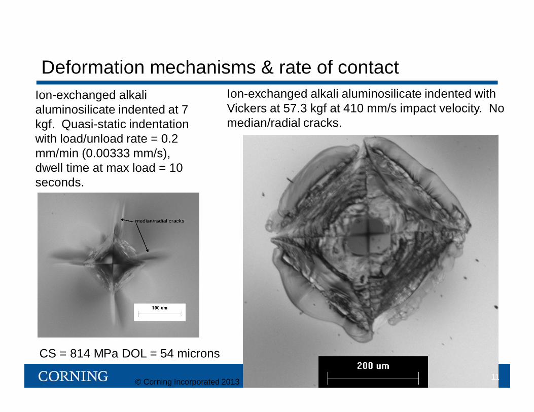
Deformation mechanisms & rate of contactIon-exchanged alkali aluminosilicate indented with Vickers at 57.3 kgf at 410 mm/s impact velocity. No median/radial cracks.
Ion-exchanged alkali aluminosilicate indented at 7 kgf. Quasi-static indentation with load/unload rate = 0.2 mm/min (0.00333 mm/s), dwell time at max load = 10 seconds.
11
CS = 814 MPa DOL = 54 microns
© Corning Incorporated 2013
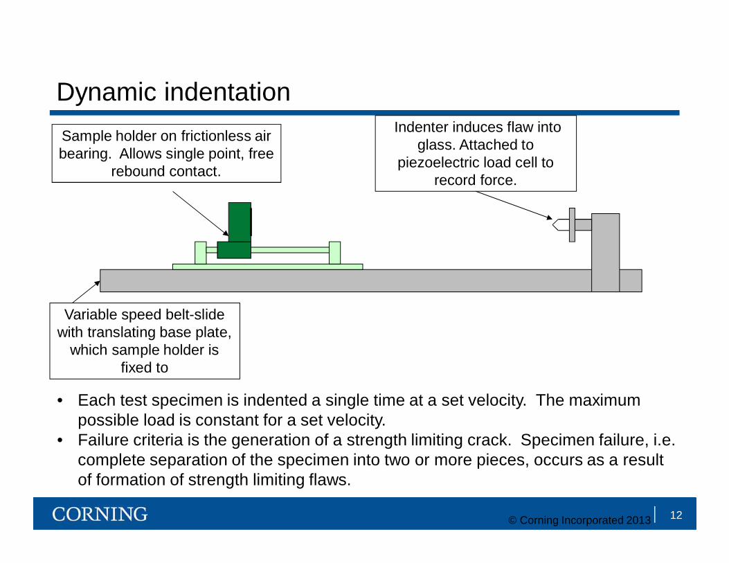
Dynamic indentationSample holder on frictionless air bearing. Allows single point, free
rebound contact.
Indenter induces flaw into glass. Attached to
piezoelectric load cell to record force.
Variable speed belt-slide with translating base plate,
which sample holder is fixed to
12
• Each test specimen is indented a single time at a set velocity. The maximum possible load is constant for a set velocity.
• Failure criteria is the generation of a strength limiting crack. Specimen failure, i.e. complete separation of the specimen into two or more pieces, occurs as a result of formation of strength limiting flaws.
© Corning Incorporated 2013

Dynamic Vickers median/radial cracking threshold is substantially higher than for quasi-static indentation
• For quasi-static Vickers indentation, median/radial cracks form during unloading.• During dynamic Vickers indentation, median/radial cracks form during loading.• Increased contact stress on median plane during loading is an indicator of
densification according to Yoffe [Phil. Mag. A 46 (1982) 617]. Hint at a transition towards densification at high rate Vickers indentation?
Load
timeStrength limiting flaw formation and failure occurs during loading cycle for dynamic Vickers.
0
20
40
60
80
100
120
140
0 100 200 300 400 500 600 700 800
Inde
ntat
ion
Load
(kgf
)
Impact Velocity (mm/s)
Survivors FailuresCS = 814 MPa DOL = 54 microns
13
Each data point represents a single specimen indented under a set velocity.
Max
© Corning Incorporated 2013
Schematic of load/time curve for a given velocity

Indentations made at 4.5 kgf by dynamic and quasi-static indentation
IXed alkali aluminosilicate indented at 4.5 kgfusing dynamic indenter, contact event time (initial load to fully unloaded) was 1266 microseconds diagonal length ~ 116 microns.
IXed alkali aluminosilicate indented at 4.5 kgf using dynamic indenter, contact event time was 55 seconds, diagonal length ~ 120 microns.
14© Corning Incorporated 2013

2317 Vicker's indentationdynamic vs. quasi-static loading
0
10
20
30
40
50
60
70
80
90
100
-200 -150 -100 -50 0 50 100 150 200
radial distance, m
reta
rdat
ion,
nm
dynamci loadingquasi-static loading
center of indent
• Quantitative 2D grayscale maps of stress-induced optical retardation of 4.5 kgf indents made in alkali aluminosilicatespecimens using quasi-static and dynamic indentation. Magnitude of retardation is significantly larger for the quasi-static loading case.
• Stress-induced retardation profile comparison for alkali aluminosilicate indented using quasi-static and dynamic loading indicates a reduced amount of residual stress (reduced shear deformation) during dynamic indentation.
Optical retardation indicates a drop in residual stress for a given load during dynamic contact
15© Corning Incorporated 2013
Quasi-static Dynamic

Dynamic Indentation with sharper 120o indenter tip
0
5
10
15
20
25
0 50 100 150 200 250
Con
tact
Loa
d (k
gf)
Velocity (mm/s)
SurvivorsFailures
Load
time
Strength limiting flaw formation driven on unloading indicates subsurface damage coupled with higher residual stress in this load regime. Again, sharper contact promotes shear deformation.Higher load rate still improves the median/radial cracking threshold drastically over quasi-static indentation.
CS = 840 MPa DOL = 53 microns
16© Corning Incorporated 2013
Schematic of load/time curve for a given velocity
Strength limiting flaw formation and failure occurs during unloading cycle for dynamic indentation with sharper tip.
Max

Dynamic Indentation with sharper 120o indenter tipCS vs. DOL
17
0
5
10
15
20
25
0 50 100 150 200 250
Con
tact
Loa
d (k
gf)
Velocity (mm/s)
CS = 849 DOL = 43 survivorsCS = 849 DOL = 43 failuresCS = 366 DOL = 100 survivorsCS = 366 DOL = 100 failures
© Corning Incorporated 2013
Open symbols indicate failures, filled symbols indicate survivors. High compressive stress samples require much greater velocities/loads to cause failures under sharp dynamic indentation.

Replicating sharp contact scratches in ion-exchanged glass
(50x)
I. Initially, plastic deformation occurs without the presence of cracks.
II. Increased frictional forces cause minor frictive-type damage.III. Lateral cracking systems eventually cause highly visible
chipping at the surface.
Ramped Scratch using Knoop diamond
I II III
Example of Field Damage
18© Corning Incorporated 2013

Regime II damage in scratched glasses
•Shallow cracks on either side of the scratch groove tend to form prior to the onset of larger median and lateral cracking systems.• These have previously been described as radial cracks, but our measurements indicate that they are frictive since their presence depends on the surface quality of the glass being measured.•Frictive cracks initiate at the surface from pre-existing flaws and extend into the subsurface to form crescent shaped cracks.•At higher loads near-surface chipping connects these cracks.
Radial cracksor
frictive damage?
Scratch direction
Focusing into the subsurface reveals that this damage appears to be frictive in nature.
19© Corning Incorporated 2013

Subsurface look at scratch damage in non-ion-exchanged glassMedian crack formation occurs first and is followed by lateral cracking
Median Crack Median CrackMedian Crack
Lateral Crack
Scribe LineScribe Line
Lateral Crack Intersects Surface
Increasing load Increasing load
V.R. Howes and A. Szameitat, J. Mater. Sci. Letters 3 (1984) 872-874.
20© Corning Incorporated 2013
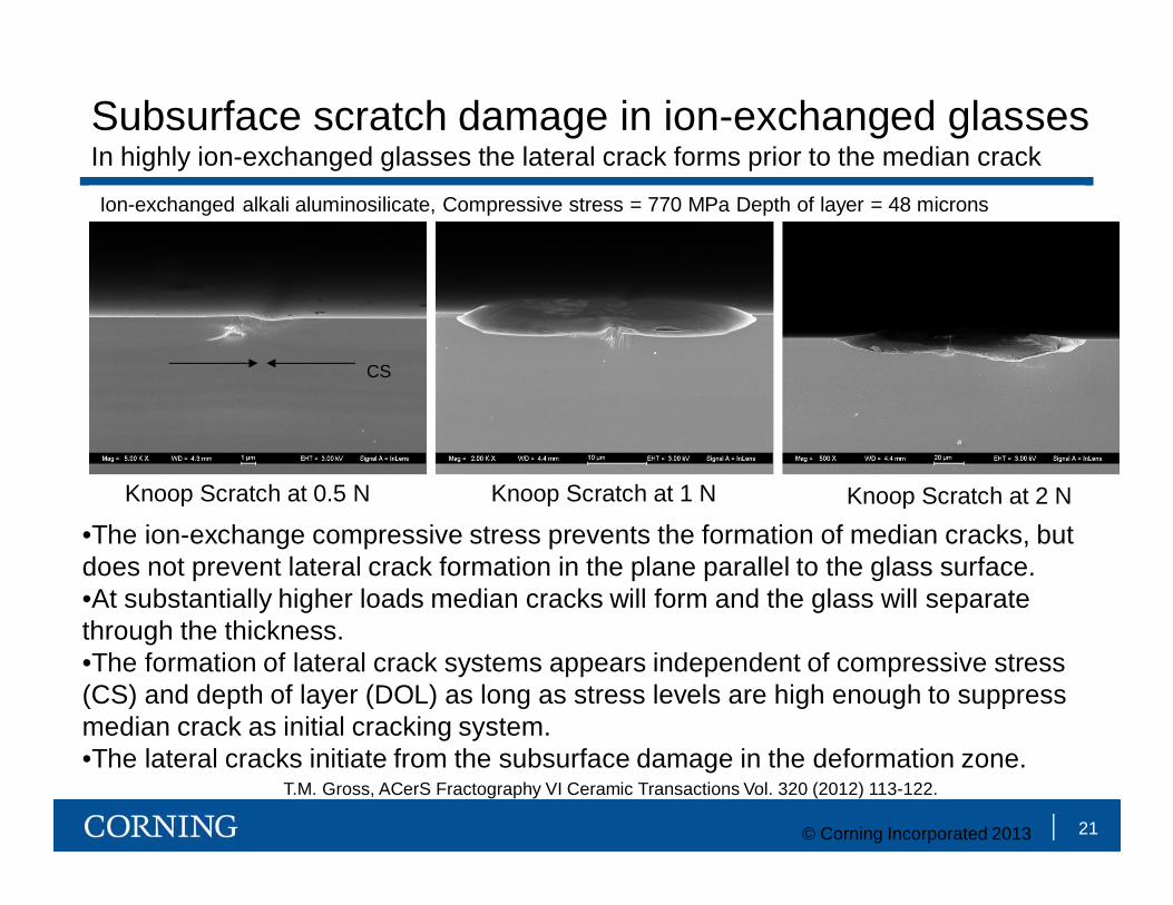
Subsurface scratch damage in ion-exchanged glassesIn highly ion-exchanged glasses the lateral crack forms prior to the median crack
Knoop Scratch at 0.5 N Knoop Scratch at 1 N Knoop Scratch at 2 N
•The ion-exchange compressive stress prevents the formation of median cracks, but does not prevent lateral crack formation in the plane parallel to the glass surface.•At substantially higher loads median cracks will form and the glass will separate through the thickness.•The formation of lateral crack systems appears independent of compressive stress (CS) and depth of layer (DOL) as long as stress levels are high enough to suppress median crack as initial cracking system.•The lateral cracks initiate from the subsurface damage in the deformation zone.
CS
Ion-exchanged alkali aluminosilicate, Compressive stress = 770 MPa Depth of layer = 48 microns
21© Corning Incorporated 2013
T.M. Gross, ACerS Fractography VI Ceramic Transactions Vol. 320 (2012) 113-122.
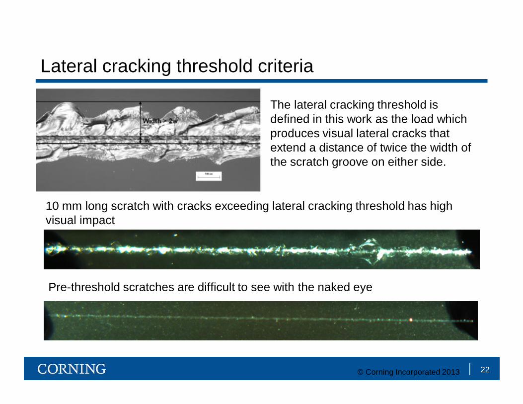
Lateral cracking threshold criteria
The lateral cracking threshold is defined in this work as the load which produces visual lateral cracks that extend a distance of twice the width of the scratch groove on either side.
10 mm long scratch with cracks exceeding lateral cracking threshold has high visual impact
Pre-threshold scratches are difficult to see with the naked eye
22© Corning Incorporated 2013
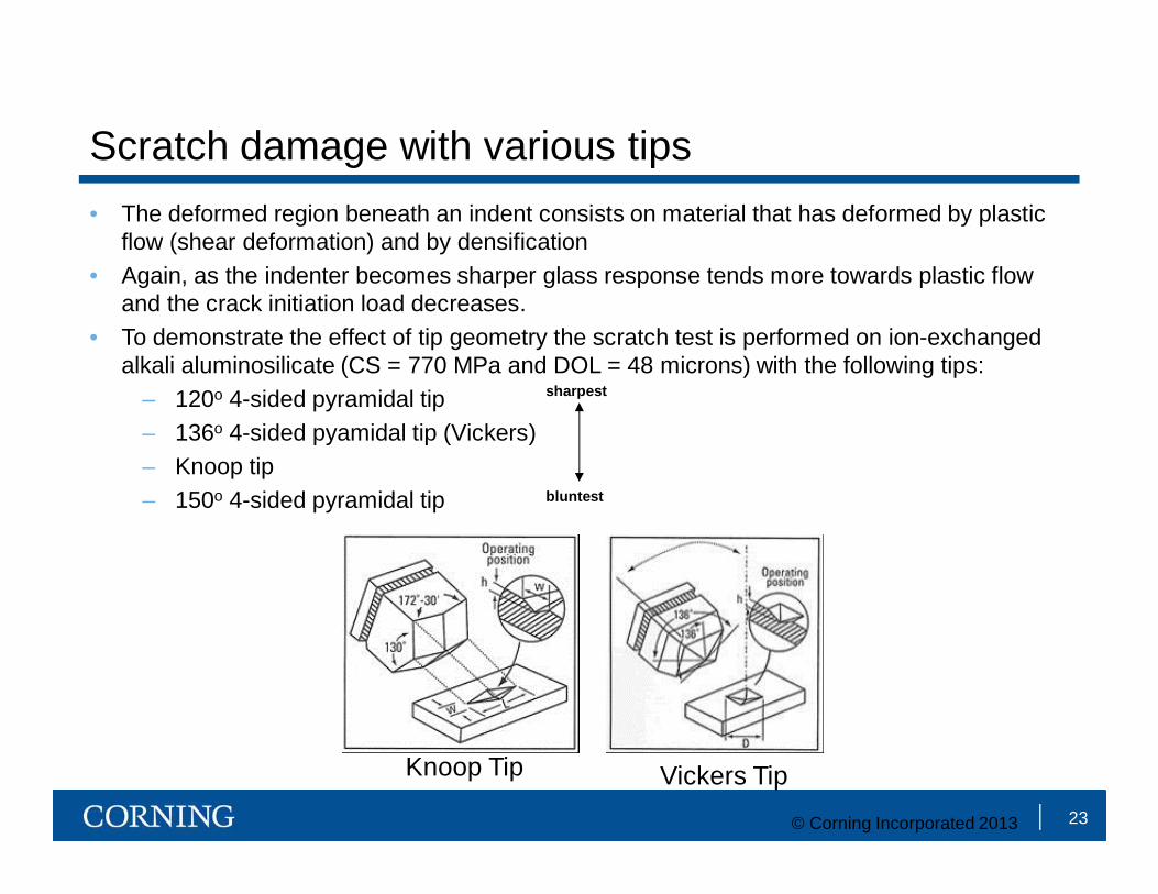
Scratch damage with various tips• The deformed region beneath an indent consists on material that has deformed by plastic
flow (shear deformation) and by densification• Again, as the indenter becomes sharper glass response tends more towards plastic flow
and the crack initiation load decreases.• To demonstrate the effect of tip geometry the scratch test is performed on ion-exchanged
alkali aluminosilicate (CS = 770 MPa and DOL = 48 microns) with the following tips:– 120o 4-sided pyramidal tip– 136o 4-sided pyamidal tip (Vickers)– Knoop tip– 150o 4-sided pyramidal tip
Knoop Tip Vickers Tip
sharpest
bluntest
23© Corning Incorporated 2013

Scratches in ion-exchanged alkali aluminosilicate with 120o 4-sided pyramidal tip (sharpest tip)
0.25 N
0.5 N
24© Corning Incorporated 2013
T.M. Gross, ACerS Fractography VI Ceramic Transactions Vol. 320 (2012) 113-122.
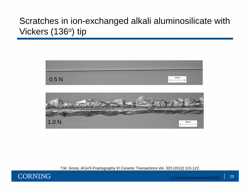
Scratches in ion-exchanged alkali aluminosilicate with Vickers (136o) tip
0.5 N
1.0 N
25© Corning Incorporated 2013
T.M. Gross, ACerS Fractography VI Ceramic Transactions Vol. 320 (2012) 113-122.

Scratches in ion-exchanged alkali aluminosilicate with Knoop tip
1 N
2 N
3 N
4 N26© Corning Incorporated 2013
T.M. Gross, ACerS Fractography VI Ceramic Transactions Vol. 320 (2012) 113-122.

Scratches in ion-exchanged alkali aluminosilicate with 150o 4-sided pyramidal tip (least sharp tip)
5 N
10 N
15 N
20 N
Maximum of load cell
27© Corning Incorporated 2013
T.M. Gross, ACerS Fractography VI Ceramic Transactions Vol. 320 (2012) 113-122.

Retained strength
• The measurement of ring-on-ring strength before and after introduction of controlled damage can be a useful tool to quantify and understand flaw introduction and its impact on mechanical performance
• Controlled flaws can be introduced as scratches, indentation damage, or as grit blast abrasion
• This approach provides a convenient means to simulate field failures in a controlled manner.
• If flaws enveloped in compression, want high CS.Flaw populations on the surface
SLS Deep DOL
28© Corning Incorporated 2013
Ring-on-ring testing of Vickers scratches
29
0.0 0.5 1.0 1.5 2.0 2.5 3.00
200
400
600
800
1000
1200
1400
1600
1800
Gorilla Glass Ion-Exchanged Soda-Lime Silicate Glass
Rin
g-on
-Rin
g Lo
ad a
t Fai
lure
(N)
Scratch Load (N)
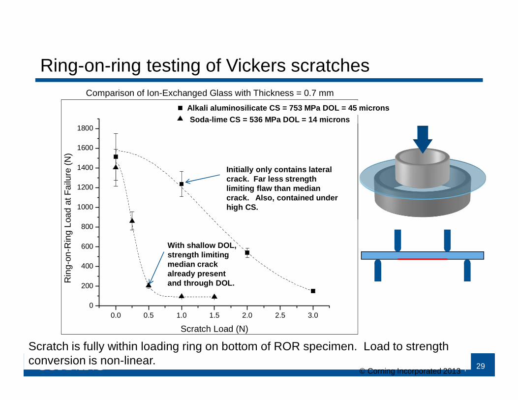
Comparison of Ion-Exchanged Glass with Thickness = 0.7 mmAlkali aluminosilicate CS = 753 MPa DOL = 45 micronsSoda-lime CS = 536 MPa DOL = 14 microns
Initially only contains lateral crack. Far less strength limiting flaw than median crack. Also, contained under high CS.
With shallow DOL, strength limiting median crack already present and through DOL.
Scratch is fully within loading ring on bottom of ROR specimen. Load to strength conversion is non-linear.
© Corning Incorporated 2013
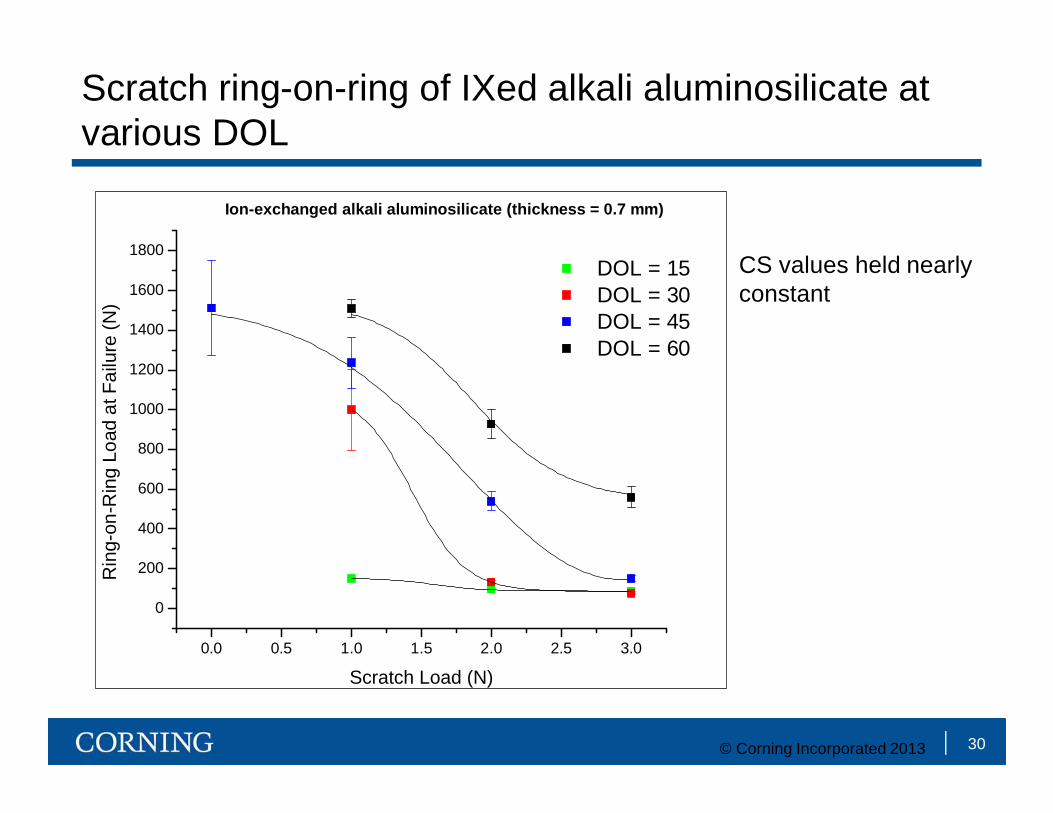
Scratch ring-on-ring of IXed alkali aluminosilicate at various DOL
30
0.0 0.5 1.0 1.5 2.0 2.5 3.0
0
200
400
600
800
1000
1200
1400
1600
1800 DOL = 15 DOL = 30 DOL = 45 DOL = 60
Rin
g-on
-Rin
g Lo
ad a
t Fai
lure
(N)
Scratch Load (N)
Ion-Exchanged Gorilla Glass (thickness = 0.7 mm)
CS values held nearly constant
Ion-exchanged alkali aluminosilicate (thickness = 0.7 mm)
© Corning Incorporated 2013

SiC abrasion causes radial/median cracks to form in both soda-lime and alkali aluminosilicate glasses. Irregular shapes of particles cause damage from a wide range of contact geometries.
Silicon carbide 60 RA
90 grit SiC particles
Radialcrack
Damage from SiC abrasion
31© Corning Incorporated 2013
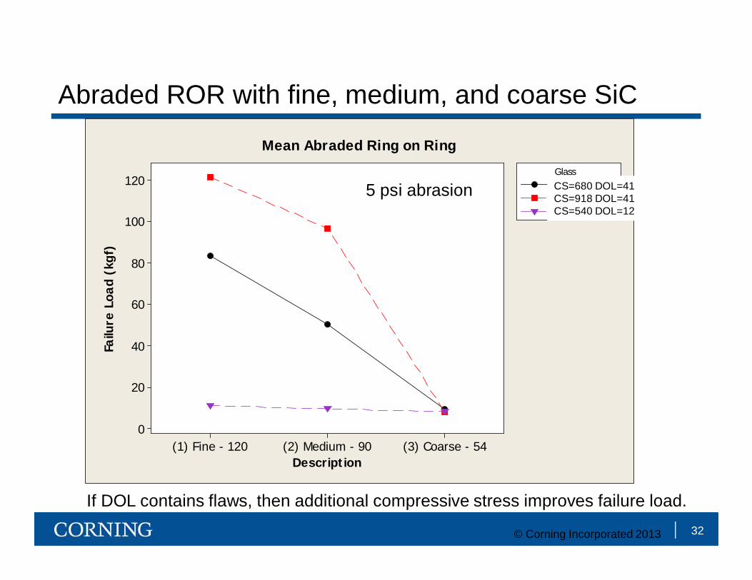
Abraded ROR with fine, medium, and coarse SiC
32
(3) Coarse - 54(2) Medium - 90(1) Fine - 120
120
100
80
60
40
20
0
Description
Failu
re L
oad
(kgf
)
2318 680/412319 918/41SLS 540/12
Glass_
Mean Abraded Ring on Ring
5 psi abrasion CS=680 DOL=41CS=918 DOL=41CS=540 DOL=12
If DOL contains flaws, then additional compressive stress improves failure load.
© Corning Incorporated 2013

90 Grit SiC Abrasion at various pressures on 0.6 mm alkali aluminosilicate
33
• Strength limiting flaws are generated at each abrasion pressure used.• If DOL contains the flaw, the retained load at failure will increase with compressive
stress to the flaw depth.• Low CS, deep DOL parts can contain very deep flaws, however cannot achieve high
strength even at shallow flaw depths. Non-abraded, low CS samples are also considerably weaker than high CS samples when testing samples similarly handled.
0
20
40
60
80
100
120
0 5 10 15 20 25 30
RO
R L
oad
at F
ailu
re (k
gf)
Abrasion Pressure (psi)
CS = 849 MPa DOL = 43 microns
CS = 366 MPa DOL = 100 microns
© Corning Incorporated 2013

• The formation of strength limiting flaws by sharp contact depends on both the contact geometry and the rate of contact.
– Sharper indenters promote shear deformation, blunter indenters promote densification
– Quasi-static indentation promotes shear deformation, dynamic indentation promotes densification
• The resistance to the formation of strength limiting flaws is increased with higher compressive stress.
• Cosmetic damage in the form of highly visible lateral crack-containing scratches is also highly dependent on contact geometry.
• The retained strength following sharp contact can be measured using controlled damage introduction following by ROR. Key to retained strength is enveloping the flaw within the DOL and under as high stress as possible (within safe limits of frangibility).
34
Summary
© Corning Incorporated 2013

Indentation in N2
Indentation in IXed alkali aluminosilicate in dry N2atmosphere at 15 kgf
•Indentation N2 glovebag increases indentation threshold 2X.•Water was removed from air, but adsorbed water on glass and diamond surfaces was not removed.•High speed indentation is expected to prevent sufficient water diffusion into glass.
BACKUP SLIDES
35

Water diffusion into glass during indentation?Evidence of Water entry into glass during indentation
K. Hirao and M. Tomozawa J. Am. Ceram. Soc. 70 497-502 (1987)
Hardness vs. loading duration in various environments
BACKUP SLIDES
36

Water diffusion into glass has also been shown to reduce indentation crack initiation load
•Water diffuses into glass occurs in both air and water environments. •The water uptake is dependent on contact time.•Contact time for dynamic indentation ranges from 200 to 600 microseconds.•Contact time for quasi-static indentation is ~30s. Around 100,000 times longer than dynamic indentation.
K. Hirao and M. Tomozawa J. Am. Ceram. Soc. 70 497-502 (1987)
Crack initiation load vs. loading duration in different environments
Fused Silica
BACKUP SLIDES
37