Embed Size (px)
Citation preview
Doc# E149703 V.1.08 QS - 1
Shark® 200 Meter Quickstart
Electro Industries/GaugeTechThe Leader In Power Monitoring and Smart Grid SolutionsElectro Industries/GaugeTechThe Leader In Power Monitoring and Smart Grid Solutions
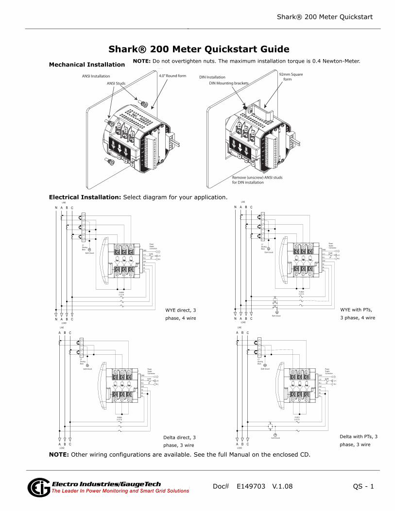
Shark® 200 Meter Quickstart GuideMechanical Installation
Electrical Installation: Select diagram for your application.
NOTE: Other wiring configurations are available. See the full Manual on the enclosed CD.
DIN mounting bracket
Top mounting bracket groove
Bottom
DIN Mounting brackets
Remove (unscrew) ANSI studs for DIN installation
DIN Installation92mm Square form
ANSI Installation ANSI Studs
4.0” Round form
lc
HI
LO
lb
HI
LO
la
HI
LO
Earth GroundL(+)
Power SupplyConnection
N(-)
L(+)
GND
N(-)
Vref
Va
VbVc
LINE
LOAD
CT ShortingBlock
FUSES3 x 0.1A
FUSE
3A
C
C
B
B
A
A
N
N
lc
HI
LO
lb
HI
LO
la
HI
LO
Earth Ground
Earth Ground
L(+)
Power SupplyConnection
N(-)
L(+)
GND
N(-)
Vref
Va
VbVc
LINE
LOAD
CT ShortingBlock
FUSES3 x 0.1A
FUSE
3A
C
C
B
B
A
A
N
N
lc
HI
LO
lb
HI
LO
la
HI
LO
Earth Ground
Earth Ground
L(+)
Power SupplyConnection
N(-)
L(+)
GND
N(-)
Vref
Va
VbVc
LINE
LOAD
CT ShortingBlock
FUSES2 x 0.1A
FUSE
3A
C
C
B
B
A
A
WYE direct, 3
phase, 4 wire
Delta direct, 3
phase, 3 wire
lc
HI
LO
lb
HI
LO
la
HI
LO
Earth Ground
L(+)
Power SupplyConnection
N(-)
L(+)
GND
N(-)
Vref
Va
VbVc
LINE
LOAD
CT ShortingBlock
FUSES3 x 0.1A
FUSE
3A
C
C
B
B
A
A
NOTE: Do not overtighten nuts. The maximum installation torque is 0.4 Newton-Meter.
WYE with PTs,
3 phase, 4 wire
Delta with PTs, 3
phase, 3 wire
Doc# E149703 V.1.08 QS - 2
Shark® 200 Meter Quickstart
Electro Industries/GaugeTechThe Leader In Power Monitoring and Smart Grid SolutionsElectro Industries/GaugeTechThe Leader In Power Monitoring and Smart Grid Solutions
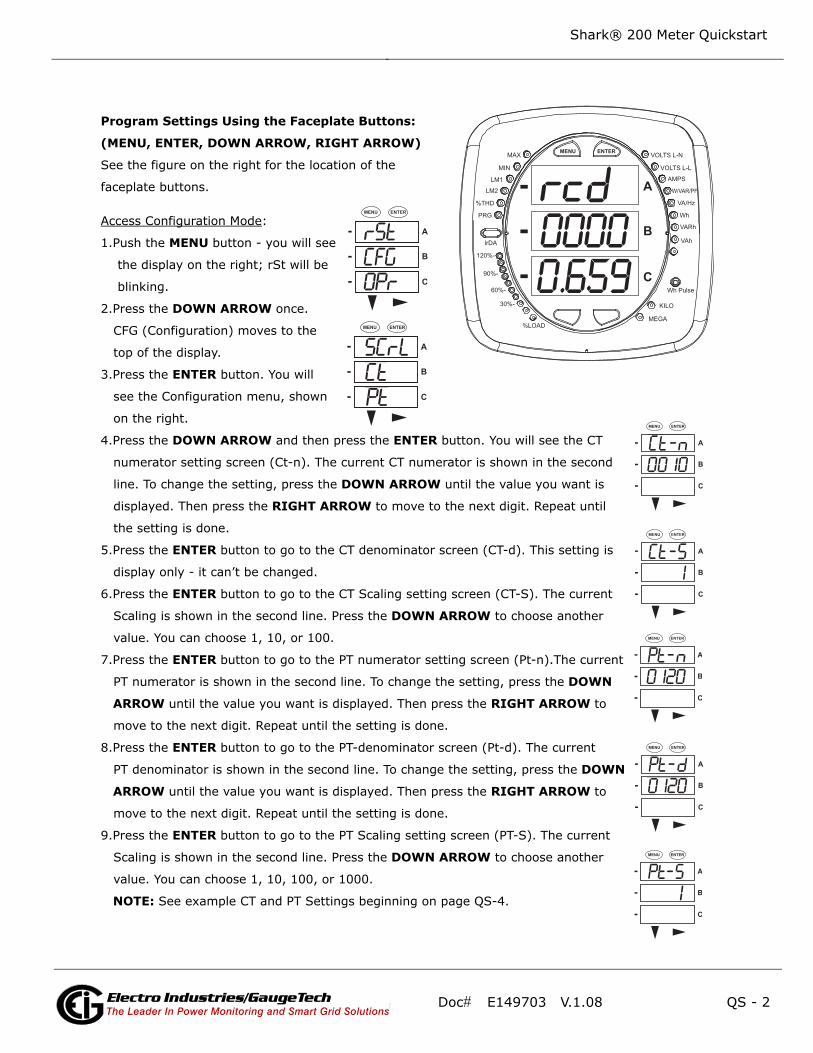
Program Settings Using the Faceplate Buttons:
(MENU, ENTER, DOWN ARROW, RIGHT ARROW)
See the figure on the right for the location of the
faceplate buttons.
Access Configuration Mode:
1.Push the MENU button - you will see
the display on the right; rSt will be
blinking.
2.Press the DOWN ARROW once.
CFG (Configuration) moves to the
top of the display.
3.Press the ENTER button. You will
see the Configuration menu, shown
on the right.
4.Press the DOWN ARROW and then press the ENTER button. You will see the CT
numerator setting screen (Ct-n). The current CT numerator is shown in the second
line. To change the setting, press the DOWN ARROW until the value you want is
displayed. Then press the RIGHT ARROW to move to the next digit. Repeat until
the setting is done.
5.Press the ENTER button to go to the CT denominator screen (CT-d). This setting is
display only - it can’t be changed.
6.Press the ENTER button to go to the CT Scaling setting screen (CT-S). The current
Scaling is shown in the second line. Press the DOWN ARROW to choose another
value. You can choose 1, 10, or 100.
7.Press the ENTER button to go to the PT numerator setting screen (Pt-n).The current
PT numerator is shown in the second line. To change the setting, press the DOWN
ARROW until the value you want is displayed. Then press the RIGHT ARROW to
move to the next digit. Repeat until the setting is done.
8.Press the ENTER button to go to the PT-denominator screen (Pt-d). The current
PT denominator is shown in the second line. To change the setting, press the DOWN
ARROW until the value you want is displayed. Then press the RIGHT ARROW to
move to the next digit. Repeat until the setting is done.
9.Press the ENTER button to go to the PT Scaling setting screen (PT-S). The current
Scaling is shown in the second line. Press the DOWN ARROW to choose another
value. You can choose 1, 10, 100, or 1000.
NOTE: See example CT and PT Settings beginning on page QS-4.
0.6590000
---
A
B
C
MENU ENTERMAX
MIN
LM1
LM2
%THD
PRG
VOLTS L-N
VOLTS L-L
AMPS
W/VAR/PF
VA/Hz
lrDA
Wh
VARh
VAh
120%-
90%-
60%-
30%-
%LOADMEGA
KILO
Wh Pulse
A
B
C
-
-
-
MENU ENTER
A
B
C
-
-
-
MENU ENTER
A
B
C
-
-
-
MENU ENTER
A
B
C
-
-
-
MENU ENTER
A
B
C
-
-
-
MENU ENTER
A
B
C
-
-
-
MENU ENTER
A
B
C
-
-
-
MENU ENTER

Doc# E149703 V.1.08 QS - 3
Shark® 200 Meter Quickstart
Electro Industries/GaugeTechThe Leader In Power Monitoring and Smart Grid SolutionsElectro Industries/GaugeTechThe Leader In Power Monitoring and Smart Grid Solutions
10.Press the ENTER button to go to the Connection setting screen (Cnct). The current
setting is shown in the second line. Press the DOWN ARROW to choose another
value. You can choose 3 EL (element) WYE, 2 Ct del (Delta), or 2.5 EL WYE.
11.Press the ENTER button to go to the meter Address setting screen (Adr). The
meter’s current address is shown in the second line. To change the setting, press
the DOWN ARROW until the value you want is displayed. Then press the RIGHT
ARROW to move to the next digit. Repeat until the setting is done. Valid address-
es are from 001 through 247. IMPORTANT! If you are using the Ethernet
option (INP100S) do not change any settings - leave the address as 001.**
12.Press the ENTER button to go to the meter Baud Rate setting screen (bAUd). The
meter’s current Baud Rate is shown in the second line. Press the DOWN ARROW
to choose another Baud Rate. You can choose 9600 (choose this for RS485
connection), 19.2 (19200), 38.4 (38400) or 57.6 (57600). IMPORTANT! If you
are using the Ethernet option, do not change any settings - leave the Baud Rate
as 57.6.**
13.Press the ENTER button to go to the meter Protocol setting screen (Prot). The
meter’s current Protocol is shown in the second and third lines. Press the DOWN
ARROW to choose another communication Protocol. You can choose Mod rtU
(Modbus RTU; choose this for RS485 connection), Mod ASCI (Modbus ASCII),
or dnp (DNP 3.0). IMPORTANT! If you are using the Ethernet option, do not
change any settings - leave the protocol as Mod rtU.**
14.Press the ENTER button to go to the Scroll setting screen (SCrL). The current
setting is shown in the second line. Press the DOWN ARROW to choose another
setting. You can choose YES (the meter readings will scroll on the display) or no
(the meter readings will not scroll on the display).
15.Press the MENU button twice. You will see the Store Settings screen (Stor ALL?)
The default setting is YES. To save the settings you’ve made, press the ENTER
button. You will see the confirmation screen (Stor ALL done) and then the meter
resets.
NOTE: If you do not want to save your settings, press the RIGHT ARROW. YES
changes to no. Press the ENTER button.
**The Shark® 200 meter’s Ethernet communication settings are the default settings of
Address 1, Baud Rate 57.6 and Protocol Mod rtU. See the Shark® 200/200T Meter Installation and
Operation Manual on the enclosed CD for additional configuration instructions for the Shark® 200
meter’s Ethernet port
A
B
C
-
-
-
MENU ENTER
A
B
C
-
-
-
MENU ENTER
A
B
C
-
-
-
MENU ENTER
A
B
C
-
-
-
MENU ENTER
A
B
C
-
-
-
MENU ENTER
A
B
C
-
-
-
MENU ENTER
A
B
C
-
-
-
MENU ENTER

Doc# E149703 V.1.08 QS - 4
Shark® 200 Meter Quickstart
Electro Industries/GaugeTechThe Leader In Power Monitoring and Smart Grid SolutionsElectro Industries/GaugeTechThe Leader In Power Monitoring and Smart Grid Solutions
Example CT Settings:
200/5 Amps: set the Ct-n value as 200, Ct-S value as 1.
800/5Amps: set the Ct-n value as 800, Ct-S value as 1.
2000/5 Amps: set the Ct-n value as 2000, Ct-S value as 1
10,000/5 Amps: set the Ct-n value as 1000, Ct-S value as 10.
Example PT Settings:
14400/120 Volts: set the Pt-n value as 1440, Pt-d value as 120, Pt-S value as 10.
138000/69 Volts: set the Pt-n value as 1380, Pt-d value as 69, Pt-S value as 100.
345000/115 Volts: set the Pt-n value as 3450, Pt-d value as 115, Pt-S value as 100.
345000/69 Volts: set the Pt-n value as 0345, Pt-d value as 69, Pt-S value as 1000.
NOTE: For additional wiring options and programming information, refer to the Shark® 200/200T
Meter Installation and Operation Manual and the Communicator EXTTM 4.0 and MeterManager EXT
Software User Manual on the enclosed CD.
Shark® is a registered trademark of Electro Industries/GaugeTech. The distinctive shape, style, and overall appearance of the Shark® meter is a trademark of Electro Industries/GaugeTech.