Embed Size (px)
Citation preview

This document is downloaded from DR‑NTU (https://dr.ntu.edu.sg)Nanyang Technological University, Singapore.
Shaping high‑Q planar fano resonantmetamaterials toward futuristic technologies
Lim, Wen Xiang; Manjappa, Manukumara; Pitchappa, Prakash; Singh, Rajan
2018
Lim, W. X., Manjappa, M., Pitchappa, P., & Singh, R. (2018). Shaping high‑Q planar fanoresonant metamaterials toward futuristic technologies. Advanced Optical Materials, 6(19),1800502‑. doi:10.1002/adom.201800502
https://hdl.handle.net/10356/138748
https://doi.org/10.1002/adom.201800502
© 2018 WILEY‑VCH Verlag GmbH & Co. KGaA, Weinheim. All rights reserved. This paper waspublished in Advanced Optical Materials and is made available with permission ofWILEY‑VCH Verlag GmbH & Co. KGaA, Weinheim.
Downloaded on 26 Feb 2022 21:33:15 SGT
1
Article type: Progress Report
Shaping high-Q planar Fano resonant metamaterials towards futuristic technologies
Wen Xiang Lim, Manukumara Manjappa, Prakash Pitchappa, and Ranjan Singh*
Wen Xiang Lim, Manukumara Manjappa, Dr. Prakash Pitchappa, Prof. Ranjan Singh
Division of Physics and Applied Physics, School of Physical and Mathematical Sciences,
Nanyang Technological University, Singapore 637371, Singapore
Centre for Disruptive Photonic Technologies, The Photonics Institute, Nanyang
Technological University, 50 Nanyang Avenue, Singapore 639798
E-mail: [email protected]
Keywords: Fano resonance, metamaterials, plasmonics, high quality factor, future
applications
2
Abstract: Advances in plasmonic metamaterials have been rapidly evolving with
inventions aimed at developing metadevices with real world applications. In reality,
energy losses in plasmonic systems are prevalent and it is paramount to come up with
solutions that could overcome limitations that impede further advancements towards the
miniaturization of optoelectronics devices. High-Q Fano resonance as a scattering
phenomenon can be triggered easily by introducing asymmetry into plasmonics system,
and thus it offers a simple approach to reduce radiative losses through lineshape
engineering. High-Q Fano resonance possesses narrow linewidth and intensely confined
electromagnetic fields which makes it viable for wide-spread applications. The purpose
of this review is to consolidate the current advances or contributions that high-Q Fano
resonance has made in the metamaterials community. Two general modes of energy loss
including radiative and non-radiative losses are introduced and we examined possible
ways to overcome these challenges. Following which, applications based on high-Q Fano
resonance including sensors, lasing spaser and optical switch are introduced as we
embrace on the future of Fano resonance-based technologies.
3
1. Introduction
In the current era of science and technology, optics and photonics have become an
integral part of core technological platform that has transformed human lives as we know
of today. The researchers are continuously pushing forth the frontiers of modern optics
and photonic devices to achieve higher sensitivity, miniaturization, advancement in
functionality and more novel and intriguing applications. Without doubt, these efforts
have been the driving force towards the revolution in the fields of high speed
telecommunication, enhanced health technology, sensitive spectroscopy system, and
many more. At the backbone of these applications lies a set of unique features offered by
optics and photonics. The ultimate speed limit of photon due to its massless property led
to the telecommunication and internet revolutions as it could transfer huge capacity of
information over long distances with extremely low latency and power.[1, 2] For real
applications into telecommunications, a great deal of interest has been generated on
signal processors,[3] multiple-wavelength source,[4, 5] modulators[6] and frequency
combs[7, 8] to enable the integration of CMOS (complementary metal-oxide-
semiconductor)-compatible platforms. Furthermore, the non-destructive and remote
sensing capabilities of photonics has led to the improvements in health technology which
bring about label-free and non-invasive techniques with advanced sensing modalities that
facilitate early detection of disease-causing molecules.[9, 10, 11] The strong interaction
of materials to the various optical parameter such as amplitude, frequency, phase and
polarization has been instrumental in the development of sensitive spectroscopy system.
This allows for accurate and timely detection of gas molecules that provides several
4
benefits such as real-time monitoring of the environmental air quality, sensing explosive
traces for security and tracking of toxic gas leakage in clinical laboratory to ensure a safe
and healthy workplace.[12, 13, 14, 15] With significant steps taken to boost the quality of
our life, it is hard to imagine living without these technological devices that have
benefited us by contributing to the simplicity and convenience of human mankind in
several ways. More interestingly, the sensitivity, speed and accuracy of these optical
systems can be significantly enhanced through optical resonator cavities that strongly
confine the interacting optical field in an extremely narrow region or increase the
interaction time by trapping the photon in the cavity. The performance of an optical
resonator is determined by its ability to trap the optical energy within the cavity and is
usually characterized by quality (Q) factor.
Q-factor is a dimensionless parameter that quantifies the amount of energy stored as a
ratio to the amount of energy lost per cycle through dissipation in a resonator system. In
other words, a resonator with low-Q loses energy more quickly over time due to stronger
damping. In electronic circuits, this is described by the equation,
𝑄 = 2𝜋𝑇𝑜𝑡𝑎𝑙 𝑒𝑛𝑒𝑟𝑔𝑦 𝑠𝑡𝑜𝑟𝑒𝑑
𝐸𝑛𝑒𝑟𝑔𝑦 𝑙𝑜𝑠𝑡 𝑖𝑛 𝑜𝑛𝑒 𝑝𝑒𝑟𝑖𝑜𝑑 (1)
whereby a period has 2π radians. In photonics, likewise the quality factor of a resonator
system is defined as the ratio of the resonant frequency, f0 to the full-width at half
maximum at the resonant position, δf and is written as,
𝑄 =𝑓0
𝛿𝑓 (2)
5
The full-width at half maximum (or resonance line-width) also corresponds to the
bandwidth which dictates the broadness of the resonance. For a less damping system, the
bandwidth is narrower with a higher-Q as compared to a system with higher damping,
and more energy can be stored. However, in all optical systems, energy losses are
unavoidable and they are associated with the radiative and non-radiative scattering of
charge carriers. The situation worsens and becomes more apparent as the overall size of
the system reduces from micro- to nanoscale dimensions.
As technology progresses, scaling down of devices becomes even more attractive with
customizable novel optical properties, hence pushing us to venture into another field of
research. Metamaterials is one such field that has gained huge research interests over the
past two decades, owing to the extreme spectral scalability, designed optical properties
and ease of realization and integration. Metamaterials are periodic arrangement of meta-
atoms which have been engineered to exhibit material properties not available in nature.
Their properties are mainly dependent on the size, shape, geometry and arrangements of
the meta-atoms. Futhermore, the meta-atoms are so small that miniaturization of future
devices look possible. By going smaller, we increase the portability of the device, allow
more components to be packed together, and in doing so, the operational efficiency will
be higher.[16, 17, 18, 19] However, advancements in technology are not always smooth-
sailing with several setbacks and challenges faced ahead. Energy losses remain one of the
critical issues for implementing feasible metamaterial-based devices, as it affects the
speed, efficiency and reliability of devices.

6
Radiative loss is inherent in metamaterials at lower frequencies, while energy loss at
higher frequencies is largely dominated by a non-radiative process (ohmic loss) owing to
the subwavelength nature of the resonators. Nevertheless, radiative loss remains present
in metamaterials across the electromagnetic spectrum. As an approach, without
significantly redesigning the architecture of the device, radiative loss can be reduced by
breaking the symmetry of the metamaterial which in turn induces a trapped mode
resonance termed as Fano resonance. Fano resonance does not interact directly with the
propagating electromagnetic wave and so radiative loss is suppressed. It is an extremely
peculiar dark resonance mode with very sharp asymmetric lineshape and high-Q factor.
Such high-Q resonance mode possesses a strong confinement of electric or magnetic field
which is imperative for useful applications. The Q-factor of a Fano lineshape can be
derived from the Fano fitting equation written as below,
𝑅 (𝜔) = 𝐴0 + 𝐹0
[𝑞+2(𝜔−𝜔0)
Γ]
2
1+[2(𝜔−𝜔0)
Γ]
2 (3)
whereby A0 and F0 are constant factors, q is the asymmetry parameter of the system
defined as the ratio between resonant and non-resonant state, ω0 is the resonance
frequency and Γ is the full-width at half maximum of the resonance frequency. Thereafter,
the Q-factor is calculated by 𝑄 =𝜔0
𝛤.[20, 21, 22, 23]
A higher Q-factor is evidently desirable in most metamaterial devices. Therefore, an
understanding on the behaviour of Q-factor is paramount to realizing scalable and
functional metamaterial devices across the electromagnetic spectrum. Appropriate loss-
7
engineering solution can be implemented to suit different situations (different frequency
regimes or geometrical parameters) so that an optimal high Q-factor can be obtained. It
has been reported that with a decreasing asymmetry, α (shape ratio parameter) or at lower
frequency regime, the Q-factor increases exponentially.[23] The increase in the Q-factor
can be attributed to the linewidth narrowing of the Fano resonance. However, the larger
Q-factor comes at the expense of a weaker resonance mode. This suggests that while a
maximum field confinement can be attained at the lowest asymmetry parameter, the
resonance has a low intensity, which is undesirable as high resolution and signal-to-noise
ratio are extremely critical for any sensor device. Hence, the Figure of Merit (FoM)
defined as the product of the Q-factor and the peak-to-dip intensity of the resonance
mode was devised to determine the optimized condition of the high-Q resonance which
considers the trade-off between the linewidth and resonance strength.[24] As compared to
other resonance modes in metamaterials, Fano resonance as a high-Q mode has great
potentials in many domains of technology [25].
In this review, we aim to present the latest developments of high-Q reports with emphasis
on Fano resonant metamaterials. We will introduce the models that have been used to
describe the origin of the resonance mode, types of system based on a variety of unit cell
designs to excite Fano resonance in the contemporary metamaterial society and their
application to current state-of-the-art devices. In addition, we will also introduce
superconductors as an alternative to metallic structures to lower non-radiative losses in
metamaterials. Our future outlook presents different loss-engineering schemes such as
8
unit cells arrangement or changing the material properties to all-dielectrics which also
offer solutions for reducing energy losses in subwavelength systems.
2. Characterization of Fano resonance
(a) Hybridization model
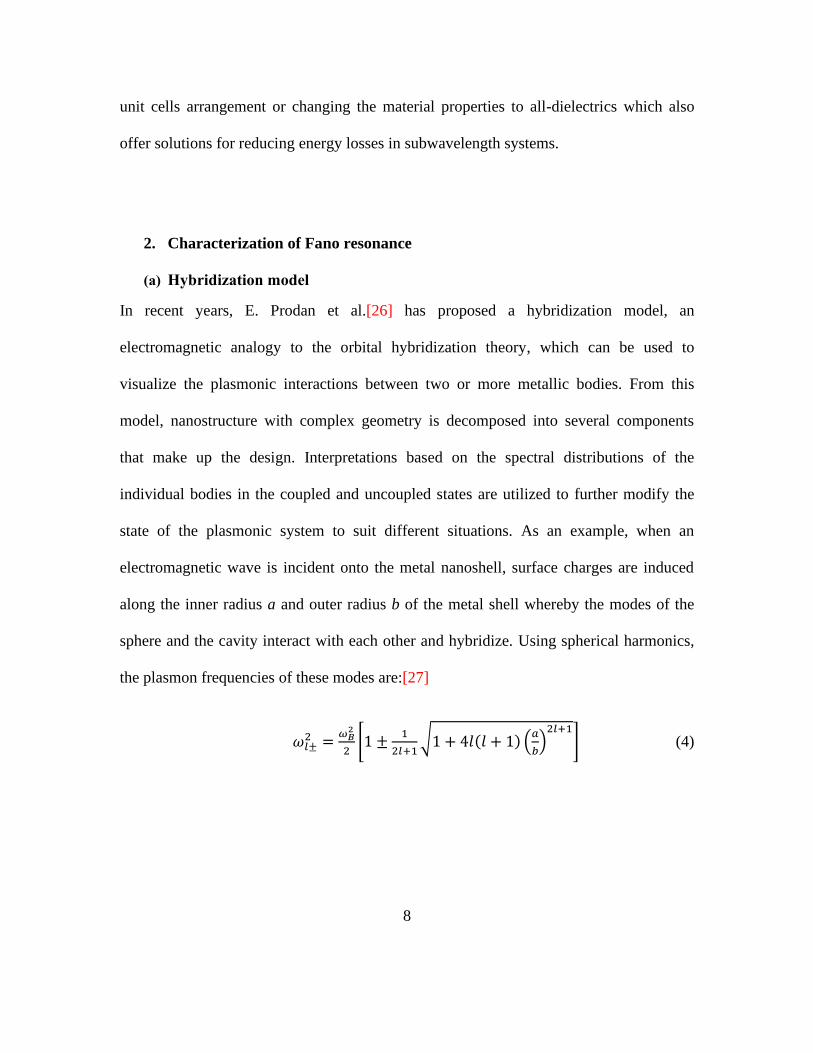
In recent years, E. Prodan et al.[26] has proposed a hybridization model, an
electromagnetic analogy to the orbital hybridization theory, which can be used to
visualize the plasmonic interactions between two or more metallic bodies. From this
model, nanostructure with complex geometry is decomposed into several components
that make up the design. Interpretations based on the spectral distributions of the
individual bodies in the coupled and uncoupled states are utilized to further modify the
state of the plasmonic system to suit different situations. As an example, when an
electromagnetic wave is incident onto the metal nanoshell, surface charges are induced
along the inner radius a and outer radius b of the metal shell whereby the modes of the
sphere and the cavity interact with each other and hybridize. Using spherical harmonics,
the plasmon frequencies of these modes are:[27]
𝜔𝑙±2 =
𝜔𝐵2
2[1 ±
1
2𝑙+1√1 + 4𝑙(𝑙 + 1) (
𝑎
𝑏)
2𝑙+1
] (4)
9
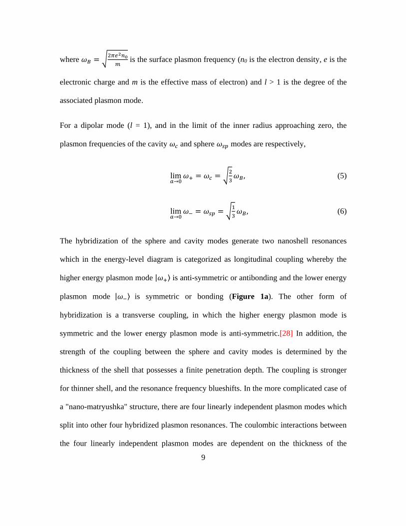
where 𝜔𝐵 = √2𝜋𝑒2𝑛0
𝑚 is the surface plasmon frequency (n0 is the electron density, e is the
electronic charge and m is the effective mass of electron) and l > 1 is the degree of the
associated plasmon mode.
For a dipolar mode (l = 1), and in the limit of the inner radius approaching zero, the
plasmon frequencies of the cavity 𝜔𝑐 and sphere 𝜔𝑠𝑝 modes are respectively,
lim𝑎→0
𝜔+ = 𝜔𝑐 = √2
3𝜔𝐵, (5)
lim𝑎→0
𝜔− = 𝜔𝑠𝑝 = √1
3𝜔𝐵, (6)
The hybridization of the sphere and cavity modes generate two nanoshell resonances
which in the energy-level diagram is categorized as longitudinal coupling whereby the
higher energy plasmon mode |𝜔+⟩ is anti-symmetric or antibonding and the lower energy
plasmon mode |𝜔−⟩ is symmetric or bonding (Figure 1a). The other form of
hybridization is a transverse coupling, in which the higher energy plasmon mode is
symmetric and the lower energy plasmon mode is anti-symmetric.[28] In addition, the
strength of the coupling between the sphere and cavity modes is determined by the
thickness of the shell that possesses a finite penetration depth. The coupling is stronger
for thinner shell, and the resonance frequency blueshifts. In the more complicated case of
a "nano-matryushka" structure, there are four linearly independent plasmon modes which
split into other four hybridized plasmon resonances. The coulombic interactions between
the four linearly independent plasmon modes are dependent on the thickness of the
10
dielectric spacer layer that separates the inner and outer metal shells. Therefore, as the
thickness of the dielectric spacer layer reduces, the coupling strength shifts from strong to
weak, and finally to an uncoupled case. Ever since the establishment of the model, it has
been applied as a simple and intuitive tool to understand the plasmonic resonances, which
include Fano resonance of complex nanostructures in several demonstrations.[29, 30, 31,
32, 33, 34, 35, 36].
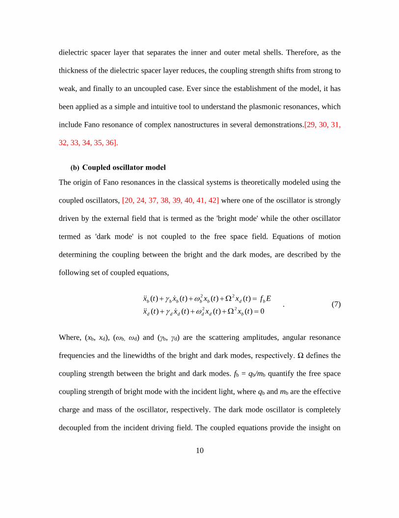
(b) Coupled oscillator model
The origin of Fano resonances in the classical systems is theoretically modeled using the
coupled oscillators, [20, 24, 37, 38, 39, 40, 41, 42] where one of the oscillator is strongly
driven by the external field that is termed as the 'bright mode' while the other oscillator
termed as 'dark mode' is not coupled to the free space field. Equations of motion
determining the coupling between the bright and the dark modes, are described by the
following set of coupled equations,
0)()()()(
)()()()(
22
22
=+++
=+++
txtxtxtx
Eftxtxtxtx
bddddd
bdbbbbb
. (7)
Where, (xb, xd), (ωb, ωd) and (γb, γd) are the scattering amplitudes, angular resonance
frequencies and the linewidths of the bright and dark modes, respectively. Ω defines the
coupling strength between the bright and dark modes. fb = qb/mb quantify the free space
coupling strength of bright mode with the incident light, where qb and mb are the effective
charge and mass of the oscillator, respectively. The dark mode oscillator is completely
decoupled from the incident driving field. The coupled equations provide the insight on

11
the interactions that leads to the Fano type of destructive interference in the amplitudes xb
and xd for contrasting linewidths b and d of bright and the dark modes. After solving for
the scattering amplitudes xb and xd in the coupled Eqn. 7, one can arrive at the
susceptibility expression for light-matter interactions given by,
+−+−−
+−=
))((
)(22224
22
bbdd
dd
ii
iK
(8)
The real part (Re[]) of the susceptibility expression in Eqn. 8 represents the dispersion
and the imaginary part (Im[]) gives the absorption losses in the system, where K is the
normalizing constant. 1-Im[] represents the transmission response of the system for the
appropriate fitting parameters of ωb, ωd, γb, γd and . The strength of the Fano resonance
depends on the coupling strength Ω which in turn relates to the asymmetry parameter α in
the metamaterial structures.
(c) Babinet's Principle for Electromagnetic Fields
Fano resonance has also been studied in complementary counterparts which are the
inverse design of positive metamaterial structures. As dictated by the Babinet's principle,
the transmission spectra of the positive structures and complementary structures should
sum up to the initial intensity of the electromagnetic wave that passes through as if
nothing existed.[43] In complementary structures, contrary to positive structures, the
electric field component should be interchanged with the magnetic field component of the
same electromagnetic wave. Hence, the transmission spectrum of the complementary
structure corresponds to a mirror-image of the the transmission spectrum of the positive

12
structure in a way that the peaks and dips are interchanged.[44, 45] Complementary split
ring resonators (CSRR) and positive split ring resonators (SRR) were first reported for
this phenomenon in metamaterials as shown in Figure 1b.[46] Near-field microscopy was
performed by A. Bitzer et. al and agreement between the theoretical, simulation and
experimental results fully validate the Babinet's principle.[47] The concentration of the
electric field in positive asymmetric split ring (ASR) relates to the accumulation of
surface current in complementary asymmetric split ring (CASR), and the surface current
accumulates at a region in positive ASR which relates to the concentration of the electric
field in CASR as shown in Figure 1c.[48] Subsequently, complementary structures of
various designs could be promising as polarization-sensitive graphene modulator,[49]
high-Q chiral metasurface for circular polarizers,[50] and directional filters.[51] In a
recent work, by strategically positioning dust particle along the nanoslit, the phononic
mode of the particle is detected as seen from the Fano lineshape, with maximum signal
towards the middle of the nanoslit. The presence of the dust particle breaks the symmetry
of the nanoslit, hence inducing a Fano signal on the plasmonic background. Narrower
nanoslits are beneficial for the detection of ultra fine dust particle via surface-enhanced
infrared absorption.[52] Thus, in many possible ways, Fano resonance is manifested in a
variety of systems composed of positive or complementary geometries.

13
Figure 1. a) The energy-level diagram of the hybridization between the sphere and cavity
modes. b) Measured transmission coefficient of a unit cell of SRR and CSRR, spectra
showing mirror-image of each other. c) Simulated surface current and electric field
distributions of the ASR and CASR, illustrating the Babinet's principle.
3. Classification of planar metallic Fano system

14
Planar metasurfaces are by far the easiest electromagnetic metamaterials to study light-
matter interactions in Fano resonant plasmonic systems due to the simplicity of the
fabrication process as compared to 3D metamaterials. In addition, due to the ease of
modifying the spectral response of the plasmon resonance, a plethora of unit cell designs
based on symmetry-broken configurations have been conceptualized to observe the Fano
resonant scattering phenomenon across a broad frequency (optical to terahertz) spectrum.
These planar Fano metamaterials can be broadly categorized into single-particle, dual-
particle or multi-particle systems based on the number of physical resonators present in a
single unit cell. In all of these systems, the contrast in the electromagnetic field
distribution among the sub-unit cells leads to the resonant coupling of the bright and dark
hybridized plasmon modes, which give rise to Fano resonance.[53] Bright mode is often
associated with the finite dipole mode of the metamaterial structure which is radiative in
nature and can interact with the far-field of the propagating electromagnetic wave in free
space. The spectrum of a bright mode is broadened due to radiative damping. Intuitively,
dark mode is non-radiative and prohibited in perfectly symmetric system. It is
represented by higher order mode that exhibit weak dipole moment and can only be
excited through near-field coupling with the radiative mode, hence making it accesible in
the spectroscopy (transmission, reflection or absorption) spectrum. Thus, Fano resonance
is also termed as "trapped-mode" resonance when first discovered in planar
metamaterials.[54] It is evident that symmetry breaking of the geometry of a unit cell,
permits the excitation of high-Q Fano resonance.

15
Single-particle
Nanodisk on its own, is one of the simplest geometrical structure that requires only one
particle in the unit cell to generate Fano resonance. The shape of the nanodisk is circular
and it possesses a 2 rotational symmetry. Therefore, to break the symmetry of the
nanodisk, a defect is introduced into the structure as a wedge which is angle controllable
(Figure 2a).[32] According to the hybridized model, the nanodisk contributes to the
broad dipole plasmon mode whereas the cut-out wedge contributes to the narrow
quadrupole plasmon mode. As a result, the spectral overlap of the two plasmon modes
lead to the effective generation of high-Q Fano resonance. Upon symmetry breaking (by
increasing the angle of the wedge), the intensity of the Fano resonance increases with a
distinct appearance of an asymmetric lineshape. However, further increasing the angle of
the wedge beyond the range of 90˚ to 105˚ weakens the resonance due to a reduction in
the edge charge density at the wedge. In addition, the radial size of the symmetry broken
nanodisks ranges from 140 to 200 nm where Fano resonance in the visible spectrum can
be easily achieved. Closely related is a distorted nanodisk, shaped in the form of an
ellipse. The elliptical disk fabricated on top of the Mylar film (membrane substrate) is
etched with double gaps along the long axis of the ellipse and separated by a rectangular
bar, whose position along the long axis determines the asymmetry of the system.[55] The
presence of the Fano resonance is illustrated clearly from the antiparallel surface currents
flowing on each side of the long axis. Further studies conducted on the properties of
membrane substrate reveal that membranes with small dielectric loss tangent and
thicknesses in the range of 10 to 50 µm are essential to achieving high-Q Fano resonance

16
at terahertz (THz) frequencies. This is attributed to a reduction in the amount of energy
dissipated through a less lossy substrate membrane, and so it interacts effectively with the
electromagnetic field, hence improving the sensitivity of THz membrane devices.
Dual-particle
Fano resonance in metamaterials was first reported in asymmetric split ring resonators
(ASRRs) in the microwave region that are composed of two arms with different
lengths.[54] Metallic resonators in the microwave region behave as almost perfect
conductors in which the main dissipative losses are attributed to absorption in substrates.
Despite of that, metallic resonators still losses energy radiatively. In ASRRs, the unit cell
is designed such that antisymmetric surface currents are excited on each arm with
unequal amplitude. The induced surface currents at the arms of each neighbouring unit
cell cancel with each other leaving only the peripheral surface currents at the edge of the
array, and the overall dipole moment is reduced greatly.[56] Furthermore, the magnetic
dipole of the excited Fano resonance does not interact with the propagating fields of the
electromagnetic wave and radiative losses to free space are significantly suppressed. An
experimentally measured high-Q of ~200 for Fano resonance has been obtained.[57] This
effect is more strongly observed in coherent arrays comprising of larger number of unit
cells, and the Q-factor of the Fano resonance can be improved.[56]
Other dual-particle unit cell systems that have been successful in their demonstrations of
high-Q Fano resonance include nanocross-bar,[33] asymmetric double bars,[58, 59, 60,

17
61, 62, 63, 64] ring-disk[31, 34] and concentric rings.[65] By employing the plasmon
hybridization model, the evolution of Fano resonance in nanocross-bar configuration was
elegantly pictured with the help of charge density distributions as depicted in Figure 2b.
For this instance, the excitation of the Fano resonance is only achievable for light
incident at grazing angle. This is because it introduces a field gradient along the surface
of the nanocross and results in a quadrupole mode (grey dot - forbidden for normal
incidence) appearing at the broad spectrum of the dipole nanocross (blue dot). As a result,
the quadrupole of the nanocross couples strongly with the dipole of the bar (black dot) to
form a hybridized mode, whose resonance mode spectrally overlaps with the broad dipole
spectrum of the bar. The destructive interference of both modes suppresses the radiative
dipole mode, hence creating a high-Q Fano resonance (green dot) at the optical
region.[33]
Thus far, the simplest asymmetric geometry model used for excitation of Fano resonance
at optical frequency is the asymmetric double bars.[58] Fano resonance originates from
the destructive interference between the bright mode of the double bars and the dark
mode of the asymmetric double bars which is indirectly excited through near-field
coupling. Electric field distributions attribute the bright mode to two in-phase dipoles
(parallel currents) that interfere constructively while the dark mode is due to destructive
interference of out-of-phase dipole oscillation (antiparallel currents).[59, 62] It was
further reported that at a certain length displacement for one of the double bar, the
plasmonic system is optimized and a high-Q Fano resonance can be obtained in the
infrared region.[59]
18
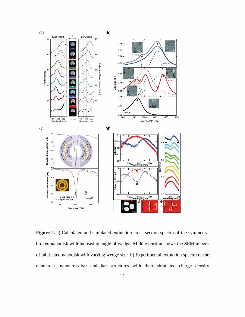
The geometrical structures reviewed so far are composed of elements whose strong field
enhancements are located near the sharp edges. Besides, circular or round geometrical
structures such as a ring-disk[29, 31, 34] or concentric rings have also been fabricated.
For a non-concentric ring-disk configuration, the inner dipole disk is either displaced
from the central position in the quadrupolar/higher order ring, or placed alongside the
ring. In a similar way to other configurations, the plasmon hybridization model provides
a visual interpretation to describe the nature of the plasmon modes. Here, Fano resonance
arises from the destructive interference between the dark quadrupolar ring plasmon mode
and bright dipole disk plasmon mode. Angle dependence of the incident light was also
performed on non-concentric ring-disk configuration which reveals the spectral shaping
of Fano resonance between asymmetric and symmetric shape, at which higher order
modes start appearing. Therefore, these higher order dark modes hybridize with the broad
continuum to form higher order Fano resonance modes. A relatively high-Q factor of 5.2
is obtained in the optical region.[29, 34] Concentric rings configuration has been
demonstrated across a wide electromagnetic spectrum which includes infrared,[65]
terahertz[66, 67] and microwave[68]. The benefit of concentric rings is that it is
independent of polarization, and so symmetry breaking is achieved without breaking the
geometry of the structure, but instead achieved through variation in the electromagnetic
field of the two rings. The difference in the circumference of the inner and outer rings
leads to induced currents which flow opposite to one another in both rings. Such current
configurations cancel each other, leaving an overall weak magnetic dipole moment which
does not scatter to the free space.[68]. Every unit cell in the metamaterial array does not
19
interact with the surrounding unit cells, hence concentric ring configuration is an
incoherent metamaterial array.[56] Further enhancement (more than 4 times) in the Q-
factor of concentric ring resonators is acheived by adding interdigitated finger pairs
between the inner and the outer rings, illustrated in Figure 2c. Such concept improves the
coupling between both rings so that the induced currents are able to cancel out more
effectively, leading to higher Q-factor.[66] An interception cut created at the minimum
electric field positions of the concentric rings allows the Fano resonance to be switched
on and off, by changing the polarization of light.[65]
Multi-particle
In multi-particle plasmonic systems, more than two sub-unit cells such as dolmen or
heptamers are used to excite Fano resonance. Although not as deeply explored as single
or dual-particle system, the multi-particle system provides more degree of freedom to
break the symmetry of a unit cell since it is composed of several sub-unit cells. Dolmen
structures[31, 69] are composed of three rectangular slabs whose arrangement is depicted
in Figure 2d. Two rectangular slabs are placed parallel to each other to form a dimer and
the third slab is placed perpendicular to them along the shorter edge of the slabs. For
polarization parallel to the symmetry axis of the dolmen, a broad dipole moment is
excited (orange dot), while a perpendicular polarization induces an overall quadrupole
charge distribution in the dimer (blue dot). The spectral overlap between the quadrupole
and dipole modes results in the appearance of a sharp asymmetric Fano lineshape in the

20
optical regime. The evolution of the Fano resonance is also shown clearly in Figure 2d by
rotating from perpendicular to parallel polarization. Multiple Fano resonances can be
induced for dolmen structures with larger dimension. On the other hand, heptamer is a
unit cell composed of seven sub-unit cells which are arranged in a hexagonal shape (6-
sided polygon). In this arrangement, heptamer has six lines of reflection, and so it
possesses a 6-fold rotational symmetry. The bonding bright mode is due to all seven
particles oscillating in-phase, while the antibonding dark mode is due to the out-of-phase
oscillation of the six outer particles with the central particle.[70] Therefore, destructive
interference between the bright and dark modes, create the Fano resonance which is
otherwise forbidden in the quasistatic nonretarded limit. Such system can be expanded to
polygon with n-sides, but dipole moments that are equal and opposite must cancel to
result in a net zero dipole moment to satisfy the criteria for strong Fano resonance.[71]
21
Figure 2. a) Calculated and simulated extinction cross-section spectra of the symmetry-
broken nanodisk with increasing angle of wedge. Middle portion shows the SEM images
of fabricated nanodisk with varying wedge size. b) Experimental extinction spectra of the
nanocross, nanocross-bar and bar structures with their simulated charge density
22
distributions in the inset. c) Simulated and measured transmission spectra of the
interdigitated concentric ring resonators that are independent of p- and s- polarization. d)
Experimental and simulated extinction spectra of the single dolmen structure. Top right
shows the measured extinction spectra by rotating from perpendicular to parallel
polarization. Bottom shows the surface charge distributions at different position of the
spectra in top left.
Across the electromagnetic spectrum, higher Q-factor is most easily achievable at longer
wavelengths, especially from the THz to microwave region due to the higher conductivity
of metals. Furthermore, among all designs materialized, split ring resonators (SRRs)
remain quintessential for developing THz metamaterials.[48, 72, 73] THz radiation spans
the region in the electromagnetic spectrum that possesses unique properties shared
between infrared radiation and microwave radiation. It is non-ionizing with low photon
energies, hence very suitable for medical imaging purposes. Besides, THz radiation is
transparent to a wide range of non-conducting materials, which allows for the detection
of explosive traces and defects in commerical products. Therefore, THz metamaterials
are especially enticing because of their ability to effectively manipulate THz wave at the
microscale level and also enhance the THz signal, which provides useful information
such as THz spectral fingerprint of biological cells or explosive materials.
Fano resonance in THz metamaterials is advantageous in THz regime and different
strategies have been proposed to fully harness the strength of Fano resonance by
widening its applicability, and also to further boost the high-Q of THz Fano

23
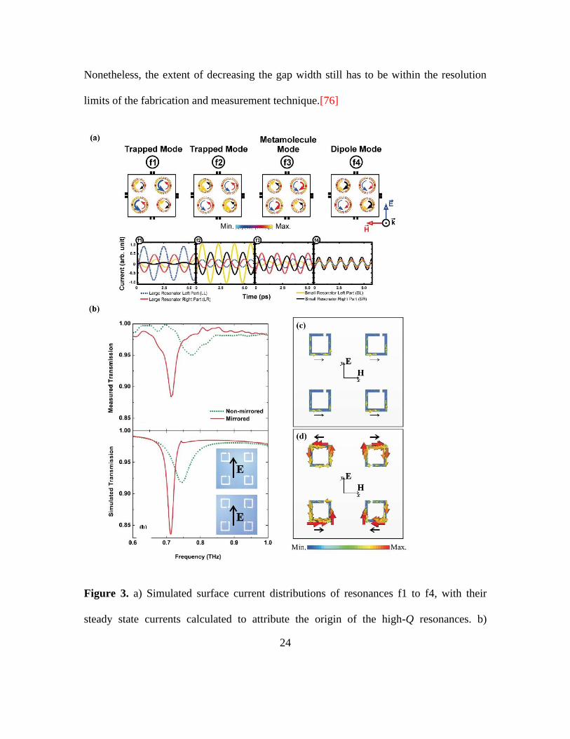
resonance.[55, 56] Lattices composed of two different sizes of SRRs placed in the
diagonal and anti-diagonal axis of the unit cell have shown to excite multiple Fano
resonances in a single plasmonic system at THz frequencies.[72] This is also applicable
to Fano resonators at other regimes of the electromagnetic spectrum.[63] Based on the
quantitative analysis of surface currents (Figure 3a), the Fano-like asymmetric lineshape
of trapped mode f1 and f2 correspond to the resonance mode driven in the larger SRRs
and smaller SRRs respectively. At resonance f3, it is a Fano-like lattice mode derived
from collective excitation of both SRRs at the lattice mode. The coupling of the
resonance f3 with lattice mode brings about the third sharp asymmetric lineshape which
has a high-Q double that of resonance f1 and f2.[74] Mirrored configuration of
asymmetric SRRs could also lead to an excitation of a higher-Q subradiant resonance
mode. In a super cell composed of 4 unit cells, antiparallel surface currents that flow
opposite to each other in the neighbouring SRRs lead to effective cancellation of dipole
moment and reduces the scattered field as illustrated in Figure 3b, c. A narrow full-width
at half maximum (FWHM) bandwidth of 29 GHz was obtained in the THz range, which
gives a Q-factor that is 3 times more than the non-mirrored configurations.[75] Along
with considering the orientation or positioning of the unit cells arranged in a lattice, the
geometrical aspect of the SRRs was also explored. As it has been proven, when the gap
width decreases, it results in a narrower and sharper asymmetric linewidth where the Q-
factors obtained both theoretically and experimentally are 106 and 51 (improved by a
factor of about 3 when the gap width is reduced by a factor of 2), respectively.
24
Nonetheless, the extent of decreasing the gap width still has to be within the resolution
limits of the fabrication and measurement technique.[76]
Figure 3. a) Simulated surface current distributions of resonances f1 to f4, with their
steady state currents calculated to attribute the origin of the high-Q resonances. b)
25
Measured and simulated transmission spectra of the non-mirrored and mirrored
configuration. c) Simulated surface current distributions for both configurations, with
stronger distribution in the non-mirrored configuration.
4. Applications
Fano resonance as a type of resonant scattering phenomenon is ideal for preserving
energy in the plasmonic system since self-cancellation of dipole moments caused by
antiparallel induced currents dramatically reduce the radiative losses. Consequently,
several of the proposed unit cell designs have been adopted as part of the strategies for
the realization of a wide variety of applications that can provide solutions to overcome
challenges and limitations in the current technologies. They have been developed in
passive or active control applications such as sensors, surface-enhanced infrared
absorption, lasing spaser and optical switch, which will be reviewed accordingly.
Sensing based on Fano Resonant Metamaterials
In plasmonic sensors, detection of weak signals coming from the analyte is strongly
elevated due to the presence of electromagnetic field enhancement which is supported by
surface plasmon resonance located at the interface of metal and dielectric.[77, 78]
However, another class of sensors based on Fano resonances in plasmonics has also seen
an impressive rise in the sensing community. At Fano resonance frequency, high resonant
26
field can be confined at regions of gaps or along the edges of the planar structures. Any
pertubations that are introduced into their local environment disturbs the sensitive nature
of the resonant field. This enables the slightest detection or sensing of the variations near
the vicinity of the field. As such, Fano sensors utilize the unique scattering phenomenon
of Fano resonance that possesses not only intense confinement of electromagnetic field,
but also the high Q asymmetric lineshapes that are pivotal in making sensors with better
sensitivity and selectivity.
As one of the prominent structure that was conceived in the early stage of metamaterials,
[79] SRRs have played significant role in THz sensing. For an asymmetric THz SRRs
that is equipped with a relatively high-Q of 65 for quadrupole and 28 for Fano resonances,
a superior analyte sensitivity of 5.7 × 10⁴ nm/refractive index unit (RIU) was achieved
for Fano resonance compared to the quadrupole resonance with sensitivity of 7.75 × 10³
nm/RIU.[80] Hypothetically, the higher the Q factor of the metamaterial, the longer the
photon lifetime and light-matter interactions should be greatly enhanced. Simulated
electric field distributions of the quadrupole, dipoles and Fano resonances reveal that the
tightly confined fields at the Fano resonance frequency is much stronger than the
quadrupole and dipole resonances whose electric field enhancements are spread across
four nodes at the arms and two nodes in each arm of the SRRs respectively, as shown in
Figure 4a-d. Therefore, given the high field confinement in the small spatial volume of
the capacitive split gaps, Fano resonance has the upper hand and a significantly higher
analyte thickness sensitivity as compared to the quadrupole resonance is obtained. In
addition, when the refractive index of the analyte is varied from n =1 to n = 1.6, the Fano
27
resonance shows a sensitivity of 4.23 × 10⁴ nm/RIU while the quadrupole resonance had
a sensitivity of 5.62 × 10³ nm/RIU. The results affirm Fano resonance as a good
candidate for achieving highly sensitive refractive index sensing capabilities, even at
other regimes of the electromagnetic spectrum.[33, 34, 62] It was further reported that a
thinner substrate would promote a greater sensitivity using such high-Q resonances as it
allows for a stronger interaction between the intense field and the analyte.[55, 80, 81]
With another two split gaps imposed onto the adjacent arms of the already asymmetric
SRRs, Fano resonance and quadrupole resonance can be excited simultaneously which
could be utilised for thickness sensing and also serves as a double referencing for
increasing the accuracy of the sensitivity results.[81] Recently, Y. K. Srivastava et. al
have demonstrated dual-surface sensing based on a flexible platform suggesting the
possibilities of incorporating sensor devices onto non-uniform surfaces.[82] The results
presented is consistent with the use of an ultrathin substrate for improved sensing
capabilities[55] and to increase the amount of fringing electromagnetic fields accessible
on either sides of the substrate. Compared to previous works,[80] the use of the underside
of the substrate for sensing contributes to an additional red shift of the Fano resonance
frequency by 6 GHz, which amounts to a total red shift of Fano resonance frequency by
89 GHz for a 100 nm thick germanium deposited onto a low refractive index substrate of
25 µm thickness. These results clearly demonstrate the advantages of using dual surfaces
of the substrate as the overall sensitivity of the analyte can be increased. In addition, a
thin substrate with low refractive index also shows enhancement in thin-film sensitivity
when it comes to detecting small volume of biomolecules.

28
So far, Fano sensors have been explored for its improved sensitivity towards different
refractive indices of analytes. In a more advanced senario, these sensors can be used to
differentiate between a target molecule and its group of molecules.[83, 84] Such Fano
sensors have been achieved in the mid-infrared regime, whereby a modified dolmen
structure comprised of the monomer adjoined to one slab of the dimer is used as
illustrated in Figure 4e.[69] In this system, Fano resonance is excited for electric field
polarized parallel to the dimers. When the Fano resonance is far from the vibrational
modes of the amide, it yields information about the thickness of the protein molecules
with an accuracy difference of 0.1 nm between theoretical and experimental results. If the
Fano resonance matches with the vibrational modes of the proteins, strong interaction
between the proteins and the asymmetric dolemen structure enhances the amplitude of the
vibrational modes which provides indications of the protein's secondary structure and
orientation. This is important because ascertaining the orientation or conformational state
of the protein molecules helps to find suitable biotarget for functional availability.
Complementary Fano resonant structures of coupled annular and rectangular aperture
have shown tremendous high-Q Fano resonance of 79 (simulated) and 38 (experimental),
which were excited based on whispering gallery approach in the near-infrared
frequencies.[85] The high-Q Fano resonators exhibit spectrally tunable single and
multiple Fano resonances by changing the polarization of the incident light. The
realization of such high-Q Fano resonance is a feat, and as a proof-of-concept, the Fano
resonators (with a modified geometrical structure – inclusion of multiple concentric ring
apertures) as shown in Figure 4f have demonstrated ultrasensitive detection of molecular

29
vibrational modes of poly(methyl methacrylate) (PMMA) using surface-enhanced
infrared absorption spectroscopy (SEIRA).[86] When the position of the Fano resonance
spectrally aligns with the vibrational modes of C-O-C and C-H; -CH2 and -CH3; and
C=O; spectral fingerprints that were absent in the reference spectra are precisely
identified from the amplified spectra. By using the whispering-gallery-mode-based Fano
resonators, weak signals of ultrathin PMMA (50 nm thickness) are enhanced, overcoming
the limitation imposed by the exponentially decreasing absorption as thickness decreases.
Figure 4. Simulated electric field distribution of a) quadrupole and b,c) two different
dipoles under horizontal polarization, d) Fano resonance under vertical polarization,
without and with an analyte above the asymmetric THz SRRs. Schematic diagrams of the
e) modified dolmen structure used in the identification of vibrational modes of protein
30
molecules and f) coupled annular and rectangular apertures used in the SEIRA of PMMA
(inset shows the different metasurfaces used to excite multiple Fano resonances).
Lasing spaser
Light amplification by stimulated emission of radiation (LASER), has been widely used
in optical systems for broad applications in telecommunications, health technology,
military defence, research industry and other commercial purposes. With miniaturization
of devices being a trend in the modern world, it is a challenge to fit a laser into nanoscale
devices. Bergman and Stockman first proposed the concept of surface plasmon
amplification by stimulated emission of radiation (SPASER) in 2003, which suggests that
surface plasmons can be used to confine and concentrate optical energy into dimensions
smaller than a wavelength, beating the diffraction limit of light.[87] A spaser works on
the principle similar to a laser, but with a resonant cavity made up of its nanoparticle and
emits surface plasmons. By introducing a gain medium into the spaser, self-sustaining
stimulated amplification occurs within whereby energy is transferred between the
luminescence resonance of the gain medium and the surface plasmon modes, thus
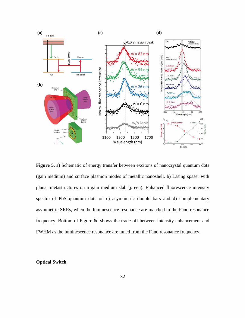
stimulating more identical surface plasmons as illustrated in Figure 5a.[88] A high-Q
resonance is preferred for its ability to sustain both phase and energy when subjected to
external electromagnetic field, in which an ideal choice would be Fano resonance. N.
Zheludev and his group proposed the combination of strong coherent planar
metastructures with a gain material to generate spatially and temporally confined
31
coherent electromagnetic radiation (Figure 5b).[89] It was theorectically demonstrated
using asymmetric SRRs which exhibits reduction of radiation losses in an infinite
periodic array.[56] Therefore, if a high-Q Fano resonance is employed with a gain
material, losses can be sufficiently overcome to the extent that the minimum condition set
by the lasing threshold of the plasmonic system can be met for lasing action to occur,
hence successfully realising a lasing spaser at nanoscale dimensions. As a first step, lead
sulphide (PbS) semiconductor quantum dots were spin coated onto asymmetric SRRs
array. The Fano resonance was designed such that it matches exactly at the luminescence
resonance of the quantum dots and strong coupling between the excitons and plasmon
modes leads to multifold enhancement of the quantum dot luminescence and spectral
narrowing of the linewidth as shown in Figure 5c,d.[64, 90] Till date, there is no
demonstration of a planar lasing spaser based on Fano resonance due to the requirement
of high pumping power which generates excessive heat losses in plasmonic
metamaterials.
32
Figure 5. a) Schematic of energy transfer between excitons of nanocrystal quantum dots
(gain medium) and surface plasmon modes of metallic nanoshell. b) Lasing spaser with
planar metastructures on a gain medium slab (green). Enhanced fluorescence intensity
spectra of PbS quantum dots on c) asymmetric double bars and d) complementary
asymmetric SRRs, when the luminescence resonance are matched to the Fano resonance
frequency. Bottom of Figure 6d shows the trade-off between intensity enhancement and
FWHM as the luminescence resonance are tuned from the Fano resonance frequency.
Optical Switch

33
One of the key strengths of Fano resonance is the sensitive nature of the intense
electromagnetic field present in the planar structures. As a result, it could be used for
purposes where external influences can be introduced to realise more functionalities of
the Fano devices. Active photoswitching of Fano resonance has been demonstrated by R.
Singh and his group using optically active medium such as solution-processed
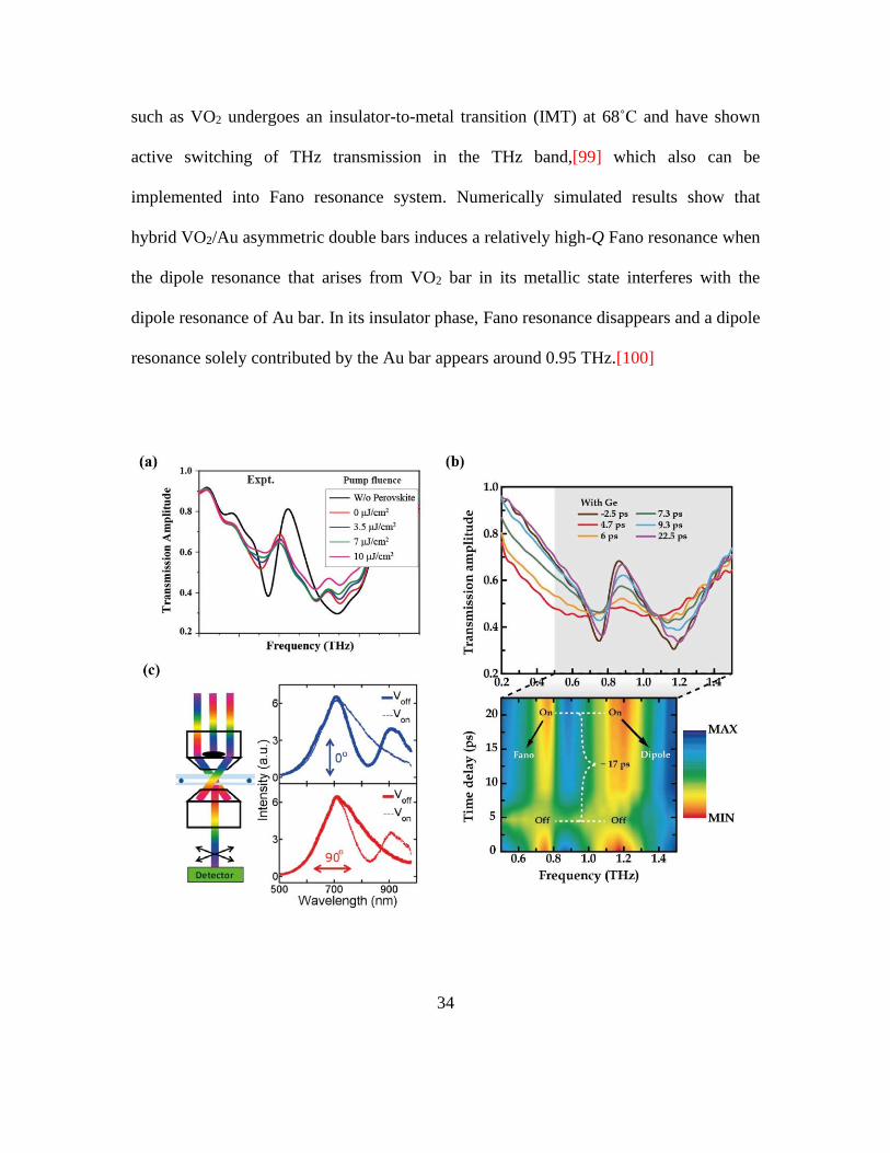
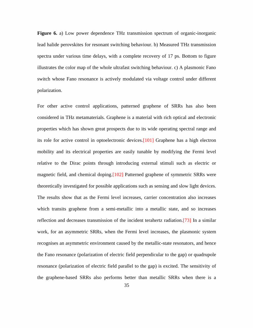
perovskites,[91, 92] silicon,[93] germanium,[94] and MoS2[95] in asymmetric SRRs. An
ultralow fluence of <7 µJ cm-2 of the optical pump beam is required for resonant
switching behaviour in organic-inorganic lead halide perovskites as shown in Figure 6a.
Upon increasing optical excitation fluence, the metadevice manifests phonon-Fano
coupling which shows the sensitive nature of Fano resonance to detection of the phonon
modes.[92] By evaporating a single-element germanium onto the asymmetric SRRs, an
ultrafast full recovery time of 17 ps was achieved (Figure 6b), comparable to the
switching time of inductive-capactive (LC) resonance using ErAs/GaAs superlattice
structures.[96, 97] Such approach is simple and universally applicable to other
metadevices, and the results also show that Fano resonance as compared to other
resonances is more sensitive to optical switching.[94] Another approach to active
switching is via applying a voltage onto a liquid crystal to change the phase of the
medium, which alters the polarization of the incident light propagating through and
excites the symmetry-broken octamer structure to reveal the Fano resonance. Hence, the
switching on and off of the voltage indirectly excites the octamer structure with different
polarization of incident light, realizing an electrically switchable Fano switch in the
visible spectrum as shown in Figure 6c.[98] In addition, phase-transition metal oxide
34
such as VO2 undergoes an insulator-to-metal transition (IMT) at 68˚C and have shown
active switching of THz transmission in the THz band,[99] which also can be
implemented into Fano resonance system. Numerically simulated results show that
hybrid VO2/Au asymmetric double bars induces a relatively high-Q Fano resonance when
the dipole resonance that arises from VO2 bar in its metallic state interferes with the
dipole resonance of Au bar. In its insulator phase, Fano resonance disappears and a dipole
resonance solely contributed by the Au bar appears around 0.95 THz.[100]
35
Figure 6. a) Low power dependence THz transmission spectrum of organic-inorganic
lead halide perovskites for resonant switching behaviour. b) Measured THz transmission
spectra under various time delays, with a complete recovery of 17 ps. Bottom to figure
illustrates the color map of the whole ultrafast switching behaviour. c) A plasmonic Fano
switch whose Fano resonance is actively modulated via voltage control under different
polarization.
For other active control applications, patterned graphene of SRRs has also been
considered in THz metamaterials. Graphene is a material with rich optical and electronic
properties which has shown great prospects due to its wide operating spectral range and
its role for active control in optoelectronic devices.[101] Graphene has a high electron
mobility and its electrical properties are easily tunable by modifying the Fermi level
relative to the Dirac points through introducing external stimuli such as electric or
magnetic field, and chemical doping.[102] Patterned graphene of symmetric SRRs were
theoretically investigated for possible applications such as sensing and slow light devices.
The results show that as the Fermi level increases, carrier concentration also increases
which transits graphene from a semi-metallic into a metallic state, and so increases
reflection and decreases transmission of the incident terahertz radiation.[73] In a similar
work, for an asymmetric SRRs, when the Fermi level increases, the plasmonic system
recognises an asymmetric environment caused by the metallic-state resonators, and hence
the Fano resonance (polarization of electric field perpendicular to the gap) or quadrupole
resonance (polarization of electric field parallel to the gap) is excited. The sensitivity of
the graphene-based SRRs also performs better than metallic SRRs when there is a

36
variation of refractive index or thickness of analyte.[80] For both resonances excited, the
effective group index is at least 30 times larger than a metal plasmonic system, promising
as a potential candidate for slow light applications.[73] In the infrared regime, by
combining single-layer graphene (SLG) with high-Q Fano metasurfaces made up of an
array of wire and SRR structures, two Fano resonances with a reflectivity dips were
observed in the spectrum. An electrostatic potential applied between the SLG and Si
backgate controls the free carrier density in graphene which can potentially blue-shift the
Fano resonance spectrum with increasing Fermi energy. Similar observation was seen in
another numerical study of a hybrid graphene disk and metallic ring system which has
been proposed to realise tunable terahertz sensor.[103] Overall, the change in the free
carrier density results in a modulation depth of about 10 dB, thus achieving an
electrically controlled IR modulator.[104] However, dissipation losses remain a cause for
concern even if graphene is to replace metals in metamaterials.[105]
5. Perspectives to Loss-Engineering
Superconductors as resonator material
In the THz regime, non-radiative losses are reduced due to the higher conductivity of
metals, making radiative losses as the dominant loss mechanism. Therefore, Fano
resonance provides a means of reducing the losses contributed by radiation to free space.
However, to push beyond the limits of reducing non-radiative losses in planar
metastructures, superconductors as an alternative to metal permits the existence of Fano
37
resonance beyond a critical point of asymmetry parameter with an even higher Q-
factor.[106] As shown in Figure 7a, the linewidth of superconducting Fano resonators is
narrower than metallic Fano resonators. A high Q-factor of 167 was obtained using
YBCO-THz ASRRs, which is about two times the Q-factor (84) obtained using Al-THz
asymmetric SRRs. In fact, if a material such as perfect electric conductor (PEC) with zero
resistivity could exist, the ohmic losses will undoubtedly disappear, and a higher Q-factor
can be obtained as compared to metal or superconductor, as depicted in Figure 7b. This
suggests that for an entirely hypothetical material, the maximum value of attainable Q-
factor for Fano resonance is purely restricted by radiative losses.[107] Nevertheless, the
use of superconductors is a more practical solution and would suffice for accessing the
high Q-factor Fano resonance at low asymmetry regimes.
Unfortunately, superconductors are only accessible at the terahertz or lower frequency
regime because at higher frequencies, the incident photon could break the binding energy
of Cooper pairs in superconductors, hence disabling the superconductivity
properties.[108] As a consequence, there have to be other alternatives to further increase
the Q-factor of Fano resonance. We look at possible alternatives to reduce radiative
losses in planar metallic metamaterials.
Manipulating configuration
Realistically, metals are still the preferred choice of material for exciting Fano resonance
in metamaterials as superconductivity only works under low temperature condition.
38
Therefore, alternative solution to enhance the Q-factor of Fano resonance has to be
established. An approach would be to manipulate the configuration of unit cells in the
metamaterial array to mitigate radiative losses. It was reported that by alternating[109] or
inverting[110] an asymmetric dipole bars (which constitute to one of two sub-unit cells)
and placing it adjacent to neighbouring asymmetric dipole bars, an enhancement in the
Q-factor of Fano resonance can be achieved. Based on the schematic of dipole-dipole
interference, an enhancement in the Q-factor of Fano resonance in an alternating unit cell
configuration was ascribed to destructive interference of dipole moments contributed by
neighbouring sub-unit cells as illustrated in Figure 7c. As a result, the net dipole moment
of the alternating unit cell configuration is smaller than the non-alternating unit cell
configuration. Therefore, the radiative loss in an alternating unit cell configuration is
much lower which establishes a higher Q-factor.[109] Quantitative analysis of
complementary asymmetric double bars using multipole decomposition reveals that the
linewidth narrowing of resonance in an inverted unit cell configurations is due to the
competition between magnetic quadrupole and toroidol dipole. In this case, the magnetic
quadrupole serves to narrow the resonance linewidth, while the toroidal dipole broadens
the resonance linewidth.[110]
Toroidal dipole has been actively studied using planar asymmetric SRRs, whereby two
asymmetric SRRs that individually produces Fano resonance are placed in a mirroring
configuration.[111, 112, 113, 114, 115] Each Fano resonance in an asymmetric SRRs has
a magnetic dipole moment that points perpendicular to the plane of the metasurface. In a
mirrored configuration, the anti-parallel magnetic dipole moments of both asymmetric

39
SRRs form a head-to-tail alignment, hence introducing a magnetic toroidal dipole into the
Fano system (Figure 7d). A comparison between the toroidal and Fano resonances shows
that a higher Q-factor can be obtained in a mirroring configuration of asymmetric SRRs.
In this instance, multipole analysis further affirms that the narrow linewidth and
enhanced Q-factor in the planar metamaterial system is attributed to the newly generated
toroidal dipole resonance.[113, 114] Toroidal resonance boasts a stronger localization of
electromagnetic fields and lesser radiative loss as compared to Fano resonance. Thus, it
has already shown substantial promises in future applications such as sensor,[116]
photoswitch[117] and lasing[118] devices.
Dielectrics as resonator material
All-dielectric planar Fano structures represent a highly feasible and efficient way of
reducing both radiative and non-radiative losses. In particular, low-loss and high
refractive index dielectric materials can address the problems of non-radiative losses
faced in most metallic planar metamaterials as absorption in metallic systems is
unavoidable. The huge dissipation loss is inherent in metals,[119] especially at visible
and infrared regimes.[120] Fano resonance in all-dielectrics have been demonstrated in
asymmetric double bars,[121, 122] oligomers,[123] dolmen structures,[124] and coupled
rectangular and ring resonators.[125] Furthermore, the suppression of radiative losses is
also reliant on the collective and coherent oscillations of the resonators in the array.[125,
126] In contrast, electromagnetic fields are concentrated within the dielectric

40
nanostructures, whereas in plasmonic nanostructures the separation between the
resonators reduces the localized field confinement at the gaps, which suggests that
dielectric metamaterials are insensitive to geometrical imperfections in the unit cell.[122]
All-dielectrics offer other advantages over plasmonic metamaterials such as lower ohmic
losses, robustness in the position of the Fano resonance frequency (Figure 7e),[123] and
larger damage threshold for nonlinear effects. [127] Using Si-based metasurfaces, EIT
effects with high Q-factor of 483 has been realized for refractive index sensing, hence
achieving a high figure-of-merit of 103.[125] Fano resonance in chiral Si metasurfaces
(Q > 100) has achieved high (50%) linear-to-circular polarization conversion efficiency
and shown great potential in spectroscopic characterization of single-layer graphene or
protein monolayers (with at least 40% transmission change) without the need of highly
focused infrared light source. [124] An array of coupled rectangular and nanodisk
resonators with a high Q-factor of 466 has demonstrated third harmonic generation
(THG) enhancement of at least 105 owing to the good modal overlap with Si medium,
hence achieving a conversion efficiency of 10-6 using a peak pump intensity of 3.2 GW
cm-2 (Figure 7f).[127] Recently, a record high Q-factor of 1011 has enabled
photoluminscence enhancement of 103 at the peak MM1 position in an asymmetric air hole
configuration that is composed of semicircle and semiellipse, embedded with germanium
(Ge) quantum dots (Figure 7g).[128] All-dielectrics is a feasible replacement to the
plasmonics counterpart as it offers low-loss high-Q Fano resonances, that can be realized
for similar metamaterials-based applications. To summarize the perspectives to loss-
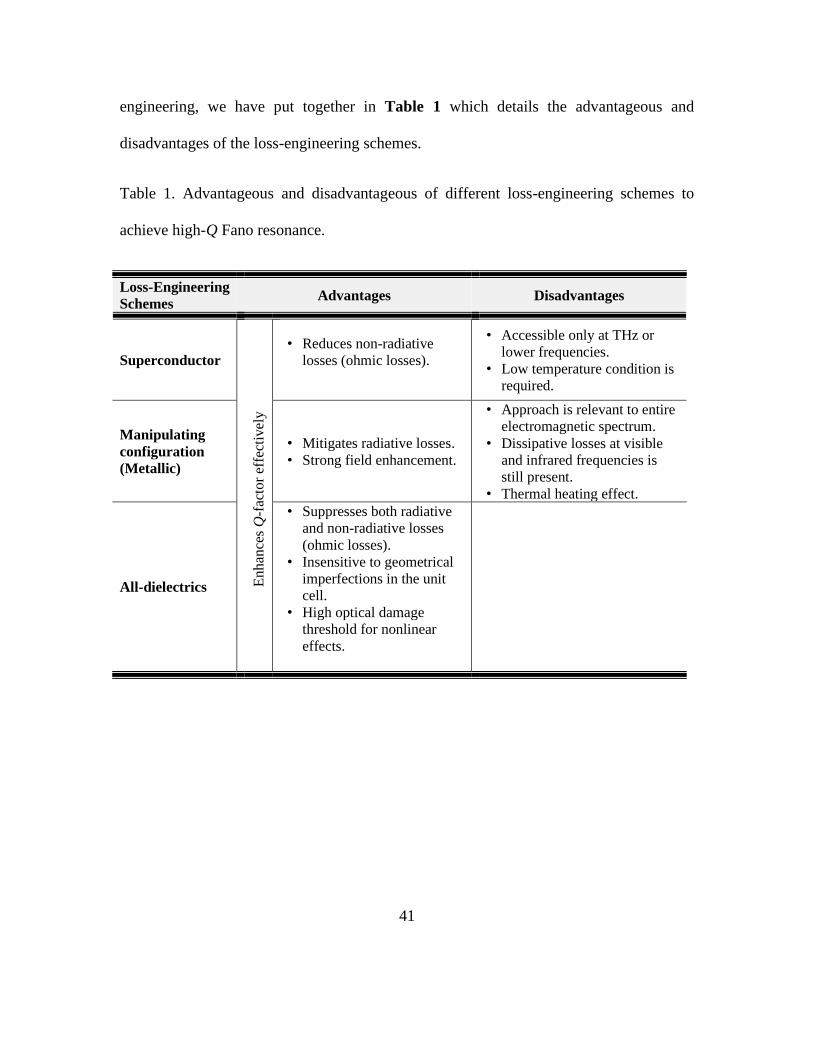
41
engineering, we have put together in Table 1 which details the advantageous and
disadvantages of the loss-engineering schemes.
Table 1. Advantageous and disadvantageous of different loss-engineering schemes to
achieve high-Q Fano resonance.
Loss-Engineering
Schemes Advantages Disadvantages
Superconductor
Enhan
ces
Q-f
acto
r ef
fect
ivel
y
• Reduces non-radiative
losses (ohmic losses).
• Accessible only at THz or
lower frequencies.
• Low temperature condition is
required.
Manipulating
configuration
(Metallic)
• Mitigates radiative losses.
• Strong field enhancement.
• Approach is relevant to entire
electromagnetic spectrum.
• Dissipative losses at visible
and infrared frequencies is
still present.
• Thermal heating effect.
All-dielectrics
• Suppresses both radiative
and non-radiative losses
(ohmic losses).
• Insensitive to geometrical
imperfections in the unit
cell.
• High optical damage
threshold for nonlinear
effects.

42
Figure 7. a) Simulated and measured transmission spectra showing comparison between
metallic and superconducting Fano resonators. b) Calculated Q-factor of PEC,
superconductor and metal. c) Scheme of dipole-dipole interference, where situations of
constructive and destructive interferences are presented. The electric fields of the
alternately (alt)-flipped configuration shows more cancellation as compared to the non
(N)-flipped configuration, which results in a smaller net dipole moment and a higher Q-

43
factor. d) Illustration of the Fano and Toroid configurations with their surface currents
inducing magnetic dipole moments that does not couple in the Fano configuration but
couple in a head-to-tail configuration (Toroid). A higher Q-factor is seen in the Toroid
configuration as compared to the Fano configuration. e) Simulated scattering cross-
section of all-dielectric (Si) oligomers and metallic (Au) oligomers, in which the Fano
resonance continues to persist despite widening the separation between the particles. (f)
Simulated electric field strength of the all-dielectric (Si) Fano resonators and the THG
intensity spectra of metasurface or unpatterned bare Si film on the bare quartz substrate.
(g) Measured transmission (dark cyan) and photoluminescence spectra of the metasurface
embedded with Ge quantum dots at 295K (blue) and 5K (magenta).
Future outlook and conclusion
In summary, we have reviewed an extensive but not exhaustive list of unit cell designs
that are suitable for lineshape engineering of Fano resonance. Fano resonance in planar
metallic structures provide an effective approach to mitigate radiative losses. Fano
resonance possesses a sharp asymmetric lineshape and an intense electromagnetic field
confinement exists at the resonance frequency. With these two distinct characteristics,
Fano resonance has caught a significant amount of attention in the metamaterial
community and enabled metadevices with remarkable functionalities to be developed.
However, non-radiative losses such as ohmic and absorption losses continue to hinder
practical applications of plasmonic metamaterials. Superconductors may be a good

44
alternative but its operating condition exists only at low temperature which makes it not
as feasible for facile applications. As the innovations in plasmonic metamaterials
continue to be explored, exploiting low-loss, high-refractive index dielectric materials is
the next viable option to consider reducing non-radiative losses. Indeed, several
applications similar to plasmonic counterparts can be realized using all-dielectrics.[53,
129] Without doubt, high-Q Fano resonance promises wide applicability in
miniaturization of a variety of optoelectronics devices including sensors, photoswitch,
and active control devices. Thus, it is not surprising to envision that Fano resonance-
based metadevices could be at the forefront of modern technologies and devices.
Supporting Information
Supporting Information is available from the Wiley Online Library or from the author.
Acknowledgement
This work is supported by research grants from Singapore Ministry of Education No.
MOE2016-T3-1-006(S) and MOE2015-T2-2-103.
Received: ((will be filled in by the editorial staff))
Revised: ((will be filled in by the editorial staff))
Published online: ((will be filled in by the editorial staff))

45

46
References:
[1] D. Hillerkuss, R. Schmogrow, T. Schellinger, M. Jordan, M. Winter, G. Huber, T.
Vallaitis, R. Bonk, P. Kleinow, F. Frey, M. Roeger, S. Koenig, A. Ludwig, A.
Marculescu, J. Li, M. Hoh, M. Dreschmann, J. Meyer, S. Ben Ezra, N. Narkiss, B.
Nebendahl, F. Parmigiani, P. Petropoulos, B. Resan, A. Oehler, K. Weingarten, T.
Ellermeyer, J. Lutz, M. Moeller, M. Huebner, J. Becker, C. Koos, W. Freude, J.
Leuthold, Nat. Photonics 2011, 5, 364.
[2] F. Li, M. Pelusi, D-X. Xu, R. Ma, S. Janz, B. J. Eggleton, D. J. Moss, Opt.
Lett. 2011, 19, 22410.
[3] W. Liu, M. Li, R. S. Guzzon, E. J. Norberg, J. S. Parker, M. Lu, L. A. Coldren, J.
Yao, Nat. Photonics 2016, 10, 190.
[4] L. Razzari, D. Duchesne, M. Ferrera, R. Morandotti, S. Chu, B. E. Little, D. J.
Moss, Nat. Photonics 2010, 4, 41.
[5] J. S. Levy, A. Gondarenko, M. A. Foster, A. C. Turner-Foster, A. L. Gaeta, M.
Lipson, Nat. Photonics 2010, 4, 37.
[6] J. Müller, F. Merget, S. Sharif Azadeh, J. Hauck, S. Romeo García, B. Shen, J.
Witzens, Sci. Rep. 2014, 4, 6310.
[7] H. Jung, K. Y. Fong, C. Xiong, and H. X. Tang, Opt. Lett. 2014, 39, 84.
47
[8] J. Pfeifle, V. Brasch, M. Lauermann, Y. Yu Yimin, D. Wegner, T. Herr, K.
Hartinger, P. Schindler, J. S. Li, D. Hillerkuss, R. Schmogrow, C. Weimann, R.
Holzwarth, W. Freude, J. Leuthold, T. J. Kippenberg, C. Koos, Nat. Photonics 2014, 8,
375.
[9] F. Vollmer, S. Arnold, Nat. Methods 2008, 5, 591.
[10] A. M. Armani, R. P. Kulkarni, S. E. Fraser, R. C. Flagan, K. J. Vahala, Science
2017, 317, 783.
[11] J. Zhu, S. K. Ozdemir, Y. F. Xiao, L. Li, L. He, D. R. Chen, L. Yang, Nat.
Photonics 2010, 4, 46.
[12] A. G. Griffith, R. K. W. Lau, J. Cardenas, Y. Okawachi, A. Mohanty, R. Fain, Y.
H. D. Lee, M. J. Yu, C. T. Phare, C. B. Poitras, A. L. Gaeta, M. Lipson, Nat.
Commun. 2015, 6, 6299.
[13] M. J. Thorpe, K. D. Moll, R. J. Jones, B. Safdi, J. Ye, Science 2006, 311, 1595.
[14] R. Shankar, I. Bulu, M. Loncar, Appl. Phys. Lett. 2013, 102, 051108.
[15] M. S. Luchansky, R. C. Bailey, Anal. Chem. 2012, 84, 793.
[16] A. M. Hawkes, A. R. Katko, S. A. Cummer, Appl. Phys. Lett. 2013, 103, 163901.
[17] O. M. Ramahi, T. S. Almoneef, M. Alshareef, M. S. Boybay, Appl. Phys. Lett.
2012, 101, 173903.
[18] T. S. Almoneef, O. M. Ramahi, Appl. Phys. Lett. 2015, 106, 153902.

48
[19] N. Zhu, R. W. Ziolkowski, H. Xin, Appl. Phys. Lett. 2011, 99, 114101.
[20] A. E. Miroshnichenko, S. Flach, Y. S. Kivshar, Rev. Mod. Phys. 2010, 82, 2257.
[21] T. Cao, L. Zhang, Z. P. Xiao, H. Huang, J. Phys. D: Appl. Phys. 2013, 46, 395103.
[22] T. Cao, C. Wei, R. E. Simpson, L. Zhang, M. J. Cryan, Sci. Rep. 2014, 4, 4463.
[23] W. X. Lim, R. Singh, Nano Convergence, 2018, 5, 1.
[24] L. Cong, M. Manjappa, N. Xu, I. Al-Naib, W. Zhang, R. Singh, Adv. Opt.
Mater. 2015, 3, 1537.
[25] B. Luk’yanchuk, N. I. Zheludev, S. A. Maier, N. J. Halas, P. Nordlander, H.
Giessen, C. T. Chong, Nat. Mater. 2010, 9, 707.
[26] E. Prodan, C. Radloff, N. J. Halas, P. Nordlander, Science 2003, 302, 419.
[27] E. Prodan, P. Nordlander, Nano Lett. 2003, 3, 543.
[28] N. Liu and H. Giessen, Angew. Chem. Int. Ed. 2010, 49, 9838.
[29] F. Hao, Y. Sonnefraud, P. Van Dorpe, S. A. Maier, N. J. Halas, P. Nordlander,
Nano Lett. 2008, 8, 3983.
[30] S. Zhang, K. Bao, N. J. Halas, H. Xu, P. Nordlander, Nano Lett. 2011, 11, 1657.
[31] N. Verellen, Y. Sonnefraud, H. Sobhani, F. Hao, V. V. Moshchalkov, P. V. Dorpe,
P. Nordlander, S. A. Maier, Nano Lett. 2009, 9, 1663.
[32] Z. Fang, J. Cai, Z. Yan, P. Nordlander, N. J. Halas, X. Zhu, Nano
Lett. 2011, 11, 4475.
49
[33] N. Verellen, P. Van Dorpe, C. Huang, K. Lodewijks, G. A. E. Vandenbosch, L.
Lagae, V. V. Moshchalkov, Nano Lett. 2011, 11, 391.
[34] Y. Sonnefraud, N. Verellen, H. Sobhani, G. A. E. Vandenbosch, V. V.
Moshchalkov, P. Van Dorpe, P. Nordlander, S. A. Maier, ACS Nano 2010, 4, 1664.
[35] N. A. Mirin, K. Bao, P. Nordlander, J. Phys. Chem. A 2009, 113, 4028.
[36] A. Lovera, B. Gallinet, P. Nordlander, O. J. Martin, ACS Nano 2013, 7, 4527.
[37] C. L. Garrido Alzar, M. A. G. Martinez, P. Nussenzveig, Am. J. Phys. 2002, 70,
37.
[38] B. Gallinet, O. J. Martin, Phys. Rev. B, 2011, 83, 235427.
[39] J. B. Lassiter, H. Sobhani, M. W. Knight, W. S. Mielczarek, P. Nordlander, N. J.
Halas, Nano Lett. 2012, 12, 1058.
[40] F.-Y. Meng, Q. Wu, D. Erni, K. Wu, J.-C. Lee, IEEE Trans. Microwave Theory
Tech. 2012, 60, 3013.
[41] M. Manjappa, S.-Yi Chiam, L. Cong, A. A. Bettiol, W. Zhang, R. Singh, Appl.
Phys. Lett. 2015, 106, 181101.
[42] N. Liu, L. Langguth, T. Weiss, J. Kästel, M. Fleischhauer, T. Pfau, H. Giessen,
Nat. Mater. 2009, 8, 758.
[43] M. Babinet, C. R. Acad. Sci. 1837, 4, 638.
[44] H. Jung, C. In, H. Choi, H. Lee, Sci. Rep. 2014, 4, 5217.

50
[45] T. Zentgraf, T. P. Meyrath, A. Seidel, S. Kaiser, H. Giessen, Phys. Rev.
B 2007, 76, 033407.
[46] F. Falcone, T. Lopetegi, M. A. G. Laso, J. D. Baena, J. Bonache, M. Beruete, R.
Marques, F. Martin, M. Sorolla, Phys. Rev. Lett. 2004, 93, 197401.
[47] A. Bitzer, H. Merbold, A. Thoman, T. Feurer, H. Helm, M. Walther, Opt. Express
2009, 17, 3826.
[48] R. Singh, I. Al-Naib, W. Cao, C. Rockstuhl, M. Koch, W. Zhang, IEEE Trans.
Terahertz Sci. Technol. 2013, 3, 820.
[49] L. Wang, X. Chen, Q. Cao, W. Tang, C. Liu, W. Lu, Plasmonics 2017, 12, 353.
[50] F. Wang, Z. Wang, J. Shi, J. Appl. Phys. 2014, 116, 153506.
[51] N. Born, I. Al-Naib, C. Jansen, R. Singh, J. V. Moloney, M. Scheller, M. Koch,
Adv. Opt. Mater. 2015, 3, 642.
[52] J. Vogt, S. Zimmermann, C. Huck, M. Tzschoppe, F. Neubrech, S. Fatikow, A.
Pucci, ACS Photonics 2017, 4, 560
[53] M. F. Limonov, M. V. Rybin, A. N. Poddubny, Y. S. Kivshar, Nat.
Photonics 2017, 11, 543.
[54] V. A. Fedotov, M. Rose, S. L. Prosvirnin, N. Papasimakis, N. I. Zheludev, Phys.
Rev. Lett. 2007, 99, 147401.
[55] Y. Chen, I. A. I. Al-Naib, J. Gu, M. Wang, T. Ozaki, R. Morandotti, W. Zhang,
AIP Adv. 2, 2012, 2, 022109.

51
[56] V. A. Fedotov, N. Papasimakis, E. Plum, A. Bitzer, M. Walther, P. Kuo, D. P.
Tsai, N. I. Zheludev, Phys. Rev. Lett. 2010, 104, 223901.
[57] W. Cao, R. Singh, I. A. I. Al-Naib, M. He, A. J. Taylor, W. Zhang, Opt. Lett.
2012, 37, 3366.
[58] Z.-G. Dong, H. Liu, M. X. Xu, T. Li, S. M. Wang, S. N. Zhu, X. Zhang, Opt.
Express 2010, 18, 18229.
[59] J. Wang, X. Liu, L. Li, J. He, C. Fan, Y. Tian, P. Ding, D. Chen, Q. Xue, E. Liang,
J. Opt. 2013, 15, 105003.
[60] F. Zhang, X. Huang, Q. Zhao, L. Chen, Y. Wang, L. Qiang, X. He, C. Li, K. Chen,
Appl. Phys. Lett. 2014, 105, 172901.
[61] Y. Moritake, Y. Kanamori, K. Hane, Opt. Lett. 2014, 39, 4057.
[62] N. E. J. Omaghali, V. Tkachenko, A. Andreone, G. Abbate, Sensors 2014, 14, 272.
[63] Y. Moritake, Y. Kanamori, K. Hane, Opt. Express 2016, 24, 9332.
[64] Y. Moritake, Y. Kanamori, K. Hane, Sci. Rep. 2016, 6, 33208.
[65] J. Shu, W. Gao, Q. Xu, Opt. Express 2013, 21, 11101.
[66] I. A. I. Al-Naib, C. Jansen, N. Born, M. Koch, Appl. Phys. Lett. 2011, 98, 091107.
[67] J. Shu, W. Gao, K. Reichel, D. Nickel, J. Dominguez, I. Brener, D. M. Mittleman,
Q. Xu, Opt. Express 2014, 22, 3747.

52
[68] N. Papasimakis, Y. Fu, V. Fedotov, S. Prosvirnin, D. Tsai, N. Zheludev, Appl.
Phys. Lett. 2009, 94, 211902.
[69] C. Wu, A. B. Khanikaev, R. Adato, N. Arju, A. A. Yanik, H. Altug, G. Shvets,
Nat. Mater. 2011, 11, 69.
[70] J. A. Fan, C. Wu, K. Bao, J. M. Bao, R. Bardhan, N. J. Halas, V. N. Manoharan, P.
Nordlander, G. Shvets, F. Capasso, Science 2010, 328, 1135.
[71] J. B. Lassiter, H. Sobhani, J. A. Fan, J. Kundu, F. Capasso, P. Nordlander, N. J.
Halas, Nano Lett. 2010, 10, 3184.
[72] N. Born, I. Al-Naib, C. Jansen, T. Ozaki, R. Morandotti, M. Koch, Appl. Phys.
Lett. 2014, 104, 101107.
[73] W. Tang, L. Wang, X. Chen, C. Liu, A. Yu, W. Lu, Nanoscale 2016, 8, 15196.
[74] N. Xu, R. Singh, W. Zhang, Appl. Phys. Lett. 2016, 109, 021108.
[75] I. Al-Naib, R. Singh, C. Rockstuhl, F. Lederer, S. Delprat, D. Rocheleau, M.
Chaker, T. Ozaki, R. Morandotti, Appl. Phys. Lett. 2012, 101, 071108.
[76] Y. P. Cao, Y. Y. Wang, Z. X. Geng, J. Liu, Y. P. Yang, H. D. Chen, J. Appl. Phys.
2015, 117, 063107.
[77] M. Li, S. K. Cushing, N. Wu, Analyst 2015, 140, 386.
[78] J. N. Anker, W. P. Hall, O. Lyandres, N. C. Shah, J. Zhao, R. P. Van Duyne, Nat.
Mater. 2008, 7, 442.
[79] D. Smith, J. Pendry, M. Wiltshire, Science 2004, 305, 788.

53
[80] R. Singh, W. Cao, I. Al-Naib, L. Cong, W. Withayachumnankul, W. Zhang, Appl.
Phys. Lett. 2014, 105, 171101.
[81] C. Ding, L. Jiang, L. Wu, R. Gao, D. Xu, G. Zhang, J. Yao, Opt. Commun., 2015,
350, 103.
[82] Y.K. Srivastava, L. Cong, R. Singh, Appl. Phys. Lett. 2017, 111, 201101.
[83] J. I. Njagi, S. M. Kagwanja, The interface in biosensing: improving selectivity
and sensitivity, ACS Symposium Series 2011, 1062 (Interfaces and Interphases in
Analytical Chemistry), 225-247.
[84] N. Liu, A. Pucci, Nat. Mater. 2012, 11, 9.
[85] G. Dayal, X. Y. Chin, C. Soci, R. Singh, Adv. Opt. Mater. 2016, 4, 1295.
[86] G. Dayal, X. Y. Chin, C. Soci, R. Singh, Adv. Opt. Mater. 2016, 5, 1600559.
[87] D. J. Bergman, M. I. Stockman, Phys. Rev. Lett. 2003, 90, 027402.
[88] M. Stockman, Nat. Photonics 2008, 2, 327.
[89] N. I. Zheludev, S. L. Prosvirnin, N. Papasimakis, V. A. Fedotov, Nat. Photonics
2008, 2, 351.
[90] K. Tanaka, E. Plum, J. Y. Ou, T. Uchino, N. I. Zheludev, Phys. Rev. Lett. 2010,
105, 227403.
[91] L. Cong, Y.K. Srivastava, A. Solanki, T.C. Sum, R. Singh, ACS Photonics 2017,
4, 1595.

54
[92] M. Manjappa, Y. K. Srivastava, A. Solanki, A. Kumar, T. C. Sum, R. Singh, Adv.
Mater. 2017, 29, 1605881.
[93] M. Manjappa, Y.K. Srivastava, L. Cong, I. Al-Naib, R. Singh, Adv. Mater. 2017,
29, 1603355.
[94] W.X. Lim, M. Manjappa, Y.K. Srivastava, L. Cong, A. Kumar, K.F. MacDonald,
R. Singh, Adv. Mater. 2018, 1705331.
[95] Y.K. Srivastava, A. Chaturvedi, M. Manjappa, A. Kumar, G. Dayal, C. Kloc, R.
Singh, Adv. Opt. Mater. 2017, 5, 1700762.
[96] H.-T. Chen, W. J. Padilla, J. M. O. Zide, S. R. Bank, A. C. Gossard, A. J. Taylor,
R. D. Averitt, Opt. Lett. 2007, 32, 1620.
[97] A. K. Azad, H. T. Chen, S. R. Kasarla, A. J. Taylor, Z. Tian, X. C. Lu, W. Zhang,
H. Lu, A. C. Gossard, J. F. O’Hara, Appl. Phys. Lett. 2009, 95, 011105.
[98] W.-S. Chang, J. B. Lassiter, P. Swanglap, H. Sobhani, S. Khatua, P. Nordlander,
N. J. Halas, S. Link, Nano Lett. 2012, 12, 4977.
[99] Y. G. Jeong, S. Han, J. Rhie, J. S. Kyoung, J. W. Choi, N. Park, S. Hong, B. J.
Kim, H. T. Kim, D. S. Kim, Nano Lett. 2015, 15, 6318.
[100] S. Wang, L. Kang, D. H. Werner, Sci. Rep. 2017, 7, 4326.
[101] F. Bonaccorso, Z. Sun, T. Hasan, A. C. Ferrari, Nat. Photonics 2010, 4, 611.

55
[102] A. D. Boardman, V. V. Grimalsky, Y. S. Kivshar, S. V. Koshevaya, M. Lapine, N.
M. Litchinitser, V. N. Malnev, M. Noginov, Y. G. Rapoport, V. M. Shalaev, Laser
Photon. Rev. 2011, 5, 287.
[103] Y. Zhang, T. Li, B. Zeng, H. Zhang, H. Lv, X. Huang, W. Zhang, A. Azad,
Nanoscale 2015, 7, 12682.
[104] N. Dabidian, I. Kholmanov, A. B. Khanikaev, K. Tatar, S. Trendafilov, S. H.
Mousavi, C. Magnuson, R. S. Ruoff, G. Shvets, ACS Photonics, 2015, 2, 216.
[105] P. Tassin, T. Koschny, C. M. Soukoulis, Science 2013, 341, 620.
[106] Y. K. Srivastava, M. Manjappa, H. N. Krishnamoorthy, R. Singh, Adv. Opt. Mater.
2016, 4, 1875.
[107] Y. K. Srivastava, R. Singh, J. Appl. Phys. 2017, 122, 183104.
[108] R. Singh, N. Zheludev, Nat. Photonics 2014, 8, 679.
[109] Y. Moritake, Y. Kanamori, K. Hane, Appl. Phys. Lett. 2015, 107, 211108.
[110] W.X. Lim, S. Han, M. Gupta, K.F. MacDonald, R. Singh, Appl. Phys. Lett. 2017,
111, 061104.
[111] Y. Fan, Z. Wei, H. Li, H. Chen, C. M. Soukoulis, Phys. Rev. B 2013, 87, 115417.
[112] M. Gupta, V. Savinov, N. Xu, L. Cong, G. Dayal, S. Wang, W. Zhang, N. I.
Zheludev, R. Singh, Adv. Mater. 2016, 28, 8206.
[113] M. Gupta, R. Singh, Adv. Opt. Mater. 2016, 4, 2119.

56
[114] S. Han, M. Gupta, L. Cong, Y. K. Srivastava, R. Singh, J. Appl. Phys. 2017, 122,
113105.
[115] L. Cong, Y. K. Srivastava, R. Singh, Appl. Phys. Lett. 2017, 111, 081108.
[116] M. Gupta, Y. K. Srivastava, M. Manjappa, R. Singh, Appl. Phys. Lett. 2017, 110,
121108.
[117] M. Gupta, Y. K. Srivastava, R. Singh, Adv. Mater. 2017, 30, 1704845.
[118] Y.-W. Huang, W. T. Chen, P. C. Wu, V. A. Fedotov, N. I. Zheludev, D. P.
Tsai, Sci. Rep. 2013, 3, 1237.
[119] W. Y. Zhao, X. D. Leng, Y. Y. Jiang, Opt. Express 2015, 23, 6858.
[120] A. Boltasseva, H. A. Atwater, Science 2011, 331, 290.
[121] V. V. Khardikov, E. O. Larko, S. L. Prosvirnin, J. Opt. 2012, 14, 035103.
[122] J. Zhang, K. F. MacDonald, N. I. Zheludev, Opt. Express 2013, 21, 26721.
[123] A. E. Miroshnichenko, Y. S. Kivshar, Nano Lett. 2012, 12, 6459.
[124] C. Wu, N. Arju, G. Kelp, J. A. Fan, J. Dominguez, E. Gonzales, E. Tutuc, I.
Brener, G. Shvets, Nat. Commun. 2014, 5, 3892.
[125] Y. Yang, I. I. Kravchenko, D. P. Briggs, J. Valentine, Nat. Commun. 2014, 5,
5753.
[126] S. Campione, S. Liu, L. Basilio, L. Warne, W. Langston, T. S. Luk, J. Wendt, J.
Reno, G. Keeler, I. Brenner, M. Sinclair, ACS Photonics 2016, 3, 2362.

57
[127] Y. Yang, W. Wang, A. Boulesbaa, I. I. Kravchenko, D. P. Briggs, A. Puretzky, D.
Geohegan, J. Valentine, Nano Lett. 2015, 15, 7388.
[128] S. Yuan, X. Qiu, C. Cui, L. Zhu, Y. Wang, Y. Li, J. Song, Q. Huang, J. Xia, ACS
Nano 2017, 11, 10704.
[129] S. Jahani, Z. Jacob, Nat. Nanotechnol. 2016, 11, 23.