Embed Size (px)
Citation preview
Shape Memory Alloy Expandable
Pedicle Screw to Enhance Fixation in
Osteoporotic Bone: Primary Design
and Finite Element Simulation
Majid Tabesh
Vijay Goel
Mohammad H. Elahinia1
Dynamic and Smart Systems Laboratory,
Engineering Center for Orthopedic Research Excellence,
University of Toledo,
2801 West Bancroft,
Toledo, Ohio, 43606
The properties of shape memory alloys, specifically the equia-tomic intermetallic NiTi, are unique and significant in that theyoffer simple and effective solutions for some of the biomechanicalissues encountered in orthopedics. Pedicle screws, used as ananchoring point for the implantation of spinal instrumentations inthe spinal fracture and deformity treatments, entail the majordrawback of loosening and backing out in osteoporotic bone. Thestrength of the screw contact with the surrounding bone dimin-ishes as the bone degrades due to osteoporosis. The SMArtTM ped-icle screw design is developed to address the existing issue indegraded bone. It is based on the interaction of bi-stable shapememory-superelastic elements. The bi-stable assembly acts antag-onistically and consists of an external superelastic tube thatexpands the design protrusions when body temperature isattained; also an internal shape memory wire, inserted into thetube, retracts the assembly while locally heated to above the bodytemperature. This innovative bi-stable solution augments the pull-out resistance while still allowing for screw removal. The antago-nistic wire-tube assembly was evaluated and parametrically ana-lyzed as for the interaction of the superelastic tube and shapememory wire using a finite element model developed in COMSOLMultiphysicsVR . The outcomes of the simulation suggest that shapememory NiTi inserts on the SMArtTM pedicle screw can achievethe desired antagonistic functionality of expansion and retraction.Consequently, a parametric analysis was conducted over theeffect of different sizes of wires and tubes. The dimensions for thefirst sample of this innovative pedicle screw were determinedbased on the results of this analysis. [DOI: 10.1115/1.4007179]
1 Introduction
Shape memory alloys (SMAs) are a class of smart materialsthat undergo phase transformation from martensite to austeniteand vice versa in response to a change of temperature or the appli-cation of stress. The shape memory effect and superelasticity,which occur as a result of this phase transformation, are theunique properties of these alloys. The shape memory effect is therecovery of apparently permanent deformations by raising thetemperature of the material. Superelasticity is the nonlinear recov-erable loading-unloading behavior of these alloys that can occurbeyond the elastic limit of conventional metals [1,2].
Over the past 40 years shape memory alloys (SMAs) have beenused for a variety of medical applications. These applications canbe divided into two general categories: active and passive. In
active applications the temperature of the material is controlled toinduce phase transformation between austenite and martensite,which results in the desired thermomechanical behavior. As anexample, by heating the SMA elements in an active endoscope,the device bends in the desired direction. The shape memory andsuperelasticity effects allow alloys such as Nickel-Titanium(NiTi; Nitinol) to undergo large mechanically induced deforma-tions and consequently to recover the original shape. An exampleof passive use of SMAs is a coronary stent expanding inside theblood vessel due to body heat [3,4].
The second section of this paper reviews the orthopedic appli-cations of the NiTi shape memory alloys. The following sectiondeals with the shortcomings of the conventional pedicle screws inosteoporotic bone and presents the design of a novel bi-stableSMA implant, the SMArtTM pedicle screw. The implant can com-pensate for bone loss due to osteoporosis and can be removed eas-ily as needed. The latter functionality is a departure from theexisting solutions that tend to strengthen the bone-implant inter-face but at the same time make the implant removal extremelychallenging. The later sections are allocated to the finite elementsimulation of the behavior of the pedicle screw using a modelingframework for shape memory alloys developed in COMSOL Mul-tiphysics
VR
. An approximated experimental evaluation of theimplant-bone engagement is also presented.
2 Orthopedic Applications of Niti Shape
Memory Alloys
Due to superelasticity (SE), shape memory effect (SM), highdamping capacity, corrosion resistance, and biocompatibility NiTishape memory alloys (SMAs) have gained researchers’ attentionfor implementation in biomedical fields especially orthopedics.The shape memory effect can be employed to activate medicaldevices in an operation either through body heat or throughanother external heat source. Such designs could not be realizedwith conventional alloys. Superelasticity-based applications, ingeneral, take advantage of either the possibility of recoveringlarge deformations (up to 8%) or the existence of a transformationstress plateau which provides a nearly constant stress over signifi-cant strain intervals.
NiTi alloys have been implemented in various orthopedic appli-cations such as compression staples/clamps for the treatment ofbone fractures [5–17], anterior fusion of the spine [18–21], intra-medullary nails that are used to apply controlled forces to thebone [22], fixator systems for suturing tissue in minimally inva-sive surgery [23], as well as fixation bone plates [24,25], and rodsfor the treatment of scoliosis [23,26–30].
In these applications, the martensite start transformation tem-perature is typically set between 4–7 �C which can usually beattained in the device by immersion in a sterile ice-cold saline so-lution [6]. NiTi in this phase is soft and malleable and thereforethe device can be easily deformed (up to 6–8%). The recovery, oraustenite start temperature, above which the original shape will berestored, is normally chosen around 37 �C.
3 Pedicle Screws in Osteoporotic Bone
Metabolic bone diseases such as osteoporosis, osteomalacia,and Paget’s disease are usually linked with osteoporotic bone or asoft skeleton, especially in elderly patients. Due to its wide preva-lence and its associated costs, osteoporosis has received a greatdeal of attention over the past decades. Approximately 30% of post-menopausal Caucasian women in the United States have osteoporo-sis and 16% have osteoporosis of the lumbar spine. The cost of thiswas approximately $746 million in 1995 [31]. The surgical treat-ment of deformities such as kyphosis and scoliosis in the elderlycan be very challenging considering the poor bone quality and like-lihood of instrumentation displacement in these patients.
Several advances in instrumentations such as the use of laminarfixation, multisegment fixation, limited correction of the defor-mity, avoiding ending the instrumentation within the kyphotic
1Corresponding author.Manuscript received May 15, 2010; final manuscript received July 5, 2012;
published online August 20, 2012. Assoc. Editor: Ming-Yih Lee.
Journal of Medical Devices SEPTEMBER 2012, Vol. 6 / 034501-1Copyright VC 2012 by ASME
Downloaded 11 Sep 2012 to 128.194.7.34. Redistribution subject to ASME license or copyright; see http://www.asme.org/terms/Terms_Use.cfm
segments, and augmentation of the pedicle screw purchasethrough biologic and nonbiologic fillers have been accordinglydeveloped [31–34].
Bone screws have been used in spinal fixation since the mid1940s. Boucher reportedly was the first to implant pedicle screwsand Roy-Camille was the first to connect pedicle screws to a pos-terior plate. Later bone screw pioneers include Harrington, Cotrel,and Dubousset [35]. Pedicle screws are standard in posterior fixa-tion procedures (Fig. 1) for the treatment of spinal instabilitycaused by deformity, degenerative disc disease, fracture, spinalstenosis, spondylolisthesis, or tumors. However, implanting pedi-cle screws in patients with osteoporosis presents surgeons with achallenge: the loss of purchase or the grip between the bone andscrew interface leading to hardware pull-out or loosening whichmay occur during surgery, during manipulation of the instrumen-tation, or at a time after the surgery. If the screw loosening occurslate after the surgery, depending on the case, two approaches maybe taken; either revision of the instrumentation or supplementationwith an anterior fusion which both incur complications and highcosts. Therefore, selection of appropriate instrumentation and themeans to augment it is crucial in the care of osteoporotic patients[33,34,36].
The results of a historic cohort study on patients treated for ei-ther degenerative spondylolisthesis or spinal fracture showed that1.4% had experienced a loss of screw purchase during the surgery,while 3.5% had screw loosening or pull-out after the surgery. It isworth noting that the patients in the spondylolisthesis cohort (57.8years old) who had pedicle screw fixation were significantly olderthan the corresponding patients in the fracture cohort (35.7 yearsold). Therefore, the spondylolisthesis cohort had higher rates ofintra-operative loosening (1.7% and 0.2%, respectively) and pull-out (3.8% and 2.3%, respectively) [37].
The several methods that have been investigated for addressingthe screw loosening problem in osteoporotic and other patientscan be summarized in the following categories:
• extending the fusion to more vertebral levels to share the
loads on the pedicle with other elements [34]• using pediclular hooks, laminar hooks, and sublaminar wires
to supplement the pedicle screw [34,38–40]• undertapping or not tapping the preparation site and using
large diameter screws for purchase in the cortical part of the
pedicle [41–43]• using tapered screws for better bone compaction [44]• using longer pedicle screws to gain support from the anterior
side of the vertebrae (bicortical purchase) [45]
• augmenting the bone and/or screw using bone cement (poly-
methyl methacrylate PMMA, calcium phosphate, or carbo-
nated apatite) placed down the pedicle shaft prior to pedicle
screw insertion [40,44,46–48]• using hydroxyapatite-coated pedicle screws [40,49–51], and• delivering bone cement using cannulated/fenestrated pedicle
screws (screws designed with multiple holes in their shaft
allowing for bone in-growth and/or influx of bone cement)
[52,53].
The aforementioned alternative surgical options are not ideal andentail drawbacks including increasing the time of surgery, increas-ing the risk of screw malpositioning, increasing the risk of injury tothe spinal soft tissues, and sequestration of the bone cement in thespinal canal or unintended tissues (e.g., lung) leading to complica-tions such as neurologic or vascular injury. Furthermore, some ofthese methods could cause damage to the bone and spinal cord.Regardless of the aforementioned techniques, fixation in theseverely osteoporotic spine still represents a challenge.
4 SMArtTMPedicle Screw
The design of the SMArtTM pedicle screw is presented in thissection. This screw is intended to address the problem of pediclescrew loosening and backing out due to bone degradation. It shouldbe noted that such a design, although developed initially to enhancepedicle screw performance, can be implemented in any procedurein which bone degradation generates fixation difficulties.
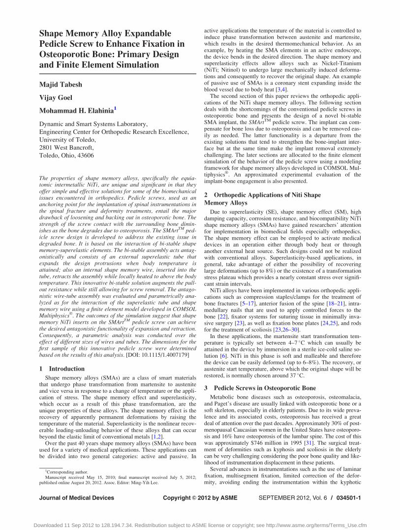
The design consists of bi-stable shape memory-superelastic ele-ments. These elements are mated with a pedicle screw such that itextends itself when implemented in order to augment the screwpurchase as the surrounding bone degrades (see Figs. 2, 3, and 4).The expandable bi-stable insert in the original (Fig. 2(b)) anddeformed (Fig. 2(a)) configurations is shown in Fig. 2. The insertconsists of two parts: a retractor and a protractor. The protractoractivates at body temperature and tends to expand the insert. Theretractor, with austenite transformation temperature (Af) higherthan body temperature, can be activated by heating the assembly.Upon heating above the body temperature, the assembly folds to aform that can be easily unscrewed.
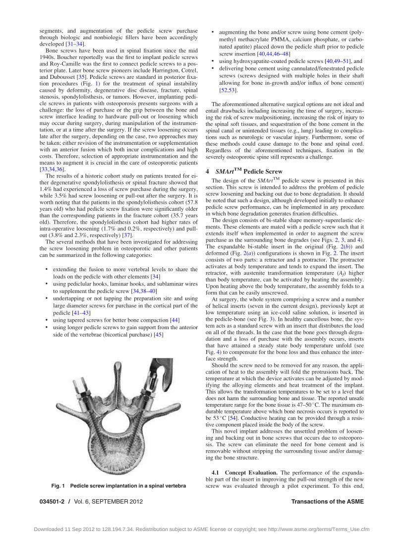
At surgery, the whole system comprising a screw and a numberof helical inserts (seven in the current design), previously kept atlow temperature using an ice-cold saline solution, is inserted inthe pedicle-bone (see Fig. 3). In healthy cancellous bone, the sys-tem acts as a standard screw with an insert that distributes the loadon all of the threads. In the case that the bone goes through degra-dation and a loss of purchase with the assembly occurs, insertsthat have attained a steady state body temperature unfold (seeFig. 4) to compensate for the bone loss and thus enhance the inter-face strength.
Should the screw need to be removed for any reason, the appli-cation of heat to the assembly will fold the protrusions back. Thetemperature at which the device activates can be adjusted by mod-ifying the alloying elements and heat treatment of the implant.This allows the transformation temperatures to be set to a level thatdoes not harm the surrounding bone and tissue. The reported unsafetemperature range for the bone tissue is 47–50 �C. The maximum en-durable temperature above which bone necrosis occurs is reported tobe 53 �C [54]. Conductive heating can be provided through a resis-tive component placed inside the body of the screw.
This novel implant addresses the unsettled problem of loosen-ing and backing out in bone screws that occurs due to osteoporo-sis. The screw can eliminate the need for bone cement and isremovable without stripping the surrounding tissue and/or damag-ing the bone structure.
4.1 Concept Evaluation. The performance of the expanda-ble part of the insert in improving the pull-out strength of the newscrew was evaluated through a pilot experiment. To this end,Fig. 1 Pedicle screw implantation in a spinal vertebra
034501-2 / Vol. 6, SEPTEMBER 2012 Transactions of the ASME
Downloaded 11 Sep 2012 to 128.194.7.34. Redistribution subject to ASME license or copyright; see http://www.asme.org/terms/Terms_Use.cfm
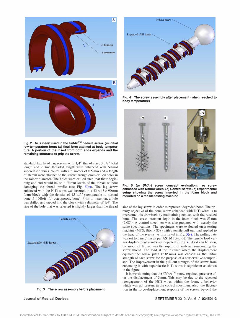
standard hex head lag screws with 1/400 thread size, 3 1/200 totallength and 2 3/400 threaded length were enhanced with Nitinolsuperelastic wires. Wires with a diameter of 0.5 mm and a lengthof 16 mm were attached to the screw through cross drilled holes inthe minor diameter. The holes were drilled such that their begin-ning and end would be on different levels of the thread withoutdamaging the thread profile (see Fig. 5(a)). The lag screwenhanced with the NiTi wires was inserted in a 43� 43� 90 mmfoam block with the density of 15 lb/ft3 (comparable to normalbone; 5–10 lb/ft3 for osteoporotic bone). Prior to insertion, a holewas drilled and tapped into the block with a diameter of 1/400. Thesize of the hole that was selected is slightly larger than the thread size of the lag screw in order to represent degraded bone. The pri-
mary objective of the bone screw enhanced with NiTi wires is toovercome this drawback by maintaining contact with the recededbone. The screw insertion depth in the foam block was 53 mm(2.0800). A control specimen was also prepared with exactly thesame specifications. The specimens were evaluated on a testingmachine (MTS, Bionix 858) with a tensile pull-out load applied tothe head of the screws; as illustrated in Fig. 5(c). The pulling ratewas set to 5 mm/min as per ASTM F543-02. The tensile load ver-sus displacement results are depicted in Fig. 6. As it can be seen,the mode of failure was the rupture of material surrounding thescrew thread. The load at the instance where the displacementequaled the screw pitch (2.85 mm) was chosen as the initialstrength of each screw for the purpose of a conservative compari-son. The improvement in the pull-out strength of the screw fromenhancing it with superelastic NiTi wires is significant as shownin the figure.
It is worth noting that the SMArtTM screw regained purchase af-ter the displacement of 3 mm. This may be due to the repeatedreengagement of the NiTi wires within the foam; a behaviorwhich was not present in the control specimen. Also, the fluctua-tion in the force-displacement response of the screws beyond theFig. 3 The screw assembly before placement
Fig. 4 The screw assembly after placement (when reached tobody temperature)
Fig. 5 (a) SMArt screw concept evaluation: lag screwenhanced with Nitinol wires. (b) Control screw. (c) Experimentalsetup showing the screw inserted in the foam block andmounted on a tensile testing machine.
Fig. 2 NiTi insert used in the SMArtTM pedicle screw. (a) Initiallow-temperature form; (b) final form attained at body tempera-ture. A portion of the insert from both ends expands and theremaining contracts to grip the screw.
Journal of Medical Devices SEPTEMBER 2012, Vol. 6 / 034501-3
Downloaded 11 Sep 2012 to 128.194.7.34. Redistribution subject to ASME license or copyright; see http://www.asme.org/terms/Terms_Use.cfm

initial strength level is likely due to the rupturing nature of thepull-out test. This experiment demonstrated the effectiveness andmerit of the proposed concept.
5 Finite Element Analysis of the SMArtTM
Pedicle Screw
The functionality of the screw in engaging with and disengag-ing from the bone is evaluated through a bi-stable NiTi tube-wireassembly. In this assembly, as shown in Figs. 7(a)–7(d), the tube
is superelastic at body temperature. The tube is shape set toengage the assembly with the surrounding bone in response to ex-posure to body heat. A NiTi wire is inserted inside the tube. Thewire is shape set to disengage the assembly from the surroundingbone when heated to above body temperature. Figure 7 shows theopposing curves in the plane in which the tube and wire deflectwhen activated. The tube and wire can be viewed as two seriallyconnected springs with nonlinear stiffness properties. This analy-sis includes the following assumptions. The shear force betweenthe wire and the tube is neglected, assuming the same curvature atevery cross section.
Figure 7 also represents the functionality of the wire-tube as-sembly. dA1 and dB1 are the required opposing deformations ofthe wire and the tube from the straight form in the shape settingprocess. According to Fig. 7, the overall deflection of the assem-bly at body temperature, DL, can be solved via the following equi-librium equations:
FA2 � FB2 ¼ 0
dA2 þ dB2 � dB1 � dA1 ¼ 0
�(1)
DL ¼ dB1 � dB2 ¼ dA2 � dA1 (2)
By the same token, the overall deflection of the assembly at hightemperature, DH, can be found by:
FA3 � FB3 ¼ 0
dA3 þ dB3 � dB1 � dA1 ¼ 0
�(3)
DH ¼ dB1 � dB3 ¼ dA3 � dA1 (4)
In these equations, the subscript 1 represents the shape set form,subscript 2 represents the body temperature shape, and subscript 3corresponds to the elevated temperature form.
As Eqs. (1)–(4) and Fig. 7 indicate, the design parameters DL
and DH define the functionality of the assembly. DL correspondsto the amount of engagement of the NiTi assembly with the sur-rounding bone while at body temperature. DH characterizes the re-traction of the assembly at elevated temperature. In order toproduce the desired functionality of expansion and retraction forthe SMArtTM pedicle screw, a wire and a tube with proper geome-tries should be shape set to the appropriate shape. In order to findthese geometric properties, a finite element model developed in
Fig. 6 Results of the axial tensile test: force versus displace-ment. The tensile strength is selected to be the force requiredto displace the screw in the block as much as the screw threadpitch.
Fig. 7 Schematic procedure representing the functionality of the antagonistic bi-stable tube-wire assembly in engaging with and disengaging from the bone. (a) and (b) Initial memorizedshapes of the assembly components attained by proper shape setting. Assembly at (c) bodytemperature (d) elevated temperature.
034501-4 / Vol. 6, SEPTEMBER 2012 Transactions of the ASME
Downloaded 11 Sep 2012 to 128.194.7.34. Redistribution subject to ASME license or copyright; see http://www.asme.org/terms/Terms_Use.cfm
COMSOL MultiphysicsVR
incorporating the shape memory behav-ior is used as explained in Sec. 5.1.
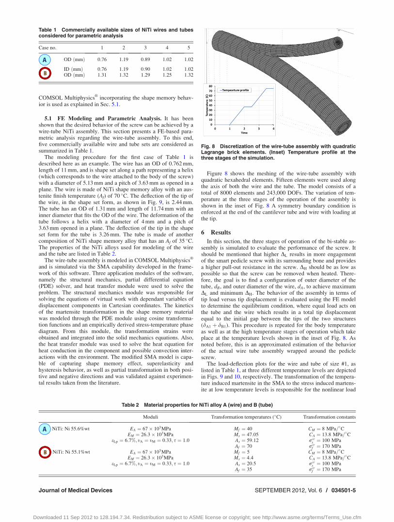
5.1 FE Modeling and Parametric Analysis. It has beenshown that the desired behavior of the screw can be achieved by awire-tube NiTi assembly. This section presents a FE-based para-metric analysis regarding the wire-tube assembly. To this end,five commercially available wire and tube sets are considered assummarized in Table 1.
The modeling procedure for the first case of Table 1 isdescribed here as an example. The wire has an OD of 0.762 mm,length of 11 mm, and is shape set along a path representing a helix(which corresponds to the wire attached to the body of the screw)with a diameter of 5.13 mm and a pitch of 3.63 mm as opened in aplane. The wire is made of NiTi shape memory alloy with an aus-tenite finish temperature (Af) of 70 �C. The deflection of the tip ofthe wire, in the shape set form, as shown in Fig. 9, is 2.44 mm.The tube has an OD of 1.31 mm and length of 11.74 mm with aninner diameter that fits the OD of the wire. The deformation of thetube follows a helix with a diameter of 4 mm and a pitch of3.63 mm opened in a plane. The deflection of the tip in the shapeset form for the tube is 3.26 mm. The tube is made of anothercomposition of NiTi shape memory alloy that has an Af of 35 �C.The properties of the NiTi alloys used for modeling of the wireand the tube are listed in Table 2.
The wire-tube assembly is modeled in COMSOL MultiphysicsVR
and is simulated via the SMA capability developed in the frame-work of this software. Three application modules of the software,namely the structural mechanics, partial differential equation(PDE) solver, and heat transfer module were used to solve theproblem. The structural mechanics module was responsible forsolving the equations of virtual work with dependant variables ofdisplacement components in Cartesian coordinates. The kineticsof the martensite transformation in the shape memory materialwas modeled through the PDE module using cosine transforma-tion functions and an empirically derived stress-temperature phasediagram. From this module, the transformation strains wereobtained and integrated into the solid mechanics equations. Also,the heat transfer module was used to solve the heat equation forheat conduction in the component and possible convection inter-actions with the environment. The modified SMA model is capa-ble of capturing shape memory effect, superelasticity andhysteresis behavior, as well as partial transformation in both posi-tive and negative directions and was validated against experimen-tal results taken from the literature.
Figure 8 shows the meshing of the wire-tube assembly withquadratic hexahedral elements. Fifteen elements were used alongthe axis of both the wire and the tube. The model consists of atotal of 8000 elements and 243,000 DOFs. The variation of tem-perature at the three stages of the operation of the assembly isshown in the inset of Fig. 8 A symmetry boundary condition isenforced at the end of the cantilever tube and wire with loading atthe tip.
6 Results
In this section, the three stages of operation of the bi-stable as-sembly is simulated to evaluate the performance of the screw. Itshould be mentioned that higher DL results in more engagementof the smart pedicle screw with its surrounding bone and providesa higher pull-out resistance in the screw. DH should be as low aspossible so that the screw can be removed when heated. There-fore, the goal is to find a configuration of outer diameter of thetube, dB, and outer diameter of the wire, dA, to achieve maximumDL and minimum DH. The behavior of the assembly in terms oftip load versus tip displacement is evaluated using the FE modelto determine the equilibrium condition, where equal load acts onthe tube and the wire which results in a total tip displacementequal to the initial gap between the tips of the two structures(dA1 þ dB1). This procedure is repeated for the body temperatureas well as at the high temperature stages of operation which takeplace at the temperature levels shown in the inset of Fig. 8. Asnoted before, this is an approximated estimation of the behaviorof the actual wire tube assembly wrapped around the pediclescrew.
The load-deflection plots for the wire and tube of size #1, aslisted in Table 1, at three different temperature levels are depictedin Figs. 9 and 10, respectively. The transformation of the tempera-ture induced martensite in the SMA to the stress induced martens-ite at low temperature levels is responsible for the nonlinear load
Table 1 Commercially available sizes of NiTi wires and tubesconsidered for parametric analysis
Case no. 1 2 3 4 5
OD ðmmÞ 0:76 1:19 0:89 1:02 1:02
ID ðmmÞ 0:76 1:19 0:90 1:02 1:02OD ðmmÞ 1:31 1:32 1:29 1:25 1:32
Table 2 Material properties for NiTi alloy A (wire) and B (tube)
Moduli Transformation temperatures (�C) Transformation constants
NiTi: Ni 55.6%wt EA ¼ 67� 103MPa Mf ¼ 40 CM ¼ 8 MPa=�CEM ¼ 26:3� 103MPa Ms ¼ 47:05 CA ¼ 13:8 MPa=�C
eLp ¼ 6:7%; tA ¼ tM ¼ 0:33; s ¼ 1:0 As ¼ 59:12 rcrs ¼ 100 MPa
Af ¼ 70 rcrf ¼ 170 MPa
NiTi: Ni 55.1%wt EA ¼ 67� 103MPa Mf ¼ 5 CM ¼ 8 MPa=�CEM ¼ 26:3� 103MPa Ms ¼ 4:4 CA ¼ 13:8 MPa=�C
eLp ¼ 6:7%; tA ¼ tM ¼ 0:33; s ¼ 1:0 As ¼ 20:5 rcrs ¼ 100 MPa
Af ¼ 35 rcrf ¼ 170 MPa
Fig. 8 Discretization of the wire-tube assembly with quadraticLagrange brick elements. (Inset) Temperature profile at thethree stages of the simulation.
Journal of Medical Devices SEPTEMBER 2012, Vol. 6 / 034501-5
Downloaded 11 Sep 2012 to 128.194.7.34. Redistribution subject to ASME license or copyright; see http://www.asme.org/terms/Terms_Use.cfm
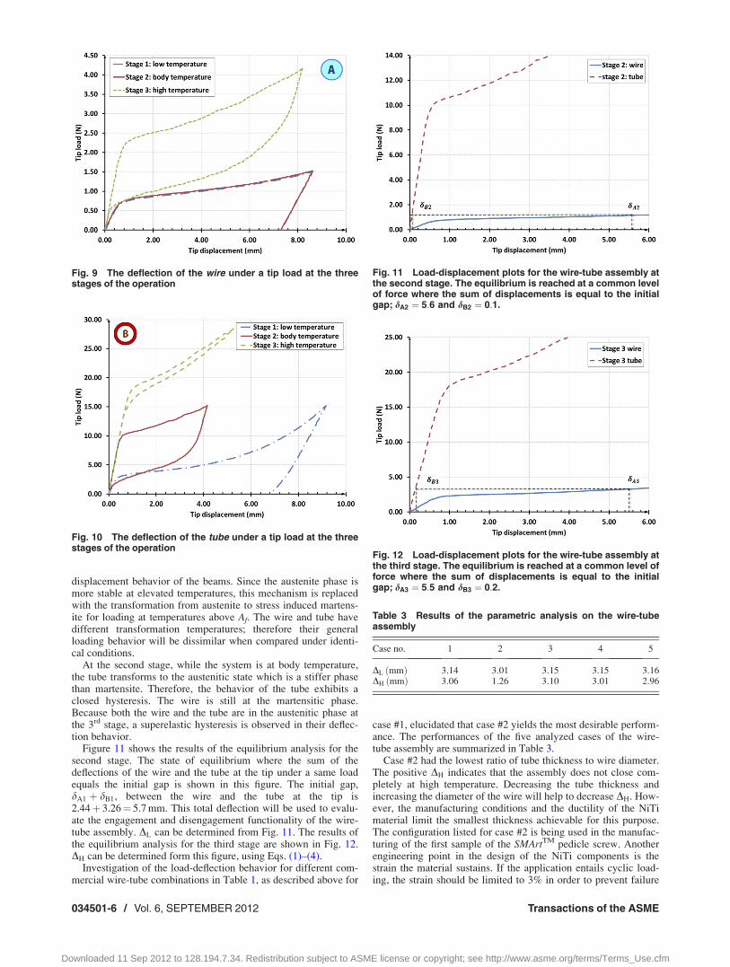
displacement behavior of the beams. Since the austenite phase ismore stable at elevated temperatures, this mechanism is replacedwith the transformation from austenite to stress induced martens-ite for loading at temperatures above Af. The wire and tube havedifferent transformation temperatures; therefore their generalloading behavior will be dissimilar when compared under identi-cal conditions.
At the second stage, while the system is at body temperature,the tube transforms to the austenitic state which is a stiffer phasethan martensite. Therefore, the behavior of the tube exhibits aclosed hysteresis. The wire is still at the martensitic phase.Because both the wire and the tube are in the austenitic phase atthe 3rd stage, a superelastic hysteresis is observed in their deflec-tion behavior.
Figure 11 shows the results of the equilibrium analysis for thesecond stage. The state of equilibrium where the sum of thedeflections of the wire and the tube at the tip under a same loadequals the initial gap is shown in this figure. The initial gap,dA1 þ dB1, between the wire and the tube at the tip is2.44þ 3.26¼ 5.7 mm. This total deflection will be used to evalu-ate the engagement and disengagement functionality of the wire-tube assembly. DL can be determined from Fig. 11. The results ofthe equilibrium analysis for the third stage are shown in Fig. 12.DH can be determined form this figure, using Eqs. (1)–(4).
Investigation of the load-deflection behavior for different com-mercial wire-tube combinations in Table 1, as described above for
case #1, elucidated that case #2 yields the most desirable perform-ance. The performances of the five analyzed cases of the wire-tube assembly are summarized in Table 3.
Case #2 had the lowest ratio of tube thickness to wire diameter.The positive DH indicates that the assembly does not close com-pletely at high temperature. Decreasing the tube thickness andincreasing the diameter of the wire will help to decrease DH. How-ever, the manufacturing conditions and the ductility of the NiTimaterial limit the smallest thickness achievable for this purpose.The configuration listed for case #2 is being used in the manufac-turing of the first sample of the SMArtTM pedicle screw. Anotherengineering point in the design of the NiTi components is thestrain the material sustains. If the application entails cyclic load-ing, the strain should be limited to 3% in order to prevent failure
Fig. 10 The deflection of the tube under a tip load at the threestages of the operation
Fig. 11 Load-displacement plots for the wire-tube assembly atthe second stage. The equilibrium is reached at a common levelof force where the sum of displacements is equal to the initialgap; dA2 ¼ 5:6 and dB2 ¼ 0:1.
Fig. 12 Load-displacement plots for the wire-tube assembly atthe third stage. The equilibrium is reached at a common level offorce where the sum of displacements is equal to the initialgap; dA3 ¼ 5:5 and dB3 ¼ 0:2.
Table 3 Results of the parametric analysis on the wire-tubeassembly
Case no. 1 2 3 4 5
DL ðmmÞ 3:14 3:01 3:15 3:15 3:16DH ðmmÞ 3:06 1:26 3:10 3:01 2:96
Fig. 9 The deflection of the wire under a tip load at the threestages of the operation
034501-6 / Vol. 6, SEPTEMBER 2012 Transactions of the ASME
Downloaded 11 Sep 2012 to 128.194.7.34. Redistribution subject to ASME license or copyright; see http://www.asme.org/terms/Terms_Use.cfm
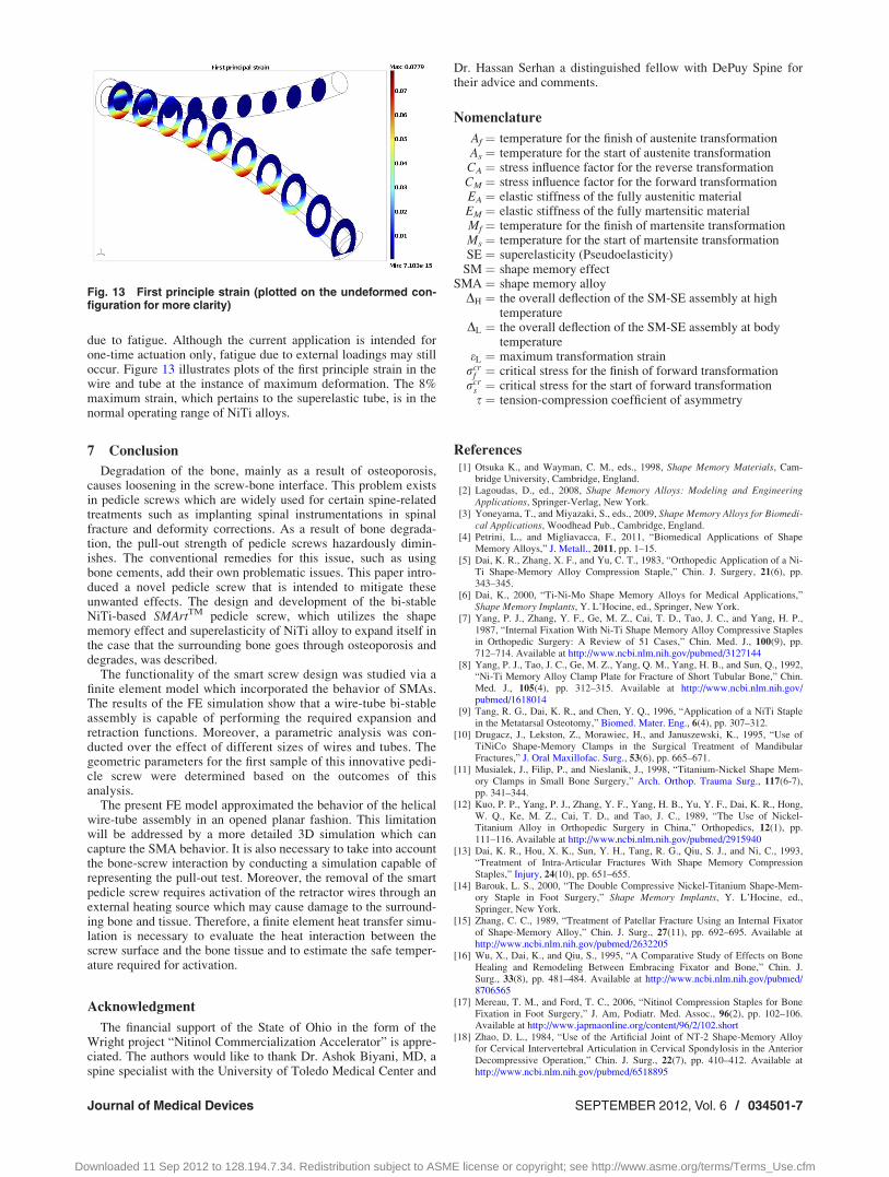
due to fatigue. Although the current application is intended forone-time actuation only, fatigue due to external loadings may stilloccur. Figure 13 illustrates plots of the first principle strain in thewire and tube at the instance of maximum deformation. The 8%maximum strain, which pertains to the superelastic tube, is in thenormal operating range of NiTi alloys.
7 Conclusion
Degradation of the bone, mainly as a result of osteoporosis,causes loosening in the screw-bone interface. This problem existsin pedicle screws which are widely used for certain spine-relatedtreatments such as implanting spinal instrumentations in spinalfracture and deformity corrections. As a result of bone degrada-tion, the pull-out strength of pedicle screws hazardously dimin-ishes. The conventional remedies for this issue, such as usingbone cements, add their own problematic issues. This paper intro-duced a novel pedicle screw that is intended to mitigate theseunwanted effects. The design and development of the bi-stableNiTi-based SMArtTM pedicle screw, which utilizes the shapememory effect and superelasticity of NiTi alloy to expand itself inthe case that the surrounding bone goes through osteoporosis anddegrades, was described.
The functionality of the smart screw design was studied via afinite element model which incorporated the behavior of SMAs.The results of the FE simulation show that a wire-tube bi-stableassembly is capable of performing the required expansion andretraction functions. Moreover, a parametric analysis was con-ducted over the effect of different sizes of wires and tubes. Thegeometric parameters for the first sample of this innovative pedi-cle screw were determined based on the outcomes of thisanalysis.
The present FE model approximated the behavior of the helicalwire-tube assembly in an opened planar fashion. This limitationwill be addressed by a more detailed 3D simulation which cancapture the SMA behavior. It is also necessary to take into accountthe bone-screw interaction by conducting a simulation capable ofrepresenting the pull-out test. Moreover, the removal of the smartpedicle screw requires activation of the retractor wires through anexternal heating source which may cause damage to the surround-ing bone and tissue. Therefore, a finite element heat transfer simu-lation is necessary to evaluate the heat interaction between thescrew surface and the bone tissue and to estimate the safe temper-ature required for activation.
Acknowledgment
The financial support of the State of Ohio in the form of theWright project “Nitinol Commercialization Accelerator” is appre-ciated. The authors would like to thank Dr. Ashok Biyani, MD, aspine specialist with the University of Toledo Medical Center and
Dr. Hassan Serhan a distinguished fellow with DePuy Spine fortheir advice and comments.
Nomenclature
Af ¼ temperature for the finish of austenite transformationAs ¼ temperature for the start of austenite transformationCA ¼ stress influence factor for the reverse transformationCM ¼ stress influence factor for the forward transformationEA ¼ elastic stiffness of the fully austenitic materialEM ¼ elastic stiffness of the fully martensitic materialMf ¼ temperature for the finish of martensite transformationMs ¼ temperature for the start of martensite transformationSE ¼ superelasticity (Pseudoelasticity)
SM ¼ shape memory effectSMA ¼ shape memory alloy
DH ¼ the overall deflection of the SM-SE assembly at hightemperature
DL ¼ the overall deflection of the SM-SE assembly at bodytemperature
eL ¼ maximum transformation strainrcr
f ¼ critical stress for the finish of forward transformationrcr
s ¼ critical stress for the start of forward transformations ¼ tension-compression coefficient of asymmetry
References[1] Otsuka K., and Wayman, C. M., eds., 1998, Shape Memory Materials, Cam-
bridge University, Cambridge, England.[2] Lagoudas, D., ed., 2008, Shape Memory Alloys: Modeling and Engineering
Applications, Springer-Verlag, New York.[3] Yoneyama, T., and Miyazaki, S., eds., 2009, Shape Memory Alloys for Biomedi-
cal Applications, Woodhead Pub., Cambridge, England.[4] Petrini, L., and Migliavacca, F., 2011, “Biomedical Applications of Shape
Memory Alloys,” J. Metall., 2011, pp. 1–15.[5] Dai, K. R., Zhang, X. F., and Yu, C. T., 1983, “Orthopedic Application of a Ni-
Ti Shape-Memory Alloy Compression Staple,” Chin. J. Surgery, 21(6), pp.343–345.
[6] Dai, K., 2000, “Ti-Ni-Mo Shape Memory Alloys for Medical Applications,”Shape Memory Implants, Y. L’Hocine, ed., Springer, New York.
[7] Yang, P. J., Zhang, Y. F., Ge, M. Z., Cai, T. D., Tao, J. C., and Yang, H. P.,1987, “Internal Fixation With Ni-Ti Shape Memory Alloy Compressive Staplesin Orthopedic Surgery: A Review of 51 Cases,” Chin. Med. J., 100(9), pp.712–714. Available at http://www.ncbi.nlm.nih.gov/pubmed/3127144
[8] Yang, P. J., Tao, J. C., Ge, M. Z., Yang, Q. M., Yang, H. B., and Sun, Q., 1992,“Ni-Ti Memory Alloy Clamp Plate for Fracture of Short Tubular Bone,” Chin.Med. J., 105(4), pp. 312–315. Available at http://www.ncbi.nlm.nih.gov/pubmed/1618014
[9] Tang, R. G., Dai, K. R., and Chen, Y. Q., 1996, “Application of a NiTi Staplein the Metatarsal Osteotomy,” Biomed. Mater. Eng., 6(4), pp. 307–312.
[10] Drugacz, J., Lekston, Z., Morawiec, H., and Januszewski, K., 1995, “Use ofTiNiCo Shape-Memory Clamps in the Surgical Treatment of MandibularFractures,” J. Oral Maxillofac. Surg., 53(6), pp. 665–671.
[11] Musialek, J., Filip, P., and Nieslanik, J., 1998, “Titanium-Nickel Shape Mem-ory Clamps in Small Bone Surgery,” Arch. Orthop. Trauma Surg., 117(6-7),pp. 341–344.
[12] Kuo, P. P., Yang, P. J., Zhang, Y. F., Yang, H. B., Yu, Y. F., Dai, K. R., Hong,W. Q., Ke, M. Z., Cai, T. D., and Tao, J. C., 1989, “The Use of Nickel-Titanium Alloy in Orthopedic Surgery in China,” Orthopedics, 12(1), pp.111–116. Available at http://www.ncbi.nlm.nih.gov/pubmed/2915940
[13] Dai, K. R., Hou, X. K., Sun, Y. H., Tang, R. G., Qiu, S. J., and Ni, C., 1993,“Treatment of Intra-Articular Fractures With Shape Memory CompressionStaples,” Injury, 24(10), pp. 651–655.
[14] Barouk, L. S., 2000, “The Double Compressive Nickel-Titanium Shape-Mem-ory Staple in Foot Surgery,” Shape Memory Implants, Y. L’Hocine, ed.,Springer, New York.
[15] Zhang, C. C., 1989, “Treatment of Patellar Fracture Using an Internal Fixatorof Shape-Memory Alloy,” Chin. J. Surg., 27(11), pp. 692–695. Available athttp://www.ncbi.nlm.nih.gov/pubmed/2632205
[16] Wu, X., Dai, K., and Qiu, S., 1995, “A Comparative Study of Effects on BoneHealing and Remodeling Between Embracing Fixator and Bone,” Chin. J.Surg., 33(8), pp. 481–484. Available at http://www.ncbi.nlm.nih.gov/pubmed/8706565
[17] Mereau, T. M., and Ford, T. C., 2006, “Nitinol Compression Staples for BoneFixation in Foot Surgery,” J. Am, Podiatr. Med. Assoc., 96(2), pp. 102–106.Available at http://www.japmaonline.org/content/96/2/102.short
[18] Zhao, D. L., 1984, “Use of the Artificial Joint of NT-2 Shape-Memory Alloyfor Cervical Intervertebral Articulation in Cervical Spondylosis in the AnteriorDecompressive Operation,” Chin. J. Surg., 22(7), pp. 410–412. Available athttp://www.ncbi.nlm.nih.gov/pubmed/6518895
Fig. 13 First principle strain (plotted on the undeformed con-figuration for more clarity)
Journal of Medical Devices SEPTEMBER 2012, Vol. 6 / 034501-7
Downloaded 11 Sep 2012 to 128.194.7.34. Redistribution subject to ASME license or copyright; see http://www.asme.org/terms/Terms_Use.cfm
[19] Ricart, O., 2000, “The Use of a Memory-Shape Staple in Cervical AnteriorFusion (About 100 Human Implantations),” Shape Memory Implants, Y.L’Hocine, ed., Springer, New York.
[20] Kim, Y., and Zhang, H., 2006, “Shape Memory Implant (KIMPF-DI Fixing)System,” Dynamic Reconstruction of the Spine, D. Kim, F. Cammisa, and R.Fessler, eds., Thieme Medical Publishers Inc., New York.
[21] Silberstein, B. M., and Gunter, V., 2000, “Shape Memory Implants in SpinalSurgery: Long-Term Results (Experimental and Clinical Studies),” Shape Mem-ory Implants, Y. L’Hocine, ed., Springer, New York.
[22] Kujala, S., Ryhanen, J., Jamsa, T., Danilov, A., Saaranen, J., Pramila, A., andTuukkanen, J., 2002, “Bone Modeling Controlled by a Nickel-Titanium ShapeMemory Alloy Intramedullary Nail,” Biomaterials, 23, pp. 2535–2543.
[23] Xu, W., Frank, T. G., Stockham, G., and Cuschieri, A, 1999, “Shape MemoryAlloy Fixator System for Suturing Tissue in Minimal Access Surgery,” AnnalsBiomed. Eng., 27(5), pp. 663–669.
[24] Tomitsuka, K., 1991, “Study of Mechanical Properties of Shape Memory AlloyPlate for Internal Fixation of Jaws,” J. Stomatol. Soc., 58(1), pp. 59–73.
[25] Dai, K. R., Ni, C., and Wu, X. T., 1994, “An Experimental Study and Prelimi-nary Clinical Report of Shape-Memory Saw Tooth-Arm Embracing InternalFixator,” Chin. J. Surg., 32(10), pp. 629–632. Available at http://www.ncbi.nlm.nih.gov/pubmed/7750426
[26] Sanders, J. O., Sanders, A. E., More, R., and Ashman, R. B., 1993, “A Prelimi-nary Investigation of Shape Memory Alloys in the Surgical Correction ofScoliosis,” Spine, 18(12), pp. 1640–1646.
[27] Veldhuizen, A. G., Sanders, M. M., and Cool, J. C., 1997, “A ScoliosisCorrection Device Based on Memory Metal,” Med. Eng. Phys., 19(2), pp.171–179.
[28] Wever, D. J., Elstrodt, J. A., Veldhuizen, A. G., and Horn, J. R., 2002,“Scoliosis Correction With Shape-Memory Metal: Results of an ExperimentalStudy,” Eur. Spine J., 11, pp. 100–106.
[29] Schmerling, M. A., Wilkov, M. A., Sanders, A. E., and Woosley, J. E., 1976,“Using the Shape Recovery of Nitinol in the Harrington Rod Treatment ofScoliosis,” J. Biomed. Mater. Res., 10(6), pp. 879–892.
[30] Jinfang, G., Ping, I., Jifang, W., and Li, S., 1990, “Scoliosis Correction Rods ofTi-Ni Alloy and Clinical Application,” Proceedings of the International Sympo-sium of Shape Memory Alloys, Guilin, China, 1986, China Academic Pub-lisher, Beijing, China.
[31] Melton, L. J., 1997, “Epidemiology of Spinal Osteoporosis,” Spine, 22(24S),Supp. 2S–11S.
[32] Glassman, S. D., and Alegre, G. M., 2003, “Adult Spinal Deformity in theOsteoporotic Spine: Options and Pitfalls,” Instr. Course Lect., 52, pp. 579–588.Available at http://www.ncbi.nlm.nih.gov/pubmed/12690884
[33] Shigeru, S., Shiba, R., Kondo, H., and Murota, K., 1991, “An ExperimentalStudy on Transpedicular Screw Fixation in Relation to Osteoporosis of theLumbar Spine,” Spine, 16(11), pp. 1335–1341.
[34] Hu, S. S., 1997, “Internal Fixation in the Osteoporotic Spine,” Spine, 22(24S),Supp. 43S–48S.
[35] Gaines, R. W., 2000, “The Use of Pedicle-Screw Internal Fixation for the Oper-ative Treatment of Spinal Disorder,” J. Bone Jt. Surg., Am., 82, pp. 1458–1476.
[36] Inceoglu, S., 2004, “Failure of Pedicle Screw-Bone Interface: Biomechanics ofPedicle Screw Insertion and Pullout,” Ph.D. thesis, Cleveland State University,Cleveland, OH.
[37] Yuan, H. A., Garfin S. R., Dickman, C. A., and Mardjetko, S. M., 1994, “A His-torical Cohort Study of Pedicle Screw Fixation in Thoracic, Lumbar, and SacralSpine Fusion,” Spine, 19(20S), Supp. pp. 2279S–2296S.
[38] Hasegawa, K., Takahashi, H. E., Takahashi, H. E., Uchiyama, S., Hirano, T.,Hara, T., Washio, T., Sugiura, T., Youkaichiya, M., and Ikeda, M., 1997, “AnExperimental Study of a Combination Method Using a Pedicle Screw and Lam-inar Hook for the Osteoporotic Spine,” Spine, 22(9), pp. 958–962.
[39] Chiba, M., McLain, R. F., Yerby, S. A., Moseley, T. A., Smith, T. S., and Ben-son, D. R., 1996, “Short-Segment Pedicle Instrumentation: BiomechanicalAnalysis of Supplemental Hook Fixation,” Spine, 21, pp. 288–294.
[40] Sarzier, J. S., Evans, A. J., and Cahill, D. W., 2002, “Increased Pedicle ScrewPullout Strength With Vertebroplasty Augmentation in Osteoporotic Spine,” J.Neurosurg., 96, pp. 309–312.
[41] Zdeblick, T. A., Kunaz, D. N., Cook, M. E., and McCabe, R., 1993, “PedicleScrew Pull-Out Strength: Correlation With Insertional Torque,” Spine, 18, pp.1673–1676.
[42] Battula, S., Schoenfeld, A. J., Sahai, V., Vrabec, G. A., Tank, J., and Njus, G. O.,2008, “The Effect of Pilot Hole Size on the Insertion Torque and Pullout Strengthof Self-Tapping Cortical Bone Screws in Osteoporotic Bone,” J. Trauma; Inj.Infect., Crit. Care, 64(4), pp. 990–995.
[43] Daftari, T. K., Horton, W. C., and Hutton, W.C., 1994, “Correlations BetweenScrew Hole Preparation, Torque of Insertion, and Pullout Strength for SpinalScrews,” J. Spinal Disord., 7, pp. 139–145.
[44] Abshire, B. B., McLain, R. F., Valdevit, A., and Kambic, H. E., 2001,“Characteristics of Pullout Failure in Conical and Cylindrical Pedicle ScrewsAfter Full Insertion and Back-Out,” Spine J., 1, 408–414.
[45] Zindrick, M. R., Wiltse, L. L., Widell, E. H., Thomas, J. C., Holland, W. R.,Field, F. T., and Spencer, C. W., 1986, “A Biomechanical Study of Intrapedicu-lar Screw Fixation in the Lumbosacral Spine,” Clin. Orthop., 203, pp. 99–112.
[46] Lotz, J. C., Hu, S. S., Chiu, D. F. M., Yu, M., Colliou, O., and Poser, R. D.,1997, “Carbonated Apatite Cement Augmentation of Pedicle Screw Fixation inthe Lumbar Spine,” Spine, 22, pp. 2716–2723.
[47] Wuisman, P. I. J. M., Dijk, M. V., Staal, H., and Royen, B. J., 2000,“Augmentation of (Pedicle) Screws With Calcium Apatite Cement in PatientsWith Severe Progressive Osteoporotic Spinal Deformities: An InnovativeTechnique,” Eur. Spine J., 9(6), pp. 528–533.
[48] Moore, D. C., Maitra, R. S., Farjo, L. A., Graziano, G. P., and Goldstein, S. A.,1997, “Restoration of Pedicle Screw Fixation With an In Situ Setting CalciumPhosphate Cement,” Spine, 22, pp. 1696–1705.
[49] Hasegawa, T., Inufusa A., Imai, Y., Mikawa, Y., Lim, T., and An, H., 2005,“Hydroxyapatite-Coating of Pedicle Screws Improves Resistance Against Pull-Out Force in the Osteoporotic Canine Lumbar Spine Model: A Pilot Study,”Spine J., 5, pp. 239–243.
[50] Sanden, B., Olerud, C., Johansson, C., and Larsson, S., 2000, “ImprovedExtraction Torque of Hydroxyapatite-Coated Pedicle Screws,” Eur. Spine J., 9,pp. 534–537.
[51] Sanden, B., Olerud, C., and Larsson, S., 2001, “Hydroxyapatite Coating Enhan-ces Fixation of Loaded Pedicle Screws: A Mechanical In Vivo Study in Sheep,”Eur. Spine J., 10, pp. 334–339.
[52] Cook, S. D., Salkeld, S. L., Stanley, T., Faciane, A., and Miler, S. D., 2004,“Biomechanical Study of Pedicle Screw Fixation in Severely OsteoporoticBone,” Spine J., 4, pp. 402–408.
[53] Waits, C., Burton, D., McIff, T., Asher, M., and Glattes, R., 2007, “Cement-Augmentation of Pedicle Screw Fixation Using Novel Cannulated CementInsertion Device,” Spine J., 7(5), Supp. 1, pp. 25S–26S
[54] Eriksson, A. R., and Albrektsson, T., 1983, “Temperature Threshold Levels forHeat-Induced Bone Tissue Injury: A Vital-Microscopic Study in the Rabbit,” J.Prosthet. Dent., 50(1), pp. 101–107.
034501-8 / Vol. 6, SEPTEMBER 2012 Transactions of the ASME
Downloaded 11 Sep 2012 to 128.194.7.34. Redistribution subject to ASME license or copyright; see http://www.asme.org/terms/Terms_Use.cfm