Embed Size (px)
Citation preview
Paper Number O43
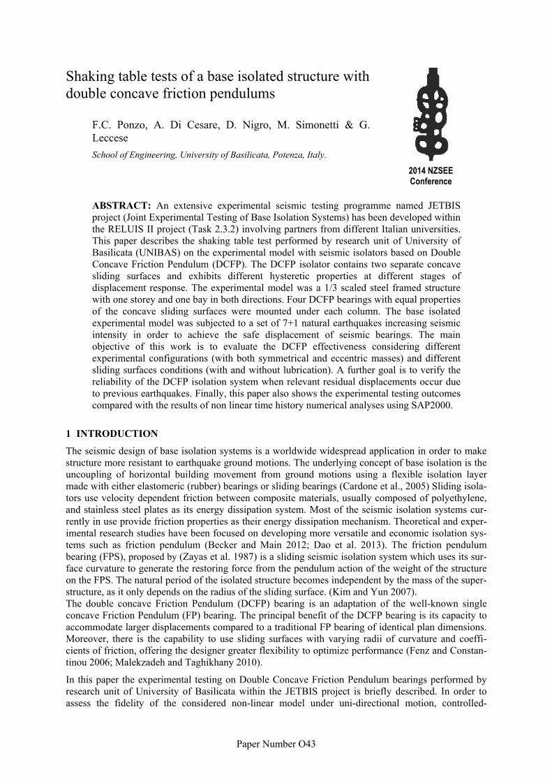
Shaking table tests of a base isolated structure with double concave friction pendulums
2014 NZSEE Conference
F.C. Ponzo, A. Di Cesare, D. Nigro, M. Simonetti & G. Leccese
School of Engineering, University of Basilicata, Potenza, Italy.
ABSTRACT: An extensive experimental seismic testing programme named JETBIS project (Joint Experimental Testing of Base Isolation Systems) has been developed within the RELUIS II project (Task 2.3.2) involving partners from different Italian universities. This paper describes the shaking table test performed by research unit of University of Basilicata (UNIBAS) on the experimental model with seismic isolators based on Double Concave Friction Pendulum (DCFP). The DCFP isolator contains two separate concave sliding surfaces and exhibits different hysteretic properties at different stages of displacement response. The experimental model was a 1/3 scaled steel framed structure with one storey and one bay in both directions. Four DCFP bearings with equal properties of the concave sliding surfaces were mounted under each column. The base isolated experimental model was subjected to a set of 7+1 natural earthquakes increasing seismic intensity in order to achieve the safe displacement of seismic bearings. The main objective of this work is to evaluate the DCFP effectiveness considering different experimental configurations (with both symmetrical and eccentric masses) and different sliding surfaces conditions (with and without lubrication). A further goal is to verify the reliability of the DCFP isolation system when relevant residual displacements occur due to previous earthquakes. Finally, this paper also shows the experimental testing outcomes compared with the results of non linear time history numerical analyses using SAP2000.
1 INTRODUCTION
The seismic design of base isolation systems is a worldwide widespread application in order to make structure more resistant to earthquake ground motions. The underlying concept of base isolation is the uncoupling of horizontal building movement from ground motions using a flexible isolation layer made with either elastomeric (rubber) bearings or sliding bearings (Cardone et al., 2005) Sliding isola-tors use velocity dependent friction between composite materials, usually composed of polyethylene, and stainless steel plates as its energy dissipation system. Most of the seismic isolation systems cur-rently in use provide friction properties as their energy dissipation mechanism. Theoretical and exper-imental research studies have been focused on developing more versatile and economic isolation sys-tems such as friction pendulum (Becker and Main 2012; Dao et al. 2013). The friction pendulum bearing (FPS), proposed by (Zayas et al. 1987) is a sliding seismic isolation system which uses its sur-face curvature to generate the restoring force from the pendulum action of the weight of the structure on the FPS. The natural period of the isolated structure becomes independent by the mass of the super-structure, as it only depends on the radius of the sliding surface. (Kim and Yun 2007). The double concave Friction Pendulum (DCFP) bearing is an adaptation of the well-known single concave Friction Pendulum (FP) bearing. The principal benefit of the DCFP bearing is its capacity to accommodate larger displacements compared to a traditional FP bearing of identical plan dimensions. Moreover, there is the capability to use sliding surfaces with varying radii of curvature and coeffi-cients of friction, offering the designer greater flexibility to optimize performance (Fenz and Constan-tinou 2006; Malekzadeh and Taghikhany 2010).
In this paper the experimental testing on Double Concave Friction Pendulum bearings performed by research unit of University of Basilicata within the JETBIS project is briefly described. In order to assess the fidelity of the considered non-linear model under uni-directional motion, controlled-
2
displacement and seismic-input experiments were performed using shaking table at UNIBAS and at University of Naples “Federico II” (UNINA), respectively. The DCFP isolators have been produced by FIP Industriale containing two separate concave sliding surfaces with same radius of curvature and a rigid slider covered by composite material. The experimental model for seismic tests was a 1/3 scaled steel framed structure with one storey and one bay in both directions considering symmetric and eccentric mass configurations. Four DCFP bearings with equal properties were mounted under each column considering two conditions of the sliding surfaces (with and without lubrication). This paper briefly describes the test set-up and testing results of various experimental model configurations. Comparisons between experimental outcomes and non-linear time history results using finite element programme SAP2000 are also shown.
2 EXPERIMENTAL AND NUMERICAL INVESTIGATIONS
2.1 Experimental model
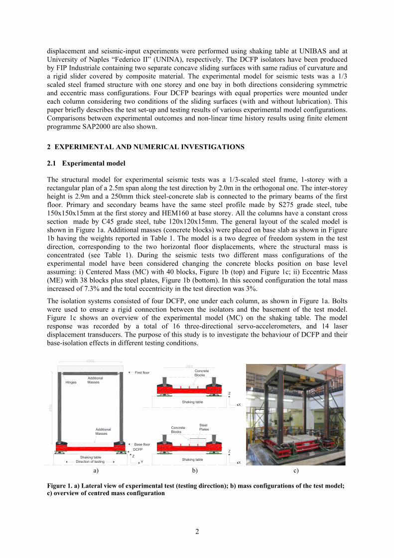
The structural model for experimental seismic tests was a 1/3-scaled steel frame, 1-storey with a rectangular plan of a 2.5m span along the test direction by 2.0m in the orthogonal one. The inter-storey height is 2.9m and a 250mm thick steel-concrete slab is connected to the primary beams of the first floor. Primary and secondary beams have the same steel profile made by S275 grade steel, tube 150x150x15mm at the first storey and HEM160 at base storey. All the columns have a constant cross section made by C45 grade steel, tube 120x120x15mm. The general layout of the scaled model is shown in Figure 1a. Additional masses (concrete blocks) were placed on base slab as shown in Figure 1b having the weights reported in Table 1. The model is a two degree of freedom system in the test direction, corresponding to the two horizontal floor displacements, where the structural mass is concentrated (see Table 1). During the seismic tests two different mass configurations of the experimental model have been considered changing the concrete blocks position on base level assuming: i) Centered Mass (MC) with 40 blocks, Figure 1b (top) and Figure 1c; ii) Eccentric Mass (ME) with 38 blocks plus steel plates, Figure 1b (bottom). In this second configuration the total mass increased of 7.3% and the total eccentricity in the test direction was 3%.
The isolation systems consisted of four DCFP, one under each column, as shown in Figure 1a. Bolts were used to ensure a rigid connection between the isolators and the basement of the test model. Figure 1c shows an overview of the experimental model (MC) on the shaking table. The model response was recorded by a total of 16 three-directional servo-accelerometers, and 14 laser displacement transducers. The purpose of this study is to investigate the behaviour of DCFP and their base-isolation effects in different testing conditions.
YZ
DCFP
Shaking tableDirection of testing
X
Z
SteelPlates
ConcreteBlocks
ConcreteBlocks
X
Z
Shaking table
Shaking table
AdditionalMasses
AdditionalMasses
Base floor
First floor
Hinges
a) b) c)
Figure 1. a) Lateral view of experimental test (testing direction); b) mass configurations of the test model; c) overview of centred mass configuration
3
Table 1. Masses of experimental model configurations.
Storey Centred Mass (MC)
[t]
Eccentric Mass (ME)
[t]
ME eccentricity
[%]
Base 3.20 3.80 10
1st floor 5.00 5.00 0
Total 8.20 8.80 3
2.2 Seismic isolation System
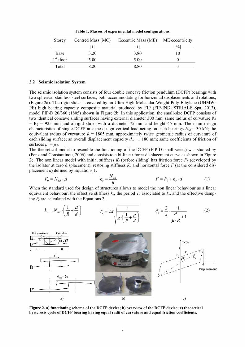
The seismic isolation system consists of four double concave friction pendulum (DCFP) bearings with two spherical stainless steel surfaces, both accommodating for horizontal displacements and rotations, (Figure 2a). The rigid slider is covered by an Ultra-High Molecular Weight Poly-Ethylene (UHMW-PE) high bearing capacity composite material produced by FIP (FIP-INDUSTRIALE Spa, 2013), model FIP-D 20/360 (1805) shown in Figure 2b. In this application, the small-size DCFP consists of two identical concave sliding surfaces having external diameter 300 mm, same radius of curvature R1 = R2 = 925 mm and a rigid slider with a diameter 75 mm and height 45 mm. The main design characteristics of single DCFP are: the design vertical load acting on each bearings Nsd = 30 kN; the equivalent radius of curvature R = 1805 mm, approximately twice geometric radius of curvature of each sliding surface; an overall displacement capacity dmax ± 180 mm; same coefficients of friction of surfaces μ1 = μ 2. The theoretical model to resemble the functioning of the DCFP (FIP-D small series) was studied by (Fenz and Constantinou, 2006) and consists to a bi-linear force-displacement curve as shown in Figure 2c. The non linear model with initial stiffness Ki (before sliding) has friction force F0 (developed by the isolator at zero displacement), restoring stiffness Kr and horizontal force F (at the considered dis-placement d) defined by Equations 1.
μ⋅= SdNF0 R
Nk Sd
r = dkFF r ⋅+= 0 (1)
When the standard used for design of structures allows to model the non linear behaviour as a linear equivalent behaviour, the effective stiffness ke, the period Te associated to ke, and the effective damp-ing ξe are calculated with the Equations 2.
+⋅=
dRNk Sde
μ1
+⋅
=
dRg
Te μπ
11
2
1
12
+⋅
⋅=
Rde
μπ
ξ (2)
a) b) c)
Figure 2. a) functioning scheme of the DCFP device; b) overview of the DCFP device; c) theoretical hysteresis cycle of DCFP bearing having equal radii of curvature and equal friction coefficients.

4
2.3 Numerical Modelling
The steel frame was modelled using frame-type 3D finite elements (Figure 3a) in SAP2000 (SAP2000, 2013). The connection between the columns and the stiff beams at the base of the model was simulat-ed through the use of fixed restraints with the floor slabs being simulated by imposing a rigid dia-phragm assumption. Recently various studies (Kim and Yun, 2007) have been carried out on DCFPs revealed that tri-linear behavior of a DCFP can be achieved by combining two FPS having different friction coefficients. In this work the nonlinear behaviour of the single DCFP isolator has been modelled by using one joint link element type biaxial Friction-Pendulum Isolator, see Figure 3b. The friction and pendulum forces are directly proportional to the compressive axial force in the element which cannot carry axial tension (SAP2000, 2013). The velocity dependence of the coefficient of friction is described by equation 3 (Constantinou et al., 1990), where: v is the sliding velocity; μfast and μslow are the sliding coefficients of friction at maximum and minimum velocity respectively; α is a rate parameter that controls the transi-tion from μslow to μfast .
vfslowfastfast e ⋅−⋅−−= αμμμμ )(
(3)
The numerical simulations have been compared against characterization testing outcomes (see Table 2 shown below) by considering two different non-linear model of DCFP: i) constant friction model whit a rigid-bilinear hysteretic behavior and constant friction, as derived from benchmark test (ki = ki,slow ; μ = μslow ); ii) variable friction model with bilinear hysteretic behavior and velocity dependent friction, as derived from dynamic tests (ki = ki,fast ; μ defined by equation 3).
a) b)
Figure 3. a) Global modelling of the test model; b) Local modelling of a DCFP device (SAP 2000, 2013).
3 EXPERIMENTAL AND NUMERICAL RESULTS
3.1 Characterization Tests
Characterization testing of DCFP bearing has been performed to confirm the theoretical predictions by using the bearing testing machine available at the University of Basilicata. The machine consists of one horizontal actuator and two vertical actuators and is capable of testing bearings under controlled conditions of vertical load, lateral movement and rotational movement. Reaction forces are measured by a load cells mounted directly beneath the actuators and lateral displacement is measured by an internally mounted LVDT on the horizontal actuator.
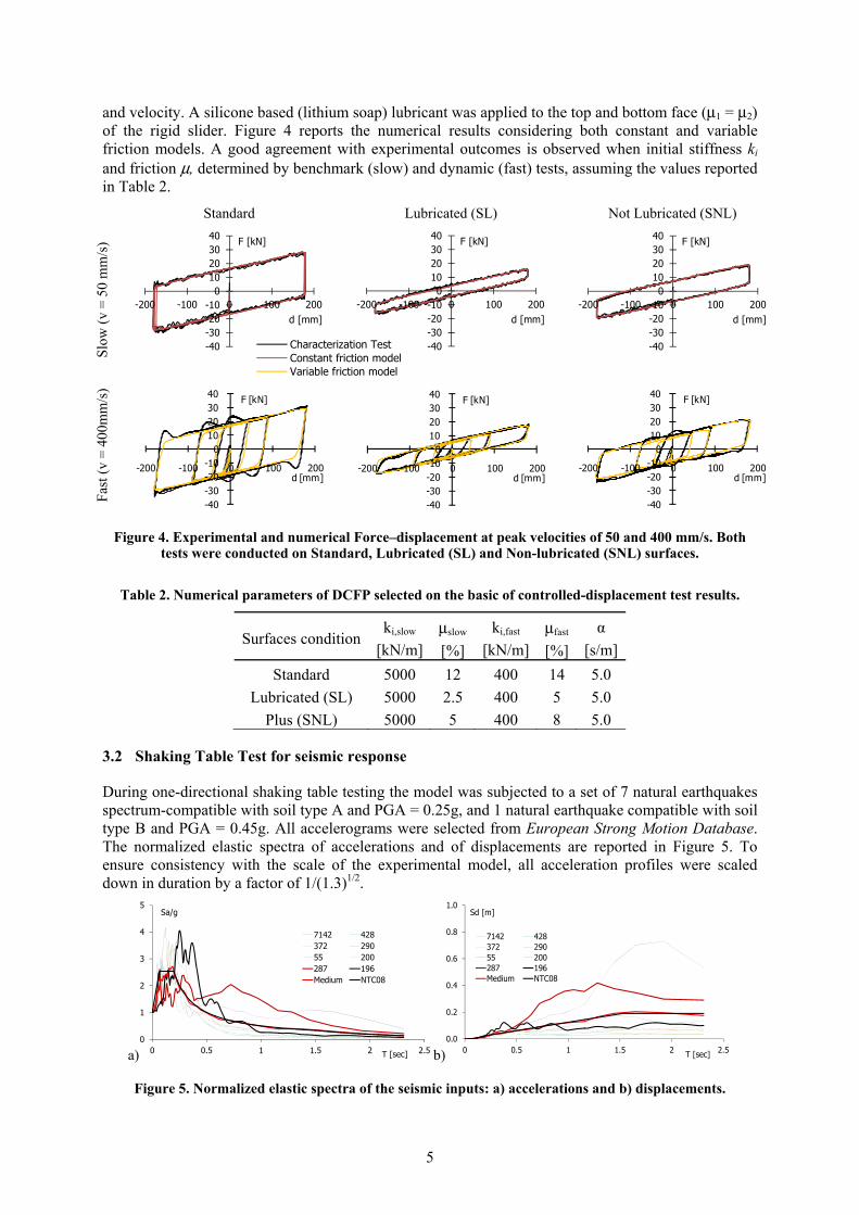
The bearings were tested under a design vertical compressive load N = 32 kN, which represents the minimum value available by test machine. A series of sinusoidal lateral displacement were imposed in accordance with testing of Curved Surface Sliders prescribed by Eurocode (UNI-EN 15129, 2009). Figure 4 shows experimental force-displacement relationships of the DCFP carried out on different conditions of surfaces: i) Standard, ii) Lubricated (SL) and iii) Not-lubricated (SNL). The sliding material is essential to give stability of the hysteretic force vs. displacement curves with displacement
5
and velocity. A silicone based (lithium soap) lubricant was applied to the top and bottom face (μ1 = μ2) of the rigid slider. Figure 4 reports the numerical results considering both constant and variable friction models. A good agreement with experimental outcomes is observed when initial stiffness ki and friction μ, determined by benchmark (slow) and dynamic (fast) tests, assuming the values reported in Table 2.
Standard Lubricated (SL) Not Lubricated (SNL)
Slo
w (
v =
50
mm
/s)
-40-30-20-10
010203040
-200 -100 0 100 200
F [kN]
d [mm]
-40-30-20-10
010203040
-200 -100 0 100 200
F [kN]
d [mm]
-40-30-20-10
010203040
-200 -100 0 100 200
F [kN]
d [mm]
Fas
t (v
= 4
00m
m/s
)
-40-30-20-10
010203040
-200 -100 0 100 200
F [kN]
d [mm]
-40-30-20-10
010203040
-200 -100 0 100 200
F [kN]
d [mm]
-40-30-20-10
010203040
-200 -100 0 100 200
F [kN]
d [mm]
Figure 4. Experimental and numerical Force–displacement at peak velocities of 50 and 400 mm/s. Both tests were conducted on Standard, Lubricated (SL) and Non-lubricated (SNL) surfaces.
Table 2. Numerical parameters of DCFP selected on the basic of controlled-displacement test results.
Surfaces conditionki,slow
[kN/m]
μslow
[%]
ki,fast
[kN/m]
μfast
[%]
α
[s/m]
Standard 5000 12 400 14 5.0
Lubricated (SL) 5000 2.5 400 5 5.0
Plus (SNL) 5000 5 400 8 5.0
3.2 Shaking Table Test for seismic response
During one-directional shaking table testing the model was subjected to a set of 7 natural earthquakes spectrum-compatible with soil type A and PGA = 0.25g, and 1 natural earthquake compatible with soil type B and PGA = 0.45g. All accelerograms were selected from European Strong Motion Database. The normalized elastic spectra of accelerations and of displacements are reported in Figure 5. To ensure consistency with the scale of the experimental model, all acceleration profiles were scaled down in duration by a factor of 1/(1.3)1/2.
a)0
1
2
3
4
5
0 0.5 1 1.5 2 2.5
Sa/g
T [sec]
7142 428372 29055 200287 196Medium NTC08
b)0.0
0.2
0.4
0.6
0.8
1.0
0 0.5 1 1.5 2 2.5
Sd [m]
T [sec]
7142 428372 29055 200287 196Medium NTC08
Figure 5. Normalized elastic spectra of the seismic inputs: a) accelerations and b) displacements.
Characterization TestConstant friction modelVariable friction model

6
Three experimental configurations have been considered for a total of 64 seismic tests (Table 3): i) configuration MC-SNL with centred mass (bearing axial load NEd = 20.5 kN) and not-lubricated surfaces (μslow = 5%; μfast = 8%); ii) configuration MC-SL with centred masses (NEd = 20.5 kN) and lubricated surfaces (μslow = 2.5%; μfast = 5%); iii) configuration ME-SNL with eccentric mass (maximum and minimum bearing axial loads NEd,min = 20.7 kN, NEd,max = 23.3 kN) and not-lubricated surfaces (μslow = 5%; μfast = 8%).
Table 3. Seismic inputs and PGA for testing of three experimental configurations (test done X).
PGA Input ID [%] 7142 55 200 428 372 290 287 196 25 X 50 X 75 X 100 X X X X X X X X 150 X X X X 200 X* X* X* X*
* tests repeated for configuration MC-SNL resetting initial displacement
In Figure 6 the experimental values of initial displacements, maximum displacements and residual displacements of the base isolation system are reported as chronologically tested. In case of MC-SNL configuration the isolation system responded in a different manner with and without initial residual displacements, but similar maximum displacements were reached. Applying the lubrication (MC-SL configuration), the displacement of the isolation system increased of about 10% and no residual displacements were recorded. The comparison between the configurations with centered mass (MC-SNL) and eccentric mass (ME-SNL) shows that the maximum displacements are quite similar, therefore the mass eccentricity was offset by the stiffness eccentricity of the isolation system due to eccentric distribution of axial load on the single DCFP device.
MC-SNL MC-SL ME-SNL
0 20 40 60 80 100 120
d[mm]
0 20 40 60 80 100 120
d[mm]
0 20 40 60 80 100 120
*196@200%
*7142@200%
*55@200%
*287@200%
196@200%
7142@150%
55@150%
196@150%
7142@200%
55@200%
287@200%
287@150%
196@100%
290@100%
372@100%
428@100%
200@100%
7142@100%
55@100%
287@100%
287@75%
287@50%
287@25%
d[mm]
Initial
Maximum
Residual
Figure 6. Comparisons between initial, maximum and residual base displacements from the experimental test configurations: MC-SNL, MC-SL and ME-SNL.

7
Figure 7 shows the comparison of the maximum base displacements d and the ratio between maximum acceleration at the base abas and the table atab obtained by theoretical predictions (equations 1 and 2) and experimental results of all model configurations subjected to the seismic input 287. As can be seen the experimental displacements are almost similar to theoretical one for all model configurations. The experimental maximum base acceleration results less than the table ones; the base isolation efficiency increases when PGA increased. Not negligible differences are present in MC-SNL case due to the presence of large initial displacements.
a) 0
20
40
60
80
100
120
140
0% 25% 50% 75% 100% 125% 150% 175% 200%
d [mm]
PGA [%]
b) 0
0.2
0.4
0.6
0.8
1
1.2
0% 25% 50% 75% 100% 125% 150% 175% 200%
abas / atav
PGA [%]
MC-SNL - exp.
ME-SNL - exp.
MC-SNL - theor.
MC-SL - exp.
MC-SL - theor.
Figure 7. a) maximum base displacement and b) ratio between maximum base and maximum table accelerations obtained by theoretical model and experimental tests with 287 for all model configurations.
Finally, Figure 8 displays the shaking table test results in terms of base displacement history MC-SNL and MC-SL model configurations when accelerograms 287 and 196 with intensity level of 200% (PGA = 0.5g and PGA = 0.9g respectively) were applied. For MC-SNL case the test was repeated resetting the initial residual displacement (configuration indicated with * in Table 3). Both constant and variable friction models of DCFP show a good agreement with shaking table results when the initial displacement starts from zero.
MC-SNL MC-SL
287@
200%
-120
-80
-40
0
40
80
120
0 5 10 15 20
d [mm]
t [s]
experimental
experimental*
constant friction model
variable friction model-120
-80
-40
0
40
80
120
0 5 10 15 20
d [mm]
t [s]
196@
200%
-120
-80
-40
0
40
80
120
0 5 10 15 20
d [mm]
t [s]
-120
-80
-40
0
40
80
120
0 5 10 15 20
d [mm]
t [s]
Figure 8. Comparison between experimental test and numerical results for accelerograms 287 and 196 (PGA = 200%) for model configuration MC-SNL, with and without initial displacement, and MC-SL.
8
4 CONCLUSIONS
In this paper double concave friction pendulum DCFP with rigid slider and equal radii of curvature have been investigated. The DCFP bearing were tested under both controlled-displacement motion and earthquake ground motions. The theoretical force–displacement relationship was verified through characterization testing of bearings with sliding surfaces having same friction coefficient and different conditions of lubrication. Data from characterization testing of bearings shown a good agreement with the analytical predictions considering a bilinear hysteretic behaviour. Shaking table test have been performed on different configurations of the test model, symmetric and eccentric mass. The earthquake ground motion experiments shown that the dynamic behaviour of DCFP bearings is both reliable over many input motions and repeatable even when initial slider offsets are present. The maximum displacement reached during testing is independent on the mass configuration (7% more of mass) and, thanks to the effective stiffness function of vertical load, the centre of masses (3% of eccentricity) and the centre of stiffness of the isolation system coincide in plan. All testing shown stable behaviour of DCFP bearings under seismic loading.
The numerical simulations using elements with constant and variable friction coefficient were shown to closely track the displacement history of a DCFP bearing in a strong earthquake. Both numerical models show similar behaviour to the experimental results. Furthermore, the peaks experimentally observed bearing displacement were generally estimated with sufficient accuracy (within 10% error) by the constant coefficient model. The variable friction model offered some improvement in the displacement prediction relative to a constant friction model. For the tested DCFP bearings, the displacement demands were adequately predicted using a theoretical model. The friction coefficient has responded independently to the vertical load (NEd / NSd = 68÷77%). Further studies are needed to determine if these conclusions are generally applicable for standard size bearings.
5 ACKNOWLEDGEMENTS
This work was funded by the Italian Department of Civil Protection within the project RELUIS II (2010/13). FIP Industriale, Italy, supplied the DCFP devices. This support is gratefully acknowledged.
REFERENCES
Becker, T. C. & Mahin, S. A. 2012. Experimental and analytical study of the bi-directional behavior of the triple friction pendulum isolator. Earthquake Engineering and Structural Dynamics, Vol 41: 355–373.
Cardone, D., Di Cesare, A., Dolce, M., Moroni, C., Nigro, D., Ponzo, F.C. & Nicoletti, M. 2005. Dynamic tests on a 1:4 scaled r/c existing building: comparison of several isolation systems. 9th World Seminar on Seismic Isolation, Energy Dissipation and Active Vibration Control of Structures, Kobe, June 13-16, Kobe, Japan
Constantinou, M., Mokha, A. & Reinhorn, A.M. 1990. Teflon bearings in Base isolation. II: Modeling. Journal of Structural Engineering, ASCE, Vol 116(2): 455–474.
Dao, N.D., Ryan, K.L., Sato, F. & Sasaki T. 2013. Predicting the displacement of triple pendulum bearings in a full-scale shaking experiment using a three-dimensional element. Earth. Eng and Struct. Dyn. 42:1677–1695
Fenz, D.M. & Constantinou, M.C. 2006. Behaviour of the double concave Friction Pendulum bearing. Earthquake Engineering and structural dynamics, Vol 35:1403-1424.
FIP INDUSTRIALE SpA (2013). Brochure S04: Curved Surface Sliders. Padova. http://www.fipindustriale.it
Kim, Y. S. & Yun, C. B. 2007. Seismic response characteristics of bridge using double concave friction pendulum bearings with tri-linear behaviour. Engineering Structures, Vol 29(11): 3082-3093.
Malekzadeh, M. & Taghikhany, T. 2010. Adaptive Behavior of Double Concave Friction Pendulum Bearing and its Advantages over Friction Pendulum Systems. Civil Engineering, Vol 17(2): 81-88.
SAP2000 (2013) Analysis reference manual. Computers and Structures Inc., Berkeley.
UNI EN 15129:2009. Antiseimic Devices.
Zayas, V.A., Low, S.S. & Mahin, S.A. 1987. The FPS earthquake resisting system: Experimental report, Report No. UCB/EERC-87/01. Earthquake Engineering Research Center, University of California, Berkeley, USA.