Embed Size (px)
Citation preview

4-H 422i
Shakelight Kit Assembly Instructions
TM

SL-2Purdue Extension
a. assembly WARNING!
NEODYMIUM (knee-OH-dim-me-um) MAGNET WARNING — DO NOT place the magnet near pacemakers, computers, computer disks, recording tapes, mechanical watches, or TVs! Neodymium magnets are very powerful but are very easy to break! DO NOT let the magnet come into contact with any iron object. These neodymium, rare earth, magnets are breakable like glass.
Some tools and supplies you may need: Note: Only use rosin core solder.
(sometimes called “TV & radio solder”) Never use acid core solder on electric circuits.
• Always wash your hands after using solder because it contains lead!
• Safety glasses should always be worn during soldering or when trimming leads on parts!
scoring electricityYOUR SHAKELIGHT KIT
The instructions in this guide will help you assemble, test, and troubleshoot your Division II Electric shakelight kit.
• Make sure your kit contains all of the items listed in the parts list. These items are shown in the photo next to the parts list in Assembly (Section A) in this guide.
• Make sure that you have the proper tools required to do the work.
• Photos are included to give you a general idea of what to do at each step in the assembly process, but be sure to read the text as well.
• Refer to the assembly drawing in Drawings (Section D) in this guide for detailed information on the location and placement of the parts into the holes of the printed
circuit board.
• soldering iron (small pencil- type of about 30 watts) • solder (60/40 rosin core) • damp sponge • wire strippers • small wire cutters • small needle-nose pliers • large pliers • strong rubber band • Scotch® tape• safety glasses • table protector (board or
heat-resistant material)

SL-3Purdue Extension
Parts supplied in the kit: a. Pre-Built Tube Assembly • Clear Plastic Tube • Red Plastic Cap • 2 – Sponge Rubber Bumpers • Neodymium Magnet b. Tape c. Coil d. Printed Circuit Board (PCB) e. Diode f. LED g. Electrolytic Capacitor h. 2 – Red Wires, 8” long i. Plastic Straw j. Resistor
WARNING! The magnet can easily be broken. DO NOT remove it from the pre-built tube assembly.
1. Use the wire strippers to remove 1/4” of insulation from both ends of each red wire. Be careful not to damage the metal conductor.
Use a pair of small needle-nose pliers to bend a small hook on one end of each red wire.
Place the hooks through the holes on the coil’s terminals.
To help with soldering, you can flatten the hooks against the coil’s terminals using the small needle-nose pliers.
Solder each wire on the coil’s terminals.
through magnetism
a.
g.
i. j.
f.e.
h.b.c.d.
KIT PARTS

SL-4Purdue Extension
2a. Place diode on printed circuit board with banded end facing in direction shown by the graphic printed on the board.
See the Assembly Drawing (Section D) for more information on mounting parts.
2b. Place resistor on printed circuit board at location shown by the wavy line. The resistor can face in either direction.
Bend leads of diode and resistor away from each other to keep them in place while soldering.
NEED A THIRD HAND? Use a large pair of pliers with a rubber band around the handles to act as a clamp to hold the printed circuit board while soldering.
FUN FACT A diode works like a one-way street for electricity. Current is allowed to flow through it in one direction but is prevented from flowing in the other. A diode changes AC electricity (two-way traffic) to DC electricity (one-way traffic).
FUN FACT Resistors control the amount of current flowing in a circuit. They work like putting a kink (sharp bend) in a garden hose to reduce the amount of water coming out the end.
3. Solder the leads of the diode and resistor to the metal foil on printed circuit board.
Trim off excess leads just above the solder joints using small wire cutters.
scoring electricity
SL-5Purdue Extension
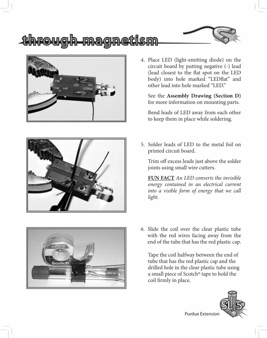
4. Place LED (light-emitting diode) on the circuit board by putting negative (-) lead (lead closest to the flat spot on the LED body) into hole marked “LEDflat” and other lead into hole marked “LED.”
See the Assembly Drawing (Section D) for more information on mounting parts.
Bend leads of LED away from each other to keep them in place while soldering.
5. Solder leads of LED to the metal foil on printed circuit board.
Trim off excess leads just above the solder joints using small wire cutters.
FUN FACT An LED converts the invisible energy contained in an electrical current into a visible form of energy that we call light.
6. Slide the coil over the clear plastic tube with the red wires facing away from the end of the tube that has the red plastic cap. Tape the coil halfway between the end of tube that has the red plastic cap and the drilled hole in the clear plastic tube using a small piece of Scotch® tape to hold the coil firmly in place.
through magnetism

SL-6Purdue Extension
7a. Insert the plastic straw through both 1/4” holes so that straw is centered in the tube.
7b. Bend each end of the straw down toward the coil so the ends touch the tube. Use a piece of Scotch® tape to fasten both ends of the straw to the tube.
8. Thread the red wires through the closest 1/4” hole into the clear plastic tube and bring them out through the open end of the tube.
scoring electricity

SL-7Purdue Extension
9. Place a red wire coming from the coil into one of the holes on the printed circuit board marked “coil.” Place second red wire into other hole marked “coil.” Insert wires far enough for red insulation to touch top of printed circuit board.
See the Assembly Drawing (Section D) for more information on hole markings.
Solder wires to the metal foil on printed circuit board. Be very careful not to overheat wires while soldering as this may cause the insulation to melt.
Trim off excess bare wire just above the solder joints using small wire cutters.
10. Test the LED, diode, and resistor by lightly shaking the assembly back and forth so that the magnet passes through the coil.
The LED should blink each time the magnet passes through the coil.
See Troubleshooting (Section B) if the LED fails to blink.
FUN FACT Every time the magnet passes through the coil, a current is made to flow through the circuit, causing the LED to blink. The LED does not remain lit because there is no way to store the energy produced by the coil…. This is where a capacitor is very useful.
through magnetism

SL-8Purdue Extension
11. Place capacitor on printed circuit board by putting the negative (–) lead into hole marked “cap –” and the positive lead into hole marked “cap +.” Capacitor’s negative lead is the one closest to minus signs printed on side of capacitor body.
See the Assembly Drawing (Section D) for more information on mounting parts.
Bend leads of capacitor away from each other in order to keep them in place while soldering.
Solder leads of capacitor to the metal foil on printed circuit board.
Trim off excess leads just above the solder joints using small wire cutters.
12. Your completed printed circuit board should look like this!
scoring electricity
FUN FACT A capacitor is similar to a rechargeable battery. The magnet, coil, and diode work together to operate like a battery charger when you shake the light. This causes a small current to flow into the capacitor, which causes energy to be stored in the capacitor. This energy is able to power the LED for a short time after you quit shaking the light.

SL-9Purdue Extension
13. Place the printed circuit board inside the clear plastic tube so that the capacitor goes in first.
Pull the extra length of red wire from inside the tube out through the 1/4” hole and wrap it around the tube.
Shake the flashlight for 30 seconds to test the circuit. The LED should light and stay on for many seconds.
14. Using the tape provided with the kit, carefully wrap tape around the coil and red wires. Begin wrapping the tape by starting at the red plastic cap and continuing to just past the 1/4” holes in the side of the clear plastic tube.
HINT: In order to keep the tape flat, it may help if you hold the tape while someone else rotates the tube.
Have fun with your magnet-powered flashlight!
through magnetism
Wrap Tape

SL-10Purdue Extension
If your flashlight is not working correctly at this point, check the following:
o You may not have shaken your flashlight for a full 30 seconds. Try shaking it again while counting out loud to thirty.
o Make sure all component leads are properly soldered to the metal foil.
To Exhibit a Shake Flashlight:
You may exhibit the flashlight on a board (Styrofoam, wood, or other stiff material) measuring no larger than 81/2” x 11”. Mount the flashlight flat on the board, fastening it with string, plastic ties, etc. The flashlight must be able to be removed from the board for judging. If you choose, you do not have to mount the flashlight on a display board to exhibit your project.
b. troubleshooting
Good Solder Joint(shaped like chocolate chip)
Bad Solder Joint Bad Solder Joint
o You may have created a “solder bridge” while soldering. A solder bridge is an unwanted connection, made with solder, between two metal foil areas on the PC Board that are next to each other. A solder bridge can usually be fixed by simply touching the solder bridge with the hot soldering iron tip.
To Exhibit a Poster:
You may create a poster on any topic covered in the Division II Electric manual or on the Electric II CD. The poster should be 22” x 28” and should be designed so that it can be displayed horizontally.
For Either Type of Exhibit:
Attach the “What I Have Learned” page to your exhibit. Complete a 4-H Electric Record Sheet and submit it with your record book.
Questions concerning your exhibit guidelines should be directed to your county Extension office.
scoring electricity
c. to exhibit your project
( if you are not having fun! )

SL-11Purdue Extension
Schematic Drawing
d. drawingsAssembly Drawing
through magnetism

New 03/10
It is the policy of the Purdue University Cooperative Extension Service that all persons have equal opportunity and access to its educational programs, services, activities, and facilities without regard to race, religion, color, sex, age, national origin or ancestry, marital status, parental status, sexual orientation, disability or status as a veteran.
Purdue University is an Affirmative Action institution. This material may be available in alternative formats.
Order or download materials from Purdue Extension • The Education Store
www.the-education-store.com1-888-EXT-INFO • www.extension.purdue.edu