Embed Size (px)
Citation preview

Juan Wang
The University of Nottingham, Ningbo, China
Pin-Qiang Mo
State Key Laboratory for GeoMechanics and Deep Underground Engineering, China University
of Mining and Technology, Xuzhou, China
Hai-Sui Yu
School of Civil Engineering, University of Leeds, Leeds, UK
Shakedown analysis of lined rock cavern for compressed air energy storage
International Geotechnics Symposium cum International Meeting of CSRME 14th Biennial National Congress December 14-17, 2016

Contents
Background
An analytical approach
Results
Conclusions

Background - CAES
Compressed air energy storage (CAES) systems
Lined or unlined rock caverns
Gas pressure: 10 to 30 MPa
Repeated compression-decompression cycles

Background – carven behavior
Stress state ≥ Yield
P0 < Stress state < Yield
∆
=2C (Tresca,
cylindrical case)
>∆ <∆
P0 P1 P2
P1 ≤ Pe
P1 P0
P1 P0 P3
P0
Pe
P2
P3
Pre
P0
Pe …
Elastic shakedown Alternative plasticity (reverse yielding)
Creeping effect is not considered
deformation deformation

The cavern may exhibit plastic strain during each loading cycle as yielding occurs in loading
and unloading processes.
Reverse yielding can lead to low-cycle fatigue of elastic-plastic materials. E.g. failure will
occur in steel specimen after 1000 cycles for a strain range of around 0.02 (Stephens, 1980).
Johansson (2003) suggested to check low-cycle fatigue of steel lining of lined rock cavern.
Low-cycle fatigue needs to be considered in the survivability analysis of rock openings
subjected to multiple attack (Balachandra, 1978).
Shakedown analysis can provide the maximum capacity of a structure against reverse
yielding under cyclic loads based on elastic-plastic theory.
Melan’s shakedown theorem:
For the CAES carven problem, if the stress state after unloading is smaller than the yield
criterion, shakedown will occur; otherwise, reverse yielding will happen.
Background
𝑓(𝜎𝑒 + 𝜎𝑟) ≤ 𝑌

Two layers of isotropic homogenous linear elastic cohesive-frictional
materials (Mohr-Coulomb criterion)
Combine both cylindrical scenario (k=1) and spherical scenario (k=2)
Reverse yielding occurs or not in both materials when fully
unloaded?
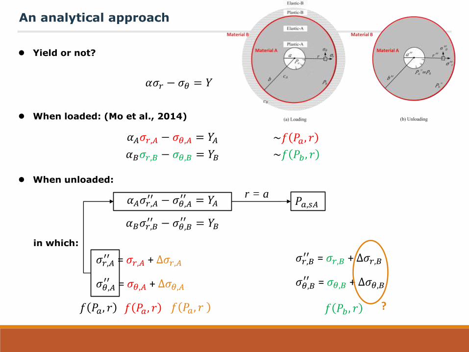
An analytical approach – problem definition
a
(a) Loading
Elastic-B
Elastic-A
Plastic-B
Plastic-A
′′
′′
(b) Unloading
b
r σr
σθ
r′′
σ′′r
σ′′θ
a′′= 0
b′′
cA
cB
Material A
Material B
Material A
Material B

Yield or not?
When loaded: (Mo et al., 2014)
When unloaded:
in which:
An analytical approach
𝛼𝐴𝜎𝑟,𝐴′′ − 𝜎𝜃,𝐴
′′ = 𝑌𝐴
𝛼𝐵𝜎𝑟,𝐵′′ − 𝜎𝜃,𝐵
′′ = 𝑌𝐵
𝛼𝑛 =1 + 𝑠𝑖𝑛𝜙𝑛
1 − 𝑠𝑖𝑛𝜙𝑛
𝑌𝑛 =2𝐶𝑛 𝑐𝑜𝑠𝜙𝑛
1 − 𝑠𝑖𝑛𝜙𝑛
𝛼𝜎𝑟 − 𝜎𝜃 = 𝑌
𝑌 =2𝐶 𝑐𝑜𝑠𝜙
1 − 𝑠𝑖𝑛𝜙
𝛼 =1 + 𝑠𝑖𝑛𝜙
1 − 𝑠𝑖𝑛𝜙
𝛼𝐴𝜎𝑟,𝐴 − 𝜎𝜃,𝐴 = 𝑌𝐴
𝛼𝐵𝜎𝑟,𝐵 − 𝜎𝜃,𝐵 = 𝑌𝐵
~𝑓 𝑎 , 𝑟
~𝑓 𝑏, 𝑟
where n = A or B
?
𝜎𝑟,𝐴′′ = 𝜎𝑟,𝐴 + ∆𝜎𝑟,𝐴
𝜎𝜃,𝐴′′ = 𝜎𝜃,𝐴 + ∆𝜎𝜃,𝐴
𝜎𝑟,𝐵′′ = 𝜎𝑟,𝐵 + ∆𝜎𝑟,𝐵
𝜎𝜃,𝐵′′ = 𝜎𝜃,𝐵 + ∆𝜎𝜃,𝐵
? 𝑓 𝑎 , 𝑟 𝑓 𝑏, 𝑟

For material A:
An analytical approach
∆𝜎𝑟,𝐴 𝑟=𝑎
= − 𝑎′′ − − 𝑎 = 𝑎 − 0
∆𝜎𝑟,𝐴 𝑟=𝑏
= − 𝑏′′ − − 𝑏 = 𝑏 − 𝑏
′′
∆𝜀𝜃,𝐴 𝑟=𝑏
= ∆𝜀𝜃,𝐵 𝑟=𝑏
∆𝜀𝜃,𝐴 𝑟=𝑏
=1
𝑀𝐴−
𝜈𝐴
1 − 𝜈𝐴 2 − 𝑘∆𝜎𝑟,𝐴
𝑟=𝑏+ 1 − 𝜈𝐴 𝑘 − 1 ∆𝜎𝜃,𝐴
𝑟=𝑏
∆𝜀𝜃,𝐵 𝑟=𝑏
=1
𝑀𝐵−
𝜈𝐵
1 − 𝜈𝐵 2 − 𝑘∆𝜎𝑟,𝐵
𝑟=𝑏+ 1 − 𝜈𝐵 𝑘 − 1 ∆𝜎𝜃,𝐵
𝑟=𝑏
∆𝜎𝑟,𝐴 = 𝐴 +𝐵
𝑟𝑘+1− 𝑝0
∆𝜎𝜃,𝐴 = 𝐴 −𝐵
𝑘𝑟𝑘+1− 𝑝0
c
c
For cavity elastic expansion/ contraction from p0:
𝑓 𝑎 , 𝑟
𝑀𝑛 =𝐸𝑛
1 − 𝜈𝑛2 2 − 𝑘
∆𝜎𝑟,𝐴 =
∆𝜎𝜃,𝐴 = 𝑓 𝑎 , 𝑟

Yield or not?
When loaded: (Mo et al., 2014)
When unloaded:
in which:
An analytical approach
𝛼𝐴𝜎𝑟,𝐴′′ − 𝜎𝜃,𝐴
′′ = 𝑌𝐴
𝛼𝐵𝜎𝑟,𝐵′′ − 𝜎𝜃,𝐵
′′ = 𝑌𝐵
𝛼𝜎𝑟 − 𝜎𝜃 = 𝑌
𝛼𝐴𝜎𝑟,𝐴 − 𝜎𝜃,𝐴 = 𝑌𝐴
𝛼𝐵𝜎𝑟,𝐵 − 𝜎𝜃,𝐵 = 𝑌𝐵
~𝑓 𝑎 , 𝑟
~𝑓 𝑏, 𝑟
?
𝜎𝑟,𝐴′′ = 𝜎𝑟,𝐴 + ∆𝜎𝑟,𝐴
𝜎𝜃,𝐴′′ = 𝜎𝜃,𝐴 + ∆𝜎𝜃,𝐴
𝜎𝑟,𝐵′′ = 𝜎𝑟,𝐵 + ∆𝜎𝑟,𝐵
𝜎𝜃,𝐵′′ = 𝜎𝜃,𝐵 + ∆𝜎𝜃,𝐵
? 𝑓 𝑎 , 𝑟 𝑓 𝑏, 𝑟
Yield or not?
When loaded: (Mo et al., 2014)
When unloaded:
in which:
An analytical approach
𝛼𝐴𝜎𝑟,𝐴′′ − 𝜎𝜃,𝐴
′′ = 𝑌𝐴
𝛼𝐵𝜎𝑟,𝐵′′ − 𝜎𝜃,𝐵
′′ = 𝑌𝐵
𝛼𝜎𝑟 − 𝜎𝜃 = 𝑌
𝛼𝐴𝜎𝑟,𝐴 − 𝜎𝜃,𝐴 = 𝑌𝐴
𝛼𝐵𝜎𝑟,𝐵 − 𝜎𝜃,𝐵 = 𝑌𝐵
~𝑓 𝑎 , 𝑟
~𝑓 𝑏, 𝑟
𝜎𝑟,𝐴′′ = 𝜎𝑟,𝐴 + ∆𝜎𝑟,𝐴
𝜎𝜃,𝐴′′ = 𝜎𝜃,𝐴 + ∆𝜎𝜃,𝐴
𝜎𝑟,𝐵′′ = 𝜎𝑟,𝐵 + ∆𝜎𝑟,𝐵
𝜎𝜃,𝐵′′ = 𝜎𝜃,𝐵 + ∆𝜎𝜃,𝐵
? 𝑓 𝑎 , 𝑟 𝑓 𝑎, 𝑟 𝑓 𝑎, 𝑟
𝑎,𝑠𝐴 r = a
𝑓 𝑏, 𝑟

For material B:
An analytical approach
∆𝜎𝑟,𝐵 𝑟=∞
= − 0 − − 0 = 0
∆𝜀𝜃,𝐴 𝑟=𝑏
= ∆𝜀𝜃,𝐵 𝑟=𝑏
∆𝜀𝜃,𝐴 𝑟=𝑏
=1
𝑀𝐴−
𝜈𝐴
1 − 𝜈𝐴 2 − 𝑘∆𝜎𝑟,𝐴
𝑟=𝑏+ 1 − 𝜈𝐴 𝑘 − 1 ∆𝜎𝜃,𝐴
𝑟=𝑏
∆𝜀𝜃,𝐵 𝑟=𝑏
=1
𝑀𝐵−
𝜈𝐵
1 − 𝜈𝐵 2 − 𝑘∆𝜎𝑟,𝐵
𝑟=𝑏+ 1 − 𝜈𝐵 𝑘 − 1 ∆𝜎𝜃,𝐵
𝑟=𝑏
∆𝜎𝑟,𝐵 = 𝐴 +𝐵
𝑟𝑘+1− 𝑝0
∆𝜎𝜃,𝐵 = 𝐴 −𝐵
𝑘𝑟𝑘+1− 𝑝0
c
c
For cavity elastic expansion/ contraction from p0:
𝑓 𝑎 , 𝑟
𝑀𝑛 =𝐸𝑛
1 − 𝜈𝑛2 2 − 𝑘
∆𝜎𝑟,𝐵 =
∆𝜎𝜃,𝐵 = 𝑓 𝑎 , 𝑟
∆𝜎𝑟,𝐵 𝑟=𝑏
= − 𝑏′′ − − 𝑏 = 𝑏 − 𝑏
′′

Yield or not?
When loaded: (Mo et al., 2014)
When unloaded:
in which:
An analytical approach
𝛼𝐴𝜎𝑟,𝐴′′ − 𝜎𝜃,𝐴
′′ = 𝑌𝐴
𝛼𝐵𝜎𝑟,𝐵′′ − 𝜎𝜃,𝐵
′′ = 𝑌𝐵
𝛼𝜎𝑟 − 𝜎𝜃 = 𝑌
𝛼𝐴𝜎𝑟,𝐴 − 𝜎𝜃,𝐴 = 𝑌𝐴
𝛼𝐵𝜎𝑟,𝐵 − 𝜎𝜃,𝐵 = 𝑌𝐵
~𝑓 𝑎 , 𝑟
~𝑓 𝑏, 𝑟
𝜎𝑟,𝐴′′ = 𝜎𝑟,𝐴 + ∆𝜎𝑟,𝐴
𝜎𝜃,𝐴′′ = 𝜎𝜃,𝐴 + ∆𝜎𝜃,𝐴
𝜎𝑟,𝐵′′ = 𝜎𝑟,𝐵 + ∆𝜎𝑟,𝐵
𝜎𝜃,𝐵′′ = 𝜎𝜃,𝐵 + ∆𝜎𝜃,𝐵
? 𝑓 𝑎 , 𝑟 𝑓 𝑎 𝑓 𝑎, 𝑟
𝑎,𝑠𝐴 r = a
𝑓 𝑏, 𝑟

Yield or not?
When loaded: (Mo et al., 2014)
When unloaded:
in which:
An analytical approach
𝛼𝐴𝜎𝑟,𝐴′′ − 𝜎𝜃,𝐴
′′ = 𝑌𝐴
𝛼𝐵𝜎𝑟,𝐵′′ − 𝜎𝜃,𝐵
′′ = 𝑌𝐵
𝛼𝜎𝑟 − 𝜎𝜃 = 𝑌
𝛼𝐴𝜎𝑟,𝐴 − 𝜎𝜃,𝐴 = 𝑌𝐴
𝛼𝐵𝜎𝑟,𝐵 − 𝜎𝜃,𝐵 = 𝑌𝐵
~𝑓 𝑎 , 𝑟
~𝑓 𝑏, 𝑟
𝜎𝑟,𝐴′′ = 𝜎𝑟,𝐴 + ∆𝜎𝑟,𝐴
𝜎𝜃,𝐴′′ = 𝜎𝜃,𝐴 + ∆𝜎𝜃,𝐴
𝜎𝑟,𝐵′′ = 𝜎𝑟,𝐵 + ∆𝜎𝑟,𝐵
𝜎𝜃,𝐵′′ = 𝜎𝜃,𝐵 + ∆𝜎𝜃,𝐵
𝑓 𝑎 , 𝑟 𝑓 𝑎 𝑓 𝑎, 𝑟
𝑎,𝑠𝐴 r = a
𝑓 𝑏, 𝑟 𝑓 𝑎, 𝑟 𝑓 𝑎 , 𝑏, 𝑟
𝑎,𝑠𝐵 r = b
Assume 𝑏′′= 0
𝑎,𝑠 = 𝑚𝑖𝑛 𝑎,𝑠𝐴, 𝑎,𝑠𝐵

Results – numerical validation (cylindrical case)
(a) Cylindrical case: r=a
(b) Cylindrical case: r=b
0 -5 -10 -15 -20 -250 -20 -40 -60 -80 -100 -12015
10
5
0
-5
-10
-15
150
100
50
0
-50
-100
-150
P (kPa)
q/2
(kP
a)
P (kPa)
q/2
(kP
a)
Initial state
Final state
Elastic loading
Plastic loading
Ela
stic
un
load
ing1
1
sinφ2
sinφ1
1sinφ2
1sinφ1
End of loading
(a) Cylindrical case:
r=a
0 -50 -100 -150
150
100
50
0
-50
-100
-150
P (kPa)
q/2
(kP
a)
End of loading
End of unloading
Cyclic load
/ = 4 𝐶A/𝐶B = 50 𝜙A = 𝜙B = 30° 𝐸A = 𝐸B = 100 𝑀
𝜈A = 𝜈B = 0.2 0 = 10𝑘
𝑷𝒂,𝒔/𝑷𝟎 = 𝟐𝟎. 𝟑𝟐
𝑎 = 20.32 0
𝑎 = 20.32 0 × 1.1
𝑝 =𝜎𝑟+ 𝜎𝜃
2; 𝑞 = 𝜎𝑟 − 𝜎𝜃

Results – numerical validation (spherical case)
P (kPa)
0 -100 -200 -300 -400 -500 -600
q (
kPa
)
1000
500
0
-500
-1000
-1500
0 -5 -10 -15 -20 -25
P (kPa)
q (
kPa
)
30
20
10
0
-10
-20
-30
-40
(a) Spherical case: r=a (b) Spherical case: r=b
1
1
2
2
sin3
sin6
2
2
sin3
sin6
Failure line for compression
Failure line for extension
1
1
1
1
sin3
sin6
1
1
sin3
sin6
Unloading
(b) Spherical case:
r=a
P (kPa)
0 -100 -200 -300 -400 -500 -600
q (
kPa
)
1000
500
0
-500
-1000
-1500
End of loading
End of unloading
Cyclic load
/ = 4 𝐶A/𝐶B = 200 𝜙A = 𝜙B = 30° 𝐸A = 𝐸B = 100 𝑀
𝜈A = 𝜈B = 0.2 0 = 10𝑘
𝑷𝒂,𝒔/𝑷𝟎 = 𝟏𝟏𝟓. 𝟎𝟓
𝑎 = 115.05 0
𝑎 = 115.05 0 × 1.1
𝑝 =𝜎𝑟+ 2𝜎𝜃
3; 𝑞 = 𝜎𝑟 − 𝜎𝜃

Results – Lined rock carven
Shakedown limit for a spherical rock cavern with steel lining
(a) (b)
φrock = 37° Erock = 10GPa
νrock = 0.3
a = 2 m
σc,rock = 10 MPa
σy,steel = 355 MPa
Esteel = 198 Gpa
νsteel = 0.3
Shakedown of rock
Shakedown of steel
Rock strength σc (MPa)
Pa
,s /
P0
5
10
15
20
25
30
35
40
0 10 20 30 40 50
Thickness of steel lining (m)
0 0.1 0.2 0.3 0.4 0.5
160
0
20
40
60
80
100
120
140
Pa
,s /
P0
• P0 = 2.5MPa (around 100m depth) • Rock friction angle 𝜙 = 37⁰ • Rock unconfined compression
strength 𝜎𝑐 = 10MPa • Rock cohesion = 𝜎𝑐 1 − 𝑠𝑖𝑛𝜙 /
2𝑐𝑜𝑠𝜙 = 𝜎𝑐/4 • Rock tensile strength = 𝜎𝑐/3 • Rock Young’s Modulus = 10GPa • Rock Poisson’s ratio = 0.3 • Steel yield strength = 355MPa • Steel Young’s Modulus = 198GPA • Steel Poisson’s ratio = 0.32 • Cavern radius = 2m

Analytical solutions for shakedown conditions of a cavity in two layers of cohesive-
frictional materials are developed.
It has been proved by numerical simulations that the proposed analytical solutions
provide admissible cyclic loading conditions for the cavity to avoid reverse yielding.
The shakedown limit pressure of underground lined rock caverns for the CAES systems,
could then be determined by using the developed solutions, which can avoid low-cycle
fatigue.
Further work will be conducted considering concrete lining and better estimation of 𝑏′′.
Concluding remarks

谢 谢
Thank You


![[PPT]Presentación de PowerPoint · Web viewEnergy Storage Methods Energy Storage Mechanical Chemical Electromagnetic Thermal Pumped Hydro Compressed Air (CAES) Flywheel Batteries](https://img.dokumen.tips/doc/110x75/5ac623e37f8b9a333d8e3c59/pptpresentacin-de-powerpoint-viewenergy-storage-methods-energy-storage-mechanical.jpg)