Embed Size (px)
Citation preview

SG 2 AttachmentsSG 2 Roster 12-23-16 2Bryce Hart Resume 11-1-16 3IN16-0501 SC Inspection 7-20-16 6NB16-2808 Moore 10-28-16 7
Part 2 Section 2.3.6.6c1-2 7Part 2 Section 2.3.6.6d 8Part 2 Section 2.3.6.6d-2 11Part 2 Section 2.3.6.9 14
NB16-2809 Moore 10-28-16 15Part 2 S12.2d 15Part 2 Supplement 12 16
Attachment Page 1
Attachment Page 1

SG 2 Roster 12-23-16Attachment Page 2
Attachment Page 2

Bryce A. Hart 1030 Alexander Drive, Temple, PA 19560
Phone: (610) 223-3560 [email protected]
SUMMARY I am a risk engineering technical director with more than 15 years of experience in the insurance equipment breakdown discipline. I have demonstrated collaboration in the development of products to improve our customers risk and meet the needs of our underwriting partners. As a risk engineering manager, I have led my staff to improve their efficiency and productivity while maintaining high quality service. I have proven my abilities in planning and managing projects throughout my career, improving operational efficiencies, team building, and project analysis to determine effective and efficient processes. EXPERIENCE: Zurich North America AVP, Machinery Breakdown Technical Director – March 2016 to Present Regional Risk Engineering Manager – June 2013 to March 2016 Midatlantic Region Portfolio Engineer – December 2006 thru June 2013 Midatlantic Region MB Field Staff – May 2005 thru June 2013
Currently responsible for determining the direction of our Machinery Breakdown team with
respect to emerging risks, new technologies, and ensuring compliance with the rules and regulations of the National Board and the jurisdictions where we perform our service.
Previously served as the Boiler & Machinery Northeast Regional Manager (since June 2013), leading a team of 10 staff members.
Performing monthly conference calls with the regional staff and biweekly individual calls to ensure all appropriate guidance is understood and implemented, and to allow team building within the regional staff.
Directing the ASME and National Board Inspection Code activity within the Northeast Team to meet the jurisdictional inspection requirements of the region.
Developed an education program for our underwriting partners, improving Equipment Breakdown Underwriting technical acumen and aiding in building collaboration with the MB staff.
Developed and implemented methods to ensure compliance with complex regulatory requirements, and empowered his staff to take the lead in their areas of responsibility.
Provided leadership in the servicing of a major EB reinsurance customer, including analyzing their needs for additional services that lead to the development and implementation of our Observe and Report.
As the Portfolio Engineer for the Midatlantic region I provided analysis of prospect and renewal accounts and collaborated with the RE property staff in this region, providing direction and support to our customers and business partners.
Attachment Page 9
Attachment Page 9
Bryce Hart Resume 11-1-16Attachment Page 3
Attachment Page 3

J. C. Penny, Inc. November, 2002 to April 2005 Maintenance Manager Analyzed utility usage and instituted a program that saved more than $20,000 per month in
utility bills. Aggressively pursued solutions to improve the operational accuracy and consistency of the
sortation equipment. Implementing these solutions improved the operational accuracy to more than 99.8%, and reduced the rework caused by these inaccuracies by 90%.
Managed and scheduled a department of eighteen mechanics and housekeepers. This included interviewing, hiring, evaluating and terminating employees, ensuring company policies were adhered to.
Managed the maintenance department and warehouse supplies budgets, both closing the fiscal year below the forecasted budgets. .
R-V Industries, Inc. August, 2000 to October, 2002 Project Manager Managed construction and fabrication projects for this ASME Code shop/specialty metal
fabrication facility. At the height of activity, I managed eight projects with a combined value of $5.1 million in four separate fabrication facilities.
Developed several models for analysis of labor, material, and overhead costs in four manufacturing facilities. Using these models reduced the time for data acquisition by 96%, and increased the project manager productivity by 20%.
Hartford Steam Boiler Inspection & Insurance Company April, 1995 to August, 2000 Program Manager and Inspector Business Unit Manager for the Technical Resource Support Group, performing all duties
required to operate this three person stand-alone business unit. Performed shop and field repair inspections for LJE Brunner and Potts Boiler Repair in
Delaware. Grew the annual revenue 300% in three years. Coordinated and supervised the activities of up to 39 inspectors operating in six countries. MILITARY: U. S. Navy October, 1980 to July, 1994 Chief Electronics Technician/Nuclear Operator Assistant Engineering Officer on Submarine NR-1: Developed a Nuclear Refueling Test Plan
for Bettis Atomic Power Laboratory which included training of test personnel, scheduling of
Attachment Page 10
Attachment Page 10
Bryce Hart Resume 11-1-16Attachment Page 4
Attachment Page 4

ships force and civilian contractor personnel for testing, obtaining necessary test equipment, and supervising the conduct of the testing. Testing completed 7 shifts ahead of schedule.
Education: Industrial Technology Bachelor of Science, Southern Illinois University at Carbondale, December 2000 Credentials: National Board of Boiler & Pressure Vessel Inspectors Commissioned Boiler Inspector #11747 Commissioned Boiler & Pressure Vessel Inspector in Pennsylvania, New Jersey, New York, and Delaware.
Attachment Page 11
Attachment Page 11
Bryce Hart Resume 11-1-16Attachment Page 5
Attachment Page 5

Interpretation IN16-0501
Proposed Interpretation
Inquiry: IN16‐0501
Source: Chris Heichel
Subject: Change of service – LPG & ammonia
Edition: 2015 NBIC
Question 1: Can pressure vessels that were previously used in anhydrous ammonia service be converted to LPG service?
Reply 1: No, except for the following:
ASME containers of 3000 gal (11.4 m3) water
capacity or less used to store anhydrous ammonia,
except for containers used in cargo tank vehicle
service, shall not be converted to LP‐Gas service.
The above paragraph is proposed to be included in
the 2017 NBIC (Part 2, S7.8.6)
SC Vote Passed – Unanimous
NBIC Vote
Attachment Page 12
Attachment Page 12
IN16-0501 SC Inspection 7-20-16Attachment Page 6
Attachment Page 6

National Board of Boiler and Pressure Vessel Inspectors National Board Inspection Code
Submission of Public Review Comment 2017 Draft Edition
Comments Must be Received No Later Than: October 10, 2016 Instructions: If unable to submit electronically, please print this form and fax or mail. Print or type clearly. Date: Commenter Name: Commenter Address: Commenter Phone: Commenter Fax: Commenter Email: Section/Subsection Referenced: Comment/Recommendation: Proposed Solution: □ New Text □ Revise Text □ Delete Text
Source: □ Own Experience/Idea □ Other Source/Article/Code/Standard Submit Form To: Bradley Besserman, NBIC Secretary, The National Board of Boiler & Pressure
Vessel Inspectors, 1055 Crupper Avenue, Columbus, OH 43229, email: [email protected]
PLEASE SUBMIT ONLY ONE COMMENT/RECOMMENDATION PER PAGE Make additional copies as needed
NB Use Only
Commenter No. Issued: Project Committee Referred To:
Comment No. Issued:
Attachment Page 13
Attachment Page 13
NB16-2808 Moore 10-28-16/Part 2 Section 2.3.6.6c1-2Attachment Page 7
Attachment Page 7

National Board of Boiler and Pressure Vessel Inspectors National Board Inspection Code
Submission of Public Review Comment 2017 Draft Edition
Comments Must be Received No Later Than: October 10, 2016 Instructions: If unable to submit electronically, please print this form and fax or mail. Print or type clearly. Date: Commenter Name: Commenter Address: Commenter Phone: Commenter Fax: Commenter Email: Section/Subsection Referenced: Comment/Recommendation: Proposed Solution: □ New Text □ Revise Text □ Delete Text
Source: □ Own Experience/Idea □ Other Source/Article/Code/Standard Submit Form To: Bradley Besserman, NBIC Secretary, The National Board of Boiler & Pressure
Vessel Inspectors, 1055 Crupper Avenue, Columbus, OH 43229, email: [email protected]
PLEASE SUBMIT ONLY ONE COMMENT/RECOMMENDATION PER PAGE Make additional copies as needed
NB Use Only
Commenter No. Issued: Project Committee Referred To:
Comment No. Issued:
Attachment Page 14
Attachment Page 14
NB16-2808 Moore 10-28-16/Part 2 Section 2.3.6.6dAttachment Page 8
Attachment Page 8

Part 2 Section 2.3.6.6 d) Any damage to the cylinder or closures can lead to premature failure. Frequent visual inspection should be made of internal and external surfaces of the cylinder, frame and closures. A thorough examination should be completed if any visually apparent damage is identified or if any excursion beyond design temperature or pressure occurs. In addition, surfaces of the cylinder and closures should be examined by dye penetrant or magnetic particle method at intervals based on vessel remaining life. Closures may require ultrasonic examination of passageways. As part of this inspection guideline for wire wound pressure vessels, frequent inspection, the following items should be reviewed:
1) Verify no change in the process, such as theChanges of the processing fluid, that might adversely impact vessel integrity.
2) Review the vessel manufacturer’sManufacture's inspection recommendations for vessel, closuresclosures, and frame are important. If manufacturer’s recommendations are not available, the owner should obtain recommendations from a recognized wire wound vessel service provider.
3) Verify any repairRepairs to pressure retaining items has beenshould be completed by a National Board authorized service provider having wire wound vessel expertise.
4) Verify overpressureOverpressure protection with appropriate set pressure and capacity is should be provided. Rupture discs are commonly used for pressures exceeding 14,500 psi (100 MPa) to avoid valve seat leakage. Overpressure protection devices are frequently replaced to avoid premature operation.
5) If there are no manufacturer’s recommendations available for the vessel, the following are additional recommended inspections that should be conducted to ensure vessel integrity and safety.
a. Conduct annualAnnual visual and dimensional vessel inspections with should be conducted using liquid penetrant examination of maximum stressed areas to ensure that the surfaces are free of defects. Conduct ultrasonicUltrasonic examination of the vessel should be conducted after every 25% of the design cycle life or every five years, whichever comes first, to detect subsurface cracks. Special attention should be given to the roots of threads and closures using threaded head retention construction. Other geometric discontinuities that are inherent in the design or irregularities resulting from localized corrosion, erosion, or mechanical damage should be carefully examined. This is particularly important for units of monoblock construction.
Attachment Page 15
Attachment Page 15
NB16-2808 Moore 10-28-16/Part 2 Section 2.3.6.6dAttachment Page 9
Attachment Page 9

b. The closure mechanism of the vessel end-closure is may be opened and closed frequently during operation. It The closure mechanism should be closely inspected for freedom of movement and proper contact with its locking elements. Wire wound vessels must have yokeThe presences of yolk-type closures should be verified so the yoke frame will need to beand should be closely inspected on a regular basis
6) Gages, Safety Devices, and Controls
a. Verify that theThe vessel is should be provided with control and monitoring of pressure, temperature, the electrical system, fluid flow, liquid levels, and all variables that are essential for the safe operation of the system. If the vessel is automatically controlled, manual override should be available. Also, safety interlocks should be provided on the vessel closure to prevent vessel pressurization if the vessel closure is not complete and locked.
b. Verify that allAll safety device isolation valves are should be locked open if used.
c. Verify appropriateAppropriate pressure relief devices is should be installed with the setpoint at the lowest pressure possible, consistent with the normal operating pressure, but in no case higher than the design operating pressure of the vessel. Rupture discs are normally considered more suitable for these types of applications, since pressure relief devices operating at pressures above 14,500 psi may tend to leak by their seat.
d. Verify that pressurePressure and temperature of the vessel coolant and vessel wall is should be controlled and monitored. Interlock devices should be installed that will de-energize or depressurize the vessel at established setpoints.
e. Verify audibleAudible and visual alarms are should be installed to indicate unsafe conditions.
Attachment Page 16
Attachment Page 16
NB16-2808 Moore 10-28-16/Part 2 Section 2.3.6.6dAttachment Page 10
Attachment Page 10

National Board of Boiler and Pressure Vessel Inspectors National Board Inspection Code
Submission of Public Review Comment 2017 Draft Edition
Comments Must be Received No Later Than: October 10, 2016 Instructions: If unable to submit electronically, please print this form and fax or mail. Print or type clearly. Date: Commenter Name: Commenter Address: Commenter Phone: Commenter Fax: Commenter Email: Section/Subsection Referenced: Comment/Recommendation: Proposed Solution: □ New Text □ Revise Text □ Delete Text
Source: □ Own Experience/Idea □ Other Source/Article/Code/Standard Submit Form To: Bradley Besserman, NBIC Secretary, The National Board of Boiler & Pressure
Vessel Inspectors, 1055 Crupper Avenue, Columbus, OH 43229, email: [email protected]
PLEASE SUBMIT ONLY ONE COMMENT/RECOMMENDATION PER PAGE Make additional copies as needed
NB Use Only
Commenter No. Issued: Project Committee Referred To:
Comment No. Issued:
Attachment Page 17
Attachment Page 17
NB16-2808 Moore 10-28-16/Part 2 Section 2.3.6.6d-2Attachment Page 11
Attachment Page 11

Part 2 Section 2.3.6.6 d) Any damage to the cylinder or closures can lead to premature failure. Frequent visual inspection should be made of internal and external surfaces of the cylinder, frame and closures. A thorough examination should be completed if any visually apparent damage is identified or if any excursion beyond design temperature or pressure occurs. In addition, surfaces of the cylinder and closures should be examined by dye penetrant or magnetic particle method at intervals based on vessel remaining life. Closures may require ultrasonic examination of passageways. As part of this inspection guideline for wire wound pressure vessels, frequent inspection, the following items should be reviewed:
1) Verify no change in the process, such as theChanges of the processing fluid, that might adversely impact vessel integrity.
2) Review the vessel manufacturer’sManufacture's inspection recommendations for vessel, closuresclosures, and frame are important. If manufacturer’s recommendations are not available, the owner should obtain recommendations from a recognized wire wound vessel service provider.
3) Verify any repairRepairs to pressure retaining items has beenshould be completed by a National Board authorized service provider having wire wound vessel expertise.
4) Verify overpressureOverpressure protection with appropriate set pressure and capacity is should be provided. Rupture discs are commonly used for pressures exceeding 14,500 psi (100 MPa) to avoid valve seat leakage. Overpressure protection devices are frequently replaced to avoid premature operation.
5) If there are no manufacturer’s recommendations available for the vessel, the following are additional recommended inspections that should be conducted to ensure vessel integrity and safety.
a. Conduct annualAnnual visual and dimensional vessel inspections with should be conducted using liquid penetrant examination of maximum stressed areas to ensure that the surfaces are free of defects. Conduct ultrasonicUltrasonic examination of the vessel should be conducted after every 25% of the design cycle life or every five years, whichever comes first, to detect subsurface cracks. Special attention should be given to the roots of threads and closures using threaded head retention construction. Other geometric discontinuities that are inherent in the design or irregularities resulting from localized corrosion, erosion, or mechanical damage should be carefully examined. This is particularly important for units of monoblock construction.
Attachment Page 18
Attachment Page 18
NB16-2808 Moore 10-28-16/Part 2 Section 2.3.6.6d-2Attachment Page 12
Attachment Page 12

b. The closure mechanism of the vessel end-closure is may be opened and closed frequently during operation. It The closure mechanism should be closely inspected for freedom of movement and proper contact with its locking elements. Wire wound vessels must have yokeThe presences of yolk-type closures should be verified so the yoke frame will need to beand should be closely inspected on a regular basis
6) Gages, Safety Devices, and Controls
a. Verify that theThe vessel is should be provided with control and monitoring of pressure, temperature, the electrical system, fluid flow, liquid levels, and all variables that are essential for the safe operation of the system. If the vessel is automatically controlled, manual override should be available. Also, safety interlocks should be provided on the vessel closure to prevent vessel pressurization if the vessel closure is not complete and locked.
b. Verify that allAll safety device isolation valves are should be locked open if used.
c. Verify appropriateAppropriate pressure relief devices is should be installed with the setpoint at the lowest pressure possible, consistent with the normal operating pressure, but in no case higher than the design operating pressure of the vessel. Rupture discs are normally considered more suitable for these types of applications, since pressure relief devices operating at pressures above 14,500 psi may tend to leak by their seat.
d. Verify that pressurePressure and temperature of the vessel coolant and vessel wall is should be controlled and monitored. Interlock devices should be installed that will de-energize or depressurize the vessel at established setpoints.
e. Verify audibleAudible and visual alarms are should be installed to indicate unsafe conditions.
Attachment Page 19
Attachment Page 19
NB16-2808 Moore 10-28-16/Part 2 Section 2.3.6.6d-2Attachment Page 13
Attachment Page 13

National Board of Boiler and Pressure Vessel Inspectors National Board Inspection Code
Submission of Public Review Comment 2017 Draft Edition
Comments Must be Received No Later Than: October 10, 2016 Instructions: If unable to submit electronically, please print this form and fax or mail. Print or type clearly. Date: Commenter Name: Commenter Address: Commenter Phone: Commenter Fax: Commenter Email: Section/Subsection Referenced: Comment/Recommendation: Proposed Solution: □ New Text □ Revise Text □ Delete Text
Source: □ Own Experience/Idea □ Other Source/Article/Code/Standard Submit Form To: Bradley Besserman, NBIC Secretary, The National Board of Boiler & Pressure
Vessel Inspectors, 1055 Crupper Avenue, Columbus, OH 43229, email: [email protected]
PLEASE SUBMIT ONLY ONE COMMENT/RECOMMENDATION PER PAGE Make additional copies as needed
NB Use Only
Commenter No. Issued: Project Committee Referred To:
Comment No. Issued:
Attachment Page 20
Attachment Page 20
NB16-2808 Moore 10-28-16/Part 2 Section 2.3.6.9Attachment Page 14
Attachment Page 14

National Board of Boiler and Pressure Vessel Inspectors National Board Inspection Code
Submission of Public Review Comment 2017 Draft Edition
Comments Must be Received No Later Than: October 10, 2016 Instructions: If unable to submit electronically, please print this form and fax or mail. Print or type clearly. Date: Commenter Name: Commenter Address: Commenter Phone: Commenter Fax: Commenter Email: Section/Subsection Referenced: Comment/Recommendation: Proposed Solution: □ New Text □ Revise Text □ Delete Text
Source: □ Own Experience/Idea □ Other Source/Article/Code/Standard Submit Form To: Bradley Besserman, NBIC Secretary, The National Board of Boiler & Pressure
Vessel Inspectors, 1055 Crupper Avenue, Columbus, OH 43229, email: [email protected]
PLEASE SUBMIT ONLY ONE COMMENT/RECOMMENDATION PER PAGE Make additional copies as needed
NB Use Only
Commenter No. Issued: Project Committee Referred To:
Comment No. Issued:
Attachment Page 21
Attachment Page 21
NB16-2809 Moore 10-28-16/Part 2 S12.2dAttachment Page 15
Attachment Page 15
National Board of Boiler and Pressure Vessel Inspectors National Board Inspection Code
Submission of Public Review Comment 2017 Draft Edition
Comments Must be Received No Later Than: October 10, 2016 Instructions: If unable to submit electronically, please print this form and fax or mail. Print or type clearly. Date: Commenter Name: Commenter Address: Commenter Phone: Commenter Fax: Commenter Email: Section/Subsection Referenced: Comment/Recommendation: Proposed Solution: □ New Text □ Revise Text □ Delete Text
Source: □ Own Experience/Idea □ Other Source/Article/Code/Standard Submit Form To: Bradley Besserman, NBIC Secretary, The National Board of Boiler & Pressure
Vessel Inspectors, 1055 Crupper Avenue, Columbus, OH 43229, email: [email protected]
PLEASE SUBMIT ONLY ONE COMMENT/RECOMMENDATION PER PAGE Make additional copies as needed
NB Use Only
Commenter No. Issued: Project Committee Referred To:
Comment No. Issued:
Attachment Page 22
Attachment Page 22
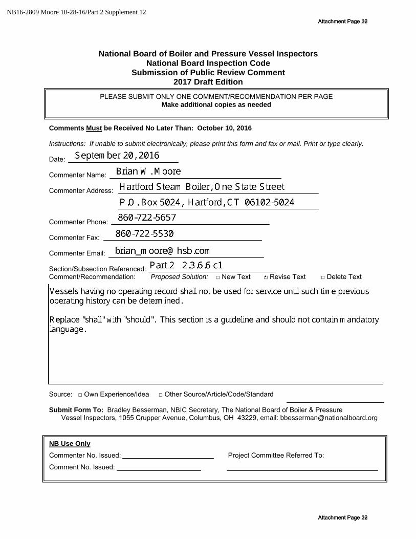
NB16-2809 Moore 10-28-16/Part 2 Supplement 12Attachment Page 16
Attachment Page 16

Part 2 Supplement 12 Replace mandatory "shall" with nonmandatory "should" in all places listed below. S12.3 b) Portable LCDSV installations with no permanent remote fill connection: Warning: LCDSVs shall should not be filled indoors… 4) Are provided with a pathway that provides a smooth rolling surface to the outdoor, unenclosed fill area. There shall should not be any stairs or other than minimal inclines in the pathway. S12.5 A continuous gas detection system shall should be provided in the room or area where container systems are filled and used, in areas where the heavier that air gas can congregate and in below grade outdoor locations. Carbon dioxide (CO2) sensors shall should be provided within 12 inches (305mm) of the floor in the area where the gas is most likely to accumulate or leaks are most likely to occur. The system shall should be designed to detect and notify at a low level alarm and high level alarm. a) The threshold for activation of the low level alarm shall should not exceed a carbon
dioxide concentration of 5,000 ppm (9,000 mg/m3) Time Weighted Average (TWA) over 8 hours. When carbon dioxide is detected at the low level alarm, the system shall should activate a signal at a normally attended location within the building.
b) The threshold for activation of the high level alarm shall should not exceed a carbon dioxide concentration 30,000 ppm (54,000 mg/m3). When carbon dioxide is detected at the high level alarm, the system shall should activate an audible and visual alarm at a location approved by the jurisdiction having authority.
S12.6 SIGNAGE The inspection should verify that hazard identification signs are posted at the entrance to the building, room, enclosure, or enclosed area where the container is located. The warning sign shall should be at least 8 in (200mm) wide and 6 in. (150mm) high and indicate… S12.7 VALVES, PIPING, TUBING AND FITTINGS a) 1) Components shall should be rated for the operational temperatures and pressures encountered in the applicable circuit of the system. a) 2) All valves and fittings used on the LCDSV shall should be rated for the maximum allowable working pressure(MAWP) stamped on the tank. a) 3) All piping, hoses and tubing used in the LCDSV system shall should be rated for the working pressure of the applicable circuit in the system and have a burst pressure rating of at least four times the MAWP of the piping, hose or tubing.
Attachment Page 23
Attachment Page 23
NB16-2809 Moore 10-28-16/Part 2 Supplement 12Attachment Page 17
Attachment Page 17

b) Relief Valves – The inspection should verify that each LCDSV shall should have at least one ASME/NB stamped & certified relief valve with a pressure setting at or below the MAWP of the tank. The relief valve shall should be suitable for the temperatures and flows experienced during relief valve operation. The minimum relief valve capacity shall should be designated by the manufacturer. Additional relief valves that do not require ASME stamps may be added per Compressed Gas Association pamphlet, CGA S-1.3 Pressure Relief Device Standards Part 3, Stationary Storage Containers for Compressed Gases, recommendations. Discharge lines from the relief valves shall should be sized in accordance with NBIC Part 2, Tables S12.7-a and S12.7-b. Note: Due to the design of the LCDSV the discharge line may be smaller in diameter than the relief valve outlet size. Caution: Company’s and or individuals filling or refilling LCDSV’s shall should be responsible for utilizing fill equipment that is acceptable to the manufacturer to prevent over pressurization of the vessel. c) Isolation Valves – The inspection should verify that each LCDSV shall should have an isolation valve installed on the fill line and tank discharge, or gas supply line in accordance with the following requirements:
1) Isolation valves shall should be located on the tank or at an accessible point as near to the storage tank a possible. 2) All valves shall should be designed or marked to indicate clearly whether they are open or closed. 3) All valves shall should be capable of being locked or tagged in the closed position for servicing. 4) Gas supply and liquid CO2 fill valves shall should be clearly marked for easy identification.
d) Safety Relief/Vent Lines – The inspection, where possible, should verify the integrity of the pressure relief/vent line from the pressure relief valve to outside vent line discharge fitting. All connections shall should be securely fastened to the LCDSV. The minimum size and length of the lines shall should be in accordance with NBIC Part 2, Tables S12.7-a and S12.7-b. Fittings or other connections may result in a localized reduction in diameter have been factored into the lengths given by the NBIC Part 2, Tables S12.7-a and S12.7-b. Table S12.7M-b Note: Due to the design of the LCDSV, the discharge line may be smaller in diameter than the relief valve outlet size but shall should not be smaller than that shown in tables NBIC Part 2, S12.7-a and -b.
Attachment Page 24
Attachment Page 24
NB16-2809 Moore 10-28-16/Part 2 Supplement 12Attachment Page 18
Attachment Page 18

COMMENT: The above note is immediately after the metric Tables S12.7M-a and -b, but the referenced tables are the customary units S12.7-a and -b. This appears to be a mistake.
Attachment Page 25
Attachment Page 25
NB16-2809 Moore 10-28-16/Part 2 Supplement 12Attachment Page 19
Attachment Page 19