Embed Size (px)
DESCRIPTION
sf_20024.pdf
Citation preview
Quick Start Guide
Guía de inicio rápidoGuida di riferimento rapido
KurzanleitungGuide de démarrage rapide
Cisco Small Business
200 Series Smart Switches
Downloaded from www.Manualslib.com manuals search engine
2 200 Series Smart Switches
Welcome
Thank you for choosing the Cisco 200 Series Smart Switch, a Cisco Small Business network communications device. This device is designed to be operational right out-of-the-box as a standard bridge. In the default configuration, it will forward packets between connecting devices after powered up.
Package Contents
• Cisco SF 200-24, SF 200-24P, SF 200-48, SF 200-48P, SG 200-18, SG 200-26, SG 200-26P, SG 200-50, or SG 200-50P Smart Switch.
• Rackmount Kit.
• Power Cord.
• This Quick Start Guide.
• Product CD.
This guide will familiarize you with the layout of the smart switch and describe how to deploy the device in your network. For additional information, see www.cisco.com/smb.
Mounting the Cisco Switch
There are two ways to mount the switch:
• Set the switch on a flat surface.
• Mount the switch in a standard rack (1 rack unit high).
Do not mount the device in a location where any of the following conditions exist:
High Ambient Temperature—The ambient temperature must not exceed 104 degrees Fahrenheit (40 degrees Centigrade).
Reduced Air Flow—Both side panels must be unobstructed to prevent overheating.
Mechanical Overloading—The device must be level, stable, and secure to prevent it from sliding or shifting out-of-position.
Circuit Overloading—Adding the device to the power outlet must not overload that circuit.
1
Downloaded from www.Manualslib.com manuals search engine
200 Series Smart Switches 3
Rack-Mount Placement
If your switch is rack-mount capable, it will come with a rack-mount kit. To rack-mount the switch in any standard rack, attach the brackets to the sides of the switch with the supplied hardware and secure the brackets.
CAUTION For stability, load the rack from the bottom to the top, with the heaviest devices on the bottom. A top-heavy rack is likely to be unstable and might tip over.
Connecting Network Devices
To connect the smart switch to the network:
STEP 1 Connect the Ethernet cable to the Ethernet port of a computer, printer, network storage, or other network device.
STEP 2 Connect the other end of the Ethernet cable to one of the numbered smart switch Ethernet ports.
The LED of the port lights if the device connected is active. Refer to Features of the Cisco Small Business Smart Switch, page 7 for details about the different ports and LEDs on each switch.
STEP 3 Repeat Step 1 and Step 2 for each device you want to connect to the smart switch.
NOTE Cisco recommends using Cat5 or better cable for Gigabit connectivity. When you connect your network devices, do not exceed the maximum cabling distance of 328 feet (100 meters). It can take up to one minute for attached devices or the LAN to be operational after they are connected. This is normal behavior.
Power over Ethernet Considerations
If your switch is one of the Power over Ethernet (PoE) models, consider the following power requirement:
• As a Power Sourcing Equipment (PSE) device, the switch can deliver a maximum of 15.4 Watts per PoE port to a Powered Device (PD).
2
Downloaded from www.Manualslib.com manuals search engine

4 200 Series Smart Switches
PoE is available on the following ports:
Use the following table to determine the total power budget available for all devices on your switch.
Configuring the Cisco Small Business Smart Switch
Before You Begin
Verify that a computer with Microsoft Internet Explorer (version 6 or higher) or Firefox (version 2.0 or higher) is available.
Accessing and Managing Your Switch Using the Web-Based Interface
In order to access the switch with a web-based interface, you must know the management IP address of the switch. The default configuration of the switch is to use its factory default IP address of 192.168.1.254 until it has obtained an IP address from a DHCP server, or it has been changed to a static IP address.
When the switch is using the factory default IP address, its System LED flashes continuously. When the switch is using a DHCP assigned IP address or an administrator configured static IP address, the System LED lights steady.
NOTE If the smart switch IP address is changed, either by a DHCP server or manually, your access to the smart switch will be lost and you must use the new IP address to configure the device.
To configure the smart switch:
STEP 1 Power on the computer and the switch.
STEP 2 Connect the computer to the switch. You can connect to the same IP subnet as the switch by connecting them directly with an
Model Ports
SF 200-24P and SG 200-26P 1—6 and 13—18
SF 200-48P and SG 200-50P 1—12 and 25—36
Model Power Dedicated to PoE
SF 200-24P 100 Watts
SF 200-48P 180 Watts
SG 200-26P 100 Watts
SG 200-50P 180 Watts
3
Downloaded from www.Manualslib.com manuals search engine
200 Series Smart Switches 5
Ethernet cable, or by connecting to the same LAN where the switch is located through other switches. You can also connect your computer to the switch from another IP subnet through one or more IP routers.
STEP 3 Set up the IP configuration on your computer.
a. If the switch is using the default static IP address of 192.168.1.254, you must choose an IP address in the range of 192.168.1.1—192.168.1.253 that is not already being used by another device.
b. If the IP addresses will be assigned by DHCP, make sure your DHCP server is running and can be reached from the switch and the computer. You might need to disconnect and reconnect the devices for them to discover their new IP addresses from the DHCP server.
NOTE Details on how to change the IP address on your computer depend upon the type of architecture and operating system you are using. See your computer’s local Help and Support functionality and search for “IP Addressing.”
STEP 4 Open a Web browser window. If you are prompted to install an Active-X plug-in when connecting to the device, follow the prompts to accept the plug-in.
STEP 5 Enter the switch IP address in the address bar and press Enter. For example, http://192.168.1.254.
The Smart Switch Login page displays.
STEP 6 Enter the login information:
Username is cisco
Default password is cisco (passwords are case sensitive)
STEP 7 If this is the first time that you have logged on with the default username and password, the Change Password page opens. Enter a new administrator password and then click Apply.
CAUTION Make sure that any configuration changes that you made are saved before exiting from the web-based interface by clicking on the Save icon, then clicking Apply. Exiting before you save your configuration will result in all changes being lost.
The Getting Started window displays. You are now ready to configure the switch. Refer to the Cisco Small Business Smart Switch Administration Guide for further information.
Downloaded from www.Manualslib.com manuals search engine

6 200 Series Smart Switches
Troubleshoot Your Connection
If you cannot access your switch from the web-based interface, the switch might not be reachable from your computer. You can test network connections by using the ping command. The following section shows how to use “ping” in a Windows environment:
STEP 1 Open a command window by using Start > Run and enter cmd.
STEP 2 At the Command window prompt enter ping and the smart switch IP address. For example ping 192.168.1.254 (the default IP address of the smart switch).
If you can reach the switch, you should get a reply similar to the following:
Pinging 192.168.1.254 with 32 bytes of data:Reply from 192.168.1.254: bytes=32 time<1ms TTL=128
If you cannot reach the switch, you should get a reply similar to the following:
Pinging 192.168.1.254 with 32 bytes of data:Request timed out.
Possible Causes and Resolutions
No Power:
Power up the switch and your computer if they are turned off.
Bad Ethernet connection:
Check the LEDs for proper indications. Check the connectors of the Ethernet cable to ensure they are firmly plugged into the switch and your computer.
Wrong or conflicting IP address:
Make sure that you are using the correct IP address of the switch. You can verify the current IP address of the switch with your network administrator. The System LED provides an indication of where the switch received the IP address, see Section 4 for details.
Make sure that no other device is using the same IP address as the switch.
No IP route:
If the switch and your computer are in different IP subnets, you need one or more routers to route the packets between the two subnets.
Downloaded from www.Manualslib.com manuals search engine

200 Series Smart Switches 7
Unusually long access time:
Due to the spanning tree loop detection logic, adding new connections might take 30 to 60 seconds for the affected interfaces and/or LAN to become operational.
Features of the Cisco Small Business Smart Switch
This section describes the exterior of the smart switches including ports, LEDs, and connections. Not all models will have all of the features described.
Ports
RJ-45 Ethernet Ports—Use these ports to connect network devices, such as computers, printers, and access points, to the switch.
MiniGBIC (if present)—The miniGBIC (gigabit interface converter) ports are connection points for miniGBIC modules, so the smart switch can uplink to other switches by using optical fiber.
• MiniGBIC ports are compatible with Cisco miniGBIC modules MGBSX1, MGBLH1, MGBLX1, MGBBX1, MFELX1, MFEFX1, and MFEBX1, as well as other brands of miniGBIC modules.
• MiniGBIC interface is a combination port, shared with one other RJ-45 interface. When the MiniGBIC is active, the adjacent RJ-45 port is disabled.
• The LEDs of the corresponding RJ-45 port flashes green to respond to the miniGBIC interface traffic.
4
Downloaded from www.Manualslib.com manuals search engine

8 200 Series Smart Switches
LEDs
System LED—(Green) Lights steady when the switch is powered on, and flashes when booting, performing self tests, and acquiring an IP address. If the LED flashes amber, the switch has detected a hardware failure.
LINK/ACT LED—(Green) Located on the left of the port. Lights steady when a link between the corresponding port and another device is detected. Flashes when the port is passing traffic.
NOTE The System and LINK/ACT LEDs are on each model of the switch. The following LEDs are only present on switch models that have those capabilities:
PoE (if present)—(Amber) Located on the right of the port. Lights steady to indicate that power is being supplied to a device attached to the corresponding port.
100M LED (if present)—(Green) Located on the right of the port. Lights steady when another device is connected to the port, is powered on, and a 100 Mbps link is established between the devices. When the LED is off, the connection speed is under 100 Mbps or nothing is cabled to the port.
Gigabit LED (if present)—(Green) Located on the right of the port. Lights steady when another device is connected to the port, is powered on, and a 1000 Mbps link is established between the devices. When the LED is off, the connection speed is under 1000 Mbps or nothing is cabled to the port.
MiniGBIC (if present)—(Green) Located on the right of the port. Lights steady when a connection is made through the shared RJ-45 port. Flashes when the port is passing traffic.
Additional Features
The switch might also have a reset button. The switch can be reset by inserting a pin or paper clip into the reset opening. See “Returning the Device to the Factory Default Settings” for details.
Downloaded from www.Manualslib.com manuals search engine
200 Series Smart Switches 9
Back Panel
The power port is located on the back panel of the smart switch.
Returning the Device to the Factory Default Settings
To use the Reset button to reboot or reset the smart switch, do the following:
• To reboot the smart switch, press the Reset button for less than 10 seconds.
• To restore the smart switch configuration to the factory default settings:
1. Disconnect the smart switch from the network or disable all DHCP servers on your network.
2. With the power on, press and hold the Reset button for more than 10 seconds.
5
Downloaded from www.Manualslib.com manuals search engine

10 200 Series Smart Switches
Where to Go From Here
Support
Cisco Small Business Support Community
www.cisco.com/go/smallbizsupport
Cisco Small Business Support and Resources
www.cisco.com/go/smallbizhelp
Phone Support Contacts www.cisco.com/en/US/support/tsd_cisco_ small_business_support_center_contacts.html
Cisco Small Business Firmware Downloads
www.cisco.com/go/smallbizfirmware
Select a link to download firmware for Cisco Small Business Products. No login is required.
Downloads for all other Cisco Small Business products, including Network Storage Systems, are available in the Download area on Cisco.com at www.cisco.com/go/software (registration/login required).
Product Documentation
Cisco Small Business Smart Switches
www.cisco.com/go/smallbizsmartswitches
200 Series Smart Switches Quick Start Guide
www.cisco.com/en/US/docs/switches/lan/csbss/sf20x_sg20x/quick_start/78-19501-01.pdf
200 Series Smart Switches Administration Guide
www.cisco.com/en/US/docs/switches/lan/csbss/sf20x_sg20x/administration_guide/OL-22849-01.pdf
Regulatory, Compliance, and Safety Information
www.cisco.com/en/US/docs/switches/lan/csbms/sfe2000/release/notes/Class_A_Switches_RCSI.pdf
Warranty Information www.cisco.com/go/warranty
Cisco Small Business
Cisco Partner Central for Small Business (Partner Login Required)
www.cisco.com/web/partners/sell/smb
Cisco Small Business Home www.cisco.com/smb
6
Downloaded from www.Manualslib.com manuals search engine

Americas HeadquartersCisco Systems, Inc.170 West Tasman DriveSan Jose, CA 95134-1706USAhttp://www.cisco.comSmall Business Support US: 1-866-606-1866 (Toll Free, 24/7)Small Business Support Global Contact Numbers
Cisco, Cisco Systems, the Cisco logo, and the Cisco Systems logo are registered trademarks
or trademarks of Cisco and/or its affiliates in the United States and certain other countries. Allother trademarks mentioned in this document or website are the property of their respective
owners. The use of the word partner does not imply a partnership relationship between Cisco
and any other company. (1002R)
© 2010 Cisco Systems, Inc. All rights reserved.
Downloaded from www.Manualslib.com manuals search engine

Guía de inicio rápido
Cisco para pequeñas empresas
200 Series Smart Switches
Downloaded from www.Manualslib.com manuals search engine

200 Series Smart Switches 13
Bienvenido
Gracias por elegir el Cisco 200 Series Smart Switch, un dispositivo de comunicaciones de red Cisco Small Business. Este dispositivo está diseñado y configurado de fábrica para que funcione como un puente estándar. En la configuración predeterminada, reenviará paquetes entre los dispositivos de conexión tras el encendido.
Contenido de la caja
• Cisco SF 200-24, SF 200-24P, SF 200-48, SF 200-48P, SG 200-18, SG 200-26, SG 200-26P, SG 200-50 o SG 200-50P Smart Switch.
• Kit de montaje en bastidor.
• Cable de alimentación eléctrica.
• Esta guía de inicio rápido.
• CD del producto.
Esta guía lo ayudará a familiarizarse con el diseño del switch inteligente y describirá cómo implementar el dispositivo en la red. Para obtener más información, vaya a www.cisco.com/smb.
Montaje del switch de Cisco
Existen dos maneras para montar el switch:
• Colocar el switch sobre una superficie plana.
• Instalar el switch montado en un bastidor estándar (una unidad de bastidor de alto).
No monte el dispositivo en una ubicación donde se den una de las siguientes condiciones:
Alta temperatura ambiente: la temperatura ambiente no debe superar los 104 grados Fahrenheit (40 grados centígrados).
Circulación de aire reducida: ambos paneles laterales deben estar libres para evitar el sobrecalentamiento.
Sobrecarga mecánica: el dispositivo debe estar nivelado, estable y protegido para evitar que se deslice o que cambie de posición.
Sobrecarga del circuito: al agregar el dispositivo a un tomacorriente no se debe sobrecargar ese circuito.
1
Downloaded from www.Manualslib.com manuals search engine

14 200 Series Smart Switches
Ubicación de montaje en bastidor
Si el switch se puede montar en un bastidor, incluirá un kit de montaje en bastidor. Para montar el switch en un bastidor estándar, conecte los soportes a los costados del switch con el hardware suministrado y ajuste los soportes.
PRECAUCIÓN Para mayor estabilidad, cargue el bastidor desde abajo hacia arriba con los dispositivos más pesados en la parte inferior. Si coloca un bastidor con mucho peso en la parte superior es probable que se desestabilice y se caiga.
Conexión de dispositivos de red
Para conectar el switch inteligente a la red:
PASO1 Conecte el cable Ethernet al puerto Ethernet de una computadora, impresora, un dispositivo de almacenamiento de red u otro dispositivo de red.
PASO2 Conecte el otro extremo del cable Ethernet a uno de los puertos Ethernet numerados del switch inteligente.
El indicador LED del puerto se enciende si el dispositivo conectado está activo. Consulte Características del Cisco Small Business Smart Switch, página 18 para obtener más información sobre los distintos puertos e indicadores LED de cada switch.
PASO3 Repita el Paso 1 y el Paso 2 para cada dispositivo que desee conectar al switch inteligente.
NOTA Cisco recomienda usar Cat5 o un cable superior para la conectividad Gigabit. Al conectar los dispositivos de red, no exceda la distancia de cableado máxima de 328 pies (100 metros). Los dispositivos adjuntos o la red LAN pueden tardar un minuto en funcionar luego de ser conectados. Éste es el comportamiento normal.
Consideraciones de la alimentación por Ethernet
Si el switch es uno de los modelos de alimentación por Ethernet (PoE), tenga en cuenta los siguientes requisitos de alimentación:
• Como dispositivo de equipamiento de fuente de alimentación (PSE), el switch puede ofrecer un máximo de 15,4 vatios por puerto PoE a un dispositivo alimentado (PD).
2
Downloaded from www.Manualslib.com manuals search engine

200 Series Smart Switches 15
PoE está disponible en los siguientes puertos:
Use la siguiente tabla para determinar el presupuesto de alimentación total que está disponible para todos los dispositivos de su switch.
Configuración del Cisco Small Business Smart Switch
Antes de comenzar
Asegúrese de contar con una computadora con Microsoft Internet Explorer (versión 6 o superior) o Firefox (versión 2.0 o superior).
Acceso y administración del switch mediante la interfaz basada en la Web
Para obtener acceso al switch con una interfaz basada en la Web, deberá conocer la dirección IP de administración del switch. La configuración predeterminada del switch es usar la dirección IP predeterminada de fábrica de 192.168.1.254 hasta tanto se obtenga una dirección IP de un servidor DHCP o hasta que se haya cambiado a una dirección IP estática.
Si el switch usa la dirección IP predeterminada de fábrica, el indicador LED del sistema parpadea continuamente. Si el switch usa una dirección IP asignada por DHCP, o una dirección IP estática configurada por el administrador, el indicador LED del sistema permanece encendido.
NOTA Si se cambia la dirección IP del switch inteligente, ya sea mediante un servidor DHCP o manualmente, perderá la posibilidad de acceder al switch inteligente y deberá usar una nueva dirección IP para configurar el dispositivo.
Modelo Puertos
SF 200-24P y SG 200-26P 1—6 y 13—18
SF 200-48P y SG 200-50P 1—12 y 25—36
Modelo Energía dedicada a PoE
SF 200-24P 100 vatios
SF 200-48P 180 vatios
SG 200-26P 100 vatios
SG 200-50P 180 vatios
3
Downloaded from www.Manualslib.com manuals search engine

16 200 Series Smart Switches
Para configurar el switch inteligente:
PASO1 Encienda la computadora y el switch.
PASO2 Conecte la computadora al switch. Puede conectarla a la misma subred IP que el switch al conectarlos directamente con un cable Ethernet, o al conectarlos a la misma red LAN donde se encuentra el switch a través de otros switches. También puede conectar la computadora al switch desde otra subred IP a través de uno o más routers IP.
PASO3 Establezca la configuración IP en la computadora.
a. Si el switch usa la dirección IP estática predeterminada de 192.168.1.254, debe elegir una dirección IP en el rango de 192.168.1.1—192.168.1.253 que no esté siendo usada por otro dispositivo.
b. Si las direcciones IP se asignarán a través de DHCP, asegúrese de que el servidor DHCP esté en funcionamiento y que pueda acceder a él desde el switch y la computadora. Es posible que deba desconectar y volver a conectar los dispositivos para que detecten las nuevas direcciones IP del servidor DHCP.
NOTA La información acerca de cómo cambiar la dirección IP de su computadora depende del tipo de arquitectura y sistema operativo que utilice. Use la funcionalidad de Ayuda y Soporte local de su computadora y busque “IP Addressing” (Asignación de direcciones IP).
PASO4 Abra una ventana del navegador Web. Si se le solicita que instale un complemento Active-X al conectar el dispositivo, siga las instrucciones para aceptar el complemento.
PASO5 Introduzca la dirección IP del switch en la barra de direcciones y presione Enter (Intro). Por ejemplo, http://192.168.1.254.
Aparece la página de inicio de sesión del Smart Switch.
PASO6 Introduzca la información de inicio de sesión:
El nombre de usuario es cisco
La contraseña predeterminada es cisco (las contraseñas distinguen entre mayúsculas y minúsculas)
PASO7 Si es la primera vez que inicia sesión con el nombre de usuario y la contraseña predeterminados, se abre la página Change Password (Cambiar contraseña). Introduzca una nueva contraseña de administrador y, a continuación, haga clic en Apply (Aplicar).
Downloaded from www.Manualslib.com manuals search engine

200 Series Smart Switches 17
PRECAUCIÓN Asegúrese de guardar todos los cambios de configuración que realice antes de salir de la interfaz basada en la Web, al hacer clic en el ícono Save (Guardar) y luego en Apply (Aplicar). Si sale antes de guardar la configuración, se perderán todos los cambios.
Se muestra la ventana Getting Started (Inicio). Ahora está listo para configurar el switch. Para obtener más información, consulte la Guía de administración del Cisco Small Business Smart Switch.
Solución de problemas de conexión
Si no puede obtener acceso al switch desde la interfaz basada en la Web, es posible que no pueda acceder al switch desde la computadora. Puede probar las conexiones de red al utilizar el comando ping. El siguiente ejemplo muestra cómo usar el “ping” en un entorno Windows:
PASO1 Abra una ventana de comando al utilizar Start (Inicio) > Run (Ejecutar) y escriba cmd.
PASO2 En la ventana Command (Comando), escriba ping y la dirección IP de switch inteligente. Por ejemplo, el comando ping 192.168.1.254 (la dirección IP predeterminada del switch inteligente).
Si puede obtener acceso al switch, debe obtener una respuesta similar a la siguiente:
Pinging 192.168.1.254 with 32 bytes of data:Reply from 192.168.1.254: bytes=32 time<1ms TTL=128
Si no puede obtener acceso al switch, debe obtener una respuesta similar a la siguiente:
Pinging 192.168.1.254 with 32 bytes of data:Request timed out.
Posibles causas y resoluciones
Sin alimentación:
Encienda el switch y la computadora si están apagados.
Mala conexión Ethernet:
Compruebe los indicadores LED para obtener las instrucciones adecuadas. Revise los conectores del cable Ethernet para asegurarse de que estén firmemente conectados al switch y la computadora.
Downloaded from www.Manualslib.com manuals search engine

18 200 Series Smart Switches
Dirección IP incorrecta o en conflicto:
Asegúrese de estar usando la dirección IP correcta del switch. Puede verificar la dirección IP actual del switch con su administrador de red. El indicador LED del sistema proporciona una indicación de la ubicación desde donde el switch recibió la dirección IP. Para obtener más información, consulte la Sección 4.
Asegúrese de que ningún otro dispositivo use la misma dirección IP que el switch.
Sin ruta IP:
Si el switch y la computadora están en diferentes subredes IP, necesita uno o más routers para direccionar los paquetes entre las dos subredes.
Tiempo de acceso excesivamente prolongado:
Debido a la lógica de detección del bucle de árbol de expansión, al agregar nuevas conexiones, las interfaces afectadas o las redes LAN pueden tardar entre 30 y 60 segundos en comenzar a funcionar.
Características del Cisco Small Business Smart Switch
Esta sección describe el exterior de los switches inteligentes incluidos los puertos, los indicadores LED y las conexiones. No todos los modelos tendrán todas las funciones que se describen.
Puertos
Puertos Ethernet RJ-45: use estos puertos para conectar dispositivos de red, como computadoras, impresoras y puntos de acceso al switch.
MiniGBIC (si hubiera): los puertos miniGBIC (convertidor de interfaz gigabit) son puntos de conexión para los módulos miniGBIC, para que el switch inteligente pueda tener un vínculo ascendente con los otros switches al usar fibra óptica.
• Los puertos MiniGBIC son compatibles con los módulos miniGBIC MGBSX1, MGBLH1, MGBLX1, MGBBX1, MFELX1, MFEFX1 y MFEBX1 de Cisco, además de otras marcas de módulos miniGBIC.
• La interfaz MiniGBIC es un puerto de combinación, compartido con otra interfaz RJ-45. Si el MiniGBIC está activo, el puerto RJ-45 adyacente está habilitado.
• Los indicadores LED del puerto RJ-45 correspondiente parpadean en verde para responder al tráfico de interfaz miniGBIC.
4
Downloaded from www.Manualslib.com manuals search engine

200 Series Smart Switches 19
Indicadores
Indicador LED del sistema: se enciende en color verde de forma permanente si el switch está encendido y parpadea en el inicio, al realizar pruebas automáticas y al adquirir una dirección IP. Si el indicador LED parpadea en color ámbar, el switch ha detectado una falla del hardware.
Indicador LED LINK/ACT: (verde) ubicado del lado izquierdo del puerto. Se enciende de forma permanente si se detecta un vínculo entre el puerto correspondiente y otro dispositivo. Parpadea si hay paso de tráfico en el puerto.
NOTA Los indicadores LED del sistema y LINK/ACT se encuentran en el mismo modelo del switch. Los siguientes indicadores LED sólo están presentes en los modelos de switch que tienen esas capacidades:
PoE (si hubiera): (ámbar) ubicado del lado derecho del puerto. Se enciende de forma permanente para indicar que el dispositivo conectado al puerto correspondiente recibe energía.
Indicador 100M (si hubiera): (verde) ubicado del lado derecho del puerto. Se enciende de forma permanente si hay otro dispositivo conectado al puerto, si el switch está encendido y si se establece un vínculo de 100 Mbps entre los dispositivos. Si el indicador LED está apagado, la velocidad de conexión es inferior a 100 Mbps o no hay ningún cable hacia el puerto.
Indicador LED Gigabit (si hubiera): (verde) ubicado del lado derecho del puerto. Se enciende de forma permanente si hay otro dispositivo conectado al puerto, si el switch está encendido y si se establece un vínculo de 1000 Mbps entre los dispositivos. Si el indicador LED está apagado, la velocidad de conexión es inferior a 1000 Mbps o no hay ningún cable hacia el puerto.
MiniGBIC (si hubiera): (verde) ubicado del lado derecho del puerto. Se enciende de forma permanente si la conexión se realiza a través del puerto RJ-45 compartido. Parpadea si hay paso de tráfico en el puerto.
Características adicionales
El switch también tiene un botón de reinicio. Parar restablecer el switch, puede insertar una clavija o un sujetapapeles en el orificio de restablecimiento. Para obtener más información, consulte “Cómo restablecer la configuración predeterminada de fábrica del dispositivo”.
Downloaded from www.Manualslib.com manuals search engine
20 200 Series Smart Switches
Panel posterior
El puerto de encendido se encuentra en el panel posterior del switch inteligente.
Cómo restablecer la configuración predeterminada de fábrica del dispositivo
Para usar el botón Reset (Restablecer) para reiniciar el switch inteligente, haga lo siguiente:
• Para reiniciar el switch inteligente, presione el botón Reset (Restablecer) durante 10 segundos aproximadamente.
• Para restaurar los valores predeterminados de fábrica de la configuración del switch inteligente:
1. Desconecte el switch inteligente de la red o desactive todos los servidores DHCP de la red.
2. Con el dispositivo encendido, mantenga presionado el botón Reset (Reiniciar) durante al menos 10 segundos.
5
Downloaded from www.Manualslib.com manuals search engine

200 Series Smart Switches 21
Cómo seguir
Asistencia técnica
Comunidad de asistencia técnica de Cisco para la PYME
www.cisco.com/go/smallbizsupport
Soporte y recursos de Cisco Small Business
www.cisco.com/go/smallbizhelp
Contactos de asistencia técnica telefónica
www.cisco.com/en/US/support/tsd_cisco_ small_business_support_center_contacts.html
Descargas de firmware de Cisco Small Business
www.cisco.com/go/smallbizfirmware
Seleccione un vínculo para descargar firmware para los productos Cisco Small Business. No se debe iniciar sesión.
Las descargas para los demás productos Cisco Small Business, incluidos los sistemas de almacenamiento de red, se encuentran disponibles en el área Download (Descargar) en Cisco.com en www.cisco.com/go/software (se requiere registro/inicio de sesión).
Documentación del producto
Cisco Small Business Smart Switches
www.cisco.com/go/smallbizsmartswitches
Guía de inicio rápido de 200 Series Smart Switches
www.cisco.com/en/US/docs/switches/lan/csbss/sf20x_sg20x/quick_start/78-19501-01.pdf
Guía de administración de 200 Series Smart Switches
www.cisco.com/en/US/docs/switches/lan/csbss/sf20x_sg20x/administration_guide/OL-22849-01.pdf
Información sobre cumplimiento de las normas y seguridad
www.cisco.com/en/US/docs/switches/lan/csbms/sfe2000/release/notes/Class_A_Switches_RCSI.pdf
Información de la garantía www.cisco.com/go/warranty
Cisco para pequeñas empresas
Central para socios Cisco para la PYME (se debe iniciar sesión como socio)
www.cisco.com/web/partners/sell/smb
Página principal de Cisco Small Business
www.cisco.com/smb
6
Downloaded from www.Manualslib.com manuals search engine

Oficina Central de las AméricasCisco Systems, Inc.170 West Tasman DriveSan José, CA 95134-1706EE.UU.http://www.cisco.comAsistencia técnica para Small Business en EE.UU.: 1-866-606-1866 (número de teléfono gratuito; las 24 horas del día, toda la semana)
Cisco, Cisco Systems, el logotipo de Cisco y el logotipo de Cisco Systems son marcas
comerciales registradas o marcas comerciales de Cisco o sus afiliados en Estados Unidos yotros países. Todas las demás marcas comerciales mencionadas en este documento o sitio
web son propiedad de sus respectivos dueños. El uso de la palabra socio no implica una
relación de sociedad entre Cisco y cualquier otra compañía. (1002R)
© 2010 Cisco Systems, Inc. Todos los derechos reservados.
Downloaded from www.Manualslib.com manuals search engine
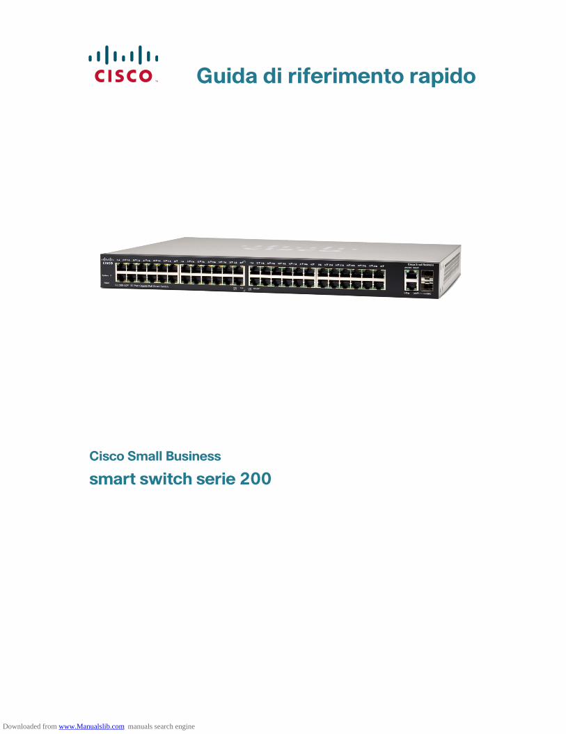
Guida di riferimento rapido
Cisco Small Business
smart switch serie 200
Downloaded from www.Manualslib.com manuals search engine
24 smart switch serie 200
Benvenuti
Grazie per aver scelto lo smart switch Cisco serie 200, un dispositivo di comunicazioni di rete di Cisco Small Business. Questo dispositivo è concepito per essere operativo out-of-the-box come ponte standard. Nella configurazione predefinita, dopo l'accensione, lo switch reindirizza i pacchetti tra i dispositivi di connessione.
Contenuto della confezione
• Cisco SF 200-24, SF 200-24P, SF 200-48, SF 200-48P, SG 200-18, SG 200-26, SG 200-26P, SG 200-50 o SG 200-50P Smart Switch
• Kit di montaggio in rack
• Cavo di alimentazione
• La presente guida di riferimento rapido
• CD del prodotto
Questa guida consente di familiarizzare con il layout dello smart switch e descrive come distribuire il dispositivo nella rete. Per ulteriori informazioni, visitare il sito www.cisco.com/smb.
Come montare lo switch di Cisco
È possibile montare lo switch in due modi:
• Disporre lo switch su una superficie piana.
• Montare lo switch in un rack standard (altezza di 1 unità rack).
Non montare il dispositivo in un luogo in cui sussiste una delle seguenti condizioni:
Temperatura ambiente alta. La temperatura ambiente non deve superare i 40 °C (104 °F).
Poca circolazione dell'aria. Per impedire il surriscaldamento, entrambi i pannelli laterali devono essere liberi.
Sovraccarico meccanico. Il dispositivo deve essere in piano, stabile e sicuro per evitare che scivoli o che si sposti.
Sovraccarico del circuito. Il collegamento del dispositivo alla presa di corrente non deve sovraccaricare il circuito elettrico.
1
Downloaded from www.Manualslib.com manuals search engine

smart switch serie 200 25
Installazione all'interno di rack
Se lo switch può essere montato in un rack, verrà fornito un apposito kit per il montaggio. Per montare lo switch in un qualsiasi rack standard, fissare in modo sicuro le staffe di montaggio ai lati dello switch utilizzando l'hardware fornito.
PRECAUZIONE Per garantire la stabilità, caricare il rack dal basso all'alto, con i dispositivi più pesanti sul basso. È probabile che un rack più pesante risulti instabile e che si possa rovesciare.
Come connettere dispositivi di rete
Connettere lo smart switch alla rete come descritto di seguito:
PASSAGGIO1 Connettere il cavo Ethernet alla porta Ethernet di un computer, di una stampante, di un sistema di memorizzazione di rete o di un altro dispositivo di rete.
PASSAGGIO2 Collegare l'altra estremità del cavo Ethernet a una delle porte Ethernet numerate dello smart switch.
Il LED della porta si illumina se il dispositivo connesso è attivo. Per maggiori informazioni sulle differenti porte e LED di ogni switch, fare riferimento a Funzionalità dello smart switch di Cisco Small Business, pagina 29.
PASSAGGIO3 Ripetere il Passaggio 1 e il Passaggio 2 per ogni dispositivo che si desidera connettere allo smart switch.
NOTA Cisco raccomanda l'utilizzo di Cat5 o di un cavo migliore per la connessione Gigabit. Quando si collegano i dispositivi di rete, non superare la lunghezza massima dei cavi pari a 100 metri (328 piedi). Prima che i dispositivi o la rete LAN collegati siano operativi dopo la connessione potrebbe trascorrere anche un minuto. Questo è normale.
Considerazioni su Power over Ethernet
Se lo switch è uno dei modelli Power over Ethernet (PoE), tenere in considerazione il seguente requisito di alimentazione:
2
Downloaded from www.Manualslib.com manuals search engine

26 smart switch serie 200
• In quanto dispositivo PSE (Power Sourcing Equipment), lo switch può fornire fino a 15,4 watt per porta PoE a un dispositivo alimentato (PD, Powered Device).
PoE è disponibile sulle seguenti porte:
Utilizzare la seguente tabella per determinare la quantità di alimentazione disponibile per tutti i dispositivi sullo switch.
Come configurare lo smart switch di Cisco Small Business
Operazioni preliminari
Verificare che sia disponibile un computer con Microsoft Internet Explorer (versione 6 o successiva) o Firefox (versione 2.0 o successiva).
Come accedere allo switch e gestirlo con l'interfaccia basata sul Web
Per accedere allo switch tramite un'interfaccia basata sul Web è necessario conoscere l'indirizzo IP di gestione dello switch. Nella configurazione predefinita dello switch viene utilizzato l'indirizzo IP con i valori predefiniti di 192.168.1.254 finché non si ottiene un indirizzo IP da un server DHCP o viene cambiato in un indirizzo IP statico.
Quando lo switch utilizza l'indirizzo IP con valori predefiniti, il LED di sistema continua a lampeggiare. Quando lo switch utilizza un indirizzo IP assegnato da un server DHCP o un indirizzo IP statico configurato dall'amministratore, il LED di sistema rimane acceso.
NOTA Se l'indirizzo IP dello smart switch viene modificato da un server DHCP o manualmente, l'accesso allo smart switch verrà perso e sarà necessario inserire il nuovo indirizzo IP per poter configurare il dispositivo.
Modello Porte
SF 200-24P e SG 200-26P 1-6 e 13-18
SF 200-24P e SG 200-26P 1-12 e 25-36
Modello Alimentazione dedicata a PoE
SF 200-24P 100 watt
SF 200-48P 180 watt
SG 200-26P 100 watt
SG 200-50P 180 watt
3
Downloaded from www.Manualslib.com manuals search engine

smart switch serie 200 27
Per configurare lo smart switch:
PASSAGGIO1 Accendere il computer e lo switch.
PASSAGGIO2 Collegare il computer allo switch. È possibile collegare lo switch alla stessa subnet IP tramite una connessione diretta con un cavo Ethernet o connettendoli alla stessa rete LAN dello switch tramite altri switch. È inoltre possibile collegare il computer allo switch da un'altra subnet IP tramite uno più router IP.
PASSAGGIO3 Impostare la configurazione IP sul computer.
a. Se lo switch utilizza l'indirizzo IP statico predefinito 192.168.1.254, è necessario scegliere un indirizzo IP nell'intervallo 192.168.1.1-192.168.1.253 che non sia già utilizzato da un altro dispositivo.
b. Se gli indirizzi IP verranno assegnati da DHCP, assicurarsi che il server DHCP sia in esecuzione e che possa essere raggiunto dallo switch e dal computer. Può essere necessario disconnettere e riconnettere i dispositivi per far sì che scoprano i loro nuovi indirizzi IP dal server DHCP.
NOTA I dettagli su come modificare l'indirizzo IP sul computer dipendono dal tipo di architettura e dal sistema operativo utilizzati. Consultare la funzionalità’ Guida e supporto del computer e cercare “Indirizzamento IP”.
PASSAGGIO4 Verrà visualizzata una finestra del browser. Se viene chiesto di installare un plug-in Active-X durante la connessione al dispositivo, seguire le istruzioni e installare il plug-in.
PASSAGGIO5 Inserire l'indirizzo IP dello switch nella barra degli indirizzi e premere Invio. Ad esempio, http://192.168.1.254.
Verrà visualizzata la pagina di accesso dello smart switch.
PASSAGGIO6 Inserire le informazioni di accesso:
Il nome utente è cisco
La password predefinita è cisco (le password fanno distinzione tra maiuscole e minuscole)
PASSAGGIO7 Se si tratta del primo accesso con il nome utente e la password predefiniti, verrà visualizzata la pagina Modifica password. Immettere una nuova password amministratore e fare clic su Applica.
Downloaded from www.Manualslib.com manuals search engine

28 smart switch serie 200
PRECAUZIONE Assicurarsi che le modifiche apportate alla configurazione vengano salvate prima di uscire dall'interfaccia basata sul Web facendo clic sull'icona Salva e, successivamente, su Avanti. Se si esce prima di salvare la configurazione tutte le modifiche andranno perse.
Verrà visualizzata la schermata Introduzione. È ora possibile configurare lo switch. Per ulteriori informazioni fare riferimento alla Guida all'amministrazione degli smart switch di Cisco Small Business.
Risoluzione dei problemi relativi alla connessione
Se non è possibile accedere allo switch dall'interfaccia basata sul Web, lo switch potrebbe non essere raggiungibile dal computer. È possibile verificare le connessioni di rete utilizzando il comando ping. La sezione seguente mostra come utilizzare il comando “ping” in un ambiente Windows:
PASSAGGIO1 Selezionare Start > Esegui per aprire una finestra di comando, quindi digitare cmd.
PASSAGGIO2 Nel prompt dei comandi, digitare ping, quindi inserire l'indirizzo IP dello smart switch. Ad esempio ping 192.168.1.254 (l'indirizzo IP statico predefinito dello smart switch).
Se lo switch viene raggiunto dovrebbe apparire un messaggio simile a quello seguente:
Pinging 192.168.1.254 with 32 bytes of data:Reply from 192.168.1.254: bytes=32 time<1ms TTL=128
Se lo switch non viene raggiunto dovrebbe apparire un messaggio simile a quello seguente:
Pinging 192.168.1.254 with 32 bytes of data:Request timed out.
Possibili cause e risoluzioni
Mancanza di alimentazione:
Accendere lo switch e il computer se sono spenti.
Downloaded from www.Manualslib.com manuals search engine

smart switch serie 200 29
Connessione Ethernet danneggiata:
Verificare i LED per indicazioni corrette. Verificare i connettori del cavo Ethernet per assicurarsi che siano inseriti correttamente nello switch e nel computer.
Indirizzo IP sbagliato o in conflitto:
Assicurarsi che l'indirizzo IP dello switch utilizzato sia corretto. Verificare con l'amministratore di rete l'attuale indirizzo IP dello switch. Il LED di sistema offre un'indicazione visiva del punto in cui lo switch ha ricevuto l'indirizzo IP; per i dettagli, vedere la sezione 4.
Assicurarsi che nessun altro dispositivo stia utilizzando lo stesso indirizzo IP dello switch.
Nessun percorso IP:
Se lo switch e il computer hanno subnet IP differenti, è necessario che uno o più router instradi i pacchetti tra le due subnet.
Tempo di accesso insolitamente lungo:
Sulla base della logica di rilevamento del loop STP, se si aggiungono nuove connessioni potrebbero essere necessari dai 30 ai 60 secondi prima che le interfacce e/o la rete LAN interessate inizino a funzionare.
Funzionalità dello smart switch di Cisco Small Business
In questa sezione viene descritta la parte esterna degli smart switch incluse le porte, i LED e le connessioni. Non tutti i modelli avranno tutte le caratteristiche descritte.
Porte
Porte Ethernet RJ-45. Utilizzare queste porte per collegare i dispositivi di rete quali computer, stampanti e punti di accesso allo switch.
Mini-GBIC (se presenti). Alle porte di conversione dell'interfaccia Gigabit è possibile collegare moduli di espansione mini-GBIC per consentire di collegare lo smart switch ad altri switch mediante fibra ottica.
• Le mini porte di conversione dell'interfaccia Gigabit sono compatibili con i moduli Cisco mini-GBIC MGBSX1, MGBLH1, MGBLX1, MGBBX1, MFELX1, MFEFX1 e MFEBX1 oltre ad ulteriori marchi di moduli mini-GBIC.
4
Downloaded from www.Manualslib.com manuals search engine

30 smart switch serie 200
• L'interfaccia mini-GBIC è una porta di combinazione condivisa con un'altra interfaccia RJ-45. Quando la porta mini-GBIC è attiva, la porta RJ-45 adiacente è disattivata.
• I LED della porta RJ-45 corrispondente lampeggiano di colore verde per rispondere al traffico dell'interfaccia mini-GBIC.
LED
LED del sistema (verde). Si illumina quando lo switch è acceso e lampeggia durante il riavvio, l'esecuzione di autotest e l'acquisizione di un indirizzo IP. Se il LED è di color ambra e lampeggia significa che lo switch ha rilevato un errore dell'hardware.
LED di collegamento/attività (verde). Posizionato sulla sinistra della porta. Si illumina quando viene rilevato un collegamento tra la porta corrispondente e un altro dispositivo. Lampeggia quando la porta sta facendo passare il traffico.
NOTA Il sistema e i LED di collegamento/attività si trovano su tutti i modelli dello switch. I seguenti LED si trovano solo sui modelli di switch che presentano queste funzionalità:
PoE (se presente) (ambra). Posizionato sulla destra della porta. Si illumina per indicare che l'alimentazione viene fornita a un dispositivo associato alla porta corrispondente.
LED 100M (se presente) (verde). Posizionato sulla destra della porta. Si illumina quando un altro dispositivo è connesso alla porta, quando è acceso e quando viene stabilito un collegamento a 100 Mbps tra i dispositivi. Il LED spento indica che la velocità di connessione è inferiore ai 100 Mbps o che niente è collegato alla porta.
LED Gigabit (se presente) (verde). Posizionato sulla destra della porta. Si illumina quando un altro dispositivo è connesso alla porta, quando è acceso e quando viene stabilito un collegamento a 1000 Mbps tra i dispositivi. Il LED spento indica che la velocità di connessione è inferiore ai 1000 Mbps o che niente è collegato alla porta.
Mini-GBIC (se presente) (verde). Posizionato sulla destra della porta. Si illumina quando viene effettuata una connessione tramite la porta RJ-45 condivisa. Lampeggia quando la porta sta facendo passare il traffico.
Funzionalità aggiuntive
Lo switch può anche presentare un pulsante di reimpostazione. Lo switch può essere reimpostato inserendo uno spillo o una graffetta nell'apertura di reimpostazione. Vedere “Come ripristinare le impostazioni predefinite del dispositivo” per maggiori dettagli.
Downloaded from www.Manualslib.com manuals search engine
smart switch serie 200 31
Pannello posteriore
La porta di alimentazione è posizionata sul pannello posteriore dello smart switch.
Come ripristinare le impostazioni predefinite del dispositivo
Per utilizzare il pulsante Ripristina per riavviare o reimpostare lo smart switch, eseguire le seguenti operazioni:
• Per riavviare lo smart switch, premere il pulsante Ripristina per meno di 10 secondi.
• Per ripristinare le impostazioni predefinite dello smart switch:
1. Disconnettere lo smart switch dalla rete o disattivare tutti i server DHCP presenti nella rete.
2. Una volta acceso, tenere premuto il pulsante Ripristina per più di 10 secondi.
5
Downloaded from www.Manualslib.com manuals search engine
32 smart switch serie 200
Risorse aggiuntive
Supporto
Cisco Small Business Support Community
www.cisco.com/go/smallbizsupport
Cisco Small Business Support and Resources
www.cisco.com/go/smallbizhelp
Contatti del supporto telefonico www.cisco.com/en/US/support/tsd_cisco_ small_business_support_center_contacts.html
Cisco Small Business Firmware Downloads
www.cisco.com/go/smallbizfirmware
Selezionare un collegamento per scaricare il firmware relativo ai prodotti Cisco Small Business. Non sono necessari dati di accesso.
I download per tutti gli altri prodotti Cisco Small Business, inclusi i sistemi di memorizzazione di rete, sono disponibili nell'area Download su Cisco.com al sito www.cisco.com/go/software (richiede la registrazione/immissione di dati di accesso).
Documentazione prodotti
Smart Switch di Cisco Small Business
www.cisco.com/go/smallbizsmartswitches
Guida di riferimento rapido agli smart switch serie 200
www.cisco.com/en/US/docs/switches/lan/csbss/sf20x_sg20x/quick_start/78-19501-01.pdf
Guida all'amministrazione degli smart switch serie 200
www.cisco.com/en/US/docs/switches/lan/csbss/sf20x_sg20x/administration_guide/OL-22849-01.pdf
Conformità alle normative e informazioni sulla sicurezza
www.cisco.com/en/US/docs/switches/lan/csbms/sfe2000/release/notes/Class_A_Switches_RCSI.pdf
Informazioni sulla garanzia www.cisco.com/go/warranty
Cisco Small Business
Cisco Partner Central per Small Business (richiede l'immissione di dati di accesso da parte dei partner)
www.cisco.com/web/partners/sell/smb
Cisco Small Business Home www.cisco.com/smb
6
Downloaded from www.Manualslib.com manuals search engine
Sede centrale in AmericaCisco Systems, Inc.170 West Tasman DriveSan Jose, CA 95134-1706USAhttp://www.cisco.comSupporto per i prodotti Small Business negli Stati Uniti: 1-866-606-1866 (numero verde, 24 ore su 24/ 7 giorni su 7)Numeri di contatto globali del supporto per i prodotti Small
Cisco, Cisco Systems, il logo Cisco e il logo Cisco Systems sono marchi o marchi registrati diCisco e/o di società affiliate negli Stati Uniti e in altri paesi. Tutti gli altri marchi citati nel
presente documento o sito Web appartengono ai rispettivi proprietari. L'uso del termine
partner non implica una relazione di partnership tra Cisco e altre società. (1002R)
© 2010 Cisco Systems, Inc. Tutti i diritti riservati.
Downloaded from www.Manualslib.com manuals search engine

Kurzanleitung
Cisco Small Business
Serie 200 Smart Switches
Downloaded from www.Manualslib.com manuals search engine
Serie 200 Smart Switches 35
Willkommen
Vielen Dank, dass Sie sich für den Cisco Serie 200 Smart Switch, ein Netzwerkkommunikationsgerät von Cisco Small Business, entschieden haben. Dieses Gerät ist vorkonfiguriert und sofort als Standard-Bridge einsatzbereit. In der Standardkonfiguration überträgt das Gerät nach dem Einschalten Pakete zwischen den angeschlossenen Geräten.
Lieferumfang
• Cisco SF 200-24, SF 200-24P, SF 200-48, SF 200-48P, SG 200-18, SG 200-26, SG 200-26P, SG 200-50 oder SG 200-50P Smart Switch.
• Rackinstallations-Kit
• Netzkabel
• diese Kurzanleitung
• Produkt-CD
In dieser Anleitung wird der Aufbau des Smart Switch beschrieben und wie das Gerät im Netzwerk bereitgestellt wird. Weitere Informationen finden Sie unter www.cisco.com/smb.
Aufstellen und Montage des Cisco Switch
Der Switch kann auf zweierlei Weise aufgestellt bzw. montiert werden:
• Aufstellen des Switch auf einer flachen Oberfläche
• Montage des Switch in einem Standard-Rack (1 Einheit hoch)
Stellen Sie das Gerät nicht an einem Ort auf, an dem eine der folgenden Bedingungen vorherrscht:
Hohe Umgebungstemperatur – Die Umgebungstemperatur darf 40 C° nicht überschreiten.
Verringerte Luftzirkulation – Auf beiden Seiten des Gerätes muss freier Raum bleiben, damit eine Überhitzung vermieden wird.
Mechanische Überlastung – Das Gerät muss eben, stabil und sicher aufgestellt werden, damit es nicht verrutscht oder sich bewegt.
Überlastung des Stromkreises – Das Anschließen des Geräts an die Steckdose darf diesen Stromkreis nicht überlasten.
1
Downloaded from www.Manualslib.com manuals search engine

36 Serie 200 Smart Switches
Rackinstallation
Wenn der Switch in einem Rack installiert werden kann, wird er mit einem Rackinstallations-Kit geliefert. Um den Switch in einem Standardrack zu installieren, befestigen Sie die Rack-Montageklammern mit dem beiliegenden Befestigungsmaterial an den Seiten des Switch und ziehen Sie die Klammern fest an.
Achtung Um die Stabilität des Racks zu gewährleisten, sollten Sie dieses von unten beginnend mit Geräten bestücken und die schwersten Geräte unten im Rack platzieren. Ein Rack, dessen Schwerpunkt zu hoch liegt, kann instabil werden und umkippen.
Anschließen von Netzwerkgeräten
So verbinden Sie den Smart Switch mit dem Netzwerk:
Schritt 1 Verbinden Sie das Ethernet-Kabel mit dem Ethernet-Port eines Computers, Druckers, Netzwerkspeichers oder eines anderen Netzwerkgeräts.
Schritt 2 Verbinden Sie das andere Ende des Ethernet-Kabels mit einem der durchnummerierten Ethernet-Ports des Smart Switch.
Die LED des Ports leuchtet auf, wenn das angeschlossene Gerät aktiv ist. Informationen zu den unterschiedlichen Ports und LEDs an den verschiedenen Switches finden Sie unter Funktionen des Cisco Small Business Smart Switch, Seite 40.
Schritt 3 Wiederholen Sie Schritt 1 und Schritt 2 für jedes Gerät, das Sie mit dem Smart Switch verbinden möchten.
Hinweis Cisco empfiehlt für Gigabit-Verbindungen die Verwendung eines Kabels der Kategorie 5 oder höher. Beachten Sie beim Anschließen Ihrer Netzwerkgeräte, dass die maximale Kabellänge von 100 Metern nicht überschritten wird. Nach dem Herstellen der Verbindung kann es bis zu eine Minute dauern, bis das neu angeschlossene Gerät oder das LAN betriebsbereit ist. Diese Verzögerung ist normal.
2
Downloaded from www.Manualslib.com manuals search engine
Serie 200 Smart Switches 37
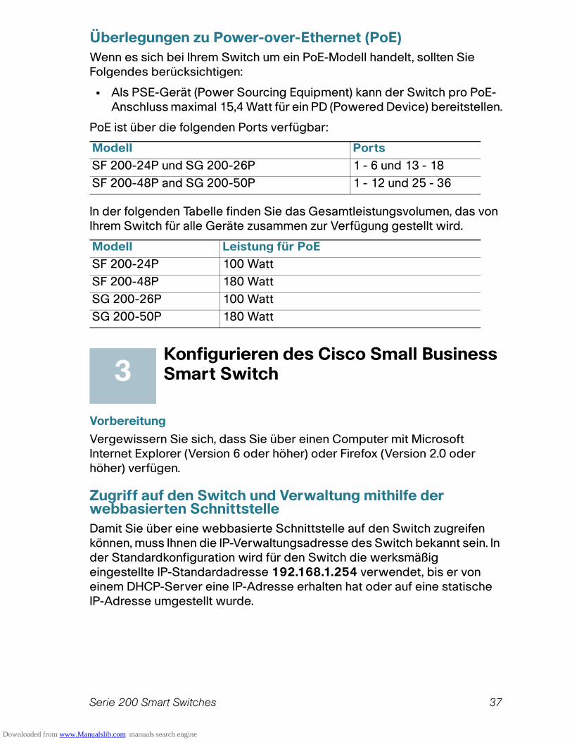
Überlegungen zu Power-over-Ethernet (PoE)
Wenn es sich bei Ihrem Switch um ein PoE-Modell handelt, sollten Sie Folgendes berücksichtigen:
• Als PSE-Gerät (Power Sourcing Equipment) kann der Switch pro PoE-Anschluss maximal 15,4 Watt für ein PD (Powered Device) bereitstellen.
PoE ist über die folgenden Ports verfügbar:
In der folgenden Tabelle finden Sie das Gesamtleistungsvolumen, das von Ihrem Switch für alle Geräte zusammen zur Verfügung gestellt wird.
Konfigurieren des Cisco Small Business Smart Switch
Vorbereitung
Vergewissern Sie sich, dass Sie über einen Computer mit Microsoft Internet Explorer (Version 6 oder höher) oder Firefox (Version 2.0 oder höher) verfügen.
Zugriff auf den Switch und Verwaltung mithilfe der webbasierten Schnittstelle
Damit Sie über eine webbasierte Schnittstelle auf den Switch zugreifen können, muss Ihnen die IP-Verwaltungsadresse des Switch bekannt sein. In der Standardkonfiguration wird für den Switch die werksmäßig eingestellte IP-Standardadresse 192.168.1.254 verwendet, bis er von einem DHCP-Server eine IP-Adresse erhalten hat oder auf eine statische IP-Adresse umgestellt wurde.
Modell Ports
SF 200-24P und SG 200-26P 1 - 6 und 13 - 18
SF 200-48P and SG 200-50P 1 - 12 und 25 - 36
Modell Leistung für PoE
SF 200-24P 100 Watt
SF 200-48P 180 Watt
SG 200-26P 100 Watt
SG 200-50P 180 Watt
3
Downloaded from www.Manualslib.com manuals search engine

38 Serie 200 Smart Switches
Wenn die werksmäßig konfigurierte IP-Standardadresse für den Switch verwendet wird, blinkt dessen System-LED ununterbrochen. Wird für den Switch eine vom DHCP-Server zugewiesene IP-Adresse oder eine vom Administrator konfigurierte statische IP-Adresse verwendet, leuchtet die System-LED ständig.
Hinweis Wird die IP-Adresse des Smart Switch entweder von einem DHCP-Server oder manuell geändert, geht der Zugriff auf den Smart Switch verloren. In diesem Fall müssen Sie die neue IP-Adresse verwenden, um das Gerät zu konfigurieren.
So konfigurieren Sie den Smart Switch:
Schritt 1 Schalten Sie den Computer und den Switch ein.
Schritt 2 Schließen Sie den Computer an den Switch an. Sie können mittels Ethernet-Kabel eine direkte Verbindung zu demselben IP-Subnetz herstellen, in dem sich der Switch befindet, oder Sie können eine Verbindung zu dem LAN, in dem sich der Switch befindet, über andere Switches einrichten. Sie können Ihren Computer auch aus einem anderen IP-Subnetz über einen oder mehrere IP-Router mit dem Switch verbinden.
Schritt 3 Führen Sie die IP-Konfigurierung auf Ihrem Computer durch.
a. Wenn vom Switch die statische IP-Standardadresse 192.168.1.254 verwendet wird, müssen Sie eine IP-Adresse im Bereich 192.168.1.2 - 192.168.1.253 wählen, die noch nicht für ein anderes Gerät verwendet wird.
b. Erfolgt die Zuweisung der IP-Adressen durch einen DHCP-Server, vergewissern Sie sich, dass dieser ausgeführt wird und vom Switch und vom Computer erreicht werden kann. Möglicherweise ist es erforderlich, die Verbindung der Geräte zu trennen und anschließend wieder herzustellen, damit die durch den DHCP-Server zugewiesenen neuen IP-Adressen erkannt werden.
Hinweis Die genaue Vorgehensweise beim Ändern der IP-Adresse auf Ihrem Computer hängt von der jeweiligen Architektur und dem verwendeten Betriebssystem ab. Um Informationen hierzu zu erhalten, rufen Sie die Hilfe- und Support-Funktionen Ihres Computers auf und suchen Sie nach dem Stichwort „IP-Adressierung“.
Schritt 4 Öffnen Sie ein Webbrowser-Fenster. Wenn Sie zur Installation eines Active-X-Plug-Ins aufgefordert werden, nachdem Sie das Gerät angeschlossen haben, führen Sie die Plug-In-Installation durch.
Downloaded from www.Manualslib.com manuals search engine

Serie 200 Smart Switches 39
Schritt 5 Geben Sie die IP-Adresse des Switch in die Adresszeile ein, und drücken Sie die Eingabetaste. Zum Beispiel http://192.168.1.254.
Die Smart Switch-Anmeldeseite wird angezeigt.
SCHRITT6 Geben Sie die Anmeldeinformationen ein:
Der Benutzername lautet cisco
Das Standardkennwort lautet cisco (bei Kennwörtern wird zwischen Groß- und Kleinschreibung unterschieden)
Schritt 7 Wenn Sie sich zum ersten Mal mit dem Standardbenutzernamen und -kennwort anmelden, wird die Seite Kennwort ändern angezeigt. Geben Sie ein neues Administratorkennwort ein, und klicken Sie auf Übernehmen.
Achtung Achten Sie darauf, alle Konfigurationsänderungen zu speichern, bevor Sie die webbasierte Schnittstelle schließen. Klicken Sie zu diesem Zweck auf das Symbol Speichern, dann auf Übernehmen. Wenn Sie die webbasierte Schnittstelle schließen, ohne die Konfiguration zu speichern, gehen alle Änderungen verloren.
Das Fenster Erste Schritte wird angezeigt. Sie können den Switch jetzt konfigurieren. Weitere Informationen finden Sie im Administratorhandbuch für den Cisco Small Business Smart Switch.
Fehlerbehebung bei der Verbindung
Wenn Sie über die webbasierte Schnittstelle nicht auf den Switch zugreifen können, ist der Switch für den Computer möglicherweise nicht erreichbar. Sie können Netzwerkverbindungen mit dem Ping-Befehl überprüfen. Im folgenden Abschnitt ist dargestellt, wie der „Ping“-Befehl in einer Windows-Umgebung verwendet wird:
Schritt 1 Wählen Sie Start > Ausführen, um ein Befehlsfenster zu öffnen, und geben Sie cmd ein.
Schritt 2 Geben Sie in das Befehlsfenster den Befehl ping und die IP-Adresse des Smart Switch ein. Zum Beispiel ping 192.168.1.254 (die IP-Standardadresse des Smart Switch).
Wenn Sie den Switch erreichen können, erhalten Sie eine Antwort, die der Folgenden ähnlich ist:
Pinging 192.168.1.254 with 32 bytes of data:Reply from 192.168.1.254: bytes=32 time<1ms TTL=128
Downloaded from www.Manualslib.com manuals search engine
40 Serie 200 Smart Switches
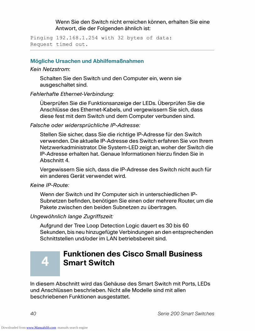
Wenn Sie den Switch nicht erreichen können, erhalten Sie eine Antwort, die der Folgenden ähnlich ist:
Pinging 192.168.1.254 with 32 bytes of data:Request timed out.
Mögliche Ursachen und Abhilfemaßnahmen
Kein Netzstrom:
Schalten Sie den Switch und den Computer ein, wenn sie ausgeschaltet sind.
Fehlerhafte Ethernet-Verbindung:
Überprüfen Sie die Funktionsanzeige der LEDs. Überprüfen Sie die Anschlüsse des Ethernet-Kabels, und vergewissern Sie sich, dass diese fest mit dem Switch und dem Computer verbunden sind.
Falsche oder widersprüchliche IP-Adresse:
Stellen Sie sicher, dass Sie die richtige IP-Adresse für den Switch verwenden. Die aktuelle IP-Adresse des Switch erfahren Sie von Ihrem Netzwerkadministrator. Die System-LED zeigt an, woher der Switch die IP-Adresse erhalten hat. Genaue Informationen hierzu finden Sie in Abschnitt 4.
Vergewissern Sie sich, dass die IP-Adresse des Switch nicht auch für ein anderes Gerät verwendet wird.
Keine IP-Route:
Wenn der Switch und Ihr Computer sich in unterschiedlichen IP-Subnetzen befinden, benötigen Sie einen oder mehrere Router, um die Pakete zwischen den beiden Subnetzen zu übertragen.
Ungewöhnlich lange Zugriffszeit:
Aufgrund der Tree Loop Detection Logic dauert es 30 bis 60 Sekunden, bis neu hinzugefügte Verbindungen an den entsprechenden Schnittstellen und/oder im LAN betriebsbereit sind.
Funktionen des Cisco Small Business Smart Switch
In diesem Abschnitt wird das Gehäuse des Smart Switch mit Ports, LEDs und Anschlüssen beschrieben. Nicht alle Modelle sind mit allen beschriebenen Funktionen ausgestattet.
4
Downloaded from www.Manualslib.com manuals search engine

Serie 200 Smart Switches 41
Ports
RJ-45-Ethernet-Ports – Über diese Ports können Sie Netzwerkgeräte wie Computer, Drucker und Access Points an den Switch anschließen.
MiniGBIC (sofern vorhanden) – Die MiniGBIC-Ports (GBIC, Gigabit Interface Converter) sind Anschlusspunkte für MiniGBIC-Module, sodass zwischen dem Smart Switch und anderen Switches eine Uplink-Verbindung über einen Lichtwellenleiter hergestellt werden kann.
• MiniGBIC-Ports sind kompatibel mit den MiniGBIC-Modulen MGBSX1, MGBLH1, MGBLX1, MGBBX1, MFELX1, MFEFX1 und MFEBX1 von Cisco sowie mit MiniGBIC-Modulen anderer Hersteller.
• Die MiniGBIC-Schnittstelle ist ein Mehrfach-Port, der mit einer anderen RJ-45-Schnittstelle geteilt wird. Wenn der MiniGBIC aktiv ist, ist der benachbarte RJ-45-Port deaktiviert.
• Als Reaktion auf Datenverkehr an der miniGBIC-Schnittstelle blinken die LEDs des entsprechenden RJ-45-Ports grün.
LEDs
System-LED – (Grün) Leuchtet ständig, wenn der Switch eingeschaltet ist. Sie blinkt während des Boot-Vorgangs, beim Durchführen von Selbsttests und beim Erhalt einer IP-Adresse. Wenn die LED bernsteinfarben blinkt, wurde durch den Switch ein Hardwarefehler festgestellt.
LINK/ACT-LED – (Grün) Befindet sich auf der linken Seite des Ports. Sie leuchtet ständig, wenn eine Verbindung zwischen dem entsprechenden Port und einem anderen Gerät erkannt wird. Sie blinkt, wenn der Port Daten weiterleitet.
Hinweis Die System-LED und die LINK/ACT-LED sind bei allen Switch-Modellen vorhanden. Die folgenden LEDs sind nur bei Switch-Modellen mit den entsprechenden Funktionen vorhanden:
PoE (sofern vorhanden) – (Bernsteinfarben) Auf der rechten Seite des Ports. Diese LED leuchtet kontinuierlich, wenn das Gerät, das an den entsprechenden Port angeschlossen ist, mit Spannung versorgt wird.
100M LED (sofern vorhanden) – (Grün) Auf der rechten Seite des Ports. Diese LED leuchtet kontinuierlich, wenn ein anderes Gerät an den Port angeschlossen und eingeschaltet ist und eine 100 Mbps-Verbindung zwischen den Geräten besteht. Wenn die LED nicht leuchtet, liegt die Verbindungsgeschwindigkeit unter 100 MBit/s, oder an den Port ist kein Gerät angeschlossen.
Gigabit LED (sofern vorhanden) – (Grün) Auf der rechten Seite des Ports. Diese LED leuchtet kontinuierlich, wenn ein anderes Gerät an den Port angeschlossen und eingeschaltet ist und eine 1000 Mbps-Verbindung
Downloaded from www.Manualslib.com manuals search engine

42 Serie 200 Smart Switches
zwischen den Geräten besteht. Wenn die LED nicht leuchtet, liegt die Verbindungsgeschwindigkeit unter 1000 MBit/s, oder an den Port ist kein Gerät angeschlossen.
MiniGBIC (sofern vorhanden) – (Grün) Auf der rechten Seite des Ports. Diese LED leuchtet kontinuierlich, wenn eine Verbindung über den gemeinsam verwendeten RJ-45-Port erfolgt. Sie blinkt, wenn der Port Daten weiterleitet.
Weitere Funktionen
Der Switch ist u. U. auch mit einer Reset-Taste ausgestattet. Der Switch kann zurückgesetzt werden, indem eine Nadel oder eine Büroklammer in die Reset-Öffnung eingeführt wird. Weitere Informationen finden Sie unter “Wiederherstellen der werkseitigen Standardeinstellungen des Geräts”.
Rückseite
Der Netzanschluss befindet sich auf der Rückseite des Smart Switch.
Wiederherstellen der werkseitigen Standardeinstellungen des Geräts
Gehen Sie folgendermaßen vor, um mit der Reset-Taste einen Neustart durchzuführen oder den Smart Switch auf die Werkseinstellungen zurückzusetzen:
• Um einen Neustart des Smart Switch durchzuführen, drücken Sie die Taste Reset für weniger als 10 Sekunden.
• So stellen Sie die werkseitigen Standardeinstellungen des Smart Switch wieder her:
1. Trennen Sie den Smart Switch vom Netzwerk, oder deaktivieren Sie alle DHCP-Server in Ihrem Netzwerk.
2. Halten Sie die Taste Reset bei eingeschaltetem Gerät länger als 10 Sekunden gedrückt.
5
Downloaded from www.Manualslib.com manuals search engine
Serie 200 Smart Switches 43
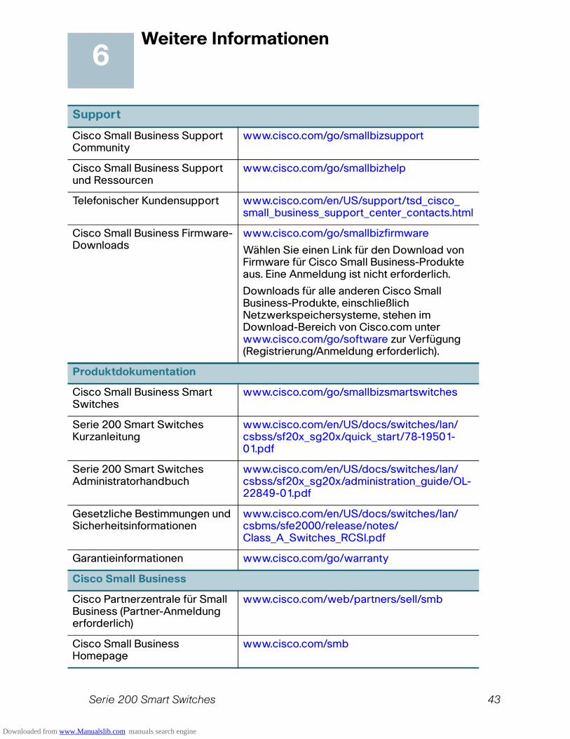
Weitere Informationen
Support
Cisco Small Business Support Community
www.cisco.com/go/smallbizsupport
Cisco Small Business Support und Ressourcen
www.cisco.com/go/smallbizhelp
Telefonischer Kundensupport www.cisco.com/en/US/support/tsd_cisco_ small_business_support_center_contacts.html
Cisco Small Business Firmware-Downloads
www.cisco.com/go/smallbizfirmware
Wählen Sie einen Link für den Download von Firmware für Cisco Small Business-Produkte aus. Eine Anmeldung ist nicht erforderlich.
Downloads für alle anderen Cisco Small Business-Produkte, einschließlich Netzwerkspeichersysteme, stehen im Download-Bereich von Cisco.com unter www.cisco.com/go/software zur Verfügung (Registrierung/Anmeldung erforderlich).
Produktdokumentation
Cisco Small Business Smart Switches
www.cisco.com/go/smallbizsmartswitches
Serie 200 Smart Switches Kurzanleitung
www.cisco.com/en/US/docs/switches/lan/csbss/sf20x_sg20x/quick_start/78-19501-01.pdf
Serie 200 Smart Switches Administratorhandbuch
www.cisco.com/en/US/docs/switches/lan/csbss/sf20x_sg20x/administration_guide/OL-22849-01.pdf
Gesetzliche Bestimmungen und Sicherheitsinformationen
www.cisco.com/en/US/docs/switches/lan/csbms/sfe2000/release/notes/Class_A_Switches_RCSI.pdf
Garantieinformationen www.cisco.com/go/warranty
Cisco Small Business
Cisco Partnerzentrale für Small Business (Partner-Anmeldung erforderlich)
www.cisco.com/web/partners/sell/smb
Cisco Small Business Homepage
www.cisco.com/smb
6
Downloaded from www.Manualslib.com manuals search engine

Hauptsitz für Nord- und SüdamerikaCisco Systems, Inc.170 West Tasman DriveSan Jose, CA 95134-1706USAhttp://www.cisco.comSmall Business Support USA: +1 866 606 1866 (gebührenfrei, an allen Wochentagen rund um die Uhr)Kontakttelefonnummern für internationalen Small Business Support
Cisco, Cisco Systems, das Cisco-Logo und das Cisco Systems-Logo sind eingetragene
Marken oder Marken von Cisco und/oder seinen Tochtergesellschaften in den U SA undbestimmten anderen Ländern. Alle anderen in diesem Dokument oder auf dieser Website
genannten Marken sind Eigentum ihrer jeweiligen Inhaber. Die Verwendung des Worts
„Partner“ impliziert keine Partnerschaft zwischen Cisco und einem anderen Unternehmen.(1002R)
© 2010 Cisco Systems, Inc. Alle Rechte vorbehalten.
Downloaded from www.Manualslib.com manuals search engine

Guide de démarrage rapide
Cisco Small Business
Commutateurs intelligents série 200
Downloaded from www.Manualslib.com manuals search engine
46 Commutateurs intelligents série 200
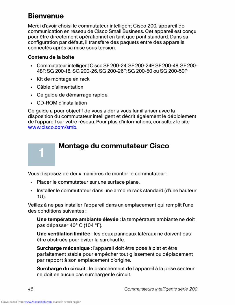
Bienvenue
Merci d’avoir choisi le commutateur intelligent Cisco 200, appareil de communication en réseau de Cisco Small Business. Cet appareil est conçu pour être directement opérationnel en tant que pont standard. Dans sa configuration par défaut, il transfère des paquets entre des appareils connectés après sa mise sous tension.
Contenu de la boîte
• Commutateur intelligent Cisco SF 200-24, SF 200-24P, SF 200-48, SF 200-48P, SG 200-18, SG 200-26, SG 200-26P, SG 200-50 ou SG 200-50P
• Kit de montage en rack
• Câble d’alimentation
• Ce guide de démarrage rapide
• CD-ROM d’installation
Ce guide a pour objectif de vous aider à vous familiariser avec la disposition du commutateur intelligent et décrit également le déploiement de l’appareil sur votre réseau. Pour plus d’informations, consultez le site www.cisco.com/smb.
Montage du commutateur Cisco
Vous disposez de deux manières de monter le commutateur :
• Placer le commutateur sur une surface plane.
• Installer le commutateur dans une armoire rack standard (d’une hauteur 1U).
Veillez à ne pas installer l’appareil dans un emplacement qui remplit l’une des conditions suivantes :
Une température ambiante élevée : la température ambiante ne doit pas dépasser 40° C (104 °F).
Une ventilation limitée : les deux panneaux latéraux ne doivent pas être obstrués pour éviter la surchauffe.
Surcharge mécanique : l’appareil doit être posé à plat et être parfaitement stable pour empêcher tout glissement ou déplacement par rapport à son emplacement d’origine.
Surcharge du circuit : le branchement de l’appareil à la prise secteur ne doit en aucun cas surcharger le circuit.
1
Downloaded from www.Manualslib.com manuals search engine
Commutateurs intelligents série 200 47
Montage en rack
Si votre commutateur peut être monté dans une armoire rack, il est livré avec un kit de montage en rack. Pour monter le commutateur en rack dans une armoire rack standard, fixez les supports de montage aux côtés du commutateur à l’aide du matériel fourni et veillez à bien les serrer.
ATTENTION ! Pour garantir une bonne stabilité, chargez l’armoire rack en partant du bas, où vous placerez les appareils les plus lourds. Si la charge est trop importante en haut de l’armoire rack, celle-ci risque de devenir instable et de basculer.
Connexion des appareils réseau
Pour connecter le commutateur intelligent au réseau :
ÉTAPE1 Branchez le câble Ethernet sur le port Ethernet d’un ordinateur, d’une imprimante, d’un périphérique de stockage réseau ou de tout autre appareil en réseau.
ÉTAPE2 Branchez l’autre extrémité du câble Ethernet à l’un des ports Ethernet numérotés du commutateur intelligent.
La LED du port s’allume lorsque l’appareil connecté est actif. Consultez la section Fonctionnalités du Commutateur intelligent Cisco Small Business, page 51, pour obtenir des informations détaillées sur les différents ports et LED de chaque commutateur.
ÉTAPE3 Renouvelez l’Étape 1 et l’Étape 2 pour chaque appareil que vous voulez relier au commutateur intelligent.
REMARQUE Cisco recommande d’utiliser un câble de catégorie 5 ou supérieure pour la connectivité Gigabit. Lorsque vous connectez vos appareils réseau, ne dépassez pas la distance de câblage maximale qui est de 100 mètres (328 pieds). Une fois la connexion établie, il est possible que les appareils reliés ou le réseau LAN ne soient opérationnels qu’au bout d’une minute. Ce comportement est normal.
Considérations relatives à l’alimentation électrique par câble Ethernet (PoE)
Si votre commutateur gère l’alimentation électrique par câble Ethernet (PoE), prenez en considération les éléments suivants :
2
Downloaded from www.Manualslib.com manuals search engine
48 Commutateurs intelligents série 200
• En tant qu’appareil PSE (Power Sourcing Equipment), le commutateur peut fournir un maximum de 15,4 watts par port PoE à un appareil alimenté (PD, Powered Device).
L'alimentation PoE est disponible sur les ports suivants :
Consultez le tableau suivant pour connaître la puissance totale disponible pour tous les appareils reliés à votre commutateur.
Configuration du Commutateur intelligent Cisco Small Business
Avant de commencer
Veillez à disposer d’un ordinateur doté de Microsoft Internet Explorer (version 6 ou ultérieure) ou de Firefox (version 2.0 ou ultérieure).
Accès et gestion de votre commutateur par l'interface Web
Afin d'accéder au commutateur depuis l'interface Web, vous devez connaître l'adresse IP de gestion du commutateur. Par défaut, ce dernier utilise l’adresse IP définie en usine (192.168.1.254) jusqu’à ce qu’il ait obtenu une adresse IP d’un serveur DHCP ou qu'il ait été configuré avec une adresse IP statique.
Lorsque le commutateur utilise l'adresse IP par défaut définie en usine, sa LED d'alimentation clignote de façon continue. Lorsque le commutateur utilise une adresse IP affectée par DHCP ou une adresse IP statique configurée par un administrateur, sa LED d'alimentation reste allumée.
REMARQUE En cas de modification de l’adresse IP du commutateur intelligent, que ce soit par un serveur DHCP ou manuellement, vous perdez votre accès au commutateur intelligent et devez entrer la nouvelle adresse IP pour pouvoir configurer l'appareil.
Modèle Ports
SF 200-24P et SG 200-26P 1 à 6 et 13 à 18
SF 200-48P et SG 200-50P 1 à 12 et 25 à 36
Modèle Puissance dédiée au PoE
SF 200-24P 100 watts
SF 200-48P 180 watts
SG 200-26P 100 watts
SG 200-50P 180 watts
3
Downloaded from www.Manualslib.com manuals search engine

Commutateurs intelligents série 200 49
Pour configurer le commutateur intelligent :
ÉTAPE1 Mettez l’ordinateur et le commutateur sous tension.
ÉTAPE2 Connectez l’ordinateur au commutateur. Vous pouvez le connecter au même sous-réseau IP que le commutateur en les reliant directement avec un câble Ethernet, ou en le connectant au même réseau LAN que celui sur lequel réside le commutateur, via d’autres commutateurs. Vous pouvez également connecter votre ordinateur au commutateur à partir d’un autre sous-réseau IP, via un ou plusieurs routeurs IP.
ÉTAPE3 Définissez la configuration IP sur votre ordinateur.
a. Si le commutateur utilise l’adresse IP statique par défaut 192.168.1.254, vous devez choisir une adresse IP qui n’est pas encore utilisée dans la plage 192.168.1.1—192.168.1.253.
b. Si les adresses IP sont affectées par DHCP, assurez-vous que votre serveur DHCP est en cours d’exécution et qu’il peut être atteint depuis le commutateur et l’ordinateur. Vous devrez peut-être déconnecter et reconnecter les appareils pour qu’ils puissent détecter leur nouvelle adresse IP fournie par le serveur DHCP.
REMARQUE La procédure spécifique à suivre pour modifier l’adresse IP sur votre ordinateur dépend du type d’architecture et du système d’exploitation dont vous disposez. Consultez l’aide et l’assistance en ligne de votre ordinateur et effectuez une recherche portant sur « Adressage IP ».
ÉTAPE4 Ouvrez une fenêtre dans un navigateur Web. Si vous êtes invité à installer un plug-in ActiveX lors de la connexion à l’appareil, suivez les instructions pour accepter ce plug-in.
ÉTAPE5 Saisissez l’adresse IP du commutateur dans la barre d’adresse, puis appuyez sur Entrée. Par exemple, http://192.168.1.254.
La page Smart Switch Login (Ouverture de session du commutateur intelligent) s’affiche.
ÉTAPE6 Entrez les informations d’ouverture de session :
Nom d’utilisateur : cisco
Mot de passe par défaut : cisco (les mots de passe respectent la casse.)
ÉTAPE7 S’il s’agit de votre première ouverture de session avec le nom d’utilisateur et le mot de passe par défaut, la page Change Password (Modification du mot de passe) s’ouvre. Saisissez un nouveau mot de passe d’administrateur, puis cliquez sur Apply (Appliquer).
Downloaded from www.Manualslib.com manuals search engine
50 Commutateurs intelligents série 200
ATTENTION ! Veillez à bien enregistrer toute modification apportée à la configuration avant de quitter l'interface Web en cliquant sur l’icône Save (Enregistrer), puis sur Apply (Appliquer). Si vous quittez avant d’avoir enregistré votre configuration, toutes les modifications seront perdues.
La fenêtre Getting Started (Mise en route) s’affiche. Vous êtes maintenant prêt à configurer le commutateur. Consultez le Guide d’administration du commutateur intelligent Cisco Small Business pour plus d’informations.
Dépannage de votre connexion
Si vous ne parvenez pas à accéder à votre commutateur à partir de l'interface Web, il est possible que le commutateur ne soit pas accessible depuis l’ordinateur. Vous pouvez tester les connexions réseau à l'aide de la commande ping. L'exemple suivant illustre l'utilisation du « ping » sous Windows :
ÉTAPE1 Ouvrez une fenêtre de commande en sélectionnant Démarrer > Exécuter, puis entrez cmd.
ÉTAPE2 À l’invite de la fenêtre de commande, entrez ping, suivi de l’adresse IP du commutateur intelligent. Par exemple, ping 192.168.1.254 (l’adresse IP par défaut du commutateur intelligent).
Si le commutateur peut être atteint, vous devez obtenir une réponse semblable à :
Pinging 192.168.1.254 with 32 bytes of data:Reply from 192.168.1.254: bytes=32 time<1ms TTL=128
Si le commutateur ne peut pas être atteint, vous devez obtenir une réponse semblable à :
Pinging 192.168.1.254 with 32 bytes of data:Request timed out.
Causes possibles et résolutions
Aucune alimentation :
Si nécessaire, mettez le commutateur et l’ordinateur sous tension.
Mauvaise connexion Ethernet :
Vérifiez les LED afin d’obtenir des indications appropriées. Vérifiez les connecteurs du câble Ethernet pour vous assurer qu’ils sont correctement branchés au commutateur et à l'ordinateur.
Downloaded from www.Manualslib.com manuals search engine
Commutateurs intelligents série 200 51
Conflit ou mauvaise adresse IP :
Assurez-vous que vous utilisez l'adresse IP adéquate pour le commutateur. Vérifiez auprès de votre administrateur réseau que vous disposez de l'adresse IP adéquate. La LED système donne une indication de la provenance de l'adresse IP (voir la section 4 pour plus de détails).
Vérifiez qu’aucun autre appareil n’utilise la même adresse IP que le commutateur.
Aucune route IP :
Si le commutateur et votre ordinateur se trouvent sur des sous-réseaux IP distincts, un ou plusieurs routeurs sont nécessaires pour acheminer les paquets entre les deux sous-réseaux.
Temps d’accès inhabituellement long :
En raison de la logique de détection Spanning Tree en boucle, l'ajout de nouvelles connexions peut exiger 30 à 60 secondes avant que les interfaces concernées et/ou le réseau LAN soient opérationnels.
Fonctionnalités du Commutateur intelligent Cisco Small Business
Cette section comprend une description des aspects extérieurs du commutateur intelligent, notamment des ports, LED et connexions. Certaines fonctionnalités ne sont pas disponibles sur certaines modèles.
Ports
Ports Ethernet RJ-45 : ces ports permettent de relier au commutateur des appareils réseau, tels que des ordinateurs, imprimantes et points d’accès.
Ports MiniGBIC (si disponible) : les ports MiniGBIC (GigaBit Interface Converter) représentent les points de connexion pour les modules MiniGBIC. Le commutateur intelligent peut ainsi établir une liaison montante vers d’autres commutateurs via une fibre optique.
• Les ports MiniGBIC sont compatibles avec les modules MiniGBIC Cisco MGBSX1, MGBLH1, MGBLX1, MGBBX1, MFELX1, MFEFX1 et MFEBX1, ainsi qu’avec des modules MiniGBIC d’autres marques.
• L’interface MiniGBIC est un port de combinaison, partagé avec une autre interface RJ-45. Lorsque le port MiniGBIC est actif, le port RJ-45 adjacent est désactivé.
• Les LED du port RJ-45 correspondant clignotent en vert en réaction au trafic de l’interface MiniGBIC.
4
Downloaded from www.Manualslib.com manuals search engine

52 Commutateurs intelligents série 200
LED
LED système : (verte) reste allumée lorsque le commutateur est sous tension et clignote lors du démarrage, de l’exécution de tests automatiques et de l’obtention d’une adresse IP. Si la LED clignote en orange, le commutateur a détecté une défaillance matérielle.
LED de liaison/d’action : (verte) située sur la gauche du port. Reste allumée lorsqu’une liaison est détectée entre le port correspondant et un autre appareil. Clignote lorsque le trafic passe par ce port.
REMARQUE Les LED système et de liaison/d’action sont présentes sur chaque modèle du commutateur. Les LED suivantes ne sont présentes que sur les modèles de commutateur dotés des capacités correspondantes :
PoE (si disponible) : (orange) située sur la droite du port. Reste allumée pour indiquer qu’un appareil relié au port correspondant est alimenté.
LED 100M (si disponible) : (verte) située sur la droite du port. Reste allumée lorsqu’un autre appareil est connecté au port, est sous tension et qu’une liaison de 100 Mbits/s est établie entre les appareils. Lorsque cette LED est éteinte, la vitesse de connexion est inférieure à 100 Mbits/s ou aucun appareil n’est relié à ce port.
LED Gigabit (si disponible) : (verte) située sur la droite du port. Reste allumée lorsqu’un autre appareil est connecté au port, est sous tension et qu’une liaison de 1 000 Mbits/s est établie entre les appareils. Lorsque cette LED est éteinte, la vitesse de connexion est inférieure à 1 000 Mbits/s ou aucun appareil n’est relié à ce port.
MiniGBIC (si disponible) : (verte) située sur la droite du port. Reste allumée lorsqu’une connexion est établie via le port RJ-45 partagé. Clignote lorsque le trafic passe par ce port.
Caractéristiques supplémentaires
Le commutateur peut également être doté d’un bouton de réinitialisation. Vous pouvez réinitialiser le commutateur en insérant une épingle ou un trombone dans l’ouverture prévue à cet effet. Pour plus de détails, voir « Restauration de la configuration d’origine de l’appareil ».
Panneau arrière
Le port d’alimentation est situé sur le panneau arrière du commutateur intelligent.
Downloaded from www.Manualslib.com manuals search engine

Commutateurs intelligents série 200 53
Restauration de la configuration d’origine de l’appareil
Pour utiliser le bouton Reset afin de redémarrer ou de réinitialiser le commutateur intelligent, procédez comme suit :
• Pour redémarrer le commutateur intelligent, appuyez sur le bouton Reset pendant moins de dix secondes.
• Pour restaurer la configuration d’origine du commutateur intelligent :
1. Déconnectez le commutateur intelligent du réseau ou désactivez tous les serveurs DHCP de votre réseau.
2. Avec l’appareil sous tension, appuyez sur le bouton Reset et maintenez-le enfoncé pendant plus de dix secondes.
5
Downloaded from www.Manualslib.com manuals search engine
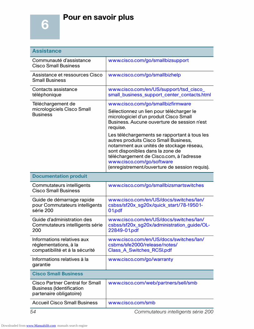
54 Commutateurs intelligents série 200
Pour en savoir plus
Assistance
Communauté d’assistance Cisco Small Business
www.cisco.com/go/smallbizsupport
Assistance et ressources Cisco Small Business
www.cisco.com/go/smallbizhelp
Contacts assistance téléphonique
www.cisco.com/en/US/support/tsd_cisco_ small_business_support_center_contacts.html
Téléchargement de micrologiciels Cisco Small Business
www.cisco.com/go/smallbizfirmware
Sélectionnez un lien pour télécharger le micrologiciel d’un produit Cisco Small Business. Aucune ouverture de session n’est requise.
Les téléchargements se rapportant à tous les autres produits Cisco Small Business, notamment aux unités de stockage réseau, sont disponibles dans la zone de téléchargement de Cisco.com, à l’adresse www.cisco.com/go/software (enregistrement/ouverture de session requis).
Documentation produit
Commutateurs intelligents Cisco Small Business
www.cisco.com/go/smallbizsmartswitches
Guide de démarrage rapide pour Commutateurs intelligents série 200
www.cisco.com/en/US/docs/switches/lan/csbss/sf20x_sg20x/quick_start/78-19501-01.pdf
Guide d’administration des Commutateurs intelligents série 200
www.cisco.com/en/US/docs/switches/lan/csbss/sf20x_sg20x/administration_guide/OL-22849-01.pdf
Informations relatives aux réglementations, à la compatibilité et à la sécurité
www.cisco.com/en/US/docs/switches/lan/csbms/sfe2000/release/notes/Class_A_Switches_RCSI.pdf
Informations relatives à la garantie
www.cisco.com/go/warranty
Cisco Small Business
Cisco Partner Central for Small Business (Identification partenaire obligatoire)
www.cisco.com/web/partners/sell/smb
Accueil Cisco Small Business www.cisco.com/smb
6
Downloaded from www.Manualslib.com manuals search engine

Commutateurs intelligents série 200 55
Downloaded from www.Manualslib.com manuals search engine
Siège en AmériqueCisco Systems, Inc.170 West Tasman DriveSan Jose, CA 95134-1706États-Unishttp://www.cisco.comAssistance Petites et moyennes entreprises - États-Unis : 1-866-606-1866 (Appel gratuit, 24x7)Assistance Petites et moyennes entreprises - Numéros à l’international
Cisco, Cisco Systems et les logos Cisco et Cisco Systems sont des marques commerciales ou
déposées de Cisco et/ou de ses succursales aux États-Unis et dans d'autres pays. Toutes lesautres marques commerciales mentionnées dans ce document ou sur ce site Web
appartiennent à leurs propriétaires respectifs. L’utilisation du mot partenaire n’implique pas de
relation de partenariat entre Cisco et une autre société. (1002R)
© 2010 Cisco Systems, Inc. Tous droits réservés.
78-19596-01
Downloaded from www.Manualslib.com manuals search engine


