Embed Size (px)
Citation preview

Department of Mechatronics Systems Engineering Simon Fraser University 250-13450 102 Avenue
Surrey, BC V3T 0A3
604.785.7060 www.SF1engineering.com SF-1 Engineering
[email protected] @SF1engineering
#250-13450 102nd
Avenue
Surrey, British Columbia, V3T 0A3
Maureen Hindy
Faculty of Engineering, Simon Fraser University
Central City Galleria 4
July 29, 2013
Re: SF-1 Mechanical Final Technical Report
Dear Ms. Hindy,
The following document, SF-1 Mechanical Final Technical Report, outlines our capstone project
for MSE 411w. Our goal was to finish the design and start construction of the car over the 8
month capstone period. Our plan is to have to car ready to race at Formula SAE next May.
This proposal will provide an overview of the final design and construction, financial analysis
which includes competition, transportation and building costs. Furthermore, the sources of
sponsorship and funding will be outlined with detailed information on project scheduling. The
design choices will be explored and thoroughly explained, along with the shortcomings and
roadblocks that the team encountered along the way.
Our Mechanical design team consists of four multi-talented individuals: Batuhan Atalay, George
Ioannou, Richard Douglas and Spencer Steele. Each team member brings his own set of skills
and experience to the team. As 4th
year capstone students, we are all very determined and
motivated to leave a legacy at SFU.
Sincerely,
George Ioannou
Batuhan Atalay
Richard Douglas
Spencer Steele
SF-1 Mechanical Design Team
Enclosure: SF-1 Mechanical Final Technical Report

July 29, 2013
Richard Douglas 301101340
Spencer Steele 301088654
George Ioannou 301092041
Batuhan Atalay 301099145
SF-1 Mechanical
Final Technical Report

i
EXECUTIVE SUMMARY
The final technical report outlines the specific components that have been designed, fabricated
and installed in the first SF-1 car. The sections covered are the chassis, suspension, powertrain,
drivetrain, steering and brakes. Within the large sections are the details and design methods that
have been implemented through the previous 8 months of this Capstone project.
The team budget is highlighted showcasing the partnerships formed to date, how the budget has
been utilized thus far and future predictions on additional costs including those of the race events
in 2014 and additional part/space needs.
The powertrain consists of a 600cc Yamaha engine with a 6-speed transmission and the
drivetrain is equipped with a torsen differential and provides a 3.5:1 gear ratio. The steering rack
is mounted near the dashboard to allow the maximum amount of space for the driver to reach and
operate the foot pedals. The steering wheel is a lightweight gokart wheel that has the
compatibility for the future integration of paddle shifters.
The control arms are made from alloy steel and connected to the chassis using spherical joints
(ball ends). Rigorous testing with FEA in Solidworks was conducted to prove the strength
characteristics. The shocks and springs are Fox Vanilla RC mountain bike shocks and are
mounted one per wheel provided independent suspension.
Providing driver safety are the brakes that consist of Brembo calipers, Willwood master
cylinders and are providing stopping power to custom fabricated rotors. Additionally, due to the
large inclination of the driver’s seat a 6-point harness is used to secure the driver to the seat.
All of the components come together and are assembled on an aluminum monocoque chassis
fabricated using 6061 T6 aluminum. Aluminum was chosen as the foundation of the majority of
our components due to its high strength and extremely light weight characteristics.

ii
TABLE OF CONTENTS
1.0 Definition of Terms iv
2.0 Introduction 1
3.0 Timeline 2
Long Term Product Goals & Schedule 2 3.1
4.0 Budget 4 Build and Marketing Budget 4 4.1
6.0 Power Train 5
Engine 5 6.1
Transmission 8 6.2
7.0 Drive Train 10 Drive Train Components 10 7.1
8.0 Suspension 13 General Suspension 13 8.1
Suspension Components 14 8.2
Miscellaneous 17 8.3
9.0 Steering 18
General Steering 18 9.1
Steering Components 19 9.2
10.0 Brakes 21 General Specifications 21 10.1
Brake Components 21 10.2
11.0 Wheels and Tires 23
12.0 Chassis 24
Design & Stress Analysis 24 12.1
13.0 Key Technologies, and Safety & Other Features 30 Safety Integration 30 13.1
Key Technologies 31 13.2
14.0 Conclusion 33
15.0 References 34
Appendix A: Sample Sponsorship Package (Circulated to potential sponsors) 36
Appendix B: Bill of Materials 38
Appendix C: Suspension 40

iii
TABLE OF FIGURES
Figure 1: Production Timeline 3
Figure 2: The powerful Yamaha YZF 600 Engine, in our bespoke engine test stand at our Auto
Show booth 5
Figure 3: Sample dynamometer readout for YXF-R6 engine 6
Figure 4: An example Fuel Restriction System (Designed by Dalhousie FSAE Team) 6
Figure 5: -AN Fittings with Braided Stainless Steel Fuel Lines 7
Figure 6: One of the Twin Side Mounted Aluminum Radiators 8
Figure 7: An FSAE Competitor’s Paddle Shifter Design 9
Figure 8: Differential Assembly including rear brake caliper 10
Figure 9: Typical constant velocity shaft 10
Figure 10: Aluminum CV Tripod Housing 11
Figure 11: Output sprocket - 3.5:1 Ratio 11
Figure 12: Exploded View of Differential Assembly 12
Figure 13: Typical FSAE front suspension [photo credit: MotoIQ.com] 13
Figure 14: Rendering of SF-1 front suspension (pushrod delete) 15
Figure 15: Rendering of SF-1 Rear Suspension (pushrod delete) 15
Figure 16: Rendering of SF-1 Front Bellcrank 17
Figure 17: Original Steering Design 18
Figure 18: Ackermann Geometry 19
Figure 19: Woodward Type MC Rack & Pinion Steering Shaft 20
Figure 20: New steering design 20
Figure 21: Wilwood brake components with custom set-up 21
Figure 22: Wilwood GP200 Brake Caliper 22
Figure 23: Cross-drilled & slotted brake rotor 22
Figure 24: SolidWorks rendering and photo of SF-1 rims for rain tires 23
Figure 25: Preliminary Chassis Rendering - March 28 2013 25
Figure 26: FEA Analysis on the Chassis in SolidWorks 26
Figure 27: Finalized Chassis Design 27
Figure 28: Chassis under construction in a Jig 28
Figure 29: Welding the Chassis 28
Figure 30: Chassis nearing completion - July 15 2013 29
Figure 31: Minimum roll hoop clearance 30

iv
1.0 DEFINITION OF TERMS
Alternative frame A frame which differs from a steel space frame in either material or
design, or both.
Bulkhead That frame section, resembling a planar section, which is situated
immediately forward of the driver’s foot controls.
Control Arm In a suspension system, connects the steering knuckle with the chassis
and locates each axle. A suspension requires top and bottom control arms
at each applicable corner of the car. AKA “wishbone,” “A-arm.”
DOHC Dual Overhead Camshaft or Double Overhead Camshaft.
FEA Finite Element Analysis; a numerical form of stress analysis normally
used when analytical stress analysis might be prohibitively complex or
impossible.
Front roll hoop The hoop installed over the driver’s legs to protect the driver in case of a
rollover.
FSAE Formula SAE, the competition into which SF-1 is entering.
Main roll hoop The steel tubing hoop installed over/behind the driver’s head to protect
the driver in case of a rollover.
Master cylinder The component of the brake system which converts force applied to the
brake pedal by the driver to hydraulic brake pressure for purposes of
activating the service brakes.
SAE Society of Automotive Engineers
Slicks A term generally used for a racing tire.
SPST Single pole, single throw (electrical switch classification).
SRCF Structural Requirements Certification Form, a document outlining the
performance analysis which might be performed on an alternative frame.
Throttle A device used for metering air intake, and subsequently, fuel intake, to
the engine; controlled by accelerator pedal.
Track The measurement from the center of one wheel to the center of the
opposite wheel on the same axle.
Upright The piece of a control arm suspension which links the top and bottom
arms, as well as provides a mounting point for the bearing hub.
Wheelbase The measurement from the center of the front wheels to the center of the
rear wheels.

1
2.0 INTRODUCTION
This Final Technical Report marks a significant milestone in the overall design and construction
of the SF-1 race car. As expected, the mechanical division faced a significant design task,
fraught with challenges. Many of the designs aspects revolve around the parts which need to be
sourced for various sub-systems. Sourcing parts is fast becoming an attractive option for our
team as opposed to fabrication, as time is a significant constraint. In many cases, sourcing parts
from retail vendors proves to be less expensive than custom fabrication.
Due to the many sub-systems in the SF-1 car, the team must undertake a high-level design
perspective. As such, many sub-section details in this report involve the specification of parts
which are available from distributors, several of whom sponsor the SF-1 team. Also pertaining
to this fact, some sub-systems for which engineering is not yet completed are outlined rather than
specified. In these cases, constraints are given in place of dimensions.
2
3.0 TIMELINE
Long Term Product Goals & Schedule 3.1
The major goal of the team was to establish an FSAE team at SFU. We feel we have done well in
accomplishing this goal. From this point onwards the main goal it to finish fabrication on the car
and start testing with a couple months to spare prior to the Michigan and Nebraska competitions.
As seen on the timeline below (figure 4), the design on the major systems of the car is already
complete. Chassis and powertrain design is complete and fabrication and machining has begun at
both the MRX Marine shop and MSE Machining and Testing Center. The suspension, steering,
brake and body fabrication will start mid-August and continue on into the beginning of
September at which point the overall assembly and integration will begin.
Assembly and integration should take the team well into the middle of October. This period of
time may be prolonged if parts do not pass track testing. By the end of October, testing should
commence before the rainy season starts and track conditions are not ideal. The testing will most
likely carry on for a matter of months along with iterative design on parts that do not work out.
The Michigan Competition takes place from May 8-11th 2014 and the Nebraska competition
takes place May 18th
-22nd
. An additional 3 days must be allocated for transporting the car to
competition as well as a consecutive 3 for transporting it back after competition.

3
Figure 1: Production Timeline
Space Acquisition
Lincoln Competition
Michagan Competition
Testing
Overall Assembly & Integration
Body FabricationBody Design
Brake & Steering FabricationBrake & Steering Design
Suspension FabricationSuspension Design
Powertrain MachiningPowertrain Design
Chassis FabricationChassis Design
SF-1 Timeline
Design DaysCompleted
Design DaysRemaining
Fabrication DaysCompleted
Fabrication DaysRemaining
Assembly Time
Testing Time
Competition
Planning
Renovations
4
4.0 BUDGET
Build and Marketing Budget 4.1
At these final stages of the project SF-1 has accumulated over 15 sponsors and funding in the
range of $10,000 (this includes part discounts and donations). Some of our companies include:
Lordco who provides substantial discounts on parts, Knighthill Automotive who has offered to
paint and detail our bodywork, BatteryWorld who donated a custom motorcycle battery and
many more. A detailed list of all the sponsors can be found in Appendix A. Purchases made to
date for all the components that are outlined through the report have cost roughly $7000 with a
detailed breakdown presented in Appendix B. Our costs include those of machine shop hours,
material stock, fasteners and marketing methods (t-shirts, business cards etc.). Future costs have
been predicted and we are still within our budget of $10,000 with roughly $3,000 remaining and
several sponsorships still pending. For a project such as this, business and marketing aspects are
ongoing and new partnerships are continuously being sought after.
Event Costs 4.2
Event costs have been estimated using information from the SAE website and also from research
we conducted on the internet. The value on the table includes a $2000 entry fee, projected fuel
transportation costs to/from Nebraska, trailer rental fees, hotel bookings, and food. In
consideration that we will be competing in 2014 we understand that these costs might vary at the
time of competition. Hotel pricing was found using online booking websites and estimating
prices for the competition period in 2014.

5
6.0 POWER TRAIN
Engine 6.1
6.1.1 General Specifications
610cc is the maximum engine displacement allowed in competition. We chose a Yamaha YZF-
600R motorcycle engine for a number of reasons. The Yamaha 600cc is one of the best
engineered engines around that is relatively close to our maximum engine displacement. Parts
for it can be found off the shelf relatively easily and inexpensively.
The SF-1 team uses a bespoke, student-built test stand for storage and testing purposes when the
engine is out of the car, shown here on display at the 2013 Vancouver International Auto
Show:
Figure 2: The powerful Yamaha YZF 600 Engine, in our bespoke engine test stand at our Auto Show booth
Our 599cc displacement combined with liquid cooling, DOHC, and 16 valve configuration make
it a very responsive engine perfect for high performance applications. The Yamaha 600 also has
a very nice power curve 10
as seen in figure 1, below:

6
Figure 3: Sample dynamometer readout for YXF-R6 engine
The stock engine is capable of outputting 85 horsepower under normally aspirated conditions.
Our engine came stock with a set of 4 single barreled carburetors. Carburetion is our existing
method of fuel delivery but we have plans to upgrade later to a custom mega squirt fuel injection
system complete with a mapable ECU.
6.1.2 Intake Restrictor
Because of competition rules, all intake air to the engine must pass through a 20mm diameter
circular ring which will be the last point of contact for the flowing air before it is delivered into
the individual intake valves of the cylinders. This restrictor will be installed between the
throttling device and the cylinder head. Carbon fiber and aluminum will likely be the material of
choice for their weight properties.
Figure 4: An example Fuel Restriction System (Designed by Dalhousie FSAE Team)

7
6.1.3 Fuel Supply & Delivery
The fuel tank itself is designed out of 1/8” aluminum sheet metal and features a site tube and
manual fuel cap as required by competition rules. The overall fuel capacity of 2 gallons will
supply more than enough fuel for even the most gruelling events (i.e. FSAE Endurance).
Hard stainless steel fuel lines will be used in combination with flexible fuel hose to deliver the
fuel from the tank to the carburetion system. Military grade AN Fuel fittings will be used
wherever possible to ensure fuel system reliability and integrity. These will be designed and
installed after most of the other major components. The fuel system will also feature an inline
racing fuel pump with a replaceable FRAM fuel filter that can be easily inspected before races.
Figure 5: -AN Fittings with Braided Stainless Steel Fuel Lines
6.1.4 Cooling System
To cool the engine, two 12.5”x15” aluminum radiators will be located on either side of the
engine in line with the main roll hoop. The chassis will provide not only structural support but
airflow to the radiators using a unique formula one style duct. Both radiators come equipped with
cooling fans which will keep the engine at an optimum operating temperature while idling in a
hot Michigan spring on the tarmac.

8
Figure 6: One of the Twin Side Mounted Aluminum Radiators
Transmission 6.2
6.2.1 General Specifications
One of the reasons we decided to go for a motorcycle engine was because they are already
designed with a complete gear transmission. In our case, the Yamaha engine is coupled to a 6
speed sequential transmission. This will provide a wide range of operating speeds at which the
car can be driven through variable track setups.
6.2.2 Shifting
A custom paddle shift system is being designed for the original Yamaha 6 speed transmission.
While still in the preliminary design stages, the plan is to incorporate a stepper motor and a gear
reduction system to take the place of shifter linkage. Shift Paddles will be located behind the
steering wheel.
9
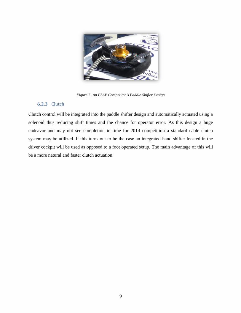
Figure 7: An FSAE Competitor’s Paddle Shifter Design
6.2.3 Clutch
Clutch control will be integrated into the paddle shifter design and automatically actuated using a
solenoid thus reducing shift times and the chance for operator error. As this design a huge
endeavor and may not see completion in time for 2014 competition a standard cable clutch
system may be utilized. If this turns out to be the case an integrated hand shifter located in the
driver cockpit will be used as opposed to a foot operated setup. The main advantage of this will
be a more natural and faster clutch actuation.

10
7.0 DRIVE TRAIN
Drive Train Components 7.1
7.1.1 Differential
The power distribution to our rear wheels will be done using an Audi A4 Torsen differential with
helical gears. The differential has already been sourced from a donor car, so specifying the
materials used in its construction would be
redundant. Additionally, the differential case is
presumably made from a different material than the
internals.
Torsen differential of this category are exceptional
for increasing internal friction. This is used for
higher torque applications but can lead to rare
instances of backlash occurring. The Torsen design
allows for a speed differential effect when cornering,
such that the outer wheel rotates at a higher velocity than the inner, while more torque is applied
to the inner wheel.
The Torsen housing will also be used to mount the rear brake. Instead of mounting an individual
brake on each of the rear wheels, a single inboard brake on the output gear itself is used. The
limited-slip operation of the Torsen means that applying the brakes will stop the rotation of the
output gear, stopping both rear wheels simultaneously. In the figure above you can see a
rendering of the differential and the housing that encompasses it. The 5-finger plate that is visible
on the front is where the sprocket for the chain drive is mounted.
7.1.2 CV Shafts
Refer to the following diagram. The CV (constant
velocity) shafts consist of a steel shaft (B in the
diagram) with a male spline on each end. Between the
centre shaft and each end spline is a CV joint. Each Figure 9: Typical constant velocity shaft
Figure 8: Differential Assembly including
rear brake caliper

11
joint is a different type: the inner joint is a tripod joint (C), which can be modeled as a revolute
joint in series with a prismatic joint to allow the CV shaft to change length as the suspension
articulates. The outer joint is a Rzeppa-type joint (A), which is purely revolute.
To save weight while handling high torque, the
shaft will be constructed of alloy steel. The
splines will both be heat-treated to ensure
sufficient surface hardness for wear resistance.
Replacing the tripod housing located between B
and C above is the custom housing that you see
on your right (Figure 10). This aluminum
housing is bolted directly onto the output of the
torsen differential and does not require the use of
the male splines at C. By doing so, the team was able to reduce the weight of the assembly even
further and implement another aspect of innovation.
7.1.3 Chain Drive
Our final drive ratio is a pleasant midpoint
between quick acceleration and top-line speed.
Through optimization in regards to size of the
sprocket and top speed it was selected at 3.5:1.
The sprocket is mounted on the 5-finger plate that
is shown in Figure 8 above and also acts as the
rotor for the rear brake. The sprocket is made
from steel alloy to ensure that it can withstand the
constant torque loading while also enduring the
high temperature variations caused by braking. It
is ¼” thick and weighs ~5lbs. A chain drive system
requires regular lubrication and a braking surface must be dry at all times therefore a regular
motorcycle chain is not compatible as it would coat the sprocket in chain lubricant rendering the
brake inactive. To solve this issue a #530 O-ring chain has been installed. The chain has rubber
Figure 10: Aluminum CV Tripod Housing
Figure 11: Output sprocket - 3.5:1 Ratio
12
O-rings built between the outside link plate and inside roller link plates. These rubber fixtures
form a barrier that holds factory applied lubricant grease inside of the pin and bushing wear
areas. This eliminates the need for manual lubrication and also prevents external contaminants
including dirt to enter the inside of the chain linkages where such particles could lead to
increased wear and a shortened product life.
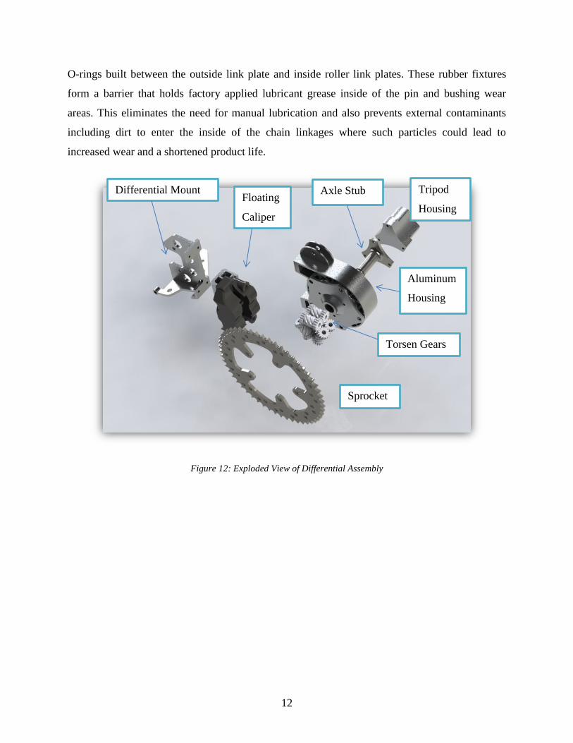
Figure 12: Exploded View of Differential Assembly
Differential Mount
Sprocket
Tripod
Housing
Axle Stub
Aluminum
Housing
Torsen Gears
Floating
Caliper

13
8.0 SUSPENSION
General Suspension 8.1
The SF-1 suspension will use a double-wishbone setup front and rear. The basic design of this
layout has been the staple of international Formula-1 teams for years, and the innovation has
trickled down to the amateur classes. The shock/ spring assembly at each corner is actuated via a
push rod, ligntening the articulating mass as opposed to using an outboard coil-over. For a
sample illustration, see the following diagram:
Figure 13: Typical FSAE front suspension [photo credit: MotoIQ.com]
The letters A-E will be used in reference to this drawing throughout the description of the

14
Suspension Components 8.2
8.2.1 Control Arms
The control arms (E in the above diagram) are made of mild steel and connected to the chassis
using spherical joints (ball ends). Alloy steel was originally specified, but after completing
stress analysis on the suspension, we found that mild steel would maintain a reasonable factor of
safety. Due to its being much cheaper than alloy alternatives, mild steel was selected. All rod
ends and spherical bearings; as well ¼ pipe (sch. 40) has been ordered and shipped; fabrication
will begin on the suspension once the chassis is complete.
The following specifications apply to the control arms in general:
1. The front track is set to 53”; the rear, 51”. This complies with the FSAE regulation that
rear track is within 75% of front track.
2. The spherical joints and bell cranks are loaded in double shear.
The following notes apply to the front control arms only:
1. Staying within the track width requirement, there is a minimum of 16” between the pick-
up points of left and right side control arms to allow room for the driver’s feet and foot
controls.
2. The geometry has been designed such that undesirable performance, such that jacking
effect and bump steer, is reduced as much as possible during cornering. Ideally, the
outside tire undergoes a negative camber attitude.
The following notes apply to the rear control arms only:
1. Staying within the 51” track specification, is a minimum of 26” between the pick-up
points of left and right side control arms to allow room for the powertrain.
2. Because the driver receives all steering input from the front wheels, no scrub radius or
caster angle is necessary for the rear suspension. The geometry has therefore been
engineered such that there is a minimum scrub radius and caster in the rear, although this
is slightly compromised by the wheels being used.
3. The geometry has been designed such that undesirable performance, such that jacking
effect, is reduced as much as possible during cornering.

15
Figure 14: Rendering of SF-1 front suspension (pushrod delete)
Figure 15: Rendering of SF-1 Rear Suspension (pushrod delete)
16
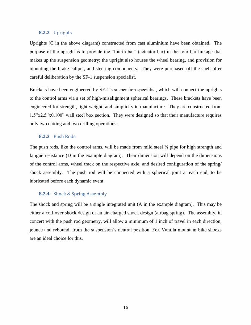
8.2.2 Uprights
Uprights (C in the above diagram) constructed from cast aluminium have been obtained. The
purpose of the upright is to provide the “fourth bar” (actuator bar) in the four-bar linkage that
makes up the suspension geometry; the upright also houses the wheel bearing, and provision for
mounting the brake caliper, and steering components. They were purchased off-the-shelf after
careful deliberation by the SF-1 suspension specialist.
Brackets have been engineered by SF-1’s suspension specialist, which will connect the uprights
to the control arms via a set of high-misalignment spherical bearings. These brackets have been
engineered for strength, light weight, and simplicity in manufacture. They are constructed from
1.5”x2.5”x0.100” wall steel box section. They were designed so that their manufacture requires
only two cutting and two drilling operations.
8.2.3 Push Rods
The push rods, like the control arms, will be made from mild steel ¼ pipe for high strength and
fatigue resistance (D in the example diagram). Their dimension will depend on the dimensions
of the control arms, wheel track on the respective axle, and desired configuration of the spring/
shock assembly. The push rod will be connected with a spherical joint at each end, to be
lubricated before each dynamic event.
8.2.4 Shock & Spring Assembly
The shock and spring will be a single integrated unit (A in the example diagram). This may be
either a coil-over shock design or an air-charged shock design (airbag spring). The assembly, in
concert with the push rod geometry, will allow a minimum of 1 inch of travel in each direction,
jounce and rebound, from the suspension’s neutral position. Fox Vanilla mountain bike shocks
are an ideal choice for this.
17
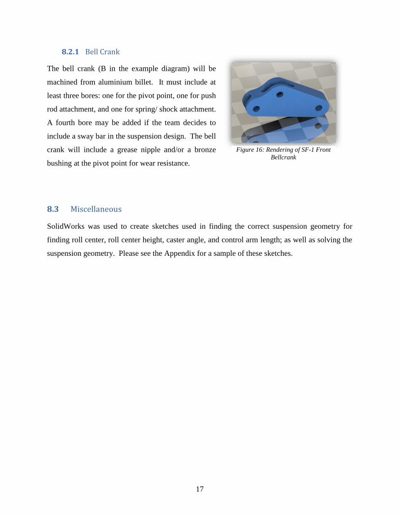
8.2.1 Bell Crank
The bell crank (B in the example diagram) will be
machined from aluminium billet. It must include at
least three bores: one for the pivot point, one for push
rod attachment, and one for spring/ shock attachment.
A fourth bore may be added if the team decides to
include a sway bar in the suspension design. The bell
crank will include a grease nipple and/or a bronze
bushing at the pivot point for wear resistance.
Miscellaneous 8.3
SolidWorks was used to create sketches used in finding the correct suspension geometry for
finding roll center, roll center height, caster angle, and control arm length; as well as solving the
suspension geometry. Please see the Appendix for a sample of these sketches.
Figure 16: Rendering of SF-1 Front
Bellcrank

18
9.0 STEERING
General Steering 9.1
The steering saw substantial alterations since the beginning of the design stage. The biggest
change happened in the overall steering design concept. Originally, we planned to have a floor
mounted steering rack with a double u-joint shaft coupling it to the steering wheel. Because of
the lack of space in the nose compartment of the vehicle, and the need to reach the throttle and
brake pedals comfortably, we decided to remove the steering rack from its original location on
the floor, and mount it close to the dashboard with the help of a bracket. This created more space
in the nose compartment, and also eliminated the need for a complicated shaft coupling system.
Figure 17: Original Steering Design
The trade-off of this design alteration was the need to calculate new steering knuckles, as well as
re-work the steering geometry in order to satisfy Ackermann steering.

19
Ackermann Steering is the geometric design of the steering system where the front tires are able
to turn at different angles in order to complete a turn without over or under-steering. The steering
arms and the tie-rod angles were designed with the Ackermann geometry in mind.
Figure 18: Ackermann Geometry
Steering Components 9.2
9.2.1 Steering Rack
Modern road vehicles have complex steering systems. These are designed around the comfort of
the driver and include components as hydraulic steering, adjustable steering columns, etc.
Having the lightweight of our vehicle in mind, we resorted to a non-hydraulic system.
A manual rack-and-pinion steering rack was sourced from BMS Inc. This steering rack offered
all our design criteria, as it was a manual rack with a centre mounted shaft. It also offered the
rack ratio necessary (3.4in/rev) for hard, auto-cross steering geometry.

20
Figure 19: Woodward Type MC Rack & Pinion Steering Shaft
9.2.2 Tie Rods
We used suspension tie-rods to mount to the steering rack, as we had the option of using any
threaded tie-rod that would satisfy the geometry. The same size tie-rods came in very handy, as
we were able to fabricate many of our suspension and steering geometries without having to
source new parts.
9.2.3 Steering Wheel & Shaft
A lightweight steering wheel was sourced online and coupled to a quick release unit, which we
purchased from Dan’s Performance Parts. The steering shaft was chosen to be 5/8” in diameter
in order to match the steering rack output shaft.
Figure 20: New steering design

21
10.0 BRAKES
General Specifications 10.1
Braking is a vital component of any automobile, and safety is the primary concern of the FSAE
competition. Therefore the brakes must have the capability of stopping the car from speeds in
excess of 200 km/h within a very short distance. One of the key ways we reduced more weight
on the car will be to run a pair of disc brakes on the front wheels while only using a single
differential mounted disc brake. This simplifies the design by removing the additional brake and
reduces the overall weight of the car, as well as the unsprung mass of the rear suspension. The
braking system is broken down into the following sections: master cylinder, calipers, pads,
rotors, and brake lines.
Brake Components 10.2
10.2.1 Master Cylinder
Two individual pedals were purchased from Wilwood for actuating the throttle and the brakes.
Both master cylinders are actuated from the same brake pedal by running them tandem with a
custom bracket. These master cylinders control the front and rear brake lines, and their pressure
will be adjusted dynamically, in order to get proper braking from both axles.
Figure 21: Wilwood brake components with custom set-up

22
10.2.2 Calipers & Pads
Individual brake calipers provide the
braking on the front wheels while the
rear will be stopped by one larger
central mounted caliper. For the front,
we chose the Brembo P34 calipers
which are lightweight and have large
cylinders that can handle up to 11” to provide the performance braking SF-1 requires. Stock pads
will be used with the P34 calipers
A stock Tokico dual piston caliper normally found on Honda 600cc street bike will be used on
the rear sprotor. Stock pads will be the braking pad of choice.
10.2.3 Rotors
All brake rotors are custom designed to fit inside our wheel
opening, and match the bolt pattern of the wheels. 10” OD
drilled steel rotors were custom laser cut and used to transfer
braking power from the calipers to the front wheels. 10”
rotors will provide the greatest contact surface area while still
fitting within our 13” wheels.
The rear brake rotor was custom designed to double as a
differential sprocket. It was designed and cut out of high strength
stainless steel using a water jet machine at G.A. Industries.
10.2.4 Brake Lines & Proportioning Valve
Stainless Steel brake lines were used to deliver hydraulic pressure from the pedal mounted
master brake cylinder to the P34 calipers mounted front and rear on the car. An adjustable
proportioning valve will be installed to balance the front and rear caliper pressure.
Figure 23: Cross-drilled &
slotted brake rotor
Figure 22: Wilwood GP200 Brake Caliper

23
11.0 WHEELS AND TIRES
11.1.1 Wheels
Our wheels will be 13x8” Toms Racing Igeta wheels made out of magnesium. They aid in
minimal overall weight of the car with each wheel and tire assembly weighing only 22lbs.
Another reason for choosing these wheels is the fact that they have a 4-bolt pattern and allow us
to easily find an aftermarket hub that will fit them. Our decision was between these wheels and
another 13” centerlock wheel but due to the time constraints of the project we would not be able
to custom design a centerlock hub for those wheels. The figure shows a SolidWorks model of the
wheel without the tire.
Figure 24: SolidWorks rendering and photo of SF-1 rims for rain tires
11.1.2 Tires
The tires we will use for testing on local tracks will be Sumitomo performance low profile rain
tires. Due to the weather in the lower mainland the majority of our test drives will be done in wet
conditions and these will be the perfect tires until more serious pre-competition preparation
begins. At that point we will swap the current tires over to Hoosier 20.0x7.5-13 or Goodyear
20.0x7.0-13 dry slicks for maximum traction in dry conditions found at the American tracks.

24
12.0 CHASSIS
Design & Stress Analysis 12.1
Arguably the single most important part of the car, the chassis ties all of the separate
subsystems together into a fully functioning race car. Our team considered three major designs
for the chassis: steel space frame, aluminium space frame, and aluminium monocoque. In the
end, a hybrid was designed combining features of an aluminum space frame with that of an
aluminum monocoque. To set ourselves apart from the rest of the competition we have chosen to
fabricate our chassis out of 6061-T6 Aluminum. Aluminum was the material of choice for its
lightweight characteristics and its weldability. The weight of the chassis is approximately 50 lbs,
about 25% lighter than traditional steel space-frames similarly seen in competitions.
Unfortunately this choice had its drawbacks; the strength of aluminum is significantly less than
that of chromoly or even mild steel. To counteract this 6061-T6 Aluminum alloy was selected.
The 6061 is an alloy typically used is the aerospace industry, the T-6 heat treatment designation
is the highest available and gave an ultimate strength of 300 MPa. Provisions have been put in
place to have the chassis heat treated at Van Heat to the T-6 strength after all of the welding and
fabrication is complete, this will realign the ions in the material and in turn increasing the overall
strength of the chassis.
The chassis changed substantially over the first 6 months of the capstone. The amount of time
spent on chassis design was so long because it was an iterative process. In order to ensure all of
the components will fit, all of those components themselves had to be modelled. To start with, a
basis chassis design had to be adopted while other components were finished. A preliminary
chassis rendering can be seen below in Figure 25.

25
Figure 25: Preliminary Chassis Rendering - March 28 2013
In order to meet strict safety requirements while encouraging innovative design, FSAE
allows alternative frame construction using unique materials and non-traditional fabrication
techniques. To meet these safety standards, a Structural Requirements Certification Form
(SRCF) must still be completed. After the final chassis geometry was determined, Finite
Element Analysis (FEA) will be used to further evaluate the structural equivalency of the design.
Due to the intense geometry of the structure and many hours of troubleshooting we gave up on
using ANSYS Workbench and APDL software. We followed some SolidWorks Tutorials on
Youbtube specific to FSAE chassis design and quickly found it was much more efficient to
perform the analysis in SolidWorks using the included simulation package.

26
Figure 26: FEA Analysis on the Chassis in SolidWorks
After FEA Analysis and all of the other major system components were modeled the chassis
design was able to be finalized. As seen below, the chassis assembly is made of 3 major sections,
the main chassis which encloses the driver and extends from the front bulkhead (the plate at the
front) to the main roll hoop. The rear subframe is the boxed section rear of the main roll hoop.
The roll hoop itself must be made out of mild steel in order to comply with FSAE rules and will
be a bolt on component. The reason for separating the chassis into separate parts is mainly due to
the size restriction of Van Heat’s furnaces. The separate rear subframe eases engine installation
and removal. A noticeable feature of the final chassis is the updated side structure which flows
air to the dual rear mounted radiators as well as provides structural support for them. The flat
panels and sharp contours were designed with sheetmetal fabrication in mind and give the car a
“stealth fighter” look adding to the aesthetic appeal and originality.

27
Figure 27: Finalized Chassis Design
Chassis Fabrication 12.2
Chassis fabrication started at the end of June and is almost complete to date with the exception of
suspension control arm mounts and radiator supports. The following photos in this section show
fabrication as of mid-July at the MRX Marine shop. The chassis fabrication consisted of cutting
the material to length, grinding and notching the material to fit, and finally welding the different
sections together. 6061-T6 Aluminum was ordered prior to fabrication in stock 20’ lengths. The
majority of the chassis is constructed of round cornered square 1.5” or 1” cross section with
0.120” wall thicknesses.

28
Figure 28: Chassis under construction in a Jig
Figure 29: Welding the Chassis
To create the complex geometry that makes up the chassis, key components were constructed
individually using jigs. Jigs are fixtures that constrain the material from moving while welding is
performed. Once the welding on the component was finished and the material had cooled it was
removed from the jig and placed in a new jig prior to more welding. Piece by piece the chassis
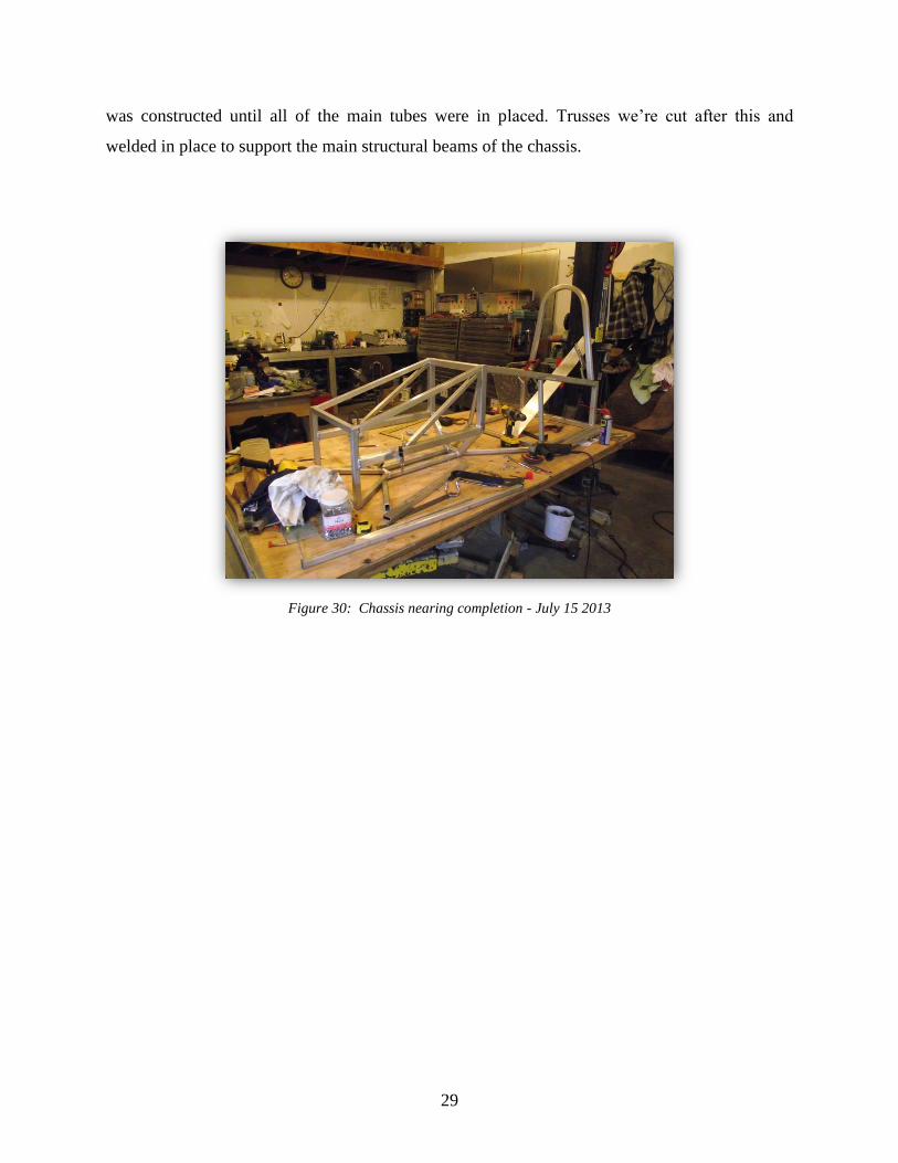
29
was constructed until all of the main tubes were in placed. Trusses we’re cut after this and
welded in place to support the main structural beams of the chassis.
Figure 30: Chassis nearing completion - July 15 2013
30
13.0 KEY TECHNOLOGIES, AND SAFETY & OTHER FEATURES
Safety Integration 13.1
13.1.1 Roll Hoop Requirements
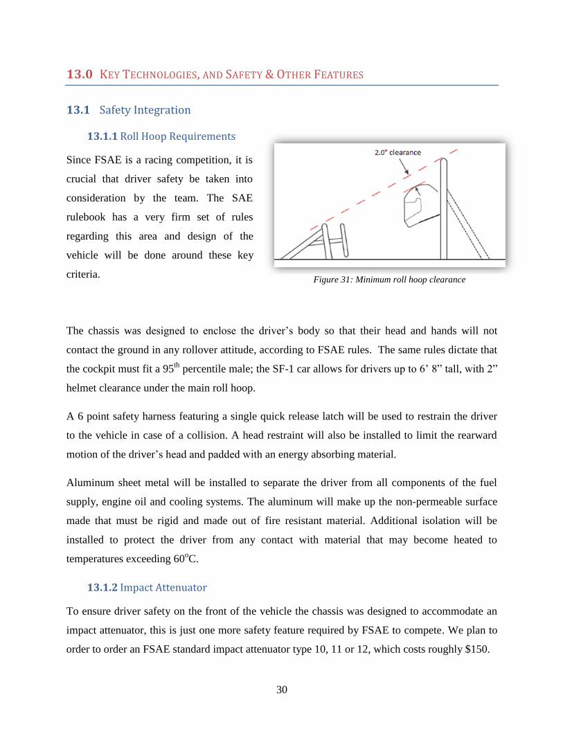
Since FSAE is a racing competition, it is
crucial that driver safety be taken into
consideration by the team. The SAE
rulebook has a very firm set of rules
regarding this area and design of the
vehicle will be done around these key
criteria.
The chassis was designed to enclose the driver’s body so that their head and hands will not
contact the ground in any rollover attitude, according to FSAE rules. The same rules dictate that
the cockpit must fit a 95th
percentile male; the SF-1 car allows for drivers up to 6’ 8” tall, with 2”
helmet clearance under the main roll hoop.
A 6 point safety harness featuring a single quick release latch will be used to restrain the driver
to the vehicle in case of a collision. A head restraint will also be installed to limit the rearward
motion of the driver’s head and padded with an energy absorbing material.
Aluminum sheet metal will be installed to separate the driver from all components of the fuel
supply, engine oil and cooling systems. The aluminum will make up the non-permeable surface
made that must be rigid and made out of fire resistant material. Additional isolation will be
installed to protect the driver from any contact with material that may become heated to
temperatures exceeding 60oC.
13.1.2 Impact Attenuator
To ensure driver safety on the front of the vehicle the chassis was designed to accommodate an
impact attenuator, this is just one more safety feature required by FSAE to compete. We plan to
order to order an FSAE standard impact attenuator type 10, 11 or 12, which costs roughly $150.
Figure 31: Minimum roll hoop clearance

31
13.1.3 Jacking Point
After the car is closer to completion, a jacking point will be fabricated out of aluminum and
mounted to the rear of the vehicle to allow quick access to the underside of the vehicle by
maintenance crews or judges. The jacking point will be designed as is later on. It will be painted
orange for high visibility in all situations.
Key Technologies 13.2
A certain level of technological advancement is expected in motorsports. Indeed, the sport is a
showcase for some of the great developments that trickle down to consumer automotive fields.
Below is a short list of some of the high-tech features of the First-Generation SF-1 offering:
13.2.1 Lithium Ion Battery
Relatively new to powersports, Lithium Ion technology is making leaps and bounds in the
industry. Our use of this technology over Lead-Acid means to an instant weight savings of 9 lbs.
13.2.2 Skinned Space Frame Chassis
A concept that is similar to a monocoque but incorporates the ease of tubular chassis fabrication
with the additional rigidity and lighter weight afforded by integrated body panels.
13.2.3 LCD Display with Data logging Capabilities
The Racer’s Edge LCD dashboard and data logging system is a main selling point for the
SF-1 team’s technical expertise. A standalone system used for logging performance figures, this
masterpiece of engineering is a bespoke design by the SF-1 Electronics division. It is used
during races and test runs for the purpose of holistic vehicle tuning, allowing the driver and pit
crew to squeeze the last ounce of performance from every lap.
Similar systems exist on the market and are being used by competing race teams. However,
these systems frequently cost upwards of $4000 and offer limited customizability. The SF-1
system, on the other hand, is a student-designed system, resulting in a net cost to SF-1 of under
$500, and is easily customizable by members of our capstone team.

32
For more details of the LCD display and Datalogger, please refer to the appropriate
documentation from the SF-1 Electronics Division.5
13.2.4 Limited Slip Differential
Limited Slip Differential technology offers increased traction to both drive wheels and allows the
use of advanced braking systems in the rear. The SF-1 differential uses internals from Torsen,
Inc. and a custom-machined aluminium housing to save weight.

33
14.0 CONCLUSION
Thus far we have achieved many of our goals and accomplished many of the deliverables we
intended on showcasing by the end of our Capstone project. We like to believe that we have
started a long lasting legacy for SF-1 and its team members in the university racing industry. At
this point we are at the final stages of vehicle assembly as the bulk of the design work has been
finalized. The major components of the car (chassis, drivetrain, suspension and steering/brakes)
have been fabricated or are in the process currently. Seeing as this is a school club as well as a
capstone project several of the team members will continue to work on the vehicle while also
transitioning into a new executive team. Competition in 2014 is within grasp and we hope that
the majority of the team members will be able to attend. In addition, by building strong
relationships with industry partners we have ensured that the donations and discounts will be
ongoing and transferrable into future years. We expect more sponsors to be acquired as exposure
of the team increases through events such as the Vancouver International Auto show and others.
Our goals consist of having a completed prototype by October 2013, a car with over 90% of the
final components assembled and the car being drivable. Furthermore, we are currently working
with the Dean of Engineering and SFU in acquiring some designated shop space for SF-1 along
with other engineering teams here at SFU. We hope that when we transition the team to its new
members (mid-late September) we will have designated shop and storage space. Our options
currently are between the old Shell Service station on SFU Burnaby and off-site warehouse
rental space in a location between the Burnaby and Surrey campuses.

34
15.0 REFERENCES
Corporate Author: SF-1 Engineering: 2013. SF-1 Electrical: Design Specification for The
Racer’s Edge.
Corporate Author: SF-1 Engineering: 2013. SF-1 Mechanical: Design Specification For SFU’s
First Formula SAE Race Car. Course Requirements: Simon Fraser University, MSE400.
Corporate Author: SF-1 Engineering: 2013. SF-1 Mechanical: Functional Specification For
SFU’s First Formula SAE Race Car. Course Requirements: Simon Fraser University, MSE400.
Corporate Author: SF-1 Engineering: 2013. SF-1 Mechanical: Updated Business Proposal.
Course Requirements: Simon Fraser University, MSE400.
Corporate Authors: SF-1 Engineering et al. : 2013. Storage & Workspace Proposal for SFU
Engineering Teams.
MotoIQ.com. 24 August 2011. Website: Formula SAE: What a Few Car College Gear Heads
Can Do In Their Free Time. <http://www.motoiq.com/magazine_articles/id/
2072/pageid/3483/formula-sae- what-a-few-car-college-gear-heads-can-do-in-their-free-
time.aspx>
MotoIQ.com. 24 August 2011. Website: Formula SAE: What a Few Car College Gear Heads
Can Do In Their Free Time. <http://www.motoiq.com/magazine_articles/id/
2072/pageid/3483/formula-sae- what-a-few-car-college-gear-heads-can-do-in-their-free-
time.aspx>
Mott, Robert L. (2004). Machine Elements in Mechanical Design 4th
Edition .
Slocum, Jonathan M. MIT FSAE Racer. (Powerpoint Presentation). <web.mit.edu/jtslocum/
www/Documents/FSAE/Steering.pdf>
Society of Automotive Engineers. 22 November, 2012. FSAE 2013 Rules.
Summit Racing Equipment, Inc. (Online Catalogue). <www.summitracing.com>
Summit Racing Equipment, Inc. (Online Catalogue). <www.summitracing.com>
Wilwood Performance Brakes. (Manufacturer’s Data). <www.wilwood.com>
Woodward Steering, Inc. (Online Catalogue). <www.woodwardsteering.com>
Woodward Steering, Inc. (Online Catalogue). <www.woodwardsteering.com>
35
MotoIQ.com. 24 August 2011. Website: Formula SAE: What a Few Car College Gear Heads
Can Do In Their Free Time. <http://www.motoiq.com/magazine_articles/id/
2072/pageid/3483/formula-sae- what-a-few-car-college-gear-heads-can-do-in-their-free-
time.aspx>
Woodward Steering, Inc. (Online Catalogue). <www.woodwardsteering.com>
Summit Racing Equipment, Inc. (Online Catalogue). <www.summitracing.com>
Slocum, Jonathan M. MIT FSAE Racer. (Powerpoint Presentation). <web.mit.edu/jtslocum/
www/Documents/FSAE/Steering.pdf>
Wilwood Performance Brakes. (Manufacturer’s Data). <www.wilwood.com>
Society of Automotive Engineers. 22 November, 2012. FSAE 2013 Rules.
Mott, Robert L. (2004). Machine Elements in Mechanical Design 4th
Edition .
Corporate Authors: SF-1 Engineering et al. : 2013. Storage & Workspace Proposal for SFU
Engineering Teams.
Corporate Author: SF-1 Engineering: 2013. SF-1 Mechanical: Updated Business Proposal.
Course Requirements: Simon Fraser University, MSE400.
Corporate Author: SF-1 Engineering: 2013. SF-1 Electrical: Design Specification for The
Racer’s Edge.
Corporate Author: SF-1 Engineering: 2013. SF-1 Mechanical: Design Specification For SFU’s
First Formula SAE Race Car. Course Requirements: Simon Fraser University, MSE400.
Corporate Author: SF-1 Engineering: 2013. SF-1 Mechanical: Functional Specification For
SFU’s First Formula SAE Race Car. Course Requirements: Simon Fraser University, MSE400.

36
APPENDIX A: SAMPLE SPONSORSHIP PACKAGE (CIRCULATED TO POTENTIAL SPONSORS)
The following is a formal breakdown of what your company receives for its
contribution. Sponsorship benefits are based on the monetary value contributed
whether it is in the form of a financial donation or a service rendered.
TITLE SPONSOR: $3500 and above
Benefits include a company specific paint scheme and a large logo in a
preferred area of the vehicle. Your company name and logo will also be
displayed on the team website, team merchandise as well as at events.
GOLD SPONSOR: $1500 - $3500
Benefits include a 48 in2 logo on the vehicle. Your company name and logo will
also be displayed on the team website, team merchandise and at events.
SILVER SPONSOR: $750 - $1500
Benefits include a 24 in2 logo on the vehicle. Your company name and logo will
also be displayed on the team website, team merchandise and at events.
BRONZE SPONSOR: $100 - $750
Benefits include a 12 in2 logo on the vehicle. Your company name and logo will
also be displayed on the team website and at events.
PARTNER SPONSOR: $50 - $100
Perfectly suited for individuals who want to contribute but are unable to provide
a larger amount. Benefits include your name displayed on the vehicle, team
website and at events.
Current Sponsors
Gold Sponsors
MRX Marine
Engineering Undergraduate Student Society Endowment Fund
Silver Sponsors
Sea Star Solutions
SFU Faculty of Applied Science
SFU School of Engineering Science

37
Bronze Sponsors
SolidWorks
Association of Professional Engineers & Geoscientists BC (APEG BC)
Simon Fraser Student Society
Battery World
Lordco Automotive
QS Components
Maple Ridge Motorsports
Knight Hill Automotive
Partner Sponsors -
Allied Threaded Products
Fasteel Industries
Samuel Metal Distributors

38
APPENDIX B: BILL OF MATERIALS

39
40
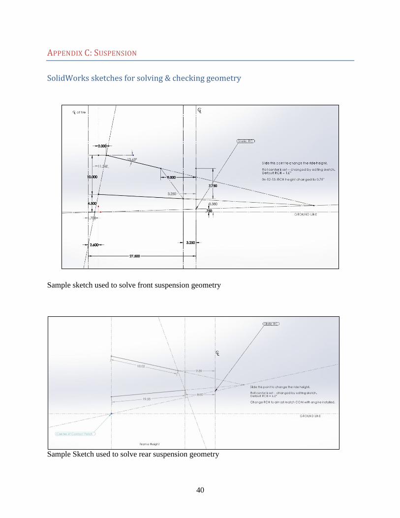
APPENDIX C: SUSPENSION
SolidWorks sketches for solving & checking geometry
Sample sketch used to solve front suspension geometry
Sample Sketch used to solve rear suspension geometry

41
Sample sketch used to check bell crank dimensions
42
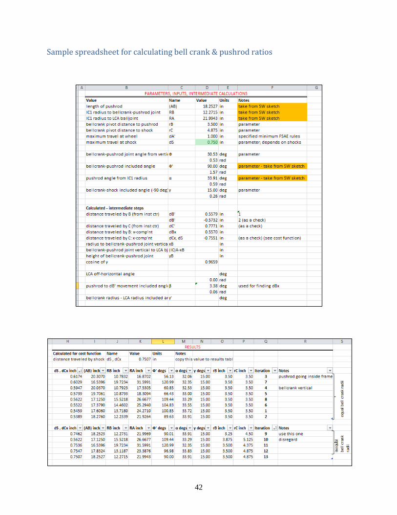
Sample spreadsheet for calculating bell crank & pushrod ratios

43
Sample Suspension Stress Analysis
SolidWorks Flow Analysis – FEA on Front Lower Control Arm, showing Von Mises stresses