Embed Size (px)
Citation preview
Ricomposizione motoreEngine reassembly
77
sezione / section
C
A
B
C
D
E
F
G
Scomposizione motoreEngine disassembly998RS03APERTURA CARTER
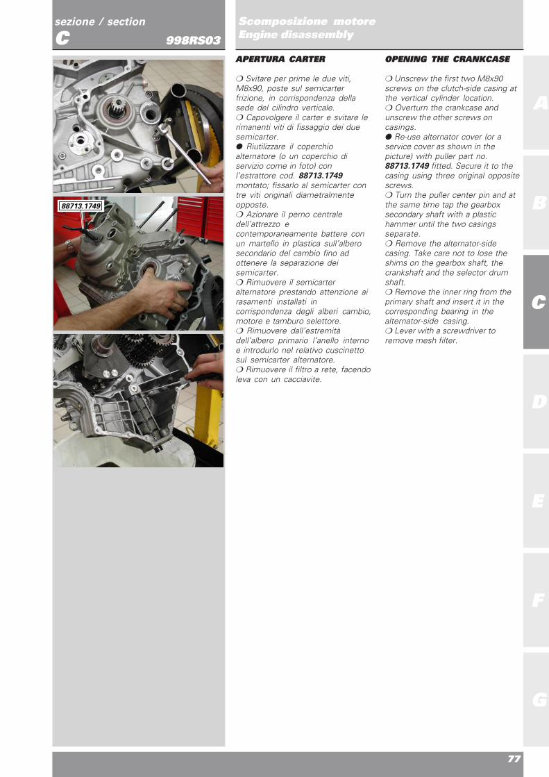
❍ Svitare per prime le due viti,M8x90, poste sul semicarterfrizione, in corrispondenza dellasede del cilindro verticale.❍ Capovolgere il carter e svitare lerimanenti viti di fissaggio dei duesemicarter.● Riutilizzare il coperchioalternatore (o un coperchio diservizio come in foto) conl’estrattore cod. 88713.1749montato; fissarlo al semicarter contre viti originali diametralmenteopposte.❍ Azionare il perno centraledell’attrezzo econtemporaneamente battere conun martello in plastica sull’alberosecondario del cambio fino adottenere la separazione deisemicarter.❍ Rimuovere il semicarteralternatore prestando attenzione airasamenti installati incorrispondenza degli alberi cambio,motore e tamburo selettore.❍ Rimuovere dall’estremitàdell’albero primario l’anello internoe introdurlo nel relativo cuscinettosul semicarter alternatore.❍ Rimuovere il filtro a rete, facendoleva con un cacciavite.
OPENING THE CRANKCASE
❍ Unscrew the first two M8x90screws on the clutch-side casing atthe vertical cylinder location.❍ Overturn the crankcase andunscrew the other screws oncasings.● Re-use alternator cover (or aservice cover as shown in thepicture) with puller part no.88713.1749 fitted. Secure it to thecasing using three original oppositescrews.❍ Turn the puller center pin and atthe same time tap the gearboxsecondary shaft with a plastichammer until the two casingsseparate.❍ Remove the alternator-sidecasing. Take care not to lose theshims on the gearbox shaft, thecrankshaft and the selector drumshaft.❍ Remove the inner ring from theprimary shaft and insert it in thecorresponding bearing in thealternator-side casing.❍ Lever with a screwdriver toremove mesh filter.
88713.1749

78
A
B
C
D
E
F
G
sezione / section
CScomposizione motoreEngine disassembly998RS03ELEMENTI INTERNISEMICARTER
❍ Sfilare l’albero motore dalsemicarter e recuperare il rasamentointerno.❍ Sfilare gli alberi di guida delleforcelle.❍ Spostare le forchette in modo dadisimpegnarle dalle cave deltamburo selettore ed estrarre iltamburo recuperando il relativorasamento.❍ Rimuovere le forcelle di innestodelle marce facendo attenzione alleboccole inserite nei perni di guida.❍ Rimuovere gli alberi primario esecondario del cambio completi diingranaggi e recuperare i relativirasamenti.
NotePer comodità di rimontaggio si
consiglia di lasciare l’anello internodel cuscinetto di estremitàsull’albero secondario montato suquest’ultimo.
❍ Rimuovere l’anello elasticosull’albero rinvio distribuzione, nellaparte esterna al semicarter frizione.❍ Sfilare l’albero rinvio distribuzionedal lato interno del semicarter.
CASINGS INNER PARTS
❍ Remove the crankshaft from thecasing. Keep the inner shim.❍ Slide out the fork guide rods.❍ Move the forks so that theydisengage from the grooves in theselector drum. Remove the drumand keep the shim.❍ Remove the gear selector forkstaking care not to lose the bushes inthe guide pins.❍ Remove the gearbox primary andsecondary shafts complete withgears and keep the shims.
NoteTo facilitate reassembly, leave
the inner ring of the end bearing onthe secondary shaft.
❍ Working on the outer side of theclutch-side casing, remove thecirclip from the timing layshaft.❍ Working from the inside of thecasing, remove the timing layshaft.

Ricomposizione motoreEngine reassembly
79
sezione / section
C
A
B
C
D
E
F
G
Scomposizione motoreEngine disassembly998RS03
❍ Rimuovere la levetta fermamarce (1) svitando la vite (2) difissaggio al semicarter. Recuperareil rasamento (3) e la molla (4).
❍ To remove the gear stop lever (1),unscrew the fixing bolt (2) fromcasing. Remove shim (3) and spring(4).
2 1
3 4
80
A
B
C
D
E
F
G
sezione / section
CScomposizione motoreEngine disassembly998RS03SCOMPOSIZIONE TESTE
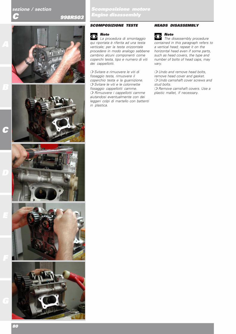
NoteLa procedura di smontaggio
qui riportata è riferita ad una testaverticale; per la testa orizzontaleprocedere in modo analogo sebbenecambino alcuni componenti comecoperchi testa, tipo e numero di vitidei cappellotti.
❍ Svitare e rimuovere le viti difissaggio testa, rimuovere ilcoperchio testa e la guarnizione.❍ Svitare le viti e le colonnettefissaggio cappellotti camme.❍ Rimuovere i cappellotti cammeaiutandosi eventualmente con deileggeri colpi di martello con battentiin plastica.
HEADS DISASSEMBLY
NoteThe disassembly procedure
contained in this paragraph refers toa vertical head; repeat it on thehorizontal head even if some parts,such as head covers, the type andnumber of bolts of head caps, mayvary.
❍ Undo and remove head bolts,remove head cover and gasket.❍ Undo camshaft cover screws andstud bolts.❍ Remove camshaft covers. Use aplastic mallet, if necessary.

Ricomposizione motoreEngine reassembly
81
sezione / section
C
A
B
C
D
E
F
G
Scomposizione motoreEngine disassembly998RS03
❍ Rimuovere gli alberi a camme.❍ Rimuovere i registri di apertura,avendo cura di riporre i registri diapertura, quelli di chiusura e levalvole in modo da non mescolarli.Ciò risulterà utile per richiudere ilmotore eventualmente si dovesseroriutilizzare gli stessi registri.❍ Rimuovere le viti di fissaggiocartelle lato cinghia.❍ Rimuovere la cartella latocinghia.
❍ Remove camshafts❍ Remove opening shims. Takecare not to make confusion betweenopening and closing shims andvalves. This proves useful in casethe same shims are used to closeengine.❍ Remove chain-side cover fixingscrews.❍ Remove chain-side cover.

82
A
B
C
D
E
F
G
sezione / section
CScomposizione motoreEngine disassembly998RS03
● Recuperare i tre OR (uno colorverde e due rossi) posti tra testa ecartella.❍ Svitare le viti di fissaggio dellacartella lato raccordo acqua.❍ Rimuovere la cartella latoraccordo acqua.● Preoccuparsi di recuperare gli OR(uno color verde e due rossi).❍ Per rimuovere i perni bilanciereusare l’attrezzo cod. 88713.1994;avvitare il perno filettatodell’attrezzo all’interno del pernobilanciere e, con un movimentorapido, tirare il battente dell’attrezzoin modo che l’urto del battentecontro il fine corsa provochi lafuoriuscita del perno bilanciere.
● Keep the three OR seals (one isgreen and two are red) betweenhead and cover.❍ Unscrew the coolant union sidecover fastening screws.❍ Remove coolant union side cover.● Keep the OR seals (one is greenand two are red).❍ Use tool part no. 88713.1994 toremove rocker arm shafts. Screwtool threaded pin inside rocker armshaft and, with a rapid movement,pull the tool beating face so that itsimpact against the limit stop willmake the rocker arm shaft come out.
88713.1994

Ricomposizione motoreEngine reassembly
83
sezione / section
C
A
B
C
D
E
F
G
Scomposizione motoreEngine disassembly998RS03
❍ Rimuovere completamente ilperno bilanciere, il bilanciere e lemolle di richiamo (nel caso deibilancieri di chiusura).❍ Per rimuovere il registro dichiusura ed i semiconi adoperarel’attrezzo cod. 041.1.056.1A,picchiando con un martello comeillustrato nell’immagine, oppurel’attrezzo cod. 041.1.055.1A.Infilare il bilanciere di apertura, senon è ancora stato rimosso, nellaferitoia ricavata nell’attrezzo stesso;appoggiare l’attrezzo al bordointerno della testa, quindi batterecon martello con battenti in plasticasulla sommità dell’attrezzo.
❍ Remove the complete rocker armshaft, the rocker arm and , forclosing rocker arms only, also thereturn springs.❍ Use tool part no. 041.1.056.1A toremove closing shim and valvecollets, tap with a hammer asindicated in the figure or use toolpart no. 041.1.055.1A.If not yet removed, position openingrocker arm in the tool slot; rest thetool on head inner edge, and tapwith a plastic hammer on top of thetool.
041.1.056.1A
041.1.055.1A

84
A
B
C
D
E
F
G
sezione / section
CScomposizione motoreEngine disassembly998RS03
NoteL’attrezzo è realizzato in modo
che la corsa venga arrestata dalbilanciere di chiusura onde evitareche urti il gommino o la testa,entrambi danneggiabili.
● Recuperare quindi i registri dichiusura ed i semiconi, evitando dimescolarli se si ha l’intenzione diriutilizzarli.❍ Sfilare le valvole.❍ Rimuovere i gommini di tenutavalvola aiutandosi con una pinza.
NoteThe tool is made in such a way
that the stroke stops against closingrocker arm to prevent damages torubber seal or cylinder head.
● Keep closing shims and collets. Ifthey have to be re-used, make surenot to mix them.❍ Remove valves.❍ Remove valve rubber seals withpincers.

Revisione motoreEngine overhaul
A
B
C
D
E
F
G
86
A
B
C
D
E
F
G
sezione / section
DRevisione motoreEngine overhaul998RS03
INDICE DI SEZIONE
PULIZIA DEI PARTICOLARI 88
ACCOPPIAMENTI 88
SOSTITUZIONE ANELLI DI TENUTAOLIO (PARAOLI) 89
ANELLI DI ARRESTO (SEEGER) 89
CUSCINETTI 90
CILINDRO 90Modalità di misura dell’alesaggio 90
PISTONE 91
SPINOTTO 91
SEGMENTI 92
ACCOPPIAMENTO SEGMENTO - CAVASUL PISTONE 92
ACCOPPIAMENTO SEGMENTI - CILINDRO 93
IMBIELLAGGIO 93
SCHEDA RILEVAMENTO DATI 94Biella 96Semicuscinetti 97Installazione cuscinetti 97 Big-end bearing - crankpin clearance 99Albero motore 98Accoppiamento semicuscinetti-perno biella 99Ricomposizione imbiellaggio 99
TESTA 101
SEDE VALVOLA 101
GUIDA VALVOLA 102
CONTROLLO TENUTA VALVOLE 103
CONTROLLO PROFONDITA’ VALVOLENELLA TESTA 103
VALVOLA 104
BILANCIERI 105
REGISTRI DI APERTURA E CHIUSURA - MOLLE 105
ALBERO A CAMME 106
PULEGGE - CINGHIE - TENDITORI 106
SEMICARTER MOTORE 107
CUSCINETTI DI BANCO 108
CIRCUITO DI LUBRIFICAZIONE 109
SCHEMA DI LUBRIFICAZIONE 110
POMPA OLIO 111
POMPA ACQUA 112
SECTION INDEX
CLEANING PARTS 88
CLEARANCES AND FITS 88
CHANGING OIL SEALS 89
CIRCLIPS 89
BEARINGS 90
CYLINDER 90Bore measuring procedure 90
PISTONS 91
GUDGEON PINS 91
PISTON RINGS 92
PISTON RING - PISTON GROOVE COULPING 92
PISTON RING - CYLINDER COUPLING 93
CONNECTING RODS 93
DATA RECORD SHEET 95Connecting rods 96Connecting rod bearings 97Assembling the bearings 97Crankshaft 98
Connecting rod reassembly 99
CYLINDER HEADS 101
VALVE SEATS 101
VALVE GUIDES 102
VALVE LEAK TEST 103
CHECKING THE VALVE POCKET DEPTH 103
VALVES 104
ROCKER ARMS 105
OPENING AND CLOSING SHIMS - SPRINGS 105
CAMSHAFT 106
ROLLERS - BELTS - TENSIONERS 106
CASINGS 107
MAIN BEARINGS 108
LUBRICATION CIRCUIT 109
LUBRICATION CIRCUIT DIAGRAM 110
OIL PUMP 111
WATER PUMP 112
Ricomposizione motoreEngine reassembly
87
sezione / section
D
A
B
C
D
E
F
G
Revisione motoreEngine overhaul998RS03
REVISIONE COMPONENTI FRIZIONE 113Campana 113Dischi 113Piatto spingidisco 114Molle 114Tamburo 114Flangia 114Molla antisaltellamento 114Anomalie frizione 115
GRUPPO DI RINVIO FRIZIONE 116
GRUPPO CAMBIO 117
TAMBURO COMANDO FORCHETTE 118
FORCHETTE SELEZIONE MARCE 118
SPESSORAZIONE ALBERI CAMBIO ETAMBURO COMANDO FORCELLE 119
CLUTCH OVERHAUL 113Clutch housing 113Clutch plates 113Pressure plate 114Springs 114Drum 114Flange 114Anti-slip spring 114Clutch troubleshooting 115
CLUTCH TRANSMISSION UNIT 116
GEARBOX 117
GEAR SELECTOR DRUM 118
GEAR SELECTOR FORKS 118
SHIMMING THE GEARBOX SHAFTS AND THEFORK SELECTOR DRUM 119

88
A
B
C
D
E
F
G
sezione / section
DRevisione motoreEngine overhaul998RS03PULIZIA DEI PARTICOLARI
Tutti i particolari metallici devonoessere puliti e lavati con solventespecifico, possibilmentebiodegradabile, ed asciugati conaria compressa.
AttenzioneDurante questa operazione si
sviluppano vapori infiammabili eparticelle di metallo possono essereespulse ad alta velocità. Siraccomanda di operare in unambiente privo di fiamme libere oscintille e di indossare protezioniadeguate.
Soffiare con aria compressa dentroai condotti di passaggio olio deisemicarter e delle teste. Togliereaccuratamente dalle superfici diaccoppiamento eventuali tracce disigillante, con estrema cautela, pernon danneggiarle: utilizzare a talfine raschietto e diluente specifico.Prima del rimontaggio, ripassare lefilettature di alloggiamento deiprigionieri nei semicarter e quelledelle viti, per eliminare i residui diLoctite o sigillante.
ACCOPPIAMENTI
Per consentire al motore difunzionare nelle migliori condizioni,fornendo quindi il massimorendimento, è indispensabile chetutti gli accoppiamenti rientrinonelle tolleranze prescritte dalla casacostruttrice.
CLEANING PARTS
All metal components must becleaned and washed using suitablebiodegradable solvents and thendried with compressed air.
WarningCleaning solvents give off
inflammable fumes. Metal particlesmay be projected at high speed fromengines during cleaning. Cleaningwith solvent must take place awayfrom naked flames or sparks. Alwayswear suitable protections duringcleaning operations.
Blow through the oilways in thecasings and the cylinder heads withcompressed air. Remove residues ofsealant from all contact andfastening surfaces. Do not damagethese surfaces. Use a suitablescraper and solvent. Beforereassembling the engine, clean alltraces of Loctite and sealant fromthe threads of the stud bolt holes inthe casings and of the screws.
CLEARANCES AND FITS
To ensure top engine performance,all the clearances and fits must bewithin the tolerances specified bythe manufacturer.

Ricomposizione motoreEngine reassembly
89
sezione / section
D
A
B
C
D
E
F
G
Revisione motoreEngine overhaul998RS03SOSTITUZIONE ANELLI DITENUTA OLIO (PARAOLI)
ImportanteSostituire sempre i paraolio ad
ogni revisione del motore. Installarei paraolio nuovi inserendolicorrettamente nei loro alloggiamentiutilizzando tamponi adatti. Montaresempre il paraolio con il latoprovvisto di molla rivolto verso ladirezione di uscita dell’olio (vedifigura). Durante il montaggio,lubrificare con olio motore i labbri ditenuta del paraolio.
CHANGING OIL SEALS
CautionChange oil seals at each
engine overhaul. Fit new oil sealsusing suitable drifts.Always fit oil seals with the springside facing the oil outfeed direction(see drawing).At reassembly, lubricate the seallips with a small amount of engineoil.
ANELLI DI ARRESTO (SEEGER)
ImportanteSostituire sempre gli anelli di
arresto che risultano deformati o chehanno perduto l’elasticità originale.Tutti gli anelli di arresto presentanoun lato (1) completamente pianocon spigolo vivo e un lato (2) aspigolo leggermente arrotondato.Quando si montano nelle gole deglialberi o nelle sedi dei coperchi, illato a spigolo vivo (1) deve sempreessere opposto alla direzione dellaforza (F) esercitata dall’elemento dafermare.
CIRCLIPS
CautionChange all circlips which are
deformed or which have lost theiroriginal spring.Circlips have a flat side (1) with asharp edge and a side (2) with aslightly rounded edge. Circlips mustbe fitted into shafts and coversgrooves with the sharp-edged side(1) always facing the force (F)applied by the part being held inposition.
Labbro primarioMain lip
Labbro secondarioSecondary lip
MollaSpring
SupportoSupport
OlioOil
2
1
1
2
F

90
A
B
C
D
E
F
G
sezione / section
DRevisione motoreEngine overhaul998RS03CUSCINETTI
ImportanteLavare accuratamente i
cuscinetti con benzina ed asciugarlicon aria compressa, senza farliruotare. Lubrificare leggermente eruotare lentamente a mano l’anellointerno: non si devono riscontrareirregolarità di rotazione, attritianomali o giochi eccessivi.
ImportanteSostituire i cuscinetti ad ogni
revisione del motore.
CILINDROControllare che la superficie discorrimento del pistone siaperfettamente liscia. Controllare lamisura dell’alesaggio.
Modalità di misuradell’alesaggioLa misura dell’alesaggio deveessere realizzata su 3 piani (1), (2)e (3) distanti dal piano testa -cilindro risp. 10, 40, 75 mm e lungodue direzioni: asse spinotto (A) easse perpendico-lare ad esso (B)(tot. sei misure). L’alesaggio siottiene come media delle sei misurecosì effettuate. perpendicolare allospinotto. L’alesaggio deve risultarecompreso tra 100,01 mm e 100,02mm.
BEARINGS
CautionWash bearings thoroughly
with fuel. Do not rotate bearingsduring washing. Dry withcompressed air.Lightly oil the bearings. Slowlyrotate the inner ring by hand andcheck for irregular rotation, jammingand excessive play.
CautionUse new bearings every time
engine is overhauled.
CYLINDERCheck that the walls are perfectlysmooth. Check bore size.
Bore measuring procedureBore shall be measured on threedifferent flat surfaces (1), (2) and (3)at a distance of 10, 40 and 75 mmrespectively from the cylinder-headand along two directions: gudgeonpin axis (A) and the axis (B)perpendicular to this one (sixreadings in total). Bore is theaverage value of the six readingstaken perpendicularly to thegudgeon pin. Bore should bebetween 100.01 and 100.02 mm.
Gioco assiale
Axial clearance
Gioco radiale
Radial clearance
10
1
2
3
40
75
A
B

Ricomposizione motoreEngine reassembly
91
sezione / section
D
A
B
C
D
E
F
G
Revisione motoreEngine overhaul998RS03PISTONE
Dopo aver rimosso i segmenti, pulireaccuratamente il cielo del pistone ele cave dei segmenti dalleincrostazioni carboniose. Procederead un accurato controllo visivo edimensionale del pistone: nondevono apparire tracce diforzamenti, rigature, crepe o altridanni.Misurare il diametro del pistone a4 mm dalla base del mantello, indirezione perpendicolare all’assedello spinotto. La misura del pistonedeve risultare compresa tra 99,925mm e 99,935 mm.Per determinare il gioco diaccoppiamento pistone cilindrobisogna confrontare la misura deldiametro del pistone con la mediadelle tre misure di diametro delcilindro effettuate nella direzioneortogonale all’asse spinotto.- Gioco di accoppiamento con il
cilindro:0,080 ÷ 0,090 mm.
SPINOTTO
Deve risultare perfettamentelappato, senza rigature, scalini ocolorazioni bluastre dovute aeccessivo riscaldamento. Lospinotto ben lubrificato deve poterscorrere all’interno della sede delpistone senza forzature.- Gioco di accoppiamento con
pistone:0 ÷ 0,018 mm
ImportanteSe le condizioni di usura non
permettono il riutilizzo dellospinotto, sostituirlo assieme alrelativo pistone.
PISTONS
Remove piston rings. Clean allcarbon deposits from the ringgrooves and the piston crowns.Thoroughly check pistons for wear ordamage. There must be no scoring,scuffing, cracks or visible damage.Measure the piston diameter at4 mm from the skirt base at rightangles to the axis of the gudgeonpin. Piston size should be between99.925 mm and 99.935 mm .Compare piston diameter with theaverage value of the three cylinderdiameters taken at right angles tothe gudgeon pin axis to determinecylinder-piston coupling clearance.- Cylinder coupling clearance:
0.080 - 0.090 mm.
GUDGEON PINS
Gudgeon pins must be smooth,without scoring, stepping or blueoverheating marks. A well lubricatedgudgeon pin must rotate smoothlyand easily in its seat.- Piston seat coupling clearance:
0 - 0.018 mm
CautionChange worn gudgeon pins.
Gudgeon pins are matched withpistons. If you change the gudgeonpin, you must also change thepiston.
4 m
m

92
A
B
C
D
E
F
G
sezione / section
DRevisione motoreEngine overhaul998RS03SEGMENTI
Non devono presentare tracce diforzamenti o rigature.
ImportanteSostituire sempre i segmenti
ad ogni revisione, consultando latabella degli intervalli dimanutenzione riportata all’inizio delmanuale.
NoteIl segmento superiore deve
essere montato con la “R” rivoltaverso l’alto.
ACCOPPIAMENTOSEGMENTO-CAVA SULPISTONE
La figura riporta il corretto giocoassiale che deve presentare ilsegmento nella relativa cava delpistone.- Gioco assiale segmento
superiore:0,03 ÷ 0,07 mm
- Gioco assiale raschiaolio:0,04 ÷ 0,12 mm
AttenzioneIn caso di sostituzione dei
segmenti, controllare sempre primadel montaggio il gioco assiale deisegmenti nuovi nel pistone.
PISTON RINGS
Piston rings must be free of scoring,scuffing and signs of forcing.
CautionChange piston rings at each
engine overhaul, respecting theintervals indicated in themaintenance schedule.
NoteUpper piston ring shall be
assembled with the “R” markingfacing up.
PISTON RING - PISTONGROOVE COULPING
The figure shows the correct axialplay of the piston rings inside thepiston grooves.- Upper piston ring axial play:
0.03 ÷ 0.07 mm- Scraper ring axial play:
0.04 ÷ 0.12 mm
WarningWhen changing piston rings,
always check their axial play insidepiston before assembly.
Ricomposizione motoreEngine reassembly
93
sezione / section
D
A
B
C
D
E
F
G
Revisione motoreEngine overhaul998RS03ACCOPPIAMENTO SEGMENTI-CILINDRO
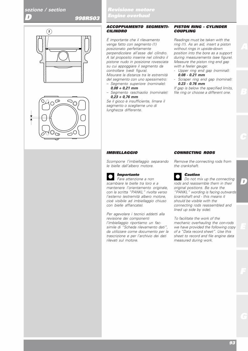
È importante che il rilevamentovenga fatto con segmento (1)posizionato perfettamenteperpendicolare all’asse del cilindro.A tal proposito inserire nel cilindro ilpistone nudo in posizione rovesciatasu cui appoggiare il segmento dacontrollare (vedi figura).Misurare la distanza tra le estremitàdel segmento con uno spessimetro:– Segmento superiore (nominale):
0,08 ÷ 0,21 mm– Segmento raschiaolio (nominale):
0,23 ÷ 0,76 mmSe il gioco è insufficiente, limare ilsegmento o sceglierne uno dilunghezza differente.
CONNECTING RODS
Remove the connecting rods fromthe crankshaft.
CautionDo not mix up the connecting
rods and reassemble them in theiroriginal positions. Be sure the“PANKL” wording is facing outwards(crankshaft end - this means itshould be visible with theconnecting rods reassembled andlined up side by side).
To facilitate the work of themechanic overhauling the con-rodswe have provided the following copyof a “Data record sheet”. Use thissheet to record and file engine datameasured during work.
IMBIELLAGGIO
Scomporre l’imbiellaggio separandole bielle dall’albero motore.
ImportanteFare attenzione a non
scambiare le bielle tra loro e amantenere l’orientamento originale,con la scritta “PANKL” rivolta versol’esterno (estremità albero motore,cioé visibile ad imbiellaggio chiusocon bielle affiancate).
Per agevolare i tecnici addetti allarevisione dei componentil’imbiellaggio riportiamo un fac-simile di “Scheda rilevamento dati”,da utilizzare come documento per latrascrizione e per l’archivio dei datirilevati sul motore.
PISTON RING - CYLINDERCOUPLING
Readings must be taken with thering (1). As an aid, insert a pistonwithout rings in upside-downposition into the bore as a supportduring measurements (see figure).Measure the piston ring end gapwith a feeler gauge:- Upper ring end gap (nominal):
0.08 - 0.21 mm- Scraper ring end gap (nominal):
0.23 - 0.76 mmIf gap is below the specified limits,file ring or choose a different one.
1

94
A
B
C
D
E
F
G
sezione / section
DRevisione motoreEngine overhaul998RS03
Fac-simile
SCHEDA RILEVAMENTO DATI
motore numero montaggio numero data
albero motore n° = km = Bielle km
Procedura di serraggio M10x1,25 1)Sgrassare superfici biella e viti con DET AT/AI CR2) Lubrificare vite e sottotesta con GREASE E3) Serrare per avvicinamento con allungamento di 0,050±0,005 mm4) Proseguire il serraggio fino alla lettura di un allungamento pari a 0,160±0,005 mm
campo tolleranza posizione valore misurato
perno di banco 34,975 ÷ 34,959 mm lato frizione (5)
lato alternatore (1)
perno di biella Selezione A: 42,006 ÷ 42,014 mm lato frizione (4)Selezione B: 41,998 ÷ 42,006 mm
centro (3)
lato alternatore (2)
diametro testa Selezione A: 46,021 ÷ 46,025 mm lato frizionedi biella Selezione B: 46,017 ÷ 46,021 mm
lato alternatore
diametro testa di lato frizione d25° = d0° = d25° = dm =biella con bronzine
lato alternatore d25° = d0° = d25° = dm =
accoppiamento 0,055 ÷ 0,065 mm lato frizionenominalebiella-perno di biella lato alternatore
numero numero posizione numero spessore o lunghezza lunghezza allung. coppia coppiabiella e serraggi viti serraggio selezione iniziale finale viti finale di dis-selezione biella viti bronzine viti viti serraggio serraggio
lato latofrizione numeroN°
latoselezione
lato latoalternatore numeroN°
latoselezione
2
1 5
3 4Lato
frizione
Lato
alternatore

Ricomposizione motoreEngine reassembly
95
sezione / section
D
A
B
C
D
E
F
G
Revisione motoreEngine overhaul998RS03
Facsimile
DATA RECORD SHEET
Engine number Assembly number Date
Crankshaft no. = km = Con-rods km
con-rod con-rod screw screw bear. shell screw screw screw final finaland class tightenings position tightenings thick. or initial final elong. tight. loos.number number number class length length torque torque
clutch numberside sideno.
classside
alternator numberside sideno.
classside
tolerance range position measured value
Main bearing 34.975 - 34.959 mm clutch side (5)
alternator side (1)
Crankpin Class A: 42.006 - 42.014 mm clutch side (4)Class B: 41.998 - 42.006 mm
center (3)
alternator side (2)
Con-rod big-end Class A: 46.021 - 46.025 mm clutch sidediameter Class B: 46.017 - 46.021 mm
alternator side
Con-rod big-end clutch side d25° = d0° = d25° = dm =diameter with bearingshells alternator side d25° = d0° = d25° = dm =
Con-rod - crank pin 0.055 - 0.065 mm clutch sidenominal coupling
alternator side
Tightening M10x1,25 1)Degrease con-rod and bolt surfaces using DET AT/AI CRprocedure 2) Lubricate screw and underside with GREASE E
3) Tighten for snugging with a stretch of 0.050±0.005 mm4) Continue tightening until reading a stretch of 0.160±0.005 mm
2
1 5
3 4Clutchside
Alternator
side
96
A
B
C
D
E
F
G
sezione / section
DRevisione motoreEngine overhaul998RS03
Proceed to connecting rods overhaulas follows:
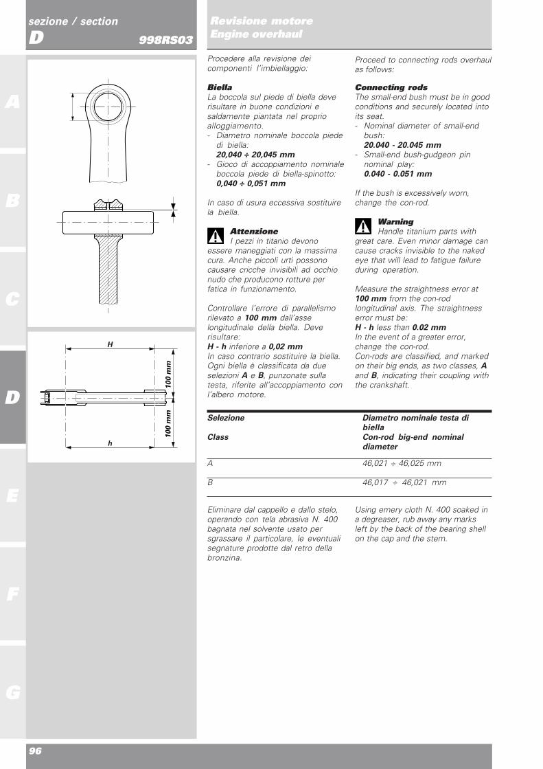
Connecting rodsThe small-end bush must be in goodconditions and securely located intoits seat.- Nominal diameter of small-end
bush:20.040 - 20.045 mm
- Small-end bush-gudgeon pinnominal play:0.040 - 0.051 mm
If the bush is excessively worn,change the con-rod.
WarningHandle titanium parts with
great care. Even minor damage cancause cracks invisible to the nakedeye that will lead to fatigue failureduring operation.
Measure the straightness error at100 mm from the con-rodlongitudinal axis. The straightnesserror must be:H - h less than 0.02 mmIn the event of a greater error,change the con-rod.Con-rods are classified, and markedon their big ends, as two classes, Aand B, indicating their coupling withthe crankshaft.
Using emery cloth N. 400 soaked ina degreaser, rub away any marksleft by the back of the bearing shellon the cap and the stem.
Procedere alla revisione deicomponenti l’imbiellaggio:
BiellaLa boccola sul piede di biella deverisultare in buone condizioni esaldamente piantata nel proprioalloggiamento.- Diametro nominale boccola piede
di biella:20,040 ÷ 20,045 mm
- Gioco di accoppiamento nominaleboccola piede di biella-spinotto:0,040 ÷ 0,051 mm
In caso di usura eccessiva sostituirela biella.
AttenzioneI pezzi in titanio devono
essere maneggiati con la massimacura. Anche piccoli urti possonocausare cricche invisibili ad occhionudo che producono rotture perfatica in funzionamento.
Controllare l’errore di parallelismorilevato a 100 mm dall’asselongitudinale della biella. Deverisultare:H - h inferiore a 0,02 mmIn caso contrario sostituire la biella.Ogni biella è classificata da dueselezioni A e B, punzonate sullatesta, riferite all’accoppiamento conl’albero motore.
Eliminare dal cappello e dallo stelo,operando con tela abrasiva N. 400bagnata nel solvente usato persgrassare il particolare, le eventualisegnature prodotte dal retro dellabronzina.
Selezione Diametro nominale testa dibiella
Class Con-rod big-end nominaldiameter
A 46,021 ÷ 46,025 mm
B 46,017 ÷ 46,021 mm
H
h
100 m
m100 m
m

Ricomposizione motoreEngine reassembly
97
sezione / section
D
A
B
C
D
E
F
G
Revisione motoreEngine overhaul998RS03
Colore Codice Dimensionenominale
Colors Code Nominal Size
Giallo112.1.019.1AA 1,976 ÷ 1,981Yellow
Verde112.1.019.1AB 1,980 ÷ 1,985Green
Marrone112.1.019.1AC 1,984 ÷ 1,989Brown
Nero112.1.019.1AD 1,988 ÷ 1,993Black
Blu112.1.019.1AE 1,992 ÷ 1,997Blue
SemicuscinettiÈ buona norma sostituire isemicuscinetti ad ogni revisione ocomunque secondo gli intervalliprescritti nella tabelle dellemanutenzioni periodiche riportatanella sezione B.I semicuscinetti nuovi vengonoforniti già pronti per il montaggio enon devono essere ritoccati conraschietti o tela smeriglio.Appartengono a cinque classidimensionali identificabile ciascunada un colore (GIALLO, VERDE,MARRONE, NERO, BLU).
Installazione cuscinettiI semicuscinetti, e quindi il loroalloggiamento nella testa di biella,sono dotati di un dentino per tenerliin posizione.
AttenzioneSia la biella sia il cappello
possiedono due cave molto simili; ildente della bronzina dovrà essereinserito nella cava più stretta delledue.
● Appoggiare il semicuscinettosulla testa o sul cappello di biella inmodo che la sporgenza delleestremità rispetto alla superficie diunione risulti equidistante.● Verificare anche che risulticentrato assialmente nella testa onel cappello di biella.● Con le dita spingere ilsemicuscinetto in sede facendopressione (F) sulla mezzeria delcuscinetto.● Eliminare eventuali bave chepossono formarsi nello sfregamentodell’estremità del cuscinetto con lospigolo della sede sulla biella.
AttenzioneVerificare che esista
comunque un po’ di gioco (A), tra ildente del semicuscinetto e il vanodel dente su bronzina (o sulcappello), onde evitare che il denteallontani il semicuscinetto dallabiella (o dal cappello).
Connecting rod bearingsChange the bearings every time theengine is overhauled or at regularintervals as specified in themaintenance schedule table ofSection B.Spare bearings are supplied readyfor fitting. They must not bereworked with scrapers or emerycloth.These bearings can belong to fivedifferent size classes identified bydifferent colors (YELLOW, GREEN,BROWN, BLACK, BLUE).
Assembling the bearingsBearings, as well as their locationinside con-rod big end, are providedwith a small tooth holding them inplace.
WarningBoth the con-rod and the con-
rod cap have two similar grooves;con-rod bearing tab should beinserted in the narrower groove.
● Put the bearing onto theconnecting rod big end or cap sothat an equal portion of bearingprotrudes over the big end on eitherside.● Make sure it is properly centeredwith the big end or cap axis.● Press onto the bearing axis (F)with your fingers and seat itproperly.● Remove any burrs due to bearingedge friction against the seat on thecon-rod.
WarningCheck that between bearing
tooth and tooth location on thebearing shell (or cap) there is someclearance (A) in order to avoid thatbearing is not moved away fromconnecting rod (or cap) by the tooth.
F
COLORECOLOR
A

98
A
B
C
D
E
F
G
sezione / section
DRevisione motoreEngine overhaul998RS03Albero motorePulire con estrema cura lecanalizzazioni olio interne all’albero,adoperando liquido sgrassante tipoDETA T / AL ed aria compressa.Procedere al controllo visivodell’albero motore: i perni di bancoe di biella non devono presentaresolchi o rigature. Eventualmentelevigare la superficie con telaabrasiva finissima e olio. Verificareche nella zona di raccordo tra pernoe spallamento non vi siano segni dilavoro o bave.- Raggio di raccordo:
2 mm
Le filettature, le sedi delle linguettee le scanalature devono essere inbuone condizioni.Rilevare la rettilineità e la circolaritàdel perno di biella.Per la rettilineità, effettuare tremisure su tre generatrici a 120° permetà della lunghezza del perno(valore nominale max. 0,005 mm).Per la circolarità effettuare tremisure sul piano di mezzeria e tre a90° da queste (valore nominale max.0,005 mm).Rilevare con comparatorel’allineamento dei perni di banco,posizionando l’albero motore tra duecontropunte:- Errore di allineamento nominale:
0,01 mmOgni albero motore è classificato dadue selezioni A e B, punzonate sulfianco mannaia, lato pignone,riferite al perno di biella.
CrankshaftThoroughly clean shaft oil innerducts with a degreaser such asDETA T / AL and blow withcompressed air.Visually inspect the crankshaft. Themain bearings and the crankpinsmust not be scored or grooved. Ifnecessary, polish the surface withfine emery cloth soaked in oil. Checkthat the area between the bearingand the shoulder is free from wear orburrs .- Radius:
2 mm
Check that the threads, keyways and splines are in good condition.Measure the straightness androundness of crank pin.Make three readings on threegenerating lines at 120° for half ofthe pin length (max. nominal value0.005 mm) to measure straightness.Make three readings on the centersurface and three at 90° from thefirst points (max. nominal value0.005 mm) to measure roundness.Fit the crankshaft between twocenters and then use a dial gauge tocheck the alignment of the mainbearings.- Nominal alignment error:
0.01 mmCrankshafts are classified in twotypes: A and B. The type is punchedon the side of the blade on thesprocket side close to the mainbearing.
Selezione Diametro nominaleType Nominal diameter
A 42,006 ÷ 42,014 mm
B 41,998 ÷ 42,006 mm
1
2
a b c
120˚
2 mm
Selezione
Type

Ricomposizione motoreEngine reassembly
99
sezione / section
D
A
B
C
D
E
F
G
Revisione motoreEngine overhaul998RS03
Ricomposizione imbiellaggio● Verificare che su ogni biella, tracappello e il relativo fusto, sianomontate le spine di centraggio.● Pulire accuratamente bielle e vitibielle con solvente sgrassante,adoperando degli scovolini in nylon.● Lubrificare con grasso prescritto ilfiletto e il sottotesta delle viti nuovee la sede filettata sul fusto,introducendo grasso dalle dueestremità del foro.
AttenzioneIl grasso utilizzato è irritante al
contatto con la pelle; indossareguanti protettivi.
Accoppiamentosemicuscinetti-perno biellaPer verificare il gioco diaccoppiamento tra semicuscinetti ealbero motore procedere comesegue:● Rilevare il diametro del perno dibiella in posizioni intermedie edequidistanti (a - b).In riferimento agli assi ortogonali(1 - 2), determinare il valore medio.▲ Serrare le viti della biella, allacoppia prescritta sezione B (senzasemicuscinetti).
ImportantePer svolgere le operazioni di
verifica del gioco di accoppiamentoè consigliato utilizzare delle viti dibiella di servizio, evitando così unulteriore serraggio delle viti da gara.Le viti da gara, infatti, possonosubire al massimo tre serraggi.
● Rilevare il diametro interno dellabiella, in riferimento agli assi (d - e - f)e determinare il valore medio.● Applicare la formula:SPESSORE SEMICUSCINETTO =(DIAMETRO BIELLA - DIAMETROPERNO - K) / 2
K = 0,041 mmGioco di accoppiamento nominale:0,060 ± 0,005 mm
Scegliere lo spessore dei semicusci-netti nella classe di appartenenza,che permetta la migliore centratura.
ImportanteEvitare di utilizzare imbiellaggi
che presentano un gioco inferiore a0,055 mm.
AttenzioneI pezzi in titanio devono essere
maneggiati con la massima cura.Anche piccoli urti possono causarecricche invisibili ad occhio nudo cheproducono rotture per fatica infunzionamento.
Big-end bearing - crankpinclearanceTo check the clearance between thebig-end bearings and the crankpinproceed as follows:● Measure the crankpin diameter inintermediate and equidistantpositions (a - b).Calculate the average value at rightangles (1 - 2).▲ Tighten the con-rod bolts to thespecified torque (Section B) (withoutbearings).
CautionTo check coupling clearance,
use service con-rod bolts in order toavoid one more tightening of racingbolts. Racing bolts can be used for atotal of three tihtenings only.
● Measure the internal diameter ofthe con-rod with reference to (d - e -f) axes. Calculate the average value.● Use the formula:BEARING THICKNESS = (CON-RODDIAMETER - CRANKPIN DIAMETER -K) / 2
K = 0.041 mmNominal clearance:0.060 - 0.005 mm
Select a bearing for proper centering(refer to bearing classes).
CautionDo not use bearings with
clearances of less than 0.055 mm.
WarningHandle the titanium parts with
great care. Even minor damage cancause cracks invisible to the nakedeye that will lead to fatigue failureduring operation.
Connecting rod reassembly● Check that centering pins arepositioned between the cap andshaft of all connecting rods.● Thoroughly clean all connectingrods and bolts with degreaser andnylon brushes.● Lubricate the new bolt undersideand the threaded hole on the shaftwith recommended grease. Fillgrease from both sides of the hole.
WarningCorrosion and irritant hazard.
The grease used is corrosive. Avoidcontact with skin and wearprotective gloves.
1
2
a b
45˚ 45˚
d
fe

100
A
B
C
D
E
F
G
sezione / section
DRevisione motoreEngine overhaul998RS03
ImportanteLa lubrificazione delle viti di
biella è fondamentale per ottenerel’accoppiamento prescritto edevitare la rottura dei componenti.Le viti di biella possono essereutilizzati solo per tre serraggi(compreso quello iniziale effettuatodal produttore).
▲ Avvitare a mano le viti fino inbattuta: se l’operazione risultadifficoltosa o si riscontranoimpuntamenti, svitare la vite elubrificarla nuovamente. Rimuoverel’eccesso di grasso.● Accostare a mano le due viti finoal contatto tra la testa vite e il pianod’appoggio sulla biella.● Interporre tra le bielle ildistanziale cod. 88713.1309 dispessore 2,35 mm ed eliminare ilgioco assiale residuo.▲ Montare provvisoriamente lospinotto tra i due piedi di bielleallineati, allineare le bielle, quindiprocedere al serraggio.● Per il corretto serraggio delle vitidi ciascuna biella sonoindispensabili: una chiavedinamometrica ed il micrometro conorologio comparatore e dotato dipuntale sferico di diametro 3 mm(cod. 88713.1781).● Azzerare il micrometro con orologiosu di una vite e serrarla con chiavedinamometrica fino a leggere unallungamento di 0,050 ± 0,005 mm.● Ripetere la stessa operazionesull’altra vite di biella.● Azzerare di nuovo il micrometrocon orologio sulla prima vite eserrarla con chiave dinamometricafino a leggere un allungamento di0,11 mm.● Ripetere la stessa operazionesull’altra vite di biella.● Per ogni vite l’allungamento totaledeve essere 0,160 ± 0,005 mm.
ImportanteNel maneggiare e
movimentare le bielle in titaniooccorre prestare la massimaattenzione ad evitare urti con corpiduri, che possono intaccare glispigoli della biella creando pericolosieffetti di intaglio. In particolar modosi deve assolutamente evitare l’urtodella costa della biella sui bordi delforo di montaggio dei cilindri sulcarter, durante tutte le operazioni dimontaggio/revisione nelle quali sitrascina a mano l’albero senza chesiano montati i gruppi cilindro -pistone. A tal fine si consiglia diutilizzare la flangia parabordi in teflon(cod. 041.1.029.1A) da infilare nel-l’ apertura carter onde evitare urtiche potrebbero danneggiare lebielle.
CautionCon-rod bolts lubrication is
critical for a correct coupling and toavoid parts breakage.Con-rod bolts may be used for atotal of 3 tightenings only (includingthe manufacturer’s originaltightening).
▲ Snug bolts by hand until drivingthem fully home: if this operationproves difficult, unscrew the bolt andgrease it again. Remove exceedinggrease.● Snug the two bolts by hand untilthe bolt head rests on the con-rodsurface.● Fit the 2.35 mm spacer part no.88713.1309 between con-rods totake up any axial play.▲ Temporarely fit crankpin betweenthe two aligned con-rod small ends,then align con-rods and proceed tobolt tightening.● For a correct bolt tightening, youmust use: a torque wrench and amicrometer with dial gauge and a 3mm ball pointer (part no.88713.1781).● Set dial gauge micrometer to zeroon one of the bolts, then tighten itwith the torque wrench until readinga stretch of 0.050 ± 0.005 mm.● Repeat procedure for the bolt onthe other connecting rod.● Set dial gauge micrometer to zeroagain on the first bolt and tighten itwith the torque wrench until readinga stretch of 0.11 mm.● Repeat procedure for the otherconnecting rod.● Total bolt stretch: 0.160 ± 0.005 mm.
CautionHandle titanium parts with
great care. Take care to avoidimpacts with hard bodies that coulddamage the con-rod edges and leadto dangerous notch effects. Avoidimpact of con-rod face with thecylinder hole edges for fitting oncasing during all the assembly/overhaul operations wherecrankshaft is turned by hand withoutthe cylinder-piston assemblies. Tothis end, to avoid possible impactsleading to connecting rod damages,the use of teflon bumper flange (partno. 041.1.029.1A) to be installedinto the casing opening is stronglyrecommended.

Ricomposizione motoreEngine reassembly
101
sezione / section
D
A
B
C
D
E
F
G
Revisione motoreEngine overhaul998RS03TESTA
Rimuovere i depositi carboniosidalla camera di combustione e dairelativi condotti. Pulire da eventualiincrostazioni le canalizzazioni delliquido di raffreddamento.Controllare che non vi siano crepe eche le superfici di tenuta risultinoprive di solchi, scalini o altreirregolarità.La planarità della superficie diaccoppiamento con il cilindro deveessere perfetta. In caso contrario,applicare su di un piano di riscontrosospensione diamantata (spessore6 ÷12 micron) e ripassare lasuperficie muovendo la testa comeevidenziato in figura, fino adottenere un piano uniforme.
CYLINDER HEADS
Remove carbon deposits fromcombustion chamber and ducts.Clean off scaling and deposits fromcoolant ducts. Check the head forcracks. Check that the contactsurfaces are smooth and without anyscoring, steps or damage.The contact surface with the cylindermust be perfectly flat. If this is notthe case, apply a grinding solution(6-12 micron thickness) to areference surface and grind thesurfaces by passing the head acrossthe table as shown in the drawing.Continue until you obtain a perfectlyflat surface.
SEDE VALVOLA
Controllare visivamente le sedi: nondevono presentare tracce divaiolature o incrinature.Riscontrando lievi danni è possibileeseguire una fresatura utilizzandoapposite frese monotaglienti:da 70° (fascia 1), 45° (fascia 2ASPIRAZIONE e SCARICO), 30°(fascia 3 ASPIRAZIONE eSCARICO).
In caso di danni eccessivi alle sedivalvola è possibile eseguirne lasostituzione utilizzando sedimaggiorate di 0,03 e 0,06 mm, suldiametro esterno, disponibili aricambio. Operare come segue:❍ Rimuovere le sedi usuratefresandole con cautela per nondanneggiare l’alloggiamento sullatesta;● Controllare il diametro deglialloggiamenti sulla testa e sceglierela sede valvola maggiorata piùidonea, considerando unainterferenza di montaggio di0,10÷0,15 mm;● Scaldare lentamente eduniformemente la testa fino ad unatemperatura di 150 °C e raffreddarele nuove sedi con ghiaccio secco;● Piantare le sedi perfettamente insquadro nel proprio alloggiamentoutilizzando gli appositi punzonicod. 88713.2206 (ASPIRAZIONE) ecod. 88713.2205 (SCARICO);● Lasciare raffreddare la testa equindi procedere alla lavorazionedelle sedi facendo riferimento allequote di figura.
VALVE SEATS
Visually check the condition of thevalve seats. There must be no signof pitting or cracking. Slight damagecan be removed using a single bladereamer of adequate size: 70° (radius1), 45° (radius 2 on both INTAKEand EXHAUST) and 30° (radius 3 onboth INTAKE and EXHAUST).
Badly damaged valve seats must beremoved and replaced withoversized seats. Fit new seats withouter diameters oversized by 0.03and 0.06 mm. Oversize seats areavailable as spare parts. To fit,proceed as follows:❍ Mill out the old seats taking carenot to damage the valve seatlocations.● Check the diameter of thelocations in the head and choose themost suitable oversizes seat takinginto account a negative allowanceof 0.10-0.15 mm.● Slowly and uniformly heat thehead to a temperature of 150°C.Cool the new seats with dry ice.● Drive the new seats squarely intotheir locations using the drifts partno. 88713.2206(INTAKE) and partno. 88713.2205 (EXHAUST).● Allow the head to cool down andthen machine the new seats as perthe measurements given in thedrawing.
DETT.X
FA
SC
IA 3
FA
SC
IA 3
SCA ASP
DETT.YFASC
IA1
FA
SCIA
1
Sgrossatura - Roughing

102
A
B
C
D
E
F
G
sezione / section
DRevisione motoreEngine overhaul998RS03
● Effettuare prima le lavorazioni disgrossatura e quindi quelle difinitura, come nelle figure allegate.
Dopo la lavorazione delle sedi èimportante verificare la tenuta travalvola e sede: se la superficie dicontatto sulla sede (S) dovesserisultare maggiore del tratto a 45°sulla valvola (W) si potrebberoverificare problemi di tenuta.
● Verificare la profondità dellevalvole nella testa come prescrittonel paragrafo dedicato.
GUIDAVALVOLA
Procedere al controllo dellecondizioni della superficie internadei guidavalvola: non devonoapparire incrinature o deformazioni.Sono disponibili a ricambioguidavalvola con maggiorazione suldiametro esterno di 0,03, 0,06 e0,09 mm.Per eseguire la sostituzione operarecome segue:● Riscaldare lentamente eduniformemente la testa fino allatemperatura di 150 °C;❍ Rimuovere i guidavalvolaoriginali utilizzando il punzonecod. 88713.2080.● Lasciare raffreddare la testa everificare le condizioni deglialloggiamenti dei guidavalvola;● Scegliere i guidavalvola piùidonei per ottenere una interferenzadi montaggio con la testa di0,022÷0,051 mm;● Riscaldare nuovamente la testa eraffreddare con ghiaccio secco iguidavalvole nuovi;
● You first have to rough and thenfinish valve seats, as shown in theattached figures.
When machining of the seats hasbeen completed, check the sealbetween valve and seat. If thecontact surface on the seat (S) isgreater than the 45° seating surfaceon the valve (W), this may causepoor sealing.
● Check valve pocket depth asdescribed in the relevant paragraph.
VALVE GUIDES
Check the condition of the innersurfaces of the valve guides. Theremust be no cracking or deformation.Spare valve guides are availablewith outer diameters oversized by0.03, 0.06 and 0.09 mm.To change valve guides, proceed asfollows:● Slowly and uniformly heat thehead up to a temperature of 150 °C;❍ Remove the original valve guidesusing drift part no. 88713.2080;● Allow the head to cool down andcheck the condition of the valveguide locations;● Select a suitable valve guidediameter allowing for aninterference fitting with head of0.022÷0.051 mm;● Heat the head again and cool thenew valve guides with dry ice;
DETT.V
SCA
EXH
ASP
INT
DETT.W
FASCIA
2
45˚
FA
SCIA
2
4
5˚
Finitura - Finishing
W
S45

Ricomposizione motoreEngine reassembly
103
sezione / section
D
A
B
C
D
E
F
G
Revisione motoreEngine overhaul998RS03
CONTROLLO TENUTAVALVOLE
La seguente procedura può avveniresia in sala prova che a motoremontato sul veicolo.● Portare a regime termico ilmotore (a circa 80° di olio e 70° diacqua), quindi spegnerlo.● Partire con il controllo del cilindroorizzontale.❍ Togliere la candela.● Inserire il connettoreMOTOMETER nel filetto candela(cod. 041.1.050.1A).● Aprire le farfalle al 100%.● Portare il motore a 1500 min-1
(nel caso di procedura sul veicolo,utilizzare avviatore ruota posteriore).● Leggere sullo strumento il valoredi compressione: se inferiore a 14bar (valore nominale 16±1 bar)ripristinare la tenuta valvole.● Ripetere la procedura sul cilindroverticale.
VALVE LEAK TEST
This test can be done either in a testroom or with the engine in theframe.● Let the engine warm up tooperating temperature (oil at about80° and water at 70°), then stop it.● Check the horizontal cylinder first.❍ Remove the spark plug.● Screw the MOTOMETERconnector into the spark plug thread(part no. 041.1.050.1A).● Open the throttles fully.● Crank the engine to 1,500 rpm (ifyou are doing the test with theengine in the frame, use the rearwheel starter).● Check the compression readingon the meter. In case the value isbelow 14 bar (16±1 bar nominalvalue), restore valve correct sealing.● Repeat the procedure with thevertical cylinder.
CONTROLLO PROFONDITÁVALVOLE NELLA TESTA
È possibile controllare la profonditàdelle valvole nella testa utilizzandogli attrezzi:cod.88765.1132 e cod.88765.1192per l’aspirazione;cod.88765.1131 e cod.88765.1193per lo scarico.● Inserire le valvole calibro88765.1192 in una sede valvoleaspirazione.● Appoggiare l’attrezzo cod.88765.1132 sulla testa rovesciata.● Con calibro di profondità inappog-gio sulla superficie esternaed inseri-to nelle apposite asoledell’attrezzo, controllare la valvola everificare la profondità.● Ripetere la stessa operazione perl’altra sede valvola aspirazione.● Ripetere le stesse operazioni perle sedi valvole di scaricoadoperando gli attrezzicod.88765.1131 e cod. 88765.1193.Deve risultare:Aspirazione 44,469±0,025 mmScarico 46,553±0,025 mm
● Lubrificare i fori ed installare iguidavalvola utilizzando gli appositiattrezzi:aspirazione cod. 88713.2203scarico cod. 88713.2204● Lavorare l’interno deiguidavalvole in modo da ottenere undiametro di Ø 6
+0,015+0,005
● Lubricate the valve guide bores inthe head using the following tools:intake valve guide drift: part no.88713.2203exhaust valve guide drift: part no.88713.2204● Ream valve guide inner part toreach a diameter of Ø 6
+0,015+0,005
CHECKING THE VALVEPOCKET DEPTH
The depth of valves on the headscan be checked using the followingtools:part no. 88765.1132 and part no.88765.1192 for intake valves;part no. 88765.1131 and part no.88765.1193 for exhaust valves.● Insert the master valves part no.88765.1192 in one of the intakevalve seats.● Rest tool part no. 88765.1132 onthe reversed head.● Rest a depth gauge on the outersurface and insert it through theslots in the service tool until ittouches the valve. Measure thedepth.● Repeat procedure for the otherintake valve seat.● Repeat procedure for the exhaustvalve seat with tools part no.88765.1131 and part no.88765.1193.Readings must be:Intake 44.469±0.025 mmExhaust 46.553±0.025 mm
SCA ASP

104
A
B
C
D
E
F
G
sezione / section
DRevisione motoreEngine overhaul998RS03VALVOLA
Controllare che lo stelo e lasuperficie di contatto con la sedevalvola siano in buone condizioni.Non devono apparire vaiolature,incrinature, deformazioni o tracce diusura. Misurare il diametro (A) dellazona di lavoro dello stelo, a diversealtezze deve risultare un diametrodi:- Aspirazione:
5,98 ÷ 5,99 mm- Scarico:
5,97 ÷ 5,98 mmmentre deve risultare un gioco dimontaggio tra valvola e guidavalvoladi:- Aspirazione:
0,006 ÷ 0,017 mm (nominale).- Scarico:
0,007 ÷ 0,018 mm (nominale).
Verificare la circolarità dellasuperficie a 45° della testa,sistemando un comparatore adangolo retto con la testa e ruotandola valvola in appoggio su di unriscontro a “V”:- Cilindricità nominale:
0,006 mm per lo Scarico0,006 mm per l’Aspirazione
Verificare mediante “blu di Prussia”o miscela di minio e olio, che lasuperficie di contatto (W) tra valvolae sede risulti completa, uniforme ecentrata sul tratto a 45° dellavalvola.
VALVES
The valve stems and valve matingsurfaces must be free of pitting,cracks, deformation or signs of wear.Measure the diameter (A) at variousheights in the stem working area.The diameter must be:- Intake valve:
5.98-5.99 mm- Exhaust valve:
5.97-5.98 mmwhile the assembly allowancesbetween valve stem and valve guideare:- Intake valve:
0.006-0.017 mm (nominal).- Exhaust valve:
0.007-0.018 mm (nominal).
Check the out-of-round of the 45°seating face. Rest the valve in a “V”reference block and use a dialgauge at right angles to the headwhile turning the valve in the block.- Nominal out-of-round:
0.006 mm for Exhaust valve0.006 mm for Intake valve
Use “Prussian blue” or a mixture ofminium and oil and check that thecontact surface (W) between thevalve and the valve seat iscomplete, uniform and centered onthe 45° valve seating face.
A
45
W

Ricomposizione motoreEngine reassembly
105
sezione / section
D
A
B
C
D
E
F
G
Revisione motoreEngine overhaul998RS03BILANCIERI
Controllare che le superfici di lavorosiano in perfette condizioni, senzatracce di usura, solchi o distacchidel riporto di cromo. Controllare lecondizioni del foro del bilanciere equelle del relativo perno.Gioco di accoppiamento almontaggio:0,030 ÷ 0,061 mm.Pulire i canali di passaggio olio neiperni bilanciere con scovolino e ariacompressa.
ROCKER ARMS
Check that the work surfaces of therocker arms are in good condition,without any signs of wear, scoring orpeeling of the chrome coating.Check the condition of the hole inthe rocker arm and the shaft.Assembly clearance:0.030 - 0.061 mm.Clean the oilways in the rocker armshafts using a pipe cleaner brushand compressed air.
REGISTRI DI APERTURA ECHIUSURA - MOLLE
Verificare le condizioni dellesuperfici di lavoro dei registri dichiusura e apertura delle valvole:non devono presentare tracce diusura.Verificare le condizioni delle molledi richiamo dei bilancieri dichiusura: non devono presentareincrinature, deformazioni ocedimenti.
OPENING AND CLOSINGSHIMS - SPRINGS
Check the work surfaces of the valveopening and closing shims. Theremust be no signs of wear.Check the closing rocker arm returnsprings. The springs must not becracked, bent or show signs offailure.

106
A
B
C
D
E
F
G
sezione / section
DRevisione motoreEngine overhaul998RS03ALBERO A CAMME
Controllare che le superfici di lavorodelle camme siano prive di striature,solchi, scalini o ondulazioni. Lecamme troppo usurate sono spessocausa di una irregolare fasatura cheriduce la potenza del motore.
AttenzioneManipolare con estrema cura,
l’albero a cammes. Eventuali graffi oanche impercettibili ammaccaturedovute ad urti, cadute dal banco,ecc... possono infatti pregiudicare ilrendimento del motore.
Controllare che i passaggi olio nonsiano ostruiti; pulire accuratamentecon liquido sgrassante ed ariacompressa.
CAMSHAFT
Check that the work surfaces of thecams are free of scratches, grooves,steps and waving. Worn cams areoften the cause of irregular timingand cause power losses.
WarningHandle the camshafts with
great care. Possible dents,scratching caused by shocks, fallsfrom the bench and so on may affectoperation and lead to severe enginedamage.
Check that inner oil ducts are notobstructed; thoroughly clean withdegreaser and blow withcompressed air.
PULEGGE - CINGHIE -TENDITORI
Le pulegge della distribuzione nondevono presentare tracce di usura oaltre irregolarità.Ad ogni rimontaggio sostituiresempre la ghiera di bloccaggiopuleggia.
NoteControllare la sede linguetta
all’interno della flangia puleggia: nondeve presentare segni di usura e/oessere impostata.
Le cinghie devono essere in perfettecondizioni, senza screpolature, taglio deformazioni.
ImportanteÈ buona norma sostituire le
cinghie ad ogni revisione delmotore.
ROLLERS - BELTS -TENSIONERS
Belt rollers must not show any signsof wear or damage of any kind.Change the belt roller locking ringnut at every reassembly.
NoteCheck the keyway inside the
belt roller flange: it must not beworn and/or show signs of driving.
Belts must be in perfect condition:without cracks, cuts or kinks.
CautionIt is good working practice to
change the belts at each engineoverhaul.
Mobile - Mobile
Fisso - Fixed

Ricomposizione motoreEngine reassembly
107
sezione / section
D
A
B
C
D
E
F
G
Revisione motoreEngine overhaul998RS03
Ruotando la bussola esterna deitenditori, verificare lo stato di usuradel cuscinetto interno. Sostituire iltenditore che presenti difficoltà dirotazione o gioco eccessivo.
Turn the outer bush of the tensionersand check the wear of the innerbearing. If the bearing rotates withdifficulty or shows excessive play,change the tensioner.
SEMICARTER MOTORE
Eliminare ogni traccia di sigillante.Lavare accuratamente tutte lecanalizzazioni interne, eliminandoeventuali strozzature od ostruzioni;asciugare con aria compressa quindiprocedere ad un accurato controllovisivo dei semicarter.Controllare, su di un piano diriscontro, che le superfici diaccoppiamento siano perfettamentepiane. In caso contrario, applicaresospensione diamantata (spessore6÷12 micron) e ripassare lasuperficie nel modo descritto alcapitolo “Testa”.Controllare che i cuscinetti siano inottimo stato. In caso di sostituzione,seguire la procedura descritta alcapitolo “Cuscinetti di banco”.
CASINGS
Clean off all signs of sealant.Thoroughly wash and clean all innerducts removing any blockages orobstructions and then dry withcompressed air.Visually check the casing.Place the casing on a referencesurface and check that the matingsurfaces are perfectly flat. If thesurfaces are uneven, grind themwith a grinding solution (6-12micron) as described in “CylinderHead”.Check that the bearings are in goodcondition. To change the bearings,follow the instructions given in“Main bearings”.
Mobile
Mobile
Fisso
Fixed

108
A
B
C
D
E
F
G
sezione / section
DRevisione motoreEngine overhaul998RS03CUSCINETTI DI BANCO
NoteI cuscinetti di banco devono
sempre essere sostituiti in coppia edevono essere installati nel giustoverso nelle rispettive bussole deisemicarter. Osservando il cuscinettoriconoscere il lato (1) in cui lo spes-sore (S) dell’anello esterno risultaminore. Il cuscinetto dovrà esseremontato nella relativa bussola mante-nendo il lato (1) all’esterno. Infatti,quest’ultimo, sarà il lato che andrà poiin appoggio sull’albero motore.
Per sostituire i cuscinetti ènecessario:● Riscaldare il semicarter in fornoalla temperatura di 100°C;❍ Rimuovere il cuscinetto originalemediante tampone e martello;▲ Installare il nuovo cuscinetto(mentre il semicarter è ancora adalta temperatura) perfettamente insquadro con l’asse dell’alloggiamen-to, utilizzando un tampone tubolareche eserciti la pressione solosull’anello esterno del cuscinetto;● Lasciare raffreddare il semicartered accertarsi che il cuscinetto risultisaldamente fissato nella relativabussola.Dopo aver installato i cuscinetti dibanco nuovi applicare la seguenteformula per determinare la quota“S” totale delle spessorazioni:• S = P1+P2–l+PmtDove:P1 = profondità carter lato frizione,P2 = profondità carter lato catena,l = larghezza tra le superfici diappoggio dell’anello interno deicuscinetti sull’albero motorePmt = precarico medio teorico(0,15 mm).Considerando l’allineamentodell’albero, è necessario conoscerel’entità delle singole spessorazioni“S1” e “S2”.• S1 = P1 +• S2 = S–S1Dove:S1 = spessorazione lato frizioneS2 = spessorazione lato catenaSono disponibili a ricambio rasamentidi spessore da 1,9 a 2,55 mm adintervalli di 0,05 mm. Una voltachiuso il carter, inserire tra le biellel’attrezzo speciale cod.88713.1309per annullare il gioco assiale emisurare. Verificare che la distanza trail piano esterno del piede di biella(foro piccolo) e la generatrice esternadel centraggio (diametro del cilindro)sia la stessa tra i due cilindri a menodella tolleranza ± 0,1 mm. In casocontrario suddividere adeguatamen-te lo spessore totale, senza cambiaretale valore, tra lato frizione e latocatena e ripetere il controllo.
MAIN BEARINGS
NoteMain bearings must always be
changed in pairs and must be fittedin the right direction in therespective casing bushes. Inspectthe bearing to establish the side (1)where the thickness (S) of the outerring is lower. The bearing must befitted in the corresponding bush,keeping the side (1) on the outside.This is the side which will contactthe crankshaft.
To change the bearings, proceed asfollows:● Heat the casing in an oven to100°C.❍ Remove the old bearing using adrift and a hammer.▲ While the casing is still hot, fit thenew bearing squarely into its seat.Use a tubular drift and ensure thatyou only exert pressure on the outerbearing ring.● Allow the casing to cool down andthen check that the bearing issecurely fixed into its bush.After fitting the new main bearings,calculate the total shimming “S”required using the following formula:• S = P1+P2–l+PmtWhere:P1 = clutch-side casing depthP2 = chain-side casing depthl = distance between the contactsurfaces of the inner ring of thecrankshaft bearings.Pmt = average theoretical preload(0.15 mm).To align the crankshaft it will benecessary to know the size of theshims “S1” and “S2”.Calculate these as follows:• S1 = P1+
• S2 = S–S1
Where:S1 = clutch-side shimmingS2 = chain-side shimmingSpare sets of shims are availablewith shims from 1.9 to 2.55 mm insteps of 0.05 mm. Once casingshave been closed, fit special toolpart no. 88713.1309 betweenconnecting rods in order to take upany axial play. Then take a reading.Check that the distance between theouter side of the con-rod small end(small hole) and the outer centeringgenerating line (cylinder diameter)is the same between the twocylinders, with a tolerance of ± 0.1mm. If this is not the case, dividethe total thickness, but keep itunchanged, between the clutch sideand chain side. Then repeat check.
l2
-2
Pmt
l2
-2
PmtP1
S1
P2
S2
Lato frizione
Clutchside
Lato alternatore
Alternatorside
I
Pia
no
co
nta
tto
sem
icart
er
Cra
nkcase c
on
tact
su
rface
1
S
1
S

Ricomposizione motoreEngine reassembly
109
sezione / section
D
A
B
C
D
E
F
G
Revisione motoreEngine overhaul998RS03CIRCUITO DI LUBRIFICAZIONE
l circuito di lubrificazione del motorecomprende:- Coppa olio- Filtro a rete- Pompa olio con valvola limitatrice
di pressione (by pass)- Radiatore- Filtro a cartuccia.
La pompa olio è del tipo adingranaggi con valvola by passincorporata e prende il moto, tramiteuna coppia dentata, dall’alberomotore. La sua portata è quindifunzione del regime di rotazione delmotore.L’olio viene prelevato con un filtro arete, in grado di trattenere eventualiimpurità grossolane, l’olioraggiunge la pompa. Al suo internoagisce una valvola limitatrice cherimanda l’eccedenza di olio inaspirazione in caso di pressioneeccessiva.Dalla pompa, l’olio va verso ilradiatore attraverso un tuboflessibile e attraversa il radiatoreraffreddandosi e successivamenteraggiunge il filtro a cartucciaall’uscita del quale segue quattrocircuiti:- il primo, attraverso un particolare
getto, raffredda il cielo del pistoneorizzontale;
- il secondo, passando attraversouna vite forata nel semicarteralternatore, raffredda il cielo delpistone verticale;
- il terzo, passando attraverso uncondotto del coperchio frizione,porta l’olio all’albero motore.
- il quarto si dirama dal pozzetto dialimentazione dell’albero motoree, attraverso due tubi flessibili,raggiunge le due teste; dopo averlubrificato gli elementi delladistribuzione l’olio ricade nelbasamento attraverso i cilindri.
L’olio, passando in canali interniall’albero motore, lubrifica isemicuscinetti della testa di biella.Una volta uscito dal circuito inpressione e lubrificati gli organidescritti, nel ricadere nelbasamento, lubrifica la trasmissioneprimaria, il cambio ed i cuscinetti disupporto degli alberi cambio.Il circuito di sfiato dei vapori chevengono a crearsi all’interno delbasamento comprende una valvolalamellare posta alla fine di uncondotto, prima dell’air box. Inquesto modo, il lungo percorso,permette ai vapori di olio diricondensare e ritornare nelbasamento.
LUBRICATION CIRCUIT
Engine lubrication circuit includes:- Oil sump- Mesh filter- Oil pump with pressure reducing
(by-pass) valve- Oil cooler- Cartridge filter.
The oil pump is a gear type pumpincorporating a by-pass valve. Thepump is driven over a toothed gearpair by the crankshaft. Pump flowrate therefore depends on enginespeed.The oil is picked up by a mesh filterwhich holds back large impuritiesand is fed to the pump. Inside thepump a by-pass valve returns anyexcess oil caused by excessivepressure to the intake end.The oil flows, into a hose, from thepump to the oil cooler. The oil iscooled down and then reaches thecartridge filter, where it divides intofour circuits:- the first circuit feeds oil to a jet
which cools the horizontal pistoncrown;
- the second circuit passes througha drilled screw in the alternatorcasing and cools the verticalpiston crown;
- the third circuit passes through aduct in the clutch cover and feedsthe oil to the crankshaft.
- the fourth circuit, starting from thecrankshaft feeding recess andpassing through the hoses,reaches the two heads; then itlubricates the timing elementsand drops down into thecrankcase through the cylinders.
The oil passes through the oilways inthe crankshaft and lubricates con-rod big-end bearings.After lubricating the parts described,the oil leaves the pressurised circuitand drops down into the crankcasewhere it lubricates the primary drivegears, the gearbox and the gearboxshaft bearings.The oil breather pipe for the oilfumes created inside the crankcasehas a reed valve positioned justbefore the air box. Given the lengthof the breather circuit, the oil fumescondense in the breather pipe andreturn to the crankcase.
110
A
B
C
D
E
F
G
sezione / section
DRevisione motoreEngine overhaul998RS03
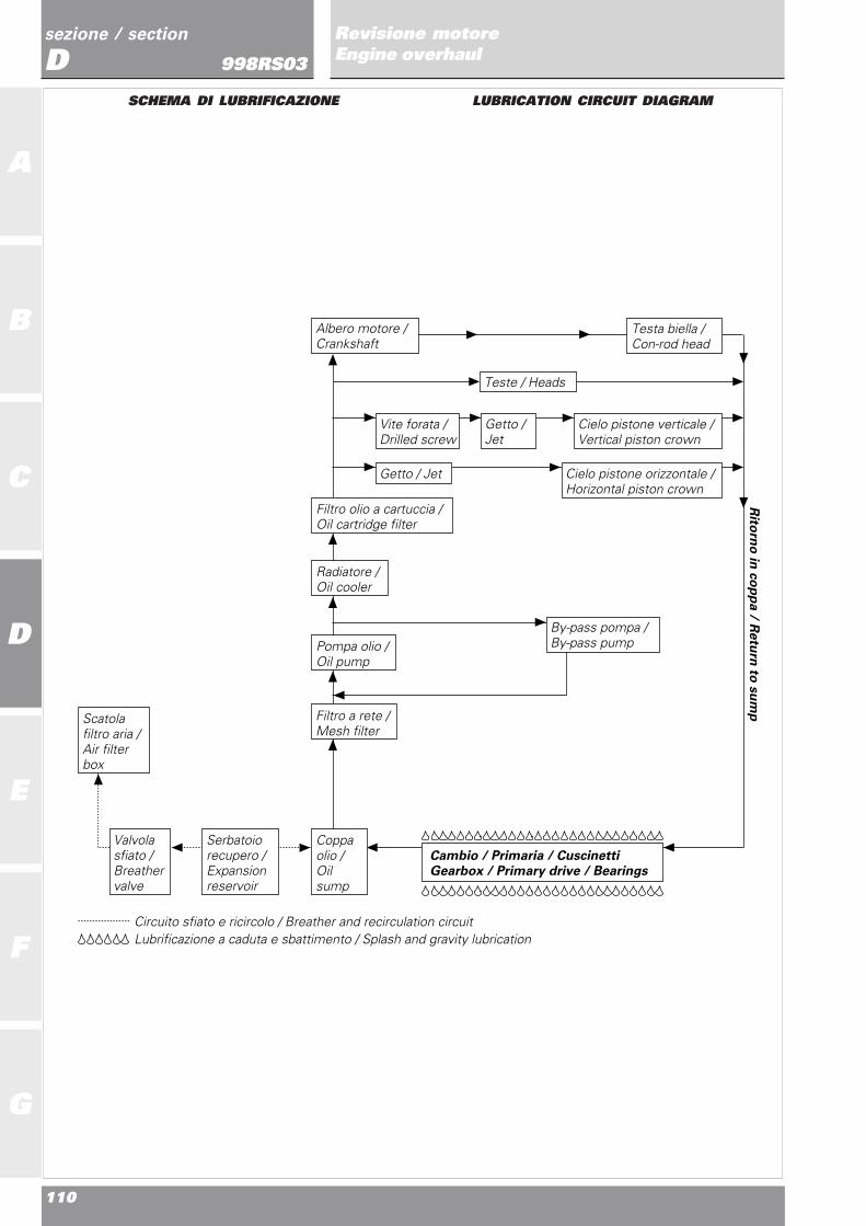
SCHEMA DI LUBRIFICAZIONE LUBRICATION CIRCUIT DIAGRAM
Scatola filtro aria /Air filter box
Circuito sfiato e ricircolo / Breather and recirculation circuitLubrificazione a caduta e sbattimento / Splash and gravity lubrication
Coppa olio /Oil sump
Valvola sfiato /Breather valve
Serbatoiorecupero /Expansionreservoir
Filtro olio a cartuccia / Oil cartridge filter
Albero motore /Crankshaft
Teste / Heads
Cielo pistone verticale /Vertical piston crown
By-pass pompa / By-pass pump
Vite forata /Drilled screw
Getto / Jet
Cielo pistone orizzontale /Horizontal piston crown
Getto / Jet
Pompa olio /Oil pump
Radiatore /Oil cooler
Filtro a rete / Mesh filter
Rito
rno
in c
op
pa / R
etu
rn to
su
mp
Testa biella /Con-rod head
Cambio / Primaria / Cuscinetti Gearbox / Primary drive / Bearings

Ricomposizione motoreEngine reassembly
111
sezione / section
D
A
B
C
D
E
F
G
Revisione motoreEngine overhaul998RS03POMPA OLIO
Una volta aperta, procedere aiseguenti controlli:- gioco tra i denti degli ingranaggi:
limite di servizio 0,10 mm- gioco radiale tra ingranaggi e
corpo pompa:limite di servizio 0,10 mm
- gioco assiale tra ingranaggi ecoperchio:limite di servizio 0,07 mm.
Verificare inoltre le condizioni dellesuperfici di accoppiamento sulcoperchio e sul corpo pompa: nondevono presentare solchi, scalini origature.Rimuovere dal coperchio il tappo(1), sfilare la molla (2) e la valvolaby pass (3). Verificare le lorocondizioni.Lavare e soffiare con aria compressai canali interni.Una volta riassemblata, riempire lapompa con olio motore prima delrimontaggio.
OIL PUMP
Open the pump and check thefollowing:- clearance between the gear
teeth:service limit 0.10 mm
- radial clearance between gearsand pump body:service limit 0.10 mm
- axial clearance between gearsand pump cover:service limit 0.07 mm.
Check the condition of the contactsurfaces on the cover and on thepump body. These surfaces must befree of scoring, stepping andgrooving.Remove the cover plug (1), slide outthe spring (2) and the by-passvalve (3). Check the condition ofthese parts.Wash out the oilways and blowthrough with compressed air.Reassemble the pump. Fill thepump with engine oil before refittingit to the engine.
32
1

112
A
B
C
D
E
F
G
sezione / section
DRevisione motoreEngine overhaul998RS03POMPA ACQUA
Pulire le canalizzazioni delcoperchio lato catena da eventualiincrostazioni del liquido refrigerante.Verificare lo stato di usura deicuscinetti ruotando lentamente lagirante; in caso di gioco eccessivo ènecessario rimuoverli operandocome indicato nella scomposizionemotore.Verificare le condizioni deicomponenti della tenuta meccanica:non devono apparire deformazioni,incrinature o usura eccessiva. Incaso di danni, è necessariosostituire entrambi i componenti.
WATER PUMP
Clean any coolant deposits from theducts in the chain-side cover. Turnthe pump rotor slowly to check forplay in the pump bearings. If there isexcessive play, remove and changethem as described in “EngineDisassembly”.Check the condition of themechanical seals; check for cracks,excessive wear and deformation.Change damaged seals. Seals mustbe changed in pairs.

Ricomposizione motoreEngine reassembly
113
sezione / section
D
A
B
C
D
E
F
G
Revisione motoreEngine overhaul998RS03REVISIONE COMPONENTIFRIZIONE
Campana● Inserire il disco conduttore (1)nella campana (2) e misurare conspessimetro il gioco esistente S.- Deve risultare:
S non superiore a 0,6 mm.In caso contrario sostituire i dischied eventualmente la campana.Verificare se la campana presentacricche o evidenti segni diimpostazione nel punto di appoggiodei dischi conduttori.
DischiI dischi non devono presentaretracce di bruciature, solchi odeformazioni. Appoggiare il disco suun piano di riscontro e controllarecon uno spessimetro l’entità delladeformazione:- Errore max. di planarità:
0,2 mm.Per verificare l’usura dei dischiconduttori è necessario misurare ilpacco composto da n° 9 dischisinterizzati.
Se il loro spessore è maggiore ouguale a 22 mm montare:- 4 dischi condotti spessore 1,5
mm1 disco condotto spessore 2 mm4 dischi bombati9 dischi sinterizzati
(per l’ordine fare riferimento alparagrafo “Ricomposizionecoperchio frizione e frizione” nellasezione “Ricomposizione motore”).- Se risulta inferiore a 22 mm:
installare un disco da 2 mm (indotazione) in luogo di uno da 1,5mm
- Se risulta inferiore a 21,5 mm:installare n° 2 dischi da 2 mm (indotazione) in luogo di due da 1,5mm
- Se risulta inferiore a 21 mm:sostituire il pacco dischi.
A corredo vengono forniti n° 4 dischidi spessore 2 mm per effettuare laregistrazione del pacco.
CLUTCH OVERHAUL
Clutch housing● Insert the driving plate (1) in theclutch housing (2) and use a feelergauge to measure the clearance S.- Clearance :
S not greater than 0.6 mm.If the clearance is greater than this,change the plates and the clutchhousing.Check the clutch housing for cracksand heavy marking where the drivingplates rest against the clutchhousing.
Clutch platesCheck the plates for burning,grooves and deformation. Place theplate on a reference surface andcheck the amount of deformationwith a feeler gauge:- Max. flatness error:
0.2 mm.To check the wear of the drivingplates, measure the thickness of apack of 9 plates.
If the pack thickness is higher thanor equal to 22 mm, fit:- 4 driven plates 1.5 mm thick
1 driven plate 2 mm thick4 convex plates9 sintered plates
(for correct order, refer to “Clutchand clutch cover reassembly” undersection “Engine reassembly”).- If the pack is less than 22 mm
thick: fit a 2 mm-thick plate(supplied) in place of the 1.5mm plate.
- If the pack is less than 21.5 mmthick: fit two 2 mm-thick plates(supplied) in place of the two 1.5
mm plates- If the pack is less than 21 mm
thick: change the plate pack.A kit containing four 2 mm plates foradjusting the pack thickness issupplied.
Pacco sinterizzati N°dischi condotti da 2 mmSintered plate pack No. of 2 mm thick driven plates
Più di 22 mm1More than 22 mm
Tra 21,5 mm e 22 mm2Between 21.5 mm and 22 mm
Tra 21 mm e 21,5 mm3Between 21 mm and 21.5 mm
Meno di 21 mm Sostituire dischi sinterizzatiLess than 21 mm Replace sintered plates
S
2
1
114
A
B
C
D
E
F
G
sezione / section
DRevisione motoreEngine overhaul998RS03
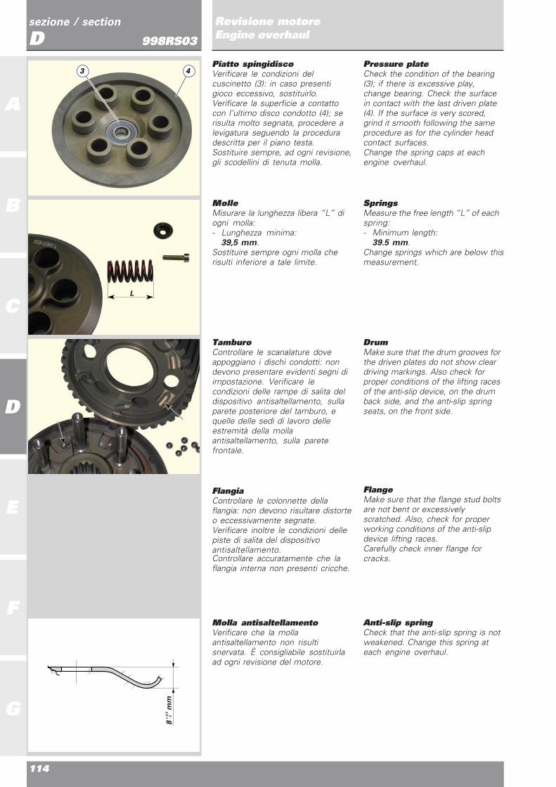
MolleMisurare la lunghezza libera “L” diogni molla:- Lunghezza minima:
39,5 mm.Sostituire sempre ogni molla cherisulti inferiore a tale limite.
SpringsMeasure the free length “L” of eachspring:- Minimum length:
39.5 mm.Change springs which are below thismeasurement.
TamburoControllare le scanalature doveappoggiano i dischi condotti: nondevono presentare evidenti segni diimpostazione. Verificare lecondizioni delle rampe di salita deldispositivo antisaltellamento, sullaparete posteriore del tamburo, equelle delle sedi di lavoro delleestremità della mollaantisaltellamento, sulla paretefrontale.
FlangiaControllare le colonnette dellaflangia: non devono risultare distorteo eccessivamente segnate.Verificare inoltre le condizioni dellepiste di salita del dispositivoantisaltellamento.Controllare accuratamente che laflangia interna non presenti cricche.
DrumMake sure that the drum grooves forthe driven plates do not show cleardriving markings. Also check forproper conditions of the lifting racesof the anti-slip device, on the drumback side, and the anti-slip springseats, on the front side.
FlangeMake sure that the flange stud boltsare not bent or excessivelyscratched. Also, check for properworking conditions of the anti-slipdevice lifting races.Carefully check inner flange forcracks.
Molla antisaltellamentoVerificare che la mollaantisaltellamento non risultisnervata. È consigliabile sostituirlaad ogni revisione del motore.
Anti-slip springCheck that the anti-slip spring is notweakened. Change this spring ateach engine overhaul.
Piatto spingidiscoVerificare le condizioni delcuscinetto (3): in caso presentigioco eccessivo, sostituirlo.Verificare la superficie a contattocon l’ultimo disco condotto (4); serisulta molto segnata, procedere alevigatura seguendo la proceduradescritta per il piano testa.Sostituire sempre, ad ogni revisione,gli scodellini di tenuta molla.
Pressure plateCheck the condition of the bearing(3); if there is excessive play,change bearing. Check the surfacein contact with the last driven plate(4). If the surface is very scored,grind it smooth following the sameprocedure as for the cylinder headcontact surfaces.Change the spring caps at eachengine overhaul.
8 m
m+
0,5
- 0
L
3 4

Ricomposizione motoreEngine reassembly
115
sezione / section
D
A
B
C
D
E
F
G
Revisione motoreEngine overhaul998RS03Anomalie frizioneRiportiamo di seguito un elenco dicause che possono determinare unmalfunzionamento della frizione odel dispositivo di disinnesto.Una frizione che non stacca puòdipendere da:- eccessivo gioco della leva di
comando;- dischi frizione distorti;- irregolare carico delle molle;- difetto nel dispositivo di
disinnesto;- eccessiva usura del mozzo o della
campana.Una frizione che slitta può dipendereda:- mancanza di gioco sulla leva di
comando;- dischi frizione usurati;- molle snervate;- eccessiva usura del mozzo o della
campana.Una frizione rumorosa puòdipendere da:- eccessivo gioco tra gli ingranaggi
della trasmissione primaria;- denti degli ingranaggi della
trasmissione primariadanneggiati;
- eccessivo gioco tra estremitàdischi conduttori e campanafrizione;
- cuscinetti di supportoingranaggio/campana frizione usurati;
- presenza di particelle metalliche(limatura) sui denti degliingranaggi.
Clutch troubleshootingThis section includes a list ofpossible causes for clutch or clutchmechanism malfunction.The clutch does not disengage.Causes:- excessive play of the clutch lever;- distorted clutch plates;- uneven spring loading;- faulty disengagement
mechanism;- excessive wear of the drum or
clutch housing.The clutch slips. Causes:- insufficient play of the clutch
lever;- worn clutch plates;- weakened springs;- excessive wear of the drum or
clutch housing.The clutch is noisy. Causes:- excessive play between the
primary drive gears;- damaged primary drive gear
teeth;- excessive clearance between
driving plates and clutch housing;- worn clutch cover/gear bearing;- filings and metal particles on gear
teeth.

116
A
B
C
D
E
F
G
sezione / section
DRevisione motoreEngine overhaul998RS03GRUPPO DI RINVIO FRIZIONE
Verificare la concentricità dei duediametri (indicati in figura) sull’astadi comando frizione. Sostituiresempre gli anelli OR (1) ad ognirimontaggio e lubrificarli con grasso.Dopo aver rimosso il pistoncino dalcoperchio, verificare lo stato diusura del paraolio interno (2) e delraschiaolio esterno (3). Sostituiresempre queste guarnizioni ad ognirevisione del motore.Nel rimontaggio, fare attenzioneall’orientamento delle guarnizioni ditenuta posizionandole, dopo averlelubrificate con olio motore, comeindicato in sezione. Riempire poicon grasso la cava interna delpistoncino.
CLUTCH TRANSMISSION UNIT
Check for proper concentricity of thetwo diameters (shown in thedrawing) on the clutch pushrod. Atreassembly, always grease andchange the OR seals (1).Remove piston from cover and checkthe inner oil seal (2) and outer oilscraper (3) for wear. Always changethese seals when overhauling theengine.At reassembly, lubricate the sealswith engine oil and position them asshown in the cross section. Greasethe piston groove.
2
3
F
A
1
A
A0,5

Ricomposizione motoreEngine reassembly
117
sezione / section
D
A
B
C
D
E
F
G
Revisione motoreEngine overhaul998RS03GRUPPO CAMBIO
Controllare lo stato di usura degliinnesti frontali degli ingranaggiconduttori.Controllare le condizioni dei denti ditutti gli ingranaggi cambio: nondevono presentare cricche oevidenti segni di impostazione.Verificare la scorrevolezza degliingranaggi folli sugli alberi.In caso di smontaggio, verificare lecondizioni delle scanalature deglialberi cambio.
GEARBOX
Check the condition of the frontcoupling gear teeth.Check the condition of the selectorgear teeth. There must be no signsof cracks or forcing marks.Check that the idling gears runsmoothly on the shafts.If the gearbox has beendisassembled, check the conditionof the splines on the gearbox shafts.
LATO FRIZIONE
CLUTCH SIDE
LATO CATENA
CHAIN SIDE
1
5
4
3
3
6
2
6
2
1
5
4

118
A
B
C
D
E
F
G
sezione / section
DRevisione motoreEngine overhaul998RS03TAMBURO COMANDOFORCHETTE
● Controllare che la larghezza dellecave del tamburo comando forcellee il diametro della relativa bussolasulla forcella rientrino nelletolleranze prescritte dal costruttore.● Larghezza cava tamburonominale:8,00÷8,09 mmLimite di usura: 8,19 mm.● Diametro esterno nominalebussola forcella:7,665÷7,735 mmLimite di usura: 7,5 mm.● Gioco nominale tra tamburo ebussola:0,265÷0,425 mm● Limite di usura: 0,6 mm.Verificare lo stato dei perni disupporto del tamburo: non devonopresentare solchi, bave odeformazioni. Inserire e ruotare iltamburo nelle sedi del semicarter evalutare il gioco radiale presente: incaso di gioco eccessivo sostituire ilcomponente più usurato.
GEAR SELECTOR DRUM
● Check that the width of thegrooves in the selector drum and thefork bush diameter are within thetolerances specified by themanufacturer.● Drum groove nominal width:8.00-8.09 mmWear limit: 8.19 mm.● Fork bush nominal outerdiameter:7.665-7.735 mmWear limit: 7.5 mm.● Nominal clearance between drumand bush:0.265-0.425 mm● Wear limit: 0.6 mm.Check the wear of the drum supportpins. They must be free of scoring,burrs and bends. Insert the druminto its seat in the casing; rotate thedrum and check the radial play. Incase of excessive play, change thepart which is most worn.
FORCHETTE SELEZIONEMARCE
● Ispezionare visivamente leforcelle di selezione marce: il riportodi cromo nella zona di lavorosull’ingranaggio deve risultareintegro.
NoteOgni forcella che risulti
piegata deve essere sostituita inquanto può causare difficoltà diinnesto.Controllare con uno spessimetro ilgioco di ogni forcella nellascanalatura del proprio ingranaggio.
● Gioco nominale tra pattinoforcella e scanalatura ingranaggio:0,070÷0,285 mmLimite di servizio 0,4 mm.Verificare anche la rettilineità deiperni di scorrimento delle forcellefacendoli ruotare su di un piano diriscontro.● Controllare che la superficie siaesente da solchi o scalinature.
GEAR SELECTOR FORKS
● Visually inspect the selector forks.The chrome coating in the contactarea with the gear must beundamaged.
NoteBent forks will make gear
changing difficult and must thereforebe changed.Using a feeler gauge, check theclearance between the fork and thespline of the gear it engages.
● Nominal clearance between forkslide and gear splining:0.070-0.285 mmService limit 0.4 mm.Roll the fork pins on a referencesurface and check their straightness.● Check that there is no scoring orstepping on the pin surface.

Ricomposizione motoreEngine reassembly
119
sezione / section
D
A
B
C
D
E
F
G
Revisione motoreEngine overhaul998RS03SPESSORAZIONE ALBERICAMBIO E TAMBUROCOMANDO FORCELLE
● Gioco assiale alberi cambio nelbasamento:0,00÷0,10 mm.● Gioco assiale tamburo comandoforcelle nel basamento:0,20÷0,30 mm.In caso di montaggio di albericambio e tamburo comando forcellenuovi è necessario determinare lacorretta spessorazione per ottenereil gioco assiale prescritto. Peragevolare l’operazione il costruttoreconsiglia gli spessori riportati infigura da montare come primotentativo.
Procedere poi al montaggio deglialberi cambio completi, deltamburo, degli alberi guida e delleforcelle seguendo le indicazioniriportate al capitolo “Chiusurasemicarter” della sezione E.
ImportanteQuando si montano le viti di
fissaggio dei semicarter perverificare la spessorazione,utilizzare una vite di servizio al postodella vite forata (1) in quantoquest’ultima è in grado di resistere a2 serraggi.
Se i giochi non sono in tolleranzarimuovere gli alberi ed installarerasamenti di spessore diverso.Con gioco assiale degli albericorretto controllare, con cambio infolle, che gli ingranaggi scorrevolirisultino ben centrati rispetto a quellifissi. Verificare inoltre, innestando levarie marce, che ci sia gioco traforcella e cava sull’ingranaggio. Secosì non risulta, mantenendoinalterato lo spessore totale,suddividere adeguatamente talequota tra lato frizione e lato catena.
SHIMMING THE GEARBOXSHAFTS AND THE FORKSELECTOR DRUM
● Axial clearance of the gearboxshafts in the crankcase:0.00-0.10 mm.● Axial clearance of the selectordrum in the crankcase:0.20-0.30 mm.When you fit new gearbox andselector drum shafts it will benecessary to recalculate theshimming required to meet thespecified clearance.To make this operation easier, themanufacturer recommends to startwith the thickness values shown inthe figure.
Then refit the complete gearboxshafts, drum, driving shafts and forksaccording to the instructions givenin “Closing the casings” undersection E.
CautionWhen you fit the casings to
check the shimming, do not use thedrilled crankcase retaining screw (1)as this type of screw will only resist2 tightening operations. Use aservice screw in place of thescrew (1).
If the clearances are not withintolerance, remove the shafts and fitshims of different sizes.Continue until the correct axial playis obtained. Next, with the gearboxin neutral, check that the mobilegears are perfectly centered on thefixed gears. Engage gears and checkthat there is sufficient play betweenthe selector fork and the slot on thegear. If this is not the case, maintainthe same total shimming and dividethe shimming necessary betweenthe clutch side and the chain side.
Alberi Lato frizione Lato catenaShafts Clutch side Chain side
Primario1,0 mm 1,6 mmPrimary shaft
Secondario3,2 mm 1 mmSecondary shaft
Tamburo1 mm 1 mmDrum
Lato frizione
Clutch side
Lato catena
Chain side
Tamburo com. cambioGear selector drum
Albero secondario
Secondary shaft
Albero primario
Primary shaft
1,0 mm
1.0 mm
3,2 mm
3.2 mm
1,0 mm
1.0 mm
1,0 mm
1.0 mm
1,0 mm
1.0 mm
1,6 mm
1.6 mm
1


Ricomposizione motoreEngine reassembly
A
B
C
D
E
F
G

122
A
B
C
D
E
F
G
sezione / section
ERicomposizione motoreEngine reassembly998RS03
INDICE DI SEZIONE
NORME GENERALI 124
MONTAGGIO TESTE 125Schema montaggio bilanceri e perni (Testa verticale) 125Montaggio bilancieri di chiusura 125Valvole e controllo gioco di chiusura 127Montaggio bilancieri di apertura e controllogioco di apertura 128Alberi distribuzione 129Verifica alzata valvole 131Tappi e anelli di tenuta alberi distribuzione 131Cartelle laterali 132Pulegge distribuzione 133
COMPONENTI SEMICARTER 134Semicarter lato frizione 134Montaggio levetta fermo marcia 135Semicarter lato alternatore 136
ASSEMBLAGGIO ALBERI CAMBIO 137
CHIUSURA SEMICARTER 139
MONTAGGIO LEVERAGGIOSELEZIONE MARCE 141
MONTAGGIO PULEGGE ALBERORINVIO DISTRIBUZIONE 142
MONTAGGIO INGRANAGGI COMANDODISTRIBUZIONE 143
MONTAGGIO COPPIA PRIMARIA 144
RIMONTAGGIO VOLANO EROTORE ALTERNATORE 145
MONTAGGIO POMPA ACQUA ECOPERCHIO ALTERNATORE 146
CONTROLLO TRAFERROSENSORE MOTORE 149
MONTAGGIO POMPA OLIO 149
RICOMPOSIZIONE COPERCHIO FRIZIONEE FRIZIONE 150
MONTAGGIO TAPPO MOTORINODI AVVIAMENTO 154
MONTAGGIO CILINDRI PISTONI E TESTE 154
MONTAGGIO TENDITORI ECINGHIE DISTRIBUZIONE 157
TENSIONAMENTO CINGHIE DISTRIBUZIONEPER CONTROLLO FASATURA 158
TENSIONAMENTO CINGHIE DISTRIBUZIONEPER FUNZIONAMENTO 158
SOSTITUZIONE CINGHIE 159
FASATURA DISTRIBUZIONE 160
SECTION INDEX
GENERAL RULES FOR ENGINE REASSEMBLY 124
REASSEMBLING HEADS 125Assembly diagram of rocker arms and shafts(Vertical head) 125Reassembling the closing rocker arms 125Valves and closing clearance 127Assembling the opening rocker arms and checkingopening clearance 128Camshafts 129Checking valve lift 131Camshaft plugs and seals 131Side covers 132Timing belt rollers 133
CASING PARTS 134Clutch-side casing 134Assembling gear stopping lever 135Alternator-side casing 136
ASSEMBLING THE GEARBOX SHAFTS 137
CLOSING THE CASINGS 139
ASSEMBLING THE GEAR SELECTOR LEVER 141
ASSEMBLING THE TIMING LAYSHAFT ROLLERS 142
ASSEMBLING THE TIMING CONTROL GEARS 143
ASSEMBLING THE PRIMARY DRIVE GEARS 144
ASSEMBLING THE FLYWHEEL AND ROTOR 145
ASSEMBLING THE WATER PUMP AND THEALTERNATOR COVER 146
CHEKING THE AIR GAP OF SENSORS 149
ASSEMBLING THE OIL PUMP 149
ASSEMBLING THE CLUTCH ANDTHE CLUTCH COVER 150
ASSEMBLING THE STARTER MOTOR PLUG 154
ASSEMBLING CYLINDERS,PISTONS AND HEADS 154
ASSEMBLING TENSIONERSAND TIMING BELTS 157
TENSIONING TIMING BELTSFOR TIMING CHECK 158
TENSIONING TIMING BELTSFOR ENGINE OPERATION 158
CHANGING BELTS 159
TIMING 160

Ricomposizione motoreEngine reassembly
123
sezione / section
E
A
B
C
D
E
F
G
Ricomposizione motoreEngine reassembly998RS02
CONTROLLO DISTANZA MINIMAVALVOLE-PISTONE (“PASSAGGIO VALVOLE”) 163
CONTROLLO ALTEZZA SQUISH 164
COPERCHIO TESTA ECOLLETTORE ASPIRAZIONE 165
CHECKING MIN.VALVE-PISTON DISTANCE(“VALVE PASSAGE”) 163
CHECKING SQUISH HEIGTH 164
HEAD COVER AND INTAKE MANIFOLD 165

124
A
B
C
D
E
F
G
sezione / section
ERicomposizione motoreEngine reassembly998RS03NORME GENERALI
Per il montaggio dei componentieseguire in senso inverso quantodescritto per lo smontaggio,prestando particolare attenzione allesingole operazioni che verrannodescritte specificatamente inquesto capitolo.
ImportanteSostituire sempre guarni-
zioni, paraolio, anelli di arresto,rondelle in materiale deformabile(rame, alluminio, ecc...), dadi eghiere autobloccanti.
I cuscinetti sono stati dimensionatie calcolati per un determinatonumero di ore di lavoro.Consigliamo pertanto la sostituzio-ne in particolar modo dei cuscinettisoggetti a più gravose sollecitazio-ni, anche in considerazione delladifficoltà di controllo della relativausura.Quanto sopra viene suggerito inaggiunta ai controlli dimensionalidei singoli componenti, descritti alcapitolo “Revisione motore”, eseguendo la tabella di manutenzio-ne riportata all’inizio del manuale.
ImportantePulire accuratamente tutti i
componenti; i cuscinetti e tutti glialtri particolari soggetti ad usura,dove non diversamente specificato,dovranno essere lubrificati con oliomotore, prima del montaggio.Viti, dadi e ghiere dovranno esserebloccati alle coppie di serraggioprescritte, riportate alla sezione B.
GENERAL RULES FOR ENGINEREASSEMBLY
For correct reassembly, follow thedisassembly procedures in reverseorder, paying particular attention tothe individual operations specificallymentioned.
CautionSeals, oil seals, circlips, clips,
washers made from pliant material(e.g. copper, aluminum, etc.) nutsand self-locking ring nuts mustalways be changed.
The bearings have been calculatedand designed for a set number ofworking hours. As it is difficult todetermine the amount of wear onbearings, we recommend changingthose bearings that are subject tolarge amounts of stress.
This suggestion is an additionalsafety measure to supplement thedimensional checks for theindividual components describedunder “Engine overhaul” and in themaintenance table at the beginningof this manual.
CautionThoroughly clean all
components; bearings and all otherparts subject to wear must belubricated with engine oil beforebeing assembled.Screws, nuts and ring nuts must betightened to the specified torquevalues (refer to Section B).

Ricomposizione motoreEngine reassembly
125
sezione / section
E
A
B
C
D
E
F
G
Ricomposizione motoreEngine reassembly998RS03MONTAGGIO TESTE
NoteLe teste nude sono uguali.
Solo la definizione del lato distri-buzione e opposto distribuzioneconfigura la testa per il montaggiosul cilindro verticale o orizzontale.Tutte le figure di questo capitolo siriferiscono ad una testa verticale. Permeglio comprendere la disposizioneassunta per le varie operazioni, neltesto, la testa viene identificata, insenso longi-tudinale, dal latoaspirazione o scarico e, in sensotrasversale, dal lato distribuzione oopposto distri-buzione (lato raccordiacqua).I perni dei bilancieri (1), (2), (3), (4)sono numerati sulla faccia esterna inordine di montaggio con partenzadal lato aspirazione.
Schema montaggio bilanceri eperni (Testa verticale)▲ Montare la testa nudasull’apposito supporto cod.041.1.049.1A.● Verificare la presenza di eventualibave di fusione o di lavorazione edeventualmente provvedere alla loroeliminazione.● Controllare i fori di adduzione olioai lobi alberi a camme, eliminareeventuali bave e verificare che ilforo sia passante.● Controllare il foro dei pernibilanciere, eliminare eventuali bavee verificare che il foro sia passante.● Lavare i perni bilanciere e gli alberia camme precedentemente lavoratie soffiare con aria compressa.● Sgrassare l’estremità del guidavalvole; bagnare con alcool i gom-mini di tenuta olio (5) ed inserirli amano portandoli a battuta.
NoteNon svitare mai il cannotto
candela onde evitare di disallineare isupporti dei perni bi-lanciere dichiusura, controllare che le viti delcannotto candela siano serrate allacoppia prescritta (Sezione B),controllare che il foro passaggio olioper i perni bilancieri chiusuradell’aspirazione siano liberi e puliti.
Montaggio bilancieri dichiusura● Controllare che i bilancieri nonpresentino scalfitture o segni dirottura nella zona di contatto conl’albero distribuzione e con ilregistro.▲ Inserire l’estremità ricurva dellamolla (6) nel foro del bilanciere dichiusura (7) e posizionarli all’internodella testa, in corrispondenza delforo del perno.
REASSEMBLING HEADS
NoteBare heads are alike. With
head on timing side we mean thevertical cylinder head , whereas withhead opposite to timing side wemean the horizontal cylinder head.All figures of this section refer to avertical head. For betterunderstanding of its position duringthe described procedures, the headis identified by intake or exhaust sidelongitudinally and timing side or sideopposite to timing side (water fittingside) transversally.Rocker arm shafts (1), (2), (3), (4)are externally numbered, followingan assembly order starting fromintake side.
Assembly diagram of rockerarms and shafts (Verticalhead)▲ Fit the bare head onto supportpart no. 041.1.049.1A.● Check for casting burrs or flahesand remove, if any.● Check lubrication holes atcamshaft lobes and remove burrs orflashes, if any. Ensure it is a through-hole.● Check rocker arm hole andremove burrs or flashes, if any,Ensure it is a through-hole.● Clean the rocker arm shafts andthe camshafts previously machinedand blow with compressed air.● Degrease valve guide end: dip oilseals (5) into alcohol and fit them.Seat them fully home.
NoteNever undo the spark plug
tube so that supports for closingrocker arm shaft do not move.Ensure that spark plug tube screwsare tightened as specified (SectionB) and that oil holes for intakeclosing rocker arm shafts are cleanand free.
Reassembling the closingrocker arms● Ensure that the rocker arms arenot scratched or broken in thecontact area of timing shaft andshim.▲ Fit the bent end of the spring (6)into its seat in the closing rockerarm (7) and fit into the head at shafthole.
Schema montaggio bilanceri e perni
Assembly diagram of rocker arms and shafts
124 3
124 3
4 3 2 1
041.1.049.1A
5
76
5

126
A
B
C
D
E
F
G
sezione / section
ERicomposizione motoreEngine reassembly998RS03
NoteÈ possibile montare il
bilanciere di chiusura aspirazionecon la molla già in posizione,potendo sfruttare lo spazio ancoralibero del bilanciere chiusura scarico.
● Verificare sullo schema montaggiobilancieri e perni che il numerostampigliato sulla faccia esterna delperno bilanciere (8) corrisponda aquello prescritto per il bilanciere damontare (marcatura “2”), quindilubrificarlo con olio motore.▲ Inserire il perno dall’esterno finoin battuta sul supporto di ritegnointerno. Eseguire la stessa operazio-ne per il montaggio del bilanciereopposto.● Verificare che il perno (8) nonsporga dalla superficie laterale dellatesta e che il movimento della mollarisulti libero.
NotePer l’eventuale rimozione dei
perni utilizzare l’estrattore88713.1994.
▲ Inserire la forcella (9) dell’attrezzo88713.2068 sulle estremità deibilancieri (7) e spostarli dal lato aspi-razione bloccandoli con il fermo (10),che sfrutta come reazione ilcannotto candela.▲ Ruotare la testa sul supporto eprocedere all’inserimento deibilancieri di chiusura e dei relativiperni (marcatura “3”) sul latoscarico, nel modo descritto perquelli lato aspirazione.▲ Agganciare l’estremità rettilineadella molla (6) con l’arpione (11)dell’attrezzo 88713.2069 perscostarla dalla superficie internadella testa e permetterel’inserimento dell’asta forata (12).● Ruotare fino alla posizione di fer-mo l’estremità della molla (6).Verificare, dopo aver sfilato l’astaforata, che l’estremità della mollarisulti correttamente posizionatanell’apposita spalla della testa.❍ Sfilare il fermo (10) dell’attrezzo88713.2068 che teneva in posizionecaricata il bilanciere di aspirazione.▲ Eseguire la stessa operazione peril bilanciere opposto.
NoteThe intake closing rocker arm
can be reassembled even if thespring is fitted, by simply using thefree gap left by the exhaust closingrocker arm.
● Making reference to the assemblydiagram of the rocker arms andshafts, check that the numberpunched on the rocker arm shaftsurface (8) is the one recommended(“2”). Lubricate with engine oil.▲ Insert shaft from the outside.Drive it fully home against the innerlocking mount. Repeat procedure forthe rocker arm on the other side.● Ensure that the shaft (8) is notcoming out from the head side andthat the spring can move freely.
NoteTo remove shafts, use the
puller part no. 88713.1994, ifneeded.
▲ Fit the fork (9) of tool part no.88713.2068 onto rocker arms (7)ends so as to move them to theintake side. Lock with the retainer(10), using the spark plug tube ascounter part.▲ Turn the head onto the supportand fit closing rocker arms andshafts (marked “3” on the exhaustside) as described for the intakeside.▲ Take the straight end of the spring(6) with the coupler (11) of tool partno. 88713.2069 and move it apartfrom the head inner surface so to fitthe drilled rod (12).● Turn the spring end (6) until itstops. Remove the drilled rod andensure that the spring is properlyseated into the head shoulder .❍ Remove the retainer (10) of toolpart no. 88713.2068, keeping theintake rocker loaded.▲ Follow the same procedure for therocker arm on the other side.
8
6
7
8 6
7
7
7
6
6
10
9
88713.2068
11 12
88713.2069
10

Ricomposizione motoreEngine reassembly
127
sezione / section
E
A
B
C
D
E
F
G
Ricomposizione motoreEngine reassembly998RS03Valvole e controllo gioco dichiusura● Lubrificare lo stelo delle valvole diaspirazione ed introdurle nella testa.▲ Utilizzando un cacciavite nelmodo raffigurato, per abbassare ilbilanciere di chiusura (7), con l’altramano inserire nello stelo dellavalvola il registro di chiusura (13). Incaso di testa usata, partire con ilrimontaggio del registro originale.
NotePulire molto accuratamente
registri e semiconi prima diprocedere al montaggio.
▲ Inserire il registro di chiusura (incaso di teste usate, riutilizzare iregistri originali dopo averli accura-tamente puliti con alcool) ed isemiconi nuovi e liberare ilbilanciere per ottenere ilposizionamento all’interno delregistro (13). Per as-sestarel’accoppiamento adoperare l’attrezzocod. 041.1.055.1A, inserendolocome indicato nelpar.“Scomposizione teste”dellaSez.“Scomposizione motore”.Per questo utilizzo è necessarioinserire il registro di apertura sullasommità dello stelo valvola e batterecon un martello sulla sommità dellostelo in dotazione all’attrezzo inquestione.
NoteE’ molto importante che la
testa sia sulla base cod.041.1.049.1A affinché la valvola ap-poggi sul corrispettivo piano in teflon.
▲ Eseguire la stessa operazionesulla valvola opposta.▲ Installare i registri di chiusurasulle valvole di scaricoanalogamente a quanto descritto perquelle di aspirazione.● Prelevare l’albero distribuzione(14) lato aspirazione della testaverticale (marcatura “VA”, sul trattodi albero compreso tra le camme diapertura).Questa sigla identifica il lato aspira-zione o scarico (“A“ o “S”) e ilmontaggio sulla testa verticale oorizzontale (“V” o “O”).ESEMPIO: “VA”Albero distribuzionedi aspirazione testa verticale.
NoteI fori di lubrificazione (indicati
con le frecce sulla figura) devonosempre trovarsi sul lato oppostodistribuzione della testa, dove èpresente un canale per ladistribuzione dell’olio lubrificante.
▲ Posizionare l’albero distribuzione(14) nella sede della testa.
Valves and closing clearance● Lubricate intake valve stems andthen fit valves into head.▲ Using a screwdriver as shown inthe figure, lower the closing rockerarm (7) and then fit the closing shim(13) on valve stem using your freehand. In case of used head, fit theoriginal shim first.
NoteThoroughly clean shims and
collets before reassembling.
▲ Insert closing shim (if you re-usecylinder heads, carefully clean withalcohol original shims beforerefitting them) and new valve collets,release the rocker arm to properlyposition shim (13). Settle couplingsurfaces with tool part no.041.1.055.1A, insert it as indicatedunder “Head disassembly ” in Sect.“Engine disassembly”. For thisoperation, fit opening shim on valvestem top and tap with a hammer ontop of tool handle.
NoteIt is of the utmost importance
that cylinder head is on mount partno. 041.1.049.1A so that valve restson relevant Teflon surface.
▲ Follow the same procedure for thevalve on the other side.▲ Fit the closing shims into theexhaust valves as described for theintake valves.● Take out the camshaft (14), onvertical head intake side (marked“VA” between the opening cams).“A” stands for intake whereas“S”stands for exhaust. “V” stands forvertical head, whereas “0” standsfor horizontal head.EXAMPLE: “VA”means vertical headintake camshaft.
NoteLubrication holes (as shown in
the figures by the arrows) shouldalways be on the side opposite tohead timing side, where alubrication oil duct is located.
▲ Seat the camshaft (14) into thehead.
13
14
7
VA

128
A
B
C
D
E
F
G
sezione / section
ERicomposizione motoreEngine reassembly998RS03
● Verificare con spessimetro,tenendo premuto l’albero contro latesta, il gioco presente tra pattino delbilanciere di chiusura (7) e il diametrobase della camma di chiusura sull’al-bero distribuzione. Deve risultare0,13÷0,17 mm. Se così non risulta,rimuovere il registro di chiusura (13)come indicato nellaSez.“Scomposizione motore” alpar.“Scomposizione teste” . La misura del registro di chiusura èincisa sul fianco del registro stesso.● Verificare il gioco su tutti i bilan-cieri di chiusura inserendo l’alberodistribuzione corrispondente. I giochidevono risultare compresi tra i relativivalori indicati nella tabella seguente:
Montaggio bilancieri diapertura e controllo gioco diapertura▲ Procedere al montaggio deibilancieri di apertura (15) e deirelativi perni (16) sul lato aspirazione.Detti perni devono avere lamarcatura “1” in testa.▲ Inserire il perno (16), opportuna-mente lubrificato, dall’esterno fino inbattuta.
NoteIl perno deve sporgere dalla
superficie laterale della testa: inquesto modo assolve alla funzionedi centraggio per le cartelle lateralidella testa.
▲ Sollevare il bilanciere (15) ed inse-rire sull’estremità delle valvole diaspirazione il registro di apertura (16);in caso di teste usate, riutilizzare iregistri originali dopo averliaccuratamente puliti e lubrificati.● Far ruotare i registri sulla sommitàdello stelo valvola in modo diaccertarsi che si siano assestati.▲ Prelevare l’albero distribuzionee posizionarlo nella sede della testa.● Verificare con spessimetro, tenen-do premuto l’albero contro la testa, ilgioco presente tra registro di aper-tura (16) e diametro base dellacamma di apertura sull’alberodistribuzione. Deve risultare:0,15÷0,18 mm per l’aspirazione;0,20÷0,23 mm per lo scarico.
NoteControllare il gioco di apertura
cercando di tenere lo spessimetro inposizione parallela alla superficie su-periore del registro e facendo atten-zione a non aprire le valvole.
Intake (cam type CA493)Aspirazione (camma tipo CA493)
Scarico (camma tipo CS462)
Gioco di aperturaOpening clearance
Gioco di chiusuraClosing clearance
0,15 - 0,18 0,13 - 0,17
0,20 - 0,23 0,08 - 0,12Exhaust (cam type CS462)
● Push the shaft against the headand, using a feeler gauge, checkclearance between the shoe of theclosing rocker arm (7) and the basediameter of the closing cam on thecamshaft: it must be0.13 - 0.17 mm. If not, removeclosing shim (13) as indicated insection “Engine disassembly ”under “Head disassembly ” .Closing shim size is punched onthe side of the shim.● Fit the proper camshaft to checkthe clearance of all closing rockerarms. Clearance values should beincluded within the limits set in thefollowing table:
Assembling the openingrocker arms and checkingopening clearance▲ Fit the opening rocker arms (15)and shafts (16) on intake side.Shafts should be marked “1” atthe top.▲ Lubricate the shaft (16) andthen fit it from the outside. Drive itfully home.
NoteThe shaft should come out
from the head side: in this way, itworks as centering part for headside covers.
▲ Lift the rocker arm (15) and fitthe opening shim (16) on intakevalve ends. In case of used heads,use original shims. Clean andlubricate the original shims beforefitting.● Turn shims on valve stem tohelp setting.▲ Take and seat the camshaft intothe head.● Push the shaft against the headand, using a feeler gauge, checkclearance between the openingshim (16) and the base diameter ofthe opening shaft on the camshaft.It must be:0.15 and 0.18 mm for intake and0.20 - 0.23 mm for exhaust.
NoteWhile checking the
clearance, keep the feeler gaugeparallel to shim top and do notopen the valves.
15
16
16
15
16
14
16
147

Ricomposizione motoreEngine reassembly
129
sezione / section
E
A
B
C
D
E
F
G
Ricomposizione motoreEngine reassembly998RS03
● Se così non risulta, rimuovere ilregistro di apertura (16) e sostituirlocon uno di altezza adeguata perottenere il gioco prescritto. Per lamisurazione del registro di aperturariutilizzare il calibro 88765.1129 edun comparatore.● Verificare il gioco su tutti ibilancieri di apertura inserendol’albero distribuzione corrispondente(vedi “Schema montaggio bilancierie perni”).
Alberi distribuzione● Verificare che gli alberidistribuzio-ne risultino integri epuliti. In caso di alberi usati,riprendere eventuali tracce di lavorosulla superficie delle camme e deisupporti, utilizzando tela abrasivafine in appoggio su un supportopiano.● Verificare che le superfici diaccop-piamento della testa e deisupporti degli alberi distribuzionerisultino piane e pulite da eventualitracce di guarnizione. Passareliquido sgras-sante sulla testa, incorrispondenza dei supporti dibanco degli alberi distribuzione.● Lubrificare con olio grafitato leportate sulla testa degli alberidistribuzione.▲ Installare gli alberi distribuzionenei rispettivi alloggiamenti dellatesta, ruotandoli per distribuireuniformemente l’olio applicato.● Verificare che sulla testa risultinoinstallate le boccole di centraggio(17) in corrispondenza dei supporti,sia sul lato distribuzione che suquello opposto.
NotePuò succedere che una
boccola di centraggio rimangainstallata sul supporto, una voltarimosso. In questo caso, se laboccola non risulta danneggiata, sipuò ugualmente procedere almontaggio, senza rimuoverla dallasede.
● Prelevare i supporti (18) e (19)degli alberi distribuzione e applicareun cordone uniforme di pastasigillante THREE BOND, nei puntiindicati dalle frecce nell’illustrazionea fianco.● Lubrificare con olio grafitato leportate degli alberi distribuzione suisupporti.● Orientare i supporti disponendolicon i riferimenti in corrispondenzadegli stessi punzonati sulla testa(come mostrato in figura).▲ Spingere sui supporti, inserendolinelle boccole di centraggio. Batterecon martello di gomma per aiutarel’inserimento.
Camshafts● Make sure that camshafts areundamaged and clean. In case ofused camshafts, rub scratches onworking surfaces of cams andsupports with a fine emery cloth. Putcams and supports on a flat surfacewhile rubbing.● Ensure that mating surfaces ofheads and camshaft supports are flatand clean. Degrease the head atcamshaft bearings.● Lubricate camshaft heads withgraphitized oil.▲ Fit camshafts into their seats intothe head. Turn them for evenlubrication.● Ensure that centering bushes (17)are properly fitted at supports, bothon timing side and on the other side.
NoteA centering bush may remain
into the support, after it has beenremoved. In this case, reassemblewithout removing the bush if it isundamaged.
● Take out camshafts supports (18)and (19) and apply a continuousbead of THREE BOND sealant, asshown by the arrows in the figure(arrows).● Lubricate camshafts bearingsurfaces on supports withgraphitized oil.● Position the supports so thatlocators are aligned with headlocators, as shown in the figure.▲ Push supports so as to fit theminto centering bushes. Tap so tohelp setting.
● Should this not be the case,remove the opening shim (16) andreplace with a shim of properthickness so to have the requiredclearance. To measure openingshim, re-use the feeler gauge partno. 88765.1129 and a dial gauge.● Fit the proper camshaft and checkclearance of all opening shims (see“Assembly diagram of rocker armsand shafts”).
17
1819
17
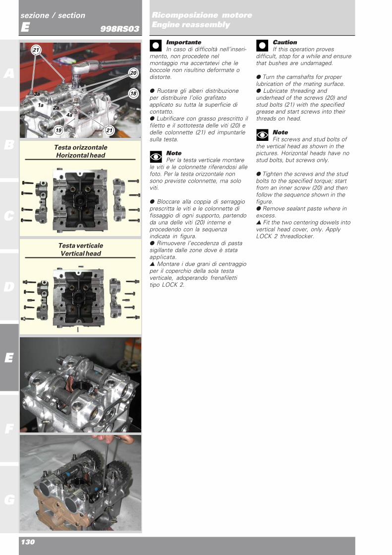
130
A
B
C
D
E
F
G
sezione / section
ERicomposizione motoreEngine reassembly998RS03
ImportanteIn caso di difficoltà nell’inseri-
mento, non procedete nelmontaggio ma accertatevi che leboccole non risultino deformate odistorte.
● Ruotare gli alberi distribuzioneper distribuire l’olio grafitatoapplicato su tutta la superficie dicontatto.● Lubrificare con grasso prescritto ilfiletto e il sottotesta delle viti (20) edelle colonnette (21) ed impuntarlesulla testa.
NotePer la testa verticale montare
le viti e le colonnette riferendosi allefoto. Per la testa orizzontale nonsono previste colonnette, ma soloviti.
● Bloccare alla coppia di serraggioprescritta le viti e le colonnette difissaggio di ogni supporto, partendoda una delle viti (20) interne eprocedendo con la sequenzaindicata in figura.● Rimuovere l’eccedenza di pastasigillante dalle zone dove è stataapplicata.▲ Montare i due grani di centraggioper il coperchio della sola testaverticale, adoperando frenafilettitipo LOCK 2.
CautionIf this operation proves
difficult, stop for a while and ensurethat bushes are undamaged.
● Turn the camshafts for properlubrication of the mating surface.● Lubricate threading andunderhead of the screws (20) andstud bolts (21) with the specifiedgrease and start screws into theirthreads on head.
NoteFit screws and stud bolts of
the vertical head as shown in thepictures. Horizontal heads have nostud bolts, but screws only.
● Tighten the screws and the studbolts to the specified torque; startfrom an inner screw (20) and thenfollow the sequence shown in thefigure.● Remove sealant paste where inexcess.▲ Fit the two centering dowels intovertical head cover, only. ApplyLOCK 2 threadlocker.
Testa orizzontale
Horizontal head
Testa verticale
Vertical head
21
20
2121
3a
1a2a
4a
18
19

Ricomposizione motoreEngine reassembly
131
sezione / section
E
A
B
C
D
E
F
G
Ricomposizione motoreEngine reassembly998RS03Verifica alzata valvole● A questo punto del montaggio èpossibile verificare se l’alzata dellevalvole corrisponde a quellaprescritta: per questa operazione ènecessario utilizzare gli appositicalibri dotati di comparatore etastatore a forcella:
- 88765.1283 per il cilindro verticale,- 041.1.053.1A per lo scarico del
cilindro orizzontale,- 041.1.054.1A per l’aspirazione del
cilindro orizzontale.
▲ Installare il supporto delcompara-tore sulle colonnette deisupporti alberi distribuzione, latoaspirazione e bloccarlo con delle vitiadatte.● Bloccare il comparatore nellasede del supporto con la segnatura“A” e posizionare il tastatore aforcella in appoggio sulla superficiedel registro di chiusura.● Azzerare il comparatore sullaposizione di valvola chiusa.▲ Inserire tra camma e pattinobilanciere apertura uno spessimetroper annullare il gioco.▲ Montare provvisoriamente lalinguetta e la puleggia sull’alberodistribuzione di aspirazione eruotarla facendole compiere unaalzata completa alle valvole diaspirazione.● Verificare sul comparatore delcalibro che il valore rilevatocorrisponda a quello prescritto.● Eseguire la stessa operazione perle valvole di scarico, spostando ilsupporto sulle colonnette opposte eposizionando il comparatore nellasede del supporto con la segnatura“S”.- Alzata valvole aspirazione: 14 mm.- Alzata valvole di scarico: 12 mm.
Tappi e anelli di tenuta alberidistribuzione▲ Dopo averli puliti, sgrassati einumiditi con alcool, procedere almontaggio dei tappi laterali (22) sullato opposto distribuzione conattrezzo 88713.2066. Installarli inpiano, con il lato cavo rivolto versol’estremità dell’albero distribuzione,verificando che la distanza dallasuperficie esterna della sede risultiuguale per tutta la circonferenza deltappo.
Checking valve lift● Now valve lift can be checked.Use gauges equipped with dialgauge and fork gauge stylus:
- 88765.1283 for vertical cylinder,- 041.1.053.1A for horizontalcylinder exhaust,- 041.1.054.1A for horizontalcylinder intake.
▲ Fit the dial gauge support ontothe stud bolts of camshaft supports,on intake side, and keep in positionwith proper screws.● Lock dial gauge in place intosupport where marked with “A” andthen fit the fork gauge stylus againstthe closing shim.● Set dial gauge to zero when thevalve is fully closed.▲ Fit a feeler gauge between camand opening arm shoe to take upany clearance.▲ Temporarily fit the key and thebelt roller on the camshaft and thenturn it to fully lift intake valves.● Ensure that the value taken by thedial gauge is as specified.● Repeat the same procedure forthe exhaust valves: the supportshould be on the other stud boltsand the dial gauge be positionedwhere marked with “S”.- Intake valve lift: 14 mm.- Exhaust valve lift: 12 mm.
Camshaft plugs and seals▲ Clean, degrease and wet withalcohol side plugs (22) on sideopposite to timing and then fit themusing tool part no. 88713.2066. Fitthem on a flat surface. Hollow sideshould face the camshaft end.Make sure that the distance of theseat from the other surface is thesame all around the plug.
22
88765.1283

132
A
B
C
D
E
F
G
sezione / section
ERicomposizione motoreEngine reassembly998RS03
● Inumidire con alcool la superficieesterna degli anelli di tenuta (23).▲ Inserire sull’estremità dell’alberodistribuzione la guida dell’attrezzo88713.1906 quindi montare l’anellodi tenuta.
ImportanteUtilizzare ad ogni rimontaggio
anelli di tenuta nuovi.
● Utilizzare il tampone dell’attrezzo88713.1906 e martello per l’inseri-mento in sede degli anelli di tenuta.
Cartelle laterali● Pulire le superfici di accoppiamen-to della testa e delle cartelle laterali.Verificare che queste ultime nonpresentino deformazioni o tracce dirottura quindi controllarne la plana-rità: in questo caso sostituire senzaindugio la cartella.● Controllare che sulla cartella (24),quella del lato opposto distribuzione,sia installato l’anello OR (25).● Per mantenere in posizione leguarnizioni OR sulla testa ed evitareche il loro spostamento, durante lafase di accoppiamento dellecartelle, possa pregiudicare latenuta, ingrassare leggermente lesedi su entrambi i lati della testa.● Disporre in corrispondenza deiperni bilancieri di chiusura laguarnizione OR (26, ellittica), incorrispondenza dei perni bilancieri diapertura le guarnizioni OR (27,ROSSE) e in corrispondenza deicondotti di passaggio acqua leguarnizioni OR (28, VERDI).
ImportanteUtilizzare ad ogni rimontaggio
guarnizioni OR nuove. Fare partico-lare attenzione a non scambiare leposizioni di montaggio delleguarnizioni (27) e (28) dimensional-mente simili.
▲ Procedere all’accoppiamentodella cartella (24) sul lato oppostodistribuzione della testa, utilizzandocome centraggio le estremità deiperni bilancieri di apertura.● Verificare, prima di impuntare leviti, che la luce tra testa e cartellarisulti uniforme su tutto il perimetro,indice di corretto posizionamentodelle guarnizioni OR.▲ Tenere premuta la cartella controla testa ed impuntare tutte le 9 viti difissaggio.▲ Bloccare tutte le viti alla coppia diserraggio prescritta, seguendo lasequenza numerica riportata infigura.
● Wet seals (23) with alcohol▲ Fit the guide of tool part no.88713.1906 onto the shaft end andthen fit the seal.
CautionAt reassembly, always fit new
seals.
● Tap on tool part no. 88713.1906with a hammer to seat the seals.
Side covers● Clean mating surfaces of headand side covers. Side covers shouldshow no signs of damages. Alsocheck they are flat. If not, replacethe cover.● Check that the OR seal (25) isfitted into the cover (24) on the sideopposite to timing.● Lightly grease OR seal seats oneither side of the heads to keepthem in position while matingcovers.● Fit the elliptic OR seal (26) atclosing rocker arm shafts, RED ORseals (27) at opening rocker armshafts and GREEN OR seals (28) atwater ducts.
CautionAt reassembly, always fit new
OR seals. Ensure to fit OR seals (27)and (28) in their correct positions,as they are very similar in size.
▲ Fit the cover (24) on the oppositeside to head timing; use openingrocker arm ends to center.● Ensure that the gap between headand cover is the same around thewhole perimeter before fitting thescrews. This means that OR sealsare correctly fitted.▲ Push the cover against the headand then start all 9 retaining screwsinto their threads.▲ Tighten all screws to the specifiedtorque, following the numbersequence shown in the figure.
23
24
2727 26
2727 26
25
28
28
24
18
94
5
3
62
7
88713.1906

Ricomposizione motoreEngine reassembly
133
sezione / section
E
A
B
C
D
E
F
G
Ricomposizione motoreEngine reassembly998RS03
▲ Eseguire le stesse operazioni peril montaggio delle guarnizioni OR edella cartella (29) sul latodistribuzione.▲ Bloccare le 11 viti di fissaggioalla coppia prescritta, seguendo lasequenza numerica riportata infigura.▲ Montare sulle cartelle latodistribuzione i perni per il fissaggiodei tenditori, adoperando frenafilettiprescritto. Per il serraggio dei pernitenditori adoperare l’attrez-zospeciale cod. 88713.1821 serran-dolo alla coppia prescritta.▲ Montare il tappo uscita olio (30)sul lato aspirazione.
Pulegge distribuzione● Verificare che la sede dellalinguetta sull’estremità degli alberidistribuzione risulti integra e senzabave.▲ Installare una linguetta (31) nellasede di ogni albero distribuzione.▲ Assemblare i componenti cheformano l’assieme puleggiainserendo la flangia (32) e lapuleggia (34) da fissare con le treviti (33) e la ghiera (35).
NoteDal momento che
successivamente si procederà allaregolazione della fase, utilizzare vitidi servizio (A) al posto delle tre viti(32) e una ghiera di servizio (34),ponendola nella posizione indicatacome “Soluzione di primo tentativoper fasatura motore” del capitolo“Fasatura distribuzione”.
● Inserire nelle pulegge l’attrezzo88713.1806 per bloccarne larotazione.
▲ Follow the same procedure forthe OR seals and the cover (29) ontiming side.▲ Tighten the 11 retaining screwsto the specified torque, following thenumber sequence shown in thefigure.▲ Fit the pins for tensioners into thecovers on timing side. Apply thespecified threadlocker. Tighten thetensioner pins to the specifiedtorque using tool part no.88713.1821.▲ Fit the oil plug (30) on intakeside.
Timing belt rollers● Ensure that the keyway oncamshaft ends is undamaged andwithout burrs.▲ Fit a key (31) into each camshaftseat.▲ Assembly the parts belonging tothe roller unit: fit the flange (32) andthe roller (34) to be fastened withthe three screws (33) and the ringnut (35).
NoteAs later timing needs
adjustment, use the screws (A)instead of the three screws (32) anda ring nut (34). Position the ring nutto “first engine timing” as specifiedunder “Timing”.
● Fit the tool part no. 88713.1806into the rollers so that they cannotturn.
A
29
106
8 3
4 5 11
1
2 7
9
B
31 32 33
34
30
35
88713.1806
88713.1821
2LOCK

134
A
B
C
D
E
F
G
sezione / section
ERicomposizione motoreEngine reassembly998RS03
ImportanteQuando si sostituiscono le viti
e le ghiere di servizio con quelledefinitive utilizzare sempre ad ognimontaggio ghiere nuove.
● Utilizzando la bussola in dotazioneall’attrezzo 88713.1806, abbinato aduna chiave dinamometrica, bloccarele ghiere (35) alla coppia di serraggioprescritta.
COMPONENTI SEMICARTER
I semicarter devono risultare integrie perfettamente puliti. Le superficidi accoppiamento devono risultareperfettamente piane ed esenti dabave.
NoteÈ estrememente importante
pulire molto accuratamente i carterponendo estrema attenzione anchea tutti i passaggi olio interni.
Semicarter lato frizioneSul lato interno del semicarter devo-no essere presenti:- il cuscinetto (1) di estremità
dell’albero secondario;- il cuscinetto (2) di supporto
dell’albero primario, fissato con vitie rosetta di ritegno;
- il cuscinetto di banco (3) conrelativa bussola;
- il cuscinetto a rulli (4) con seegerdi arresto (5) in corrispondenzadell’albero rinvio distribuzione.
Sul lato esterno del semicarter devo-no essere presenti:- i due nippli (6) per le tubazioni di
collegamento del radiatore olio conrelative rosette;
- il tappo (7) di chiusura delcondotto di lubrificazioneprincipale;
- serrare alla coppia prescritta;- il nipplo (8) per il filtro olio a
cartuc-cia, usando il frenafilettiprescritto;
- avvitare il tappo di chiusura by-pass radiatore e cianfrinare in 4punti a 90° (come rappresentatonell’illustrazione);
CautionWhen fitting final screws and
ring nuts, always use new ring nuts.
● Using the bush supplied with toolpart no. 88713.1806 together with atorque wrench, tighten the ring nuts(35) to the specified torque.
CASING PARTS
Casings should be undamaged andperfectly clean. Mating surfacesshould be perfeclty flat and withoutburrs.
NotePerfect cleaning of the
casings is of major importance,especially for inner oil through-holes.
Clutch-side casingThe following parts should be fittedinto the casing inner side:- bearing (1) for secondary shaft end
;- support bearing (2) for primary
shaft secured by means of screwsand check washer;
- main bearing (3) with bush;- roller bearing (4) with snap ring (5)
at timing lay shaft (5).
The following parts should be fittedinto the casing outer side:- two nipples (6) for oil cooler tubes
with wahsers;- plug (7) for main lubrication duct;- tighten the following to the
specified torque;- nipple (8) for oil cartridge filter.
Apply the required threadlocker ;- screw the cooler by-pass plug and
and caulk at 90° in 4 points (asshown in the figure);
4 3 2
1
4
7
5
6
8
88713.1806

Ricomposizione motoreEngine reassembly
135
sezione / section
E
A
B
C
D
E
F
G
Ricomposizione motoreEngine reassembly998RS03
▲ Montare il bocchettone (9) al disotto della flangia, insieme l’OR(10) interno alla flangia (11); infilareil tutto nella flangia filettata (12) ebloccare con l’anello elastico (13).▲ Avvitare l’insieme così ottenutosul semicarter interponendo larosetta (14) e, dopo aver orientatocorrettamente il bocchettone (15),sigillare il tutto con uno strato diTHREE BOND onde evitaretrasudamenti di olio.
Montaggio levetta fermomarcia▲ Inserire sulla vite di fissaggio (16)del dispositivo fissa marce, ilsaltarel-lo (17), la rosetta (18) e lamolla (19).▲ Applicare bloccante prescritto sulfiletto della vite (16).▲ Installare il dispositivo sulsemicarter lato frizione,posizionando l’estremità della molla(19) dietro l’apposita nervatura delcarter.● Bloccare la vite (16) alla coppiadi serraggio prescritta.
▲ Fit the filler (9) under the flangeand the OR seal (10) into the flange(11). Fit the whole assembly into thethreaded flange (12) and keep inposition with the snap ring (13).▲ Screw the unit onto the casinghalf. Put the washer (14) inbetweenand position the filler (15) properly,first. Apply THREE BOND so as toavoid oil dripping.
Assembling gear stoppinglever▲ Fit the ratchet (17), the washer(18) and the spring (19) onto theretaining screw (16) of the gearstopper.▲ Apply the specified threadlockerto the screw threading (16).▲ Fit the device onto the casing onclutch side; position the spring end(19) behind the case bead.● Tighten screw (16) to thespecified torque.
15
12 10 11
14 13 9
18 17
19 16
19 16

136
A
B
C
D
E
F
G
sezione / section
ERicomposizione motoreEngine reassembly998RS03Semicarter lato alternatoreSul lato interno del semicarterdevono essere presenti:- il cuscinetto (20) a doppia corona
di sfere di supporto dell’alberosecondario con relativa piastrina eviti di ritegno.
- il cuscinetto (21) di estremitàdell’albero primario cambio condistanziale interno;
- il cuscinetto di banco (22) conrelativa bussola;
- il cuscinetto sfere (23) con seegerdi arresto in corrispondenzadell’albero rinvio distribuzione.
NoteTutti i cuscinetti, esclusi quelli
di banco, non hanno un lato dimontaggio.
▲ Procedere al montaggio del filtroa rete (24) lubrificando leggermentecon olio motore le guarnizioni OR ditenuta. Spingerlo fino in battuta.
ImportantePer non danneggiare il filtro,
utilizzare solamente le mani perl’inserimento evitando l’impiego dimartello o altri attrezzi metallici,spingere il filtro olio facendopressione sul bordo più esterno.
● Sopra la sede del filtro a rete èmontato un tappo (25) di chiusuradel condotto di lubrificazione. Incaso di sostituzione, deve essererimontato applicando bloccanteprescritto sul filetto.
Alternator-side casingThe following parts should be fittedinto the casing inner side:- double ball crown bearing (20) for
secondary shaft, with plate andretaining screws.
- bearing (21) onto primary shaftend with inner spacer ;
- main bearing (22) with bush;- ball bearing (23) with snap ring at
timing lay shaft.
NoteAll bearings, but main
bearings, have no special assemblyside.
▲ Fit the mesh filter (24). Lightlylubricate the OR seals with engineoil. Drive fully home.
CautionFit the filter by hand so as not
to damage it. Do not use either ahammer or other metal tools. Pushthe oil filter from its outer edge.
● A plug (25) for the lubricationduct is above the mesh filter seat. Ifremoved, apply the specifiedthreadlocker before refitting.
24
23
20 21 22
23
24
25
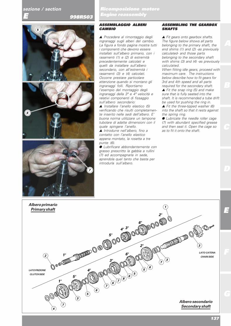
Ricomposizione motoreEngine reassembly
137
sezione / section
E
A
B
C
D
E
F
G
Ricomposizione motoreEngine reassembly998RS03ASSEMBLAGGIO ALBERICAMBIO
▲ Procedere al rimontaggio degliingranaggi sugli alberi del cambio.La figura a fondo pagina mostra tuttii componenti che devono essereinstallati sull’albero primario, con irasamenti (1) e (2) di estremitàprecedentemente calcolati equelli da installare sull’alberosecondario, con all’estremità irasamenti (3) e (4) calcolati.Occorre prestare particolareattenzione quando si montano gliingranaggi folli. Riportiamol’esempio del montaggio degliingranaggi della 3ª e 4ª velocità erelativi componenti di fissaggiosull’albero secondario:▲ Installare l’anello elastico (5)verificando che risulti completamen-te inserito nelle sedi dell’albero. E’buona norma utilizzare un tamponetubolare di adatte dimensioni con ilquale spingere l’anello.▲ Introdurre nell’albero, fino acontatto con l’anello elasticoappena montato, la rosetta a trepunte (6).● Lubrificare abbondantemente congrasso prescritto la gabbia a rullini(7) ed accompagnarla in sede,aprendola quel tanto che basta perintrodurla sull’albero.
ASSEMBLING THE GEARBOXSHAFTS
▲ Fit gears onto gearbox shafts.The figure below shows all partsbelonging to the primary shaft, theend shims (1) and (2) -as previouslycalculated- and those partsbelonging to the secondary shaftwith shims (3) and (4) -as previouslycalculated.When fitting idle gears, proceed withmaximum care. The instructionsbelow describe how to fit gears for3rd and 4th speed and all partsrequired for the secondary shaft.▲ Fit the snap ring (5) and makesure that is fully seated into theshaft. It is recommended a tube driftbe used for pushing the ring in.▲ Fit the three-tipped washer (6)into the shaft so that it rests againstthe spring ring.● Lubricate the needle roller cage(7) with abundant specified greaseand then seat it. Open the cage soas to fit it onto the shaft.
LATO FRIZIONE
CLUTCH SIDE
LATO CATENA
CHAIN SIDE
1
5
4
3
3
6
2
6
2
1
5
4
2
4
7
3
5
6
76
78
65
56
73
3
1Albero primario
Primary shaft
Albero secondario
Secondary shaft
5
6
7

138
A
B
C
D
E
F
G
sezione / section
ERicomposizione motoreEngine reassembly998RS03
▲ Montare l’ingranaggio della 3avelocità (8).▲ Installare sull’ingranaggio larosetta a tre punte (9), riconoscibilerispetto alle altre (6) dal maggiordiametro esterno.▲ Installare un’altra gabbia a rullini(7) nel modo già descritto.▲ Montare l’ingranaggio della 4avelocità (10).▲ Introdurre nell’albero un’altrarosetta a tre punte (6) e un altroanello elastico (5). Spingerlo in sedeutilizzando il tampone precedente-mente usato.
▲ Fit the 3rd speed gear (8).▲ Fit the three-tipped washer (9)onto the gear. This washer is largerthan the others (6).▲ Fit a needle roller cage (7) aspreviously described.▲ Fit the 4th speed gear (10).▲ Fit a three-tipped washer (6) anda snap ring (5) onto the shaft. Driveit fully home using the above drift.
8
9
10
7
5
6

Ricomposizione motoreEngine reassembly
139
sezione / section
E
A
B
C
D
E
F
G
Ricomposizione motoreEngine reassembly998RS03CHIUSURA SEMICARTER
▲ Installare sull’albero motore, suglialberi del cambio e sul tamburoselettore i rasamenti stabiliti con leprocedure di spessorazione descrittaal capitolo “Revisione motore”,quindi procedere al montaggio sulsemicarter lato frizione.● Verificare che siano installate ledue boccole di centraggio.● Dopo aver pulito e sgrassato lesuperfici di contatto, stendere unvelo di guarnizione liquida sulsemicarter, contornare tutti i foridelle viti e delle boccole senzalasciare tratti scoperti chepotrebbero provocare perdite di olio.▲ Dopo averlo opportunamenteingrassato per mantenerlo in sede,posizionare l’anello OR (11) incorrispondenza del canale dicomunicazione olio, tra i duesemicarter.
ImportanteAccertarsi che le bielle siano
correttamente posizionate nellerispettive sedi dei cilindri. Unposizionamento errato porterebbeinevitabilmente alla riapertura deisemicarter.
▲ Accoppiare i semicartereventualmente battendo conmartello in gomma in prossimitàdegli alberi.● Preparare le viti di fissaggiolubrificandole, con grasso prescritto,ed impuntarle sul semicarter latoalternatore, facendo attenzione alledifferenti lunghezze.
▲ Avvitare fino in battuta in modoprogressivo le viti di unione, partendoda quelle di diametro maggiore (M8).▲ Installare due viti M8 (A), sul latofrizione.▲ Serrare tutte le viti, partendo daquelle di diametro maggiore, allacoppia di serraggio prescritta.● Controllare che l’albero motoreruoti con una certa interferenza suicuscinetti di banco, ovvero controlla-re che il precarico sia sufficiente adimpedirne la rotazione in qualsiasiposizione esso venga abbandonato(in gergo l’albero non deve “cadere”).Ridurre o aumentare la spessorazio-ne dell’albero a seconda che esso siatroppo frenato o troppo libero.
rif./ref q.tà/q.ty descrizione/description
A 4 viti M8x90 mm/M8x90 mm screws
B 2 viti M8x75 mm/M8x75 mm screws
C 1 vite forata M8x75 mm/M8x75 mm
drilled screw
D 8 viti M6x35 mm/M6x35 mm screws
E 2 viti M6x75 mm/M6x75 mm screws
CLOSING THE CASINGS
▲ Fit the required shims -to beselected as specified under “Engineoverhaul”- into the crankshaft,gearbox shafts and selector drum.Then fit into the clutch-side casing.● Ensure that the two centeringbushes are properly fitted.● Clean and degrease all matingsurfaces, then apply a thin layer ofliquid gasket onto the casing,following the profile of all screw andbush holes. Ensure that liquid gasketis where required, as oil might leakfrom the casing.▲ Grease and fit the OR seal (11)into the oil groove between the twocasings.
CautionEnsure that the con-rods are
properly seated into the cylinders. Ifnot, the casings should be laterreopened.
▲ Tap the casings close to theshafts for proper mating.● Lubricate the retaining screwswith the specified grease and fitthem in the LH-side casing. Payattention as screws have differentlenghts.
▲ Drive the jointing screws fullyhome starting from the larger ones(M8).▲ Fit the two M8 screws (A) onclutch side.▲ Tighten all screws to the specifiedtorque starting from the largest one.● Ensure that the crankshaft issubject to a certain friction onto themain bearings while turning. Thismeans that the preload should beenough so to avoid shaft rotation if itstops in any position (it should not“fall down”). Add or remove shimsso to have a properly braked shaft.
A
B
C
11
E
D
A
D
D

140
A
B
C
D
E
F
G
sezione / section
ERicomposizione motoreEngine reassembly998RS03
● Controllare che tutti gli organimontati ruotino o si spostinocorrettamente.▲ Installare il coperchio (12) di ac-cesso al filtro a rete con guarnizione.▲ Bloccare le viti di fissaggio allacoppia prescritta.▲ Installare il tappo di scarico (13)con guarnizione e bloccarlo allacoppia prescritta.▲ Lubrificare con olio motore laguarnizione OR di tenuta edinstallare il filtro a cartuccia,preventivamente riempito d’oliomotore.▲ Bloccarlo alla coppia prescrittautilizzando l’attrezzo 06750.3210abbinato ad una chiavedinamometrica.▲ Ingrassare la guarnizione OR ditenuta (14).▲ Inserirla sull’albero secondariodel cambio facendole oltrepassarela parte zigrinata del cambio stessosenza danneggiarla.▲ Inserire il distanziale pignonecatena (15).
● Make sure that all parts can turnor move freely.▲ Fit the cover (12) protecting themesh filter with seal.▲ Tighten the retaining screws tothe specified torque.▲ Fit the drain plug (13) with sealand tighten to the specified torque.▲ Lubricate the OR seal with engineoil and fit the cartridge filter -previously filled with engine oil.▲ Tighten it to the specified torqueusing the tool part no. 06750.3210and a torque wrench.▲ Grease the OR seal (14).▲ Fit the OR seal into the gearboxsecondary shaft. Do not damage theOR seal while moving over the shaftknurled section.▲ Fit the chain sproket spacer (15).
1514
06750.3210
12
13

Ricomposizione motoreEngine reassembly
141
sezione / section
E
A
B
C
D
E
F
G
Ricomposizione motoreEngine reassembly998RS03MONTAGGIO LEVERAGGIOSELEZIONE MARCE
● Posizionare il leveraggio diselezione marce completo dialberino di comando, molla epiastrina.● Posizionare la forcella comandotamburo del cambio centratorispetto ai rullini del tamburo.▲ Montare provvisoriamente la levadel cambio (o una leva di servizio) eil pignone motore e mettere ilcambio in terza marcia.▲ Installare il piastrino 88713.1091nei perni dell’albero comandoforcelle (vedi figura a fianco).● Allineare la tacca, corrispondentealla mezzeria dell’arpione dispostamento albero comandoforcelle, con l’estremità delpiastrino.▲ Su questa posizione serrare le viti(1) e (2), con rosetta zigrinata difissaggio del leveraggio di selezionemarce.● Con cambio in posizione di riposoverificare che la corsa della leva infase di innesto e in scalata risultiuguale. Analoga situazione deveverificarsi anche con marcia inserita.● Agendo sulla leva comandocambio e contemporaneamenteruotando il pignone provarel’inserimento di tutte le marce infase di innesto e in scalata.❍ Rimuovere leva e pignone.
ASSEMBLING THE GEARSELECTOR LEVER
● Position the gear selector levercomplete with control shaft, springand plate.● Center the drum control fork todrum rollers.▲ Temporarily fit the gear lever (or aservice lever) and the front sprocket.Then engage the third speed.▲ Fit the plate 88713.1091 into thefork control shaft pins (see figure).● Align the notch for center line ofthe fork shaft latch with the plateend.▲ When in this position, tighten thescrews (1) and (2), with the knurledwasher of gear selection lever.● Then set the gearbox to restposition and ensure that the levertravel is the same while shifting upand down. The same should appy ifa gear is engaged.● Pull/push the gearbox controllever and turn the sprocket at thesame time to shift up and down.❍ Remove lever and sprocket.
1
2
88713.1091
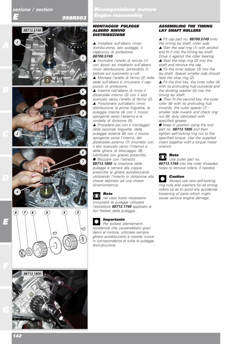
142
A
B
C
D
E
F
G
sezione / section
ERicomposizione motoreEngine reassembly998RS03MONTAGGIO PULEGGEALBERO RINVIODISTRIBUZIONE
▲ Installare sull’albero rinviodistribu-zione, lato pulegge, ilcappuccio di protezione88700.5749.▲ Inumidire l’anello di tenuta (1)con alcool ed installarlo sull’alberorinvio distribuzione, portandolo inbattuta sul cuscinetto a rulli.▲ Montare l’anello di fermo (2) nellasede sull’albero e rimuovere il cap-puccio di protezione.▲ Inserire nell’albero di rinvio ildistanziale interno (3) con il latoscaricato verso l’anello di fermo (2).▲ Posizionare sull’albero rinviodistribuzione la prima linguetta, lapuleggia interna (4) con il mozzosporgente verso l’esterno e larondella di divisione (5).▲ Procedere poi con il montaggiodella seconda linguetta, dellapuleggia esterna (6) con il mozzosporgente verso l’interno, deldistanziale esterno (7) (montato conil lato scaricato verso l’interno) edella ghiera di bloccaggio (8),lubrificata con grasso prescritto.● Bloccare con l’attrezzo88713.1805 la rotazione dellepulegge e serrare alla coppiaprescritta la ghiera autobloccanteutilizzando l’inserto in dotazione allachiave abbinato ad una chiavedinamometrica.
Notenel caso fosse necessario
rimuovere le pulegge utilizzarel’estrattore 88713.1749 applicato aifori filettati della puleggia.
ImportantePer evitare allentamenti
accidentali che causerebbero gravidanni al motore, utilizzare sempreghiere autobloccanti e rosette nuovein corrispondenza di tutte le puleggedistrubuzione.
ASSEMBLING THE TIMINGLAY SHAFT ROLLERS
▲ Fit cap part no. 88700.5749 ontothe timing lay shaft -roller side.▲ Wet the seal ring (1) with alcoholand fit it into the timing lay shaft.Drive it against the roller bearing.▲ Seat the stop ring (2) into theshaft and remove the cap.▲ Fit the inner spacer (3) into thelay shaft. Spacer smaller side shouldface the stop ring (2).▲ Fit the first key, the inner roller (4)with its protruding hub outwards andthe dividing washer (5) into thetiming lay shaft.▲ Then fit the second key, the outerroller (6) with its protruding hubinwards, the outer spacer (7) -smaller side inward- and check ringnut (8) -duly lubricated withspecified grease.● Keep in position using the toolpart no. 88713.1805 and thentighten self-locking ring nut to thespecified torque. Use the suppliedinsert together with a torque meterwrench.
NoteUse puller part no.
88713.1749 into the roller threadedholes to remove rollers, if needed.
CautionAlways use new self-locking
ring nuts and washers for all timingrollers so as to avoid any accidentalloosening of parts which mightcause serious engine damage.
8 7 6 5 4 3
1
5
4
3
8
7
2
2
6
88713.5749
88713.1805

Ricomposizione motoreEngine reassembly
143
sezione / section
E
A
B
C
D
E
F
G
Ricomposizione motoreEngine reassembly998RS03MONTAGGIO INGRANAGGICOMANDO DISTRIBUZIONE
▲ Posizionare le linguette (1) e (2)nelle rispettive cave dell’alberocomando distribuzione e dell’alberomotore.▲ Inserire gli ingranaggi suirispettivi alberi allineando iriferimenti presenti sulla coronadentata (vedi illustrazio-ne a fianco).● Verificare che non ci siainterferenza tra gli ingranaggi.▲ Posizionare sull’albero comandodistribuzione la rondella disicurezza (3) e il dado (4),lubrificato con grasso prescritto.▲ Bloccare il dado (4) alla coppiaprescritta, facendo reazione sullapuleggia con l’attrezzo 88713.1932,sul lato opposto dell’albero.● Ripiegare la rondella (3) sul dado(4).
ASSEMBLING THE TIMINGCONTROL GEARS
▲ Position the keys (1) and (2) intotheir seats on camshaft andcrankshaft.▲ Fit the gears into the shafts andalign them with the marks on thesprocket (see figure)● Ensure that gears can movefreely.▲ Lubricate the nut (4) withspecified grease and then fit the nutand the safety washer (3) into thecamshaft.▲ Tighten nut (4) to the specifiedtorque while keeping the roller withtool part no. 88713.1932, on the sideopposite to the shaft.● Bend washer (3) onto nut (4).
1
2
43
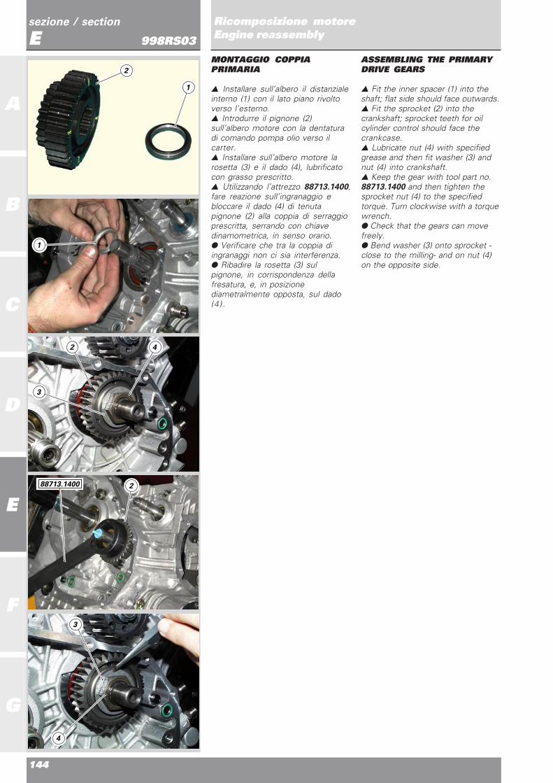
144
A
B
C
D
E
F
G
sezione / section
ERicomposizione motoreEngine reassembly998RS03MONTAGGIO COPPIAPRIMARIA
▲ Installare sull’albero il distanzialeinterno (1) con il lato piano rivoltoverso l’esterno.▲ Introdurre il pignone (2)sull’albero motore con la dentaturadi comando pompa olio verso ilcarter.▲ Installare sull’albero motore larosetta (3) e il dado (4), lubrificatocon grasso prescritto.▲ Utilizzando l’attrezzo 88713.1400,fare reazione sull’ingranaggio ebloccare il dado (4) di tenutapignone (2) alla coppia di serraggioprescritta, serrando con chiavedinamometrica, in senso orario.● Verificare che tra la coppia diingranaggi non ci sia interferenza.● Ribadire la rosetta (3) sulpignone, in corrispondenza dellafresatura, e, in posizionediametralmente opposta, sul dado(4).
ASSEMBLING THE PRIMARYDRIVE GEARS
▲ Fit the inner spacer (1) into theshaft; flat side should face outwards.▲ Fit the sprocket (2) into thecrankshaft; sprocket teeth for oilcylinder control should face thecrankcase.▲ Lubricate nut (4) with specifiedgrease and then fit washer (3) andnut (4) into crankshaft.▲ Keep the gear with tool part no.88713.1400 and then tighten thesprocket nut (4) to the specifiedtorque. Turn clockwise with a torquewrench.● Check that the gears can movefreely.● Bend washer (3) onto sprocket -close to the milling- and on nut (4)on the opposite side.
1
2
1
2
2
3
4
4
3
88713.1400

Ricomposizione motoreEngine reassembly
145
sezione / section
E
A
B
C
D
E
F
G
Ricomposizione motoreEngine reassembly998RS03RIMONTAGGIO VOLANO EROTORE ALTERNATORE
▲ Inserire sull’albero motore ildistanziale interno (1).▲ Qunidi il gruppo volano motore(2) con il riferimento allineato con lascalanatura sull’albero motore.▲ Inserire la molla a tazza (3) con laparte più larga rivolta verso ilvolano.▲ Inserire il dado (4) ed impuntare amano.● Bloccare la rotazione del volanocon l’attrezzo cod. 88713.1419 eserrare il dado alla coppia prescritta.
ASSEMBLING THE FLYWHEELAND ROTOR
▲ Fit the inner spacer (1) into thecrankshaft.▲ Then fit the flywheel assembly(2). The mark should be aligned withthe crankshaft groove.▲ Fit the Belleville washer (3); itslarger side should be facing theflywheel.▲ Install the nut (4) and snug it byhand.● Keep the flywheel in position withthe tool part no. 88713.1419 andtighten nut to the specified torque.
2
1
2
4
3
3
4 1
88713.1419

146
A
B
C
D
E
F
G
sezione / section
ERicomposizione motoreEngine reassembly998RS03MONTAGGIO POMPA ACQUAE COPERCHIO ALTERNATORE
▲ Infilare la rosetta (1), il cuscinettoschermato (2) ed infine il cuscinetto(3).▲ Inserire la rosetta (1) con lospigolo vivo rivolto verso ilcuscinetto come illustra il disegno insezione riportato a lato.▲ Piantare i due cuscinetti nelcarter, riscaldando preventivamentela zona di inserimento con un phon espingendo i cuscinetti con unapposi-to tampone, in modo daspingere sull’anello esterno deicuscinetti.▲ Montare le due viti con relativarosetta (il lato zigrinato deve essererivolto verso la testa della vite) eserrale alle coppie prescritte.▲ Montare sul coperchio alternatoreil cuscinetto (4) di estremitàdell’albero motore con relativoanello di ritegno (5).▲ Montare il distanziale statore (10)alternatore con l’alternatore (6)bloccandoli con le 3 viti (7).▲ Montare la piastrina bloccaggiocavo uscita con le due viti relative(8).▲ Montare i due bocchettoni uscitaacqua (9).● Capovolgere il coperchio.● Passare uno strato di grasso sullasede controfaccia.
ASSEMBLING THE WATERPUMP AND THE ALTERNATORCOVER
▲ Fit washer (1), shielded bearing(2) and bearing (3).▲ Fit washer (1). Its sharp edgeshould face the bearing, as shown inthe cross section drawing.▲ Heat up the bearing seat with ahairdryer and then drive the twobearings into the casing using a driftpositioned onto the bearing outerring.▲ Fit the two screws and theirwashers. The knurled side of thewasher should face the screw head.Tighten to the specified torque.▲ Fit the bearing (4) and its stopring (5) into the alternator cover.▲ Fit the stator spacer (10) andalternator (6). Secure by means ofthe three screws (7).▲ Fit the cable plate by means ofthe two screws (8).▲ Fit the two water fillers (9).● Turn the cover upsidedown.● Apply a layer of grease into thecounterface seat.
Schermatura
Shield
Spigolo vivo
Sharp edge
Spigolo smussato
Beveled edge
5 10
4
9
1
2
1
29
3
7
8
6
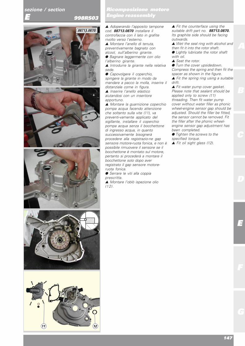
Ricomposizione motoreEngine reassembly
147
sezione / section
E
A
B
C
D
E
F
G
Ricomposizione motoreEngine reassembly998RS03
▲ Adoperando l’apposito tamponecod. 88713.0870 installare ilcontrofaccia con il lato in grafiterivolto verso l’esterno.▲ Montare l’anello di tenuta,preventivamente bagnato conalcool, sull’alberino girante.● Bagnare leggermente con oliol’alberino girante.▲ Introdurre la girante nella relativasede.● Capovolgere il coperchio,spingere la girante in modo damandare a pacco la molla, inserire ildistanziale come in figura.▲ Inserire l’anello elasticoaiutandosi con un inseritoreapportuno.▲ Montare la guarnizione coperchiopompa acqua facendo attenzioneche soltanto sulla vite (11), vapreventi-vamente applicato delsigillante, installare il coperchiopompa acqua senza il bocchettonedi ingresso acqua, in quantosuccessivamente bisogneràprocedere alla registrazio-ne gapsensore motore-ruota fonica, e non èpossibile rimuovere il sensore se ilbocchettone è montato sul motore,pertanto si procederà a montare ilbocchettone solo dopo averregistrato il gap sensore motore-ruota fonica.● Serrare le viti alla coppiaprescritta.▲ Montare l’oblò ispezione olio(12).
▲ Fit the counterface using thesuitable drift part no. 88713.0870.Its graphite side should be facingoutwards.▲ Wet the seal ring with alcohol andthen fit it into the rotor shaft.● Lightly lubricate the rotor shaftwith oil.▲ Seat the rotor.● Turn the cover upsidedown.Compress the spring and then fit thespacer as shown in the figure.▲ Fit the spring ring using a suitabledrift.▲ Fit water pump cover gasket.Please note that sealant should beapplied only to screw (11)threading. Then fit water pumpcover without water filler as phonicwheel-engine sensor gap should beadjusted. Should the filler be fitted,the sensor cannot be removed. Fitthe filler after the phonic wheel-engine sensor gap adjustment hasbeen completed.● Tighten the screws to thespecified torque.▲ Fit oil sight glass (12).
11 12
88713.0870

148
A
B
C
D
E
F
G
sezione / section
ERicomposizione motoreEngine reassembly998RS03
● Pulire da eventuali incrostazioni esgrassare le superfici di accoppia-mento del semicarter sinistro e delcoperchio alternatore.▲ Montare le due boccole diriferimento.● Applicare un cordone continuo euniforme di guarnizione liquidaTHREE BOND sulla superfice delcoperchio, contornando i fori delleviti e delle boccole di fissaggio.● Lubrificare con grasso l’estremitàdell’albero motore e dell’alberinoinserimento marce per facilitarel’inserimento del coperchio edevitare di danneggiare l’anello ditenuta, se rimane montato nelcoperchio.● Mentre si posiziona il coperchiosul semicarter, muovereleggermente le puleggedistribuzione sull’albero di rinvio peragevolare l’inserimento dell’alberinodi comando pompa.● Battere in più punti con martelloin gomma per aiutare l’inserimentodel coperchio negli alberi e nelleboccole di centraggio.
NoteNel caso fosse necessario
rimuovere il coperchio, utilizzarel’estrattore 88713.1435 applicato neifori filettati in corrispondenzadell’albero motore.
▲ Impuntare le viti di fissaggioseguendo le indicazioni dellatabella.
● Serrare alla coppia prescritta leviti di fissaggio.● Inumidire con alcool l’anello ditenuta (12) e montarlo sul coperchioalternatore, in corrispondenzadell’alberino leva cambio,utilizzando l’attrezzo cod.88713.2163.● Inumidire con alcool il paraolio edinstallarlo nel semicarter lato catenasull’albero secondario del cambioutilizzando l’attrezzo cod.88713.2163.
rif./ref q.tà/q.ty descrizione/description
A 9 viti M6x20 mm/M6x20 mm screws
B 2 viti M6x25 mm/M6x25 mm screws
C 2 viti M6x30 mm/M6x30 mm screws
● Remove any deposits from themating surfaces of LH-side casingand alternator cover and thendegrease.▲ Fit the two locating bushes.● Apply a thick layer of THREEBOND liquid gasket onto the cover.Avoid screw and bush holes.● Lubricate the crankshaft end andthe gear engagement shaft withgrease. If is still in the cover, makesure that the seal ring is notdamaged.● Lightly turn the timing rollers inthe lay shaft while fitting the coveronto the casing to make pumpcontrol shaft fitting easier.● Gently tap with a rubber mallet atdifferent points of the surface to helpthe cover fitting onto shaftsand centering bushes.
NoteIf the cover needs to be
removed, use puller 88713.1435,which should be fitted into thecrankshaft threaded holes.
▲ Fit the retaining screws incompliance with the indicationsgiven in the table below.
● Tighten the retaining screws tothe specified torque.● Wet the seal ring (12) with alcoholand fit it into the alterntor coverclose to the gear lever shaft. Usetool part no. 88713.2163.● Wet the oil seal with alcohol andthen fit it into the chain side casing-onto the gearbox secondary shaft.Use the tool part no. 88713.2163.
A
A
C
12
C A
B
A

Ricomposizione motoreEngine reassembly
149
sezione / section
E
A
B
C
D
E
F
G
Ricomposizione motoreEngine reassembly998RS03CONTROLLO TRAFERROSENSORE MOTORE
▲ Montare il sensore Pick-up (1).❍ Rimuovere il tappo a vite chechiude il foro di ispezione sulsemicarter sinistro (2).▲ Introdurre dal foro la lama di unospessimetro, posizionandola tral’estremità del sensore e il dentedella corona rinvio distribuzione.● Verificare che il gioco presenterisulti 0,70÷0,80 mm. In casocontrario rimuovere il sensore emodificare lo spessore dellaguarnizione.▲ Rimontare il tappo conguarnizione e bloccarlo alla coppiaprescritta.▲ Montare il bocchettone diaspirazione acqua orizzontale (3)sul coperchio alternatore,applicando bloccante prescritto, ebloccandolo alla coppia di serraggioprescritta.
NoteIn caso di rimontaggio di un
coperchio alternatore completo, ilbocchettone di aspirazione puòimpedire lo smontaggio del sensoremotore.
● Effettuare la stessa verifica per ilsensore numero di giri.
MONTAGGIO POMPA OLIO
● La pompa olio prima delmontaggio sul carter deve risultarecompletamente piena di olio motoree completa di valvola by-pass (3).▲ Posizionare le boccole diriferimento (4) e gli anelli OR (5) e(6) di tenuta olio in corrispondenzadei canali di lubrificazione delcarter.
NoteGli anelli OR (5) e (6) sono
differenti. Quello di diametromaggiore (6), va posizionato afianco della boccola di riferimentoinferiore.
▲ Posizionare la pompa olio sulcarter e bloccare le viti alla coppiaprescritta, lubrificando filetto esottotesta con grasso prescritto.● Controllare che non vi siainterferenza tra pignone motore edingranaggio comando pompa olio.
CHECKING THE AIR GAP OFSENSORS
▲ Fit Pick-up sensor (1).❍ Remove the screw plug for theinspection hole into the LH-sidecasing (2).▲ Fit a feeler gauge from the hole.Position the gauge between thesensor end and the timing lay gear● Ensure that the gap is 0.70÷0.80mm. If not, remove the sensor anduse a seal with a different thickness.▲ Refit the plug and its seal andtighten to the specified torque.▲ Fit the horizontal intake waterfiller (3) onto the alternator cover.Apply the specified sealant and thentighten to the specified torque.
NoteIf a complete alternator cover
is fitted, the intake filler might be inthe way when removing the enginesensor.
● Also check the rpm sensor.
ASSEMBLING THE OIL PUMP
● When fitting the oil pump, ensurethat it is full with engine oil and hasthe by-pass valve (3).▲ Fit the locating bushes (4) andthe OR seals (5) and (6) into thecasing lubrication ducts.
NoteThe OR seals (5) and (6) are
not interchangeable. The larger one(6) should be fitted close to thelower locating bush.
▲ Fit the oil pump onto the casing.Lubricate the screw threading andunderhead with the specified greaseand then tighten to the specifiedtorque.● Ensure that both sprocket and oilpump drive gear can move freely.
2 1 3
4
3
6
5

150
A
B
C
D
E
F
G
sezione / section
ERicomposizione motoreEngine reassembly998RS03RICOMPOSIZIONECOPERCHIO FRIZIONE EFRIZIONE
▲ Montare all’internodell’ingranaggio condotto dellatrasmissione primaria (1) i duecuscinetti (2), (3), riscaldando lasede e spingendo con un appositotampone che prema sull’anelloesterno dei cuscinetti, interponendotra loro il seeger (4) e la rosetta (5).▲ Installare l’anello di tenuta,preventivamente bagnato con alcoolcon il labro di tenuta rivolto verso idue cuscinetti.● Prima di montare il coperchiofrizione è necessario verificare cheal suo interno, in corrispondenzadell’alloggiamento dell’alberomotore, risulti installata la boccolaforata e l’anello di tenuta (6) conrosetta e anello seeger di ritegno.● In caso di sostituzione dell’anellodi tenuta (6) rimontare il particolarenuovo posizionandolo con il latoprovvisto di molla rivolto verso ilcoperchio (lato da cui arriva il flussodell’olio).
ImportanteVerificare che la rosetta non
entri nella sede del seeger diritegno.
▲ In corrispondenza dell’alberoprimario deve essere montatol’anello di tenuta (7) che lavora sulmozzo dll’ingranaggio dellatrasmissione primaria.● Stendere un leggero strato digrasso sul labbro di tenuta delparaolio della primaria (7).▲ Infilare l’ingranaggio condottodella coppia primaria all’interno delparaolio installato nel coperchiofrizione, operando con moltaattenzione ed evitando didanneggiare il labbro del paraolio.
ASSEMBLING THE CLUTCHAND THE CLUTCH COVER
▲ Heat up the seat of the twobearings (2) and (3) and then fitthem into the driven gear of theprimary drive gears (1) using asuitable drift positioned onto thebearing outer ring. Put the snap ring(4) and the washer (5) inbetween.▲ Wet the seal ring with aclohol andthen fit it. Its seal lip should face thetwo bearings.● Ensure that the drilled bush, theseal ring (6), the washer and thecheck snap ring are fitted into thecrankshaft seat before fitting theclutch cover.● If the seal ring (6) needsreplacing, fit the new part with itsspring side facing the cover (oil flowside)
CautionEnsure that the washer cannot
enter the check snap ring seat.
▲ The seal ring (7) should be fittedinto the drive shaft. This ring acts onthe primary drive gear hub.● Apply a thin layer of grease ontothe seal lip of the primary drive gearoil seal (7).▲ Fit the driven gear of the primarydrive gears into the oil seal fittedinto the clutch cover. Proceed withmaximum care, not to damage theoil seal lip.
2 1 4 5 3
6 7

Ricomposizione motoreEngine reassembly
151
sezione / section
E
A
B
C
D
E
F
G
Ricomposizione motoreEngine reassembly998RS03
▲ Appoggiare la campana frizione incorrispondenza dell’anello internodell’ingranaggio coppia primaria edimpuntare le viti a mano.▲ Serrare le viti alla coppiaprescritta, procedendo a croce.● Pulire e sgrassare le superfici dicontatto sul coperchio e sulsemicarter e verificare che suquest’ultimo siano installati laboccola di centraggio e laguarnizione OR in corrispondenzadel condotto di passaggio olio.● Applicare un cordone uniforme econtinuo di guarnizione liquidaTHREE BOND sulla superficie diaccoppiamento del semicarter,contornando tutti i fori.▲ Appoggiare il coperchio sul cartered impuntare le viti a mano, serrarlepoi alla coppia prescrittaprocedendo a croce.
▲ Position the clutch housing ontothe ring into the primary gear. Thensnug screws by hand.▲ Tighten the screws to thespecified torque, working crossways.● Clean and degrease matingsurfaces of casings and cover.Ensure that the centering bush andthe OR seal in the oil duct are fittedinto the cover.● Appy a thick layer of THREEBOND liquid gasket onto the casingmating surface. Avoid holes.▲ Position the cover onto the casingand then snug screws by hand.Tighten to the specified torque,working crossways.

152
A
B
C
D
E
F
G
sezione / section
ERicomposizione motoreEngine reassembly998RS03
▲ Montare sull’albero primario laguarnizione OR (9), facendolesuperare manualmente la partefilettata dell’albero stesso.▲ Inserire poi la boccola (8) quindiinstallare la molla a tazza (10), conil lato concavo rivolto verso laflangia.● Ingrassare le rampe di salita deldispositivo antisaltellamento sullaflangia (11) e sul tamburo (12)quindi posizionare nelle rispettivesedi le sei sfere (13).▲ Montare flangia (11) e tamburo(12) sull’albero primario.● Ingrassare le sedi di lavoro delleestremità della molla antislittamento(14) sul tamburo, quindi installare lamolla con distanziale centratore(15), posizionati come in figura.
▲ Fit the OR seal (9) on the primaryshaft. Move it over the shaftthreading .▲ Fit the bush (8) and then theBelleville washer (10); convex sideshould face the flange.● Grease the rise ramps of the anti-slip device on the flange (11) anddrum (12). Then the fit the six balls(13) into their seats.▲ Fit the flange (11) and the drum(12) into the primary shaft.● Grease the working seats of theanti-slip spring (14) on the drum.Then fit the spring with centeringspacer (15), as shown in the figure .
111312
10 8 9
14 15
10
8
9