Embed Size (px)
Citation preview

VALVE & PRIMER CORPORATION1420 WRIGHT BLVD. • SCHAUMBURG, IL 60193-4599847.524.9000 • FAX:847.524.9007 • 800.323.6969website: www.apcovalves.com • e-mail: [email protected]
2 0 0 8E d i t i o n
103
40
0S
EW
AG
E A
IR V
ALV
ES
Gen
erat
ion
IIA
IRV
ALV
ES
®
Sewage Air Vacuum ValveSERIES 401 SAVVCONCAVE FLOAT* (Patented)
Sewage Air Release ValveSERIES 400 SARV
Sewage Combination Air ValveSERIES 440 SCAV
BU
LL
ET
IN
1

104
GENERATION IIAPCO AIR VALVES FOR
SEWAGE PIPELINE SYSTEMSEFFECTS OF AIR in a pressurized closed-pipeline system must be recognized. An air pocket will decrease thecross sectional area and increase frictional pressure loss. The combined loss for two-phase flow (air & water)is always greater than the pressure loss for each phase flowing alone. Thus, air in a pipeline increases systemflow resistance and increases system head against which pumps must operate.
AIR MAY ENTER A PIPING SYSTEM IN MANY WAYS:(1) Air in the pipeline when initially filled may not be completely purged.(2) Air may be drawn in at a pump inlet by entrainment if the liquid level falls below the inlet elevation.(3) Air in solution (about 2% by volume) will be released at points in the pipeline where the pressure
is reduced, especially where the line elevation is close to the hydraulic gradient.(4) Gas created from digested sewage.(5) Air may be drawn in through packings, seals and flanged joints.(6) Air may enter by vortexing at the pump.
AIR IN PIPING tends to collect at high points in the line when flow velocities are low. If the air pocketformed is large, part of it will be removed when the velocity increases. This partitioned air may or may not gothrough the system. It all depends on velocity, pipe size, and pipe down-slope. It may only move into the sloping straight section and then return to the summit when the velocity decreases.
While it is impossible to totally prevent accumulation of air (or gases) within the piping system, the volumecan be greatly minimized by installing APCO Sewage Air Release Valves.
When air is present in a hydraulic pipeline, flows are erratic, unpredictable and have high head losses.Sewage works require Air Release Valves on pipeline high points.
All APCO Sewage Valves are furnished for 150 psi. Higher pressures available. Specify if operatingpressure is below 20 psi for a lower durometer seat.
BACKFLUSHING ATTACHMENTSOPTIONAL FOR ALL SEWAGE VALVESEXCEPT CUSTOM COMBINATIONS
While sewage media is standing in the valve body, sediment will attempt settling out at the bottom. This sediment maybe flushed out periodically.After installation, Sewage Valves should be inspected to determine need to backflush approximately once a year.Inspection takes only a few minutes and is simple:
1. Shut off the inlet valve.2. Open the blow off valve and observe…if fluid drains out the valve body rapidly, flushing is not required.
Should heavy suspended solids and grease be anticipated, attachments shown are recommended for ease of flushing.
2

105
40
0S
EW
AG
E A
IR V
ALV
ES
Gen
erat
ion
IIA
IRV
ALV
ES
BU
LL
ET
IN
SEWAGE COMBINATION AIR VALVESeries 440 SCAV
Series 440 SCAV
• First in a Single Body• No Spills• No Spurts• Shorter
MODEL SIZE INLET OUTLET DIA.VALVE PLAIN
HEIGHT WEIGHTWITH
ATTACHMENTSWITH
ATTACHMENTS
443 1” 2”NPT 1”NPT 191⁄2 241⁄2 91⁄2 87 95
445 2” 2”NPT 2”NPT 201⁄2 27 91⁄2 93 100
447 3” 3”NPT 3”NPT 231⁄2 291⁄2 11 147 157
449 4” 4”NPT 4”NPT 231⁄2 30 11 150 175
456 6” 6” 35 39 133⁄4 242 2976”125LB.FLANGE
CONCAVE FLOAT*PATENTED
Now, APCO brings you THE LATEST STATE OF THE ART SewageAir Valve design: a Single Body, Double Orifice “Sewage CombinationAir Valve”.GENERATION II…a new generation of Air Valve Design.Field tested under actual operating conditions. Incorporating all features that have made the 400 Sewage Air Release Valves and 401Sewage Air/Vacuum Valves the world’s finest…Now in a SingleBody-plus a New Concave Float* - to give even greater performanceand reliability.You no longer need to DIG DEEPER TRENCHES OR BUILDDEEPER VAULTS BECAUSE THE 440 SERIES IS AT LEAST 30%SHORTER THAN OTHER MODELS!Valves that won’t spill or spurt before shutting off. No more messywaste flooded valve vaults to pump out…or Pump Station floors tomop up…it shuts off drop tight.Take a serious look at GENERATION II - APCO Sewage Valves.Manufactured to our industry’s highest standards providing thehighest efficiency and reliability of any sewage air valve availablein the market today.
3

106
SPECIFY APCO WITH CONFIDENCE - SEWAGE COMBINATION AIR VALVE SERIES 440 SAVVSewage Combination Air Valve (SINGLE BODY, DOUBLE ORIFICE) to allow large volumes of air to escape or enter through the larger diameterorifice when filling or draining a pipeline.When the pipeline is filled and pressurized the large air/vacuum orifice shall stay closed, but the smaller diameter air release orifice shall remainoperative and open to allow small pockets of air accumulation to escape automatically and independently of the large orifice. The large air/vacuum orifice shall shut off when the free floating-center guided plug is raised into the orifice by the lifting force of the CONCAVE -bottom FLOAT*. The large orifice shut-off shall be “WITHOUT SPILLING”.The Buna-N seat must be fastened to the valve cover, without distortion, for drop-tight shut-off.The overall height & width shall not exceed the dimensions shown on this table.Optional - Inlet and blow off valves, quick disconnect couplings and minimum 5’ hose for flushing. (Engineer to specify).Materials of construction shall be certified the following A.S.T.M. specifications:
Body & cover Cast Iron ASTM A126 GR.BFloat* CONCAVE PATENTED Stainless Steel ASTM A240 T304Stem Stainless Steel Series T300Needle & Seat Buna-N Nitrile RubberPlug (1”-2”-3”-4”) Brass ASTM B124
(6” size) Stainless Steel ASTM A240 T304Leverage Frame (1”-2”) Delrin or Cast Iron (3”-4”-6”) ASTM D4181/ASTM A126 GR.BExterior Paint Universal Metal Primer FDA Approved for Potable Water
● LARGE ORIFICEFor air out and in(Air/Vacuum Valve function)
● SMALL ORIFICEFor air release(Under pressure function)
● CONCAVE FLOAT*
TWO MAJOR COMPLAINTS NOW REMEDIED
WITH APCO’S INTRODUCTION OF THE CONCAVE FLOAT*!
1. SPILLAGEPeople easily tolerate and are reasonable about water spillage from valvesbut sewage…that “nasty stuff” is cause for some Engineers and Users aliketo avoid use of Sewage Air Valves, regardless of need to a system.During the past 30 years, the single most highly objectional complaint aboutthe Sewage Air Valve is, “it spills” or “it spurts sewage”!
The CONCAVE FLOAT* eliminates this complaint because of the uniqueImpact Zone extremely sensitive to sewage media entering the Sewage AirValve. The impact zone causes instantaneous and upward movement of thefloat to shut-off the discharge orifice as soon as media contacts the float.
Now, no spilling or spurting occurs even with low pressure (below 20 psi).
2. HEIGHTThe second most objectional complaint has been height. SARV’s of standard design have been too tall, requiring deeper pipeline trenches andbigger valve vaults. These are costly requirements.
Now, the CONCAVE FLOAT* with an impact zone allows fast action closure tocreate a greater air trap inside the Sewage Air Valve body than possible withthe hemispherical style float. This new design is also 30% shorter in height.
OPERATINGPRESSURE
PSI
VENTINGCAPACITY
CFFAM
SMALLORIFICE
DIAMETER
0 - 150 7/32” 68
0 - 300 5/32” 95
SMALL ORIFICE
HIGHER OPERATING PRESSURES AVAILABLE
SINGLEBODY
DOUBLEORIFICE
LARGEORIFICE
SMALLORIFICE
IMPACTZONE
CONCAVE FLOAT*PATENTED
BACKFLUSHINGATTACHMENTS
OPTIONAL
SEWAGE COMBINATION AIR VALVE (SINGLE BODY)…with two independent orifices!Series 440 SCAV
4

107
401 and larger Model APCO SewageAir/Vacuum Valves are specifically designedfor operation on Sewage and Waste Media.
Air/Vacuum Valves are needed to vent largevolumes of air when the sewage line is filledand allow air to re-enter when draining, toprevent vacuum or column separation occur-ring. Sewage Air/Vacuum Valves utilize twofloats, each connected to a common stemwhich is guided through a bushing.
The upper float shuts off instantaneouslyagainst the seat, due to the impact zone andlifting force of the much larger CONCAVEBOTTOM FLOAT*, as sewage media entersthe valve body.
Once closed, and pressurized, theAir/Vacuum valve will not open to release air.It will open under negative pressure allowingair to re-enter and prevent vacuum fromforming in the line.
BACKFLUSHINGATTACHMENTS
OPTIONAL
SHUTOFFVALVE
VENTINGMECHANISM
STEM
CONCAVE FLOAT*PATENTED
BLOWOFFVALVE
LARGER SIZESHAVE FLANGED
INLETS
INLETVALVE
SEWAGE AIR/VACUUM VALVESeries 401 SAVV 4
00
SEW
AG
E A
IR V
ALV
ES
Gen
erat
ion
IIA
IRV
ALV
ES
BU
LL
ET
IN
5

108
SPECIFY APCO WITH CONFIDENCE - SEWAGE AIR/VACUUM VALVE SERIES 401 SAVVSewage Air/Vacuum Valves shall allow unrestricted venting or re-entry of air through it, during filling or draining of the force main to prevent vacuum. The Sewage Air/Vacuum Valve shall incorporate (2) stainless steel floats directly connected by a stainless steel stem, to maintain an air gap between the bottom CONCAVE FLOAT and top shut-off float. The air gap shall retard waste solids from the fouling or clogging thetop shut-off float. The internal baffle shall be fitted with a guide bushings and act to protect the shut-off floatfrom direct air flow. The baffle shall retain the Buna-N seat in place, without distortion for tight shut-off.
All internals shall be easily removed thru the top cover without removing the main valve from the line. Thecomplete valve shall withstand 500 psi test. OPTIONAL - Inlet and blow off valves, quick disconnect couplingsand minimum 5’ hose for flushing. (Engineer to specify).
The valve inlet shall be (engineer to specify) and the outlet (engineer to specify).
The valve manufacturer shall furnish professionally printed installation and maintenance instruction manualswith each valve.
Materials of construction shall be certified the following A.S.T.M. specifications:
Body, cover & baffle Cast Iron ASTM A126 GR.BUpper Float Stainless Steel ASTM A240Lower Float* CONCAVE PATENTED Stainless Steel ASTM A240 T304Stem, Guide Bushing Stainless Steel Series T300Seat Buna-N Nitrile RubberExterior Paint Universal Metal Primer FDA Approved for Potable Water
SEWAGE AIR/VACUUM VALVE (cont.)Series 401 SAVV
MODELINLET OUTLET VALVE PLAIN
MAJORDIA-
METER
WITHATTACH-MENTS
WITHATTACH-MENTS
SIZE INCHES HEIGHT WEIGHT
401 2 NPT 1 NPT 161⁄4” 20” 7” 41 55
402 2 NPT 2 NPT 193⁄4” 231⁄2” 91⁄2” 85 115
403 3 NPT 3 NPT 193⁄4” 233⁄4” 91⁄2” 85 118
404 4 NPT 4 PLAIN 30” 351⁄4” 12” 130 200
406 6 FLG. 6 PLAIN 321⁄2” 361⁄2” 16” 190 290
408 8 FLG. 8 PLAIN 36” 40” 18” 310 430
410 10 FLG. 10 PLAIN 41” 45” 20” 600 800
412 12 FLG. 12 PLAIN 47” 531⁄2” 25” 750 980
414 14 FLG. 14 PLAIN 511⁄2” 571⁄4” 29” 950 1,230
Series 401 SAVV
4” and larger flanged outlets available.
6

109
40
0S
EW
AG
E A
IR V
ALV
ES
Gen
erat
ion
IIA
IRV
ALV
ES
BU
LL
ET
IN
SEWAGE AIR RELEASE VALVESeries 400 & 450 SARV
400 and 450 APCO SEWAGE AIR RELEASE VALVES arespecially designed for use with Sewage and Waste media.The CONCAVE FLOAT* Stem and Body keep the valveVenting Mechanism as free from contact with the sewageas possible. The float hangs freely in the center of the valvebody and responds instantaneously to the fall and rise ofthe sewage media due to the CONCAVE FLOAT*.
HOW IT WORKS: When Sewage enters the valve, it rises,forcing air out ahead of it. Then as Sewage reaches theCONCAVE FLOAT*, it raises the float and float steminstantly, due to the very sensitive impact zone. This fastaction closes the Venting Mechanism, trapping the remain-ing air in the valve body. This entrapped air is initially atatmospheric pressure but it’s compressed after the VentingMechanism closes, and sewage continues rising in thevalve, until air and sewage are the same pressure. Thesewage then stops rising, leaving the Venting Mechanismfree from contamination.
Additional gases given off by the sewage rise into the valvebody, displacing and lowering the sewage level until thefloat drops, opening the Venting Mechanism allowing gasesto escape. Sewage again rises to occupy the space vacatedby the escaped gas, lifts the float and closes the VentingMechanism. This cycle is repeated frequently as air and gascollect in the valve without spillage or spurting, due tothe sensitivity of the PATENTED CONCAVE FLOAT*.
SPECIFY APCO WITH CONFIDENCE - SEWAGE AIR RELEASE VALVE MODEL 400 & 450 SARVSewage Air Release Valves shall have an elongated body and be designed to operate (open) while pressurized allowing entrained air in asewage force main line, sewage pump, or waste water system to escape through the air release orifice without SPILLAGE or SPURT. Afterentrained air escapes through the air release orifice, the valve orifice shall be closed by a needle mounted on a compound lever mechanism,(energized by a CONCAVE FLOAT*) and prevent media from escaping. The air release orifice will then remain closed until more air accumu-lates and the opening cycle repeats automatically. The internal compound lever mechanism shall be stainless steel to prevent corrosion.OPTIONAL: Inlet and blow off valves, quick disconnect couplings and minimum 5’ hose for flushing. (Engineer to specify).The internal linkage shall be fitted with a stem, having a stainless steel CONCAVE FLOAT* threaded onto the opposite end. The CONCAVEFLOAT* shall hang inside the valve body, slightly above the inlet 13” from the lever mechanism, thereby maintaining an air gap between themechanism and the waste media. The valve body and float shall withstand 500 psi shell test pressure. The valve inlet shall be 2”, 3”, 4”, N.P.T.Model 400 or 450. Engineer to specify.Materials of construction shall be certified the following A.S.T.M. specifications:
Body & cover Cast Iron ASTM A126 GR.BInternal Linkage, Stem Stainless Steel Series T300Float* CONCAVE PATENTED Stainless Steel ASTM A240 T304Needle Buna-N Nitrile RubberExterior Paint Universal Metal Primer FDA Approved for Potable Water
SHUTOFFVALVE
SHOWN 90°OUT OF
POSITION
BACKFLUSHINGATTACHMENTS
OPTIONALVENTINGMECHANISM
BODY
STEM
CONCAVE FLOAT*PATENTED
BLOWOFFVALVE
INLETVALVE
NOW
30%SHORTER
MODELSIZE INCHES
INLET OUTLET VALVE W/A PLAIN W/A
ORIFICEDIAMETER*
MAJORDIAMETER
OPERATINGPRESSURE
psi.
VENTINGCAPACITY
CFFAM
HEIGHT WEIGHT
400
450
1⁄2NPT 171⁄2 231⁄2 71⁄2
1” NPT 20 261⁄2 91⁄2
41 55
85 118
2” NPT3” NPT4” NPT2” NPT3” NPT4” NPT
0 - 50 5/16 550 - 150 1/4 STD 900 - 300 5/32 25
0 - 150 1/2 STD 3500 - 300 7/16 520
Series 400 and 450 SARV
*ORIFICE DIAMETER IS DETERMINED BY PRESSURE, NOT BY SIZE.
7
VALVE & PRIMER CORPORATION1420 WRIGHT BLVD. • SCHAUMBURG, IL 60193-4599847.524.9000 • FAX:847.524.9007 • 800.323.6969website: www.apcovalves.com • e-mail: [email protected]
VALVE & PRIMER CORPORATION HEREBY RESERVES THE RIGHT TO CHANGE ANY
COMPONENT PARTS WHICH, IN THE OPINION OF ITS ENGINEERING DEPARTMENT, WILL IMPROVE THE PRODUCT OR INCREASE ITS SERVICEABILITY.
DIMENSIONS ARE FOR ILLUSTRATIVE PURPOSES ONLY. PLEASE CONFIRM ALL DIMENSIONAL
INFORMATION WITH VALVE & PRIMER CORPORATION ENGINEERING DEPARTMENT.110
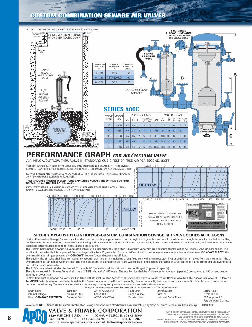
SPECIFY APCO WITH CONFIDENCE-CUSTOM COMBINATION SEWAGE AIR VALVE SERIES 400C CCSAVCustom Combination Sewage Air Valve shall be dual function; venting large volumes of air through the large orifice and small pockets of air through the small orifice before shuttingoff. Thereafter, while pressurized, pockets of air collecting, will be vented through the small orifice automatically. Should vacuum develop in the force main, both orifices shall be open,permitting large volumes of air to re-enter, to break the vacuum.The Custom Combination Sewage Air Valve shall consist of an independent large orifice Air/Vacuum Valve with an independent small orifice Air Release Valve side connected. Thesmall orifice air valve shall be separated from the large orifice by a 2” gate valve. The large orifice air valve shall incorporate one upper float and one lower CONCAVE FLOAT*; there-by maintaining an air gap between the CONCAVE* bottom float and upper shut-off float.The small orifice air valve shall have an internal compound lever mechanism including a long float stem with a stainless steel float threaded on, 11” away from the mechanism; there-by maintaining an air gap between the float and the mechanism. The air gaps shall retard waste solids from clogging the upper shut-off float of the large orifice and the lever mecha-nism of the small orifice valve.The Air/Vacuum Valve inlet shall be flanged 6” through 14”. The outlet shall be plain with hood or flanged (Engineer to specify).The side connected Air Release Valve shall have a 2” NPT inlet and 1⁄2” NPT outlet. The small orifice shall be 1⁄4” diameter for operating (opening) pressure up to 150 psi and ventingcapacity of 90 CFFAM.Custom Combination Sewage Air Valve shall be fitted with (2) inlet isolation Valves: 2” all Bronze gate valve to isolate the Air Release Valve from the Air/Vacuum Valve. (1) 6” through14” APCO Butterfly Valve or Gate Valve to isolate the Air/Vacuum Valve from the force main. (2) blow off valves, (2) flush valves and minimum of 5’ rubber hose with quick discon-nects for back-flushing. The manufacturer shall certify venting capacity and provide maintenance manuals with each valve.
Materials of construction shall be certified to the following A.S.T.M. specificationsBody, cover Cast iron ASTM A126 GR.B Float Stem Stainless Steel Series T300 Internal linkage Stainless Steel Series T300 Needle & seat Buna-N Nitrile RubberFloat* CONCAVE PATENTED Stainless Steel ASTM A240 T304 Exterior paint Universal Metal Primer FDA Approved for
Potable Water Contact
Valve to be APCO Series 400C Custom Combination Sewage Air Valve with attachments, as manufactured by Valve & Primer Corporation, Schaumburg, IL 60193-4599
PERFORMANCE GRAPH FOR AIR/VACUUM VALVEAIR INFLOW/OUTFLOW THRU VALVE IN STANDARD CUBIC FEET OF FREE AIR PER SECOND, (SCFS)
TEST CONDUCTED BY: PHILLIP PETROLEUM COMPANY ENGINEERING DEPARTMENT — TEST DIVISION EDMOND PLANT FEB. 2, 1961 SOUTHERN RESEARCH INSTITUTE BIRMINGHAM, ALABAMA MAY 8, 1959
CURVES SHOWN ARE ACTUAL FLOW CAPACITIES AT 14.7 PSI BAROMETRIC PRESSURE AND AT70°F TEMPERATURE BASE ON ACTUAL TEST.
THESE FIGURES ARE NOT MERELY FLOW CAPACITIES ACROSS THE ORIFICE, BUT FLOWCAPACITIES ACROSS THE ENTIRE VALVE.
IN THE TEST SET-UP, AIR APPROACH VELOCITY IS NEGLIGIBLE THEREFORE, ACTUAL FLOWCAPACITY EXCEEDS THE VALUES SHOWN ON THE CHART.
VALVE SIZE 1⁄2” 1” 2” 3” 4” 6” 8” 10”12”14”
0.2 0.3 0.4 0.6 0.81 2 3 4 5 6 78 10 20 30 4050 100 200 300 5001
2
3
4
5
6
6
5
4
3
2
1PRES
S. D
IFF.
AC
RO
SS V
ALV
E IN
PSI
VAC
UU
M A
CR
OSS
VA
LVE
IN P
SI
OUTFLOW
14”12” 10” 8” 6” 4” 3” 2” 1” 1⁄2” VALVE SIZE
500 300 200 100 5040 30 20 10 8 7 6 5 4 3 2 1 0.8 0.6 0.4 0.3 0.2
INFLOW
TYPICAL PIT INSTALLATION DETAIL FOR SEWAGE AIR VALVE
VALVESIZE
MODELNO.
125 LB. CLASS 250 LB. CLASS
A B C A B CFLG. HOLESNO. DIA.
FLG. HOLESNO. DIA.WT.
6” 406C 361⁄2 29 12 8 7⁄8 265 371⁄2 29 12 12 7⁄8
8” 408C 40 33 12 8 7⁄8 515 41 33 12 12 1
10” 410C 45 35 12 12 1 660 461⁄4 35 12 16 11⁄8
12” 412C 531⁄2 40 12 12 1 825 543⁄4 40 12 16 11⁄4
14” 414C 571⁄4 44 15 12 11⁄8 1035 583⁄4 44 15 20 11⁄4
CUSTOM COMBINATION SEWAGE AIR VALVES
INLET
SEWAGEAIR RELEASE
VALVE
SEAT DETAILAIR/VACUUM VALVE
125 LB: 14” & LARGER250 LB: ALL SIZES
ISOLATIONBUTTERFLY VALVE
CONCAVE FLOAT*PATENTED
SERIES 400C
REINFORCEDCONCRETE
PIPE
8”MIN.
1-8”TYP.
2” MIN.
8”TYP
3’ - 0”I.D.
PRECASTCONCRETE
(DEPTH ASREQUIRED)
APCOSEWAGE
AIR RELEASEVALVES
6”MIN.
FINISHEDGRADE
30” DIA. VENTED M H FRAMEAND COVER (BOLTED DOWN)
CONCRETEFOOTING
2” NPT.
CONCRETEFOOTING
COMPACTED GRAVEL BEDDING
FOR ACCURATE SIZE SELECTION
USE APCO AIR VALVE COMPUTER
SOFTWARE. APSLIDE AVAILABLE
UPON REQUEST
OPERATINGPRESSURE
PSI
ORIFICEDIAMETER
IN.
VENTINGCAPACITY
CFFAM
0 - 50 5/16 55
0 - 150 1⁄4 STANDARD 90
0 - 300 5/32 25
CUSTOM COMBINATION SEWAGE AIR VALVES
8