Embed Size (px)
Citation preview

Setup-Software DRIVE.EXE
for
AX2000
Description of parameters and functions
Edition 07/03

Previously published editions :
Edition Notes
06/00 First edition
09/01 Contents completely new, identical to online-help
10/02Valid from Software Version 4.90, Bode plot description, position output, external trajectory, oscilloscope, various
minor corrections
07/03 new motion task types, Graphical Motion Tasking added, valid from software version 5.00
PC-AT is a registered trademark of International Business Machines Corp.
MS-DOS is a registered trademark of Microsoft Corp.
WINDOWS is a registered trademark of Microsoft Corp.
HIPERFACE is a registered trademark of Max Stegmann GmbH
EnDat is a registered trademark of Dr.Johannes Heidenhain GmbH
Technical changes which improve the performance of the equipment may be made without prior notice!Printed in the Federal Republ ic of Germany 07/03
Al l r ights reserved. No part of th is work may be reproduced in any form (by pr int ing, photocopying, microf i lmor any other method) or stored, processed, copied or distr ibuted by electronic means without the wri t ten
permission of Beckhoff .

Setup Software 3
BECKHOFF 07/03 Contents
1 General Information . . . . . . . . . . . . . . . . . . . . . . . . . . . . . . . . . . . . . . . . . . . . . . . . . . . . . . 5
1.1 Contents . . . . . . . . . . . . . . . . . . . . . . . . . . . . . . . . . . . . . . . . . . . . . . . . . . . . . . . . . . . . . . . . . . . . . . . . . . . . . . . . . . . . . . . . . . 5
1.2 Symbols used . . . . . . . . . . . . . . . . . . . . . . . . . . . . . . . . . . . . . . . . . . . . . . . . . . . . . . . . . . . . . . . . . . . . . . . . . . . . . . . . . . . . . . 5
1.3 Prescribed use ("Use as directed") . . . . . . . . . . . . . . . . . . . . . . . . . . . . . . . . . . . . . . . . . . . . . . . . . . . . . . . . . . . . . . . . . . . . . . 6
1.4 Abbreviations used . . . . . . . . . . . . . . . . . . . . . . . . . . . . . . . . . . . . . . . . . . . . . . . . . . . . . . . . . . . . . . . . . . . . . . . . . . . . . . . . . . 7
2 Product Overview . . . . . . . . . . . . . . . . . . . . . . . . . . . . . . . . . . . . . . . . . . . . . . . . . . . . . . . 8
3 Servo System Overview . . . . . . . . . . . . . . . . . . . . . . . . . . . . . . . . . . . . . . . . . . . . . . . . . . . . 9
3.1 Feedback Device . . . . . . . . . . . . . . . . . . . . . . . . . . . . . . . . . . . . . . . . . . . . . . . . . . . . . . . . . . . . . . . . . . . . . . . . . . . . . . . . . . 10
3.2 The Motion Profile. . . . . . . . . . . . . . . . . . . . . . . . . . . . . . . . . . . . . . . . . . . . . . . . . . . . . . . . . . . . . . . . . . . . . . . . . . . . . . . . . . 10
3.3 Limits and Ranges of Operation . . . . . . . . . . . . . . . . . . . . . . . . . . . . . . . . . . . . . . . . . . . . . . . . . . . . . . . . . . . . . . . . . . . . . . . 11
3.4 Acceleration and Deceleration . . . . . . . . . . . . . . . . . . . . . . . . . . . . . . . . . . . . . . . . . . . . . . . . . . . . . . . . . . . . . . . . . . . . . . . . 11
4 Getting Started . . . . . . . . . . . . . . . . . . . . . . . . . . . . . . . . . . . . . . . . . . . . . . . . . . . . . . . . 12
4.1 Operating systems . . . . . . . . . . . . . . . . . . . . . . . . . . . . . . . . . . . . . . . . . . . . . . . . . . . . . . . . . . . . . . . . . . . . . . . . . . . . . . . . . 12
4.2 Software description . . . . . . . . . . . . . . . . . . . . . . . . . . . . . . . . . . . . . . . . . . . . . . . . . . . . . . . . . . . . . . . . . . . . . . . . . . . . . . . . 12
4.3 Hardware requirements . . . . . . . . . . . . . . . . . . . . . . . . . . . . . . . . . . . . . . . . . . . . . . . . . . . . . . . . . . . . . . . . . . . . . . . . . . . . . 12
4.4 RS232 interface, PC connection (X6) . . . . . . . . . . . . . . . . . . . . . . . . . . . . . . . . . . . . . . . . . . . . . . . . . . . . . . . . . . . . . . . . . . . 13
4.5 Installation under WINDOWS 95(c) / 98 / 2000 / ME / XP / NT . . . . . . . . . . . . . . . . . . . . . . . . . . . . . . . . . . . . . . . . . . . . . . . 14
4.6 Operation . . . . . . . . . . . . . . . . . . . . . . . . . . . . . . . . . . . . . . . . . . . . . . . . . . . . . . . . . . . . . . . . . . . . . . . . . . . . . . . . . . . . . . . . 14
4.7 Function keys . . . . . . . . . . . . . . . . . . . . . . . . . . . . . . . . . . . . . . . . . . . . . . . . . . . . . . . . . . . . . . . . . . . . . . . . . . . . . . . . . . . . . 15
5 Axis Commissioning Checklist Procedures . . . . . . . . . . . . . . . . . . . . . . . . . . . . . . . . . . . . . . . . . 16
5.1 General . . . . . . . . . . . . . . . . . . . . . . . . . . . . . . . . . . . . . . . . . . . . . . . . . . . . . . . . . . . . . . . . . . . . . . . . . . . . . . . . . . . . . . . . . . 16
5.2 Parameterization. . . . . . . . . . . . . . . . . . . . . . . . . . . . . . . . . . . . . . . . . . . . . . . . . . . . . . . . . . . . . . . . . . . . . . . . . . . . . . . . . . . 16
5.3 Switch on auxiliary supply. . . . . . . . . . . . . . . . . . . . . . . . . . . . . . . . . . . . . . . . . . . . . . . . . . . . . . . . . . . . . . . . . . . . . . . . . . . . 16
5.4 Basic setting . . . . . . . . . . . . . . . . . . . . . . . . . . . . . . . . . . . . . . . . . . . . . . . . . . . . . . . . . . . . . . . . . . . . . . . . . . . . . . . . . . . . . . 17
5.5 Optimization of the control loops . . . . . . . . . . . . . . . . . . . . . . . . . . . . . . . . . . . . . . . . . . . . . . . . . . . . . . . . . . . . . . . . . . . . . . 19
5.6 Optimizing the current controller . . . . . . . . . . . . . . . . . . . . . . . . . . . . . . . . . . . . . . . . . . . . . . . . . . . . . . . . . . . . . . . . . . . . . . . 19
5.7 Optimizing the speed controller . . . . . . . . . . . . . . . . . . . . . . . . . . . . . . . . . . . . . . . . . . . . . . . . . . . . . . . . . . . . . . . . . . . . . . . 20
5.8 Optimizing the position controller . . . . . . . . . . . . . . . . . . . . . . . . . . . . . . . . . . . . . . . . . . . . . . . . . . . . . . . . . . . . . . . . . . . . . . 21
6 Screen layout . . . . . . . . . . . . . . . . . . . . . . . . . . . . . . . . . . . . . . . . . . . . . . . . . . . . . . . . . 23
7 Screen page "Communication" . . . . . . . . . . . . . . . . . . . . . . . . . . . . . . . . . . . . . . . . . . . . . . . . 25
8 Screen page "Amplifier" . . . . . . . . . . . . . . . . . . . . . . . . . . . . . . . . . . . . . . . . . . . . . . . . . . . 26
9 Slot . . . . . . . . . . . . . . . . . . . . . . . . . . . . . . . . . . . . . . . . . . . . . . . . . . . . . . . . . . . . . . 28
10 Screen page "Basic Setup". . . . . . . . . . . . . . . . . . . . . . . . . . . . . . . . . . . . . . . . . . . . . . . . . . 29
11 Screen page "Motor" synchronous . . . . . . . . . . . . . . . . . . . . . . . . . . . . . . . . . . . . . . . . . . . . . . 32
12 Screen page "Motor" asynchronous . . . . . . . . . . . . . . . . . . . . . . . . . . . . . . . . . . . . . . . . . . . . . 34
13 Screen page "Feedback" . . . . . . . . . . . . . . . . . . . . . . . . . . . . . . . . . . . . . . . . . . . . . . . . . . . 36
14 Screen page "Encoder". . . . . . . . . . . . . . . . . . . . . . . . . . . . . . . . . . . . . . . . . . . . . . . . . . . . 38
15 Screen page "Analog I/O" . . . . . . . . . . . . . . . . . . . . . . . . . . . . . . . . . . . . . . . . . . . . . . . . . . 40
15.1 Analog Inputs AN IN1 / AN IN 2 . . . . . . . . . . . . . . . . . . . . . . . . . . . . . . . . . . . . . . . . . . . . . . . . . . . . . . . . . . . . . . . . . . . . . . . 40
15.2 Analog Outputs AN OUT1 / AN OUT2 . . . . . . . . . . . . . . . . . . . . . . . . . . . . . . . . . . . . . . . . . . . . . . . . . . . . . . . . . . . . . . . . . . 43
16 Screen page "Digital I/O" . . . . . . . . . . . . . . . . . . . . . . . . . . . . . . . . . . . . . . . . . . . . . . . . . . . 44
16.1 Digital inputs DIGITAL-IN1 / DIGITAL-IN2 / PSTOP / NSTOP . . . . . . . . . . . . . . . . . . . . . . . . . . . . . . . . . . . . . . . . . . . . . . . . 44
16.1.1 Description of the digital inputs . . . . . . . . . . . . . . . . . . . . . . . . . . . . . . . . . . . . . . . . . . . . . . . . . . . . . . . . . . . . . . . . . . . . 45
16.2 Digital outputs DIGITAL-OUT1 / DIGITAL-OUT2 . . . . . . . . . . . . . . . . . . . . . . . . . . . . . . . . . . . . . . . . . . . . . . . . . . . . . . . . . . 49
16.2.1 Description of the digital outputs . . . . . . . . . . . . . . . . . . . . . . . . . . . . . . . . . . . . . . . . . . . . . . . . . . . . . . . . . . . . . . . . . . . 50
17 Screen page "Current" . . . . . . . . . . . . . . . . . . . . . . . . . . . . . . . . . . . . . . . . . . . . . . . . . . . . 52
18 Screen page "Speed". . . . . . . . . . . . . . . . . . . . . . . . . . . . . . . . . . . . . . . . . . . . . . . . . . . . . 53
19 Screen page "Position" (PI) . . . . . . . . . . . . . . . . . . . . . . . . . . . . . . . . . . . . . . . . . . . . . . . . . 55
20 Screen page "Position" (P) . . . . . . . . . . . . . . . . . . . . . . . . . . . . . . . . . . . . . . . . . . . . . . . . . . 56
Contents

4 Setup Software
Contents 07/03 BECKHOFF
21 Screen page "Homing" . . . . . . . . . . . . . . . . . . . . . . . . . . . . . . . . . . . . . . . . . . . . . . . . . . . . 57
21.1 Homing 1. . . . . . . . . . . . . . . . . . . . . . . . . . . . . . . . . . . . . . . . . . . . . . . . . . . . . . . . . . . . . . . . . . . . . . . . . . . . . . . . . . . . . . . . . 59
21.2 Homing 2. . . . . . . . . . . . . . . . . . . . . . . . . . . . . . . . . . . . . . . . . . . . . . . . . . . . . . . . . . . . . . . . . . . . . . . . . . . . . . . . . . . . . . . . . 60
21.3 Homing 3. . . . . . . . . . . . . . . . . . . . . . . . . . . . . . . . . . . . . . . . . . . . . . . . . . . . . . . . . . . . . . . . . . . . . . . . . . . . . . . . . . . . . . . . . 61
21.4 Homing 4. . . . . . . . . . . . . . . . . . . . . . . . . . . . . . . . . . . . . . . . . . . . . . . . . . . . . . . . . . . . . . . . . . . . . . . . . . . . . . . . . . . . . . . . . 62
21.5 Homing 5. . . . . . . . . . . . . . . . . . . . . . . . . . . . . . . . . . . . . . . . . . . . . . . . . . . . . . . . . . . . . . . . . . . . . . . . . . . . . . . . . . . . . . . . . 63
21.6 Homing 7. . . . . . . . . . . . . . . . . . . . . . . . . . . . . . . . . . . . . . . . . . . . . . . . . . . . . . . . . . . . . . . . . . . . . . . . . . . . . . . . . . . . . . . . . 64
21.7 Jog mode . . . . . . . . . . . . . . . . . . . . . . . . . . . . . . . . . . . . . . . . . . . . . . . . . . . . . . . . . . . . . . . . . . . . . . . . . . . . . . . . . . . . . . . . 65
22 Screen page "Position Data" . . . . . . . . . . . . . . . . . . . . . . . . . . . . . . . . . . . . . . . . . . . . . . . . . 66
23 Screen page "Motion task parameters" . . . . . . . . . . . . . . . . . . . . . . . . . . . . . . . . . . . . . . . . . . . 70
23.1 Type Motion . . . . . . . . . . . . . . . . . . . . . . . . . . . . . . . . . . . . . . . . . . . . . . . . . . . . . . . . . . . . . . . . . . . . . . . . . . . . . . . . . . . . . . 71
23.2 Type Delay . . . . . . . . . . . . . . . . . . . . . . . . . . . . . . . . . . . . . . . . . . . . . . . . . . . . . . . . . . . . . . . . . . . . . . . . . . . . . . . . . . . . . . . 73
23.3 Type Comparison tests . . . . . . . . . . . . . . . . . . . . . . . . . . . . . . . . . . . . . . . . . . . . . . . . . . . . . . . . . . . . . . . . . . . . . . . . . . . . . . 74
23.4 Type Modify parameter . . . . . . . . . . . . . . . . . . . . . . . . . . . . . . . . . . . . . . . . . . . . . . . . . . . . . . . . . . . . . . . . . . . . . . . . . . . . . . 75
23.5 Type Initialize loop . . . . . . . . . . . . . . . . . . . . . . . . . . . . . . . . . . . . . . . . . . . . . . . . . . . . . . . . . . . . . . . . . . . . . . . . . . . . . . . . . 76
23.6 Type Decrement counter . . . . . . . . . . . . . . . . . . . . . . . . . . . . . . . . . . . . . . . . . . . . . . . . . . . . . . . . . . . . . . . . . . . . . . . . . . . . 76
23.7 Type Loop. . . . . . . . . . . . . . . . . . . . . . . . . . . . . . . . . . . . . . . . . . . . . . . . . . . . . . . . . . . . . . . . . . . . . . . . . . . . . . . . . . . . . . . . 77
23.8 Type Jog . . . . . . . . . . . . . . . . . . . . . . . . . . . . . . . . . . . . . . . . . . . . . . . . . . . . . . . . . . . . . . . . . . . . . . . . . . . . . . . . . . . . . . . . . 77
23.9 Type go to Home / Index / Registration + Offset. . . . . . . . . . . . . . . . . . . . . . . . . . . . . . . . . . . . . . . . . . . . . . . . . . . . . . . . . . . 77
24 Screen page "Gearing" . . . . . . . . . . . . . . . . . . . . . . . . . . . . . . . . . . . . . . . . . . . . . . . . . . . . 79
25 Screen page "Drive status" . . . . . . . . . . . . . . . . . . . . . . . . . . . . . . . . . . . . . . . . . . . . . . . . . . 80
26 Screen page "Actual values" . . . . . . . . . . . . . . . . . . . . . . . . . . . . . . . . . . . . . . . . . . . . . . . . . 81
27 Screen page "Oscilloscope" . . . . . . . . . . . . . . . . . . . . . . . . . . . . . . . . . . . . . . . . . . . . . . . . . 82
28 Screen page "Input Service Parameters" . . . . . . . . . . . . . . . . . . . . . . . . . . . . . . . . . . . . . . . . . . 84
29 Screen page "Bode Plot" . . . . . . . . . . . . . . . . . . . . . . . . . . . . . . . . . . . . . . . . . . . . . . . . . . . 85
30 Screen page "Terminal" . . . . . . . . . . . . . . . . . . . . . . . . . . . . . . . . . . . . . . . . . . . . . . . . . . . 86
31 Screen page "PROFIBUS" . . . . . . . . . . . . . . . . . . . . . . . . . . . . . . . . . . . . . . . . . . . . . . . . . . 87
32 Screen Page "PROFIBUS instrument control" . . . . . . . . . . . . . . . . . . . . . . . . . . . . . . . . . . . . . . . . 88
33 Screen Page "SERCOS" . . . . . . . . . . . . . . . . . . . . . . . . . . . . . . . . . . . . . . . . . . . . . . . . . . . 90
34 Screen Page "SERCOS SERVICE" . . . . . . . . . . . . . . . . . . . . . . . . . . . . . . . . . . . . . . . . . . . . . 91
35 Screen page "I/O expansion". . . . . . . . . . . . . . . . . . . . . . . . . . . . . . . . . . . . . . . . . . . . . . . . . 92
36 Error and warning messages . . . . . . . . . . . . . . . . . . . . . . . . . . . . . . . . . . . . . . . . . . . . . . . . . 93
36.1 Error messages. . . . . . . . . . . . . . . . . . . . . . . . . . . . . . . . . . . . . . . . . . . . . . . . . . . . . . . . . . . . . . . . . . . . . . . . . . . . . . . . . . . . 93
36.2 Warning messages . . . . . . . . . . . . . . . . . . . . . . . . . . . . . . . . . . . . . . . . . . . . . . . . . . . . . . . . . . . . . . . . . . . . . . . . . . . . . . . . . 94
37 Trouble-Shooting . . . . . . . . . . . . . . . . . . . . . . . . . . . . . . . . . . . . . . . . . . . . . . . . . . . . . . . 95
38 Related Documents . . . . . . . . . . . . . . . . . . . . . . . . . . . . . . . . . . . . . . . . . . . . . . . . . . . . . 96
39 Glossary . . . . . . . . . . . . . . . . . . . . . . . . . . . . . . . . . . . . . . . . . . . . . . . . . . . . . . . . . . . 97
40 Motor Numbers . . . . . . . . . . . . . . . . . . . . . . . . . . . . . . . . . . . . . . . . . . . . . . . . . . . . . . . . 98
41 Index . . . . . . . . . . . . . . . . . . . . . . . . . . . . . . . . . . . . . . . . . . . . . . . . . . . . . . . . . . . . 100
Contents

1 General Information
This help system explains the installation and operation of the setup software DRIVE.EXE for digital servo
amplifiers.
1.1 Contents
General
Product overview Axis commissioning checklist procedures
Servo System Overview Error messages and warnings
Related Documents Trouble-Shooting
Dialog screen layout Motor numbers
Getting started Glossar
Screen pages
Communication Position controller (PI)
Amplifier Position controller (P)
Slot Position Data
Basic Setup Homing
Synchronous motor Motion Tasks Parameters
Asynchronous motor Gearing
Feedback Drive Status
Encoder Emulation Actual values
Digital I/O Terminal
Analog I/O PROFIBUS
Current PROFIBUS instrument control
Speed SERCOS
Oszilloscope SERCOS Service
Input Service Parameters I/O-Extension
Bode Plot
1.2 Symbols used
danger to personnel
from electricity
and its effects
general warning
general instructions
mechanical hazard
Setup Software 5
BECKHOFF 07/03 General Information
1.3 Prescribed use ("Use as directed")
Setup Software
The setup software is intended to be used for altering or storing the operational parameters for the digital servo
amplifiers. The servo amplifier that is connected is commissioned with the aid of the software - whereby the
drive can be directly controlled by the setup and service functions.
The characteristic nature of a PC mean that these functions are not functionally safe without further measures.
A PC-program might be unexpectedly disturbed or stopped, so that in the event of a malfunction any
movements that have already been initiated cannot be stopped from the PC.
The manufacturer of the machine must carry out a hazard analysis for the machine,and is responsible for the functional, mechanical and personnel safety aspects of themachine. This applies especially to the initiation of movements with the aid offunctions in the commissioning software.Only personnel who have extensive knowledge in the fields of drive technology andcontrol technology are permitted to carry out online parameter setting of a drive thatis running.Sets of data that are stored on data media are not safe from undesirable alterationby third parties. So after you have loaded a set of data, you must check all theparameters before enabling the servo amplifier.
Servo amplifier
The BTB/RTO contact must be wired into the safety loop of the system. The safety loop, and the Stop and
Emergency Stop functions must fulfill the requirements of EN60204, EN292 and VDI 2853.
The servo amplifiers are components which are built into electrical equipment or machines, and can only be
commissioned as integral components of such equipment.
The servo amplifier is to be used only on earthed three-phase industrial mains supply networks (TN-system,
TT-system with earthed neutral point). The servo amplifiers must not be operated directly on power supply
networks >230V without an earth (ground) or with an asymmetrical earth (ground).
Connection to different mains supply networks is only admitted with an additional isolating transformer
(see installation manual page 14).
Periodic overvoltages between outer conductor (L1, L2, L3) and housing of the servo amplifier may not exceed
1000V (peak value). Transient overvoltages (< 50µs) between the outer conductors may not exceed 1000V.
Transient overvoltages (< 50µs) between outer conductors and housing may not exceed 2000V.
If the servo amplifiers are used in residential areas, or in business or commercial premises, then additional filter
measures must be implemented by the user.
The servo amplifier is only intended to drive specific brushless synchronous servomotors, with closed-loop
control of torque, speed and/or position. The rated voltage of the motors must be at least as high as the DC-link
voltage of the servo amplifier.
The servo amplifiers may only be operated in a closed switchgear cabinet, taking into account the ambient
conditions defined in the installation manual.
Option -AS-, restart lock for personnel safety
The -AS- restart lock is exclusively intended to provide safety for personnel, by preventing the restart of a
system. To achieve this personnel safety, the wiring of the safety circuits must meet the safety requirements of
EN60204, EN292 and EN954-1
The -AS- restart lock must only be activated,
— when the motor is no longer rotating (setpoint = 0V, speed = 0rpm, enable = 0V).
Drives with a suspended load must have an additional safe mechanical blocking
(e.g. by a motor-holding brake).
— when the monitoring contacts (KSO1/2 and BTB/RTO) for all servo amplifiers are
wired into the control signal loop (to recognize a cable break).
The -AS- restart lock may only be controlled by a CNC if the control of the internal safety relay is arranged for
redundant monitoring.
The -AS- restart lock must not be used if the drive is to be made inactive for the following reasons:
1. - cleaning, maintenance and repair operations
- long inoperative periods
In such cases, the entire system should be disconnected from the supply by the personnel,
and secured (main switch).
2. - emergency-stop situations
In an emergency-stop situation, the main contactor is switched off
(by the emergency-stop button or the BTB-contact in the safety circuit).
6 Setup Software
General Information 07/03 BECKHOFF

1.4 Abbreviations used
The abbreviations used are explained in the table below.
Abbrev. Meaning
AGND Analog ground
AS Restart Lock, option
BTB/RTO Ready to operate
CAN Fieldbus (CANopen)
CE Communité Europeenne (EC)
CLK Clock
COM Serial interface for a PC
DGND Digital ground
DIN Deutsches Institut für Normung
Disk Magnetic storage (diskette, hard disk)
EEPROM Electrically erasable/programmable memory
EMV Electromagnetic compatibility
EN European standard
IEC International Electrotechnical Commission
ISO International Standardization Organization
LED Light-emitting diode
MB Megabyte
MS-DOS Operating system for a PC
NI Zero pulse/mark
NSTOP Limit-switch input for CCW rotation
PC Personal Computer
PGND Ground for the interface
PLC Programmable logic controller
PSTOP Limit-switch input for CW rotation
RAM Volatile memory
RBallast Regen resistor
RBext External regen resistor
RBint Internal regen resistor
RES Resolver
ROD Incremental encoder output
SRAM Static RAM
SSI Synchronous serial interface
UL Underwriter Laboratory
V AC Alternating (AC) voltage
V DC DC voltage
VDE Verein deutscher Elektrotechniker
XGND Ground for the 24V supply
Setup Software 7
BECKHOFF 07/03 General Information

2 Product Overview
What is DRIVE.EXE?
DRIVE.EXE is an axis commissioning tool for both single-axis and multi-axis motion control applications. With
its graphical user interface and Windows dialogues, DRIVE.EXE provides an easy point-and-click method for
configuring servo amplifiers
Single-Axis Motion Control
In a single axis system, DRIVE.EXE runs on a programming unit (PC) connected to one servo drive. The
communication is established via the RS232 interface.
Multi-Axis Motion Control
In a multi axis system, DRIVE.EXE runs on a programming unit (PC) connected to one servo drive. The
communication with the first servo drive is established via the RS232 interface. The other servo drives are
connected to the first servo drive by a special cable (Y-adapter) at the built in CAN-bus. Thereby you can
communicate with several servo drives without changing connections.
Tuning Your Axis with DRIVE.EXE
During the configuration process, DRIVE.EXE allows you to tune (stabilize) the servo motor for each axis
quickly and efficiently. From DRIVE.EXE, while online with an axis and its motor, you adjust servo parameter
values (such as gains and limits) and execute them immediately. While watching and listening to the motor spin,
you may use the DRIVE.EXE oscilloscope to adjust and readjust these values until the motor reaches its best
performance - optimum speed without oscillation. The changes made to the servo parameter values may be
saved to the servoamplifier or to a file.
DRIVE.EXE dialogues step you through the complete startup phase of your programming projects. All param-
eters in the servo drive can be saved to a separate file for each axis. Each drive file is a unique custom configu-
ration for that drive and can be accessed offline (not connected to the drive) or online (connected to the drive).
Please see also the axis commissioning checklist procedures.
8 Setup Software
Product Overview 07/03 BECKHOFF
3 Servo System Overview
This topic provides a quick lesson in servo system - an overview of what it is and how it works.
What is a Servo System?
A servo system essentially comprises an intelligent servo drive and a servo motor that operates with a PLC or
CNC to perform complex, specialized moves in one or more directions, or axes. These complex and specialized
moves, which are needed in the automation of industrial tasks, are collectively known as motion control.
Servo systems are applied in many different field for automation - in the motor industry, the petrol industry, the
textile industry, in packaging systems, warehousing systems and so on.
Closed Loop Servo Systems
In a servo system, feedback information - motor position and motor velocity is sent from the feedback unit of the
motor back to the servo amplifier. The servo amplifier analyses the feedback, makes adjustments as needed,
and generates new currents to bring the motor to the commanded velocity. This cycle constantly repeats itself in
a closed loop. A closed loop that controls the position of the shaft or load is called a position loop. A closed loop
that keeps the velocity of the motor on the commanded value is called a velocity loop.
Servo System Components
A servo system consists of:
Servo motor
A servo motor moves machinery in a single axis of motion.
Electrical motors are driven by magnetic fields. Motors have a stationary field generated
by the magnets of the motor and a rotating or movable field called stator winding or
armature. They operate on the principles of synchronous motors. All rotary motors have
some type of bearing that supports the rotor at each end.
Every motor has at least two magnetic motor poles, normally four or six. The servo
amplifier generates the current in the stator so that a controllable torque is available at the
shaft.
The servo motors turn (travel) in two directions - positive and negative. Two forms of
angular measurement are commonly used in motion control - degree measurement and
radian measurement, where 360 degrees constitute one revolution or 2� radians.
The servo amplifier operates with standard synchronous servo motors as well as with
direct drive motors (rotary or linear). For more information about these motors see the
motor manuals.
Motor Stabilizing
Stabilizing (tuning) the motor is a fundamental task in achieving best system performance.
To stabilize a motor, you must set up initial values for and adjust several motion param-
eters using DRIVE.EXE. These parameter settings compensate for the difference
between the actual motion and the commanded motion - getting the actual as close to the
commanded as possible, with minimal oscillation and noise. This difference is called
following error.
Load
The load is the machinery and equipment that each motor drives. It is everything
connected to the output shaft of a motor, including the shaft itself. A motor must be appro-
priately sized to its load to ensure the motor is powerful enough to carry out your
automation tasks. A servo system delivers and converts motion to a load via one or more
of the following mechanical techniques:
Direct drive
motor connected to a rotating table
Screw drive
motor connected to a lead screw carrying a slide (moving table)
Rack and pinion
motor connected to a cogwheel that moves a rack
Belt and pulleys
motor connected to rollers that move conveyor belts or chains and sprockets
Feedback device
Every closed-loop servo system needs at least one device to return feedback information
from each motor (or load) to servo drive. Depending on the feedback device, feedback is
transmitted back to the servo drive in the form of digital signals or analog signals. Two
types of feedback devices are supported:
Encoder - returns analog or digital signals (optical)
Resolver - returns analog signals (magnetical)
Servoamplifier
(servo drives)
The servo drives comprise a three-phase, power supply, and high-performance control
unit all housed in a single enclosure. The several control loops are realize totally digital in
the micro controller.
Setup Software 9
BECKHOFF 07/03 Servo System Overview

3.1 Feedback Device
Servo motors are available with these feedback units:
� RESOLVER
� ENDAT®
compatible Heidenhain encoder
� HIPERFACE®
compatible Stegmann encoder
In a closed-loop feedback system, the innermost loop is the commutation loop, which monitors the motor's rotor
and ensures that it keeps spinning. Outer loops are: Position loop, Velocity loop and Current loop
Velocity information and the velocity loop are derived from (are computed based on) position information.
The current loop is also known as a torque loop, since amplitude of the electrical current is directly proportional
to torque. Torque is force applied in an axis of rotation.
Resolvers
The servo amplifier can use single (two poles) or multi-speed (multiple poles) resolver feedback to calculate
primary position, velocity, and commutation information. A resolver can be thought of as a transformer whose
output is unique for any given shaft position (an absolute position feedback). The transformer is driven with a
sinewave reference signal. Two AC signals are returned from the resolver into the Sine and Cosine inputs. All
three of these sinewave signals are low-level and susceptible to noise.
Encoders
Encoders direct pulses of light, from a light source at the motor or load, to photo detectors through an encoded
disk. These light pulses are then converted into digital feedback information. There are two general types of
encoders - rotary and linear. Rotary (rotating disk) encoders are typically mounted to the motor shaft. Linear
encoders are typically mounted to the load.
3.2 The Motion Profile
Overview
Motion operations are universally embodied in a graph called the motion profile. Understanding and using
motion profiles to define your motion application is an important part of achieving best system performance.
The motion profile plots one or more motion operations and measures it against time.
Commanded motion
the motion that is supposed to happen ideally and precisely, without error, when the motor executes a velocity
or position command
Actual motion
the motion that really happens in the motor, when a velocity or position command is executed
Closing the Gap between Setpoint and Actual
Best system performance is achieved when you can stabilize or "dampen" the difference or "close the gap"
between the commanded motion and the actual motion. This difference is called following error. Stabilizing the
servo system means setting the relevant parameters in the servo amplifier, to get as close to the commanded
position as possible.
Basic Motion Profile Characteristics
Commanded and actual motion profile shapes have the following characteristics that are also universal to all
motion operations:
Profile Characteristic Meaning
Moving
Moving refers to the execution of a motion instruction that makes the motor
move. A motion profile's moving portion represents most of the profile - the
motion itself. The motor is considered moving for as long as the motion controller
is commanding new positions. The point at which motion stops is known as the
target position.
In Position
When a motion command stops executing, and the motor slows to within a few
counts of its target position, the motor is considered to be stopped, or "In
Position." A range of positions, typically plotted in a motion profile, represents in
position. That is, In Position is signaled when the motor gets close enough to the
target position -- within its In-Position range that you have specified, via its
parameter. An In-Position signal is often used to make sure the motor stops
before the machinery continues its operation.
10 Setup Software
Servo System Overview 07/03 BECKHOFF

3.3 Limits and Ranges of Operation
Overview
Another important task in achieving best system performance is setting certain motion limits and ranges of
operation to protect equipment from damage and to optimize operational efficiency.
Two Types of Settings
There are two types of settings for motion limits and ranges of operation:
� Fault limits
� Tolerance bands
Type of Setting Meaning
Fault limit
Fault limits are settings that signal errors when certain limits on motor movement, such as
speed and position, as well as electrical current, are exceeded. Fault limits are designed
to protect equipment from damage and can cause the drive and motor to shut down.
For example, every motion control system has hardware limit switches, which are used in
the position loop to set a limit on how far the actual motor position can deviate from the
commanded position before a fault is signaled. You may also program software limits via
DRIVE.EXE parameters. The difference, or gap, between commanded position and
actual position is known as following error. Such a limit protects against motor runaway
and stalling.
Tolerance band
Tolerance bands are set and specify the safe, efficient physical ranges for the equipment.
Some of these tolerance bands do the following:
— In the current loop, set a limit on the amount of electrical current to the drive and
motor. This protects the motor from damage that would be caused by excessive
current.
— In the position loop, place a limit on how far the motor can travel in a positive or
negative direction.
— Set a range of positions that are considered to be In Position. That is, this range
specifies how far the motor can deviate from its commanded position and still be
considered in the correct position.
3.4 Acceleration and Deceleration
Overview
If the servo amplifier is operated with motion tasks under position control, different acceleration/deceleration
profiles can be chosen. It depends on the mechanical structure of the machine and the required dynamical
quality, which profile should be chosen. If the machine tends to sway (e.g. robot arm), sine² would be the best
choice. Here the torque is altered linear and the velocity characteristic becomes square. This reduces the
excitation to sway. Disadvantage of this profile is the double up of the acceleration/deceleration time.
If the machine is mechanically stiff and there are high requirements in dynamics, the linear profile should be
chosen. This leads to a torque step at the beginning and the end of each acceleration/deceleration ramp.
Two Types of Acceleration and Deceleration
The following table describes the two fundamental acceleration and deceleration types, linear and square.
A motion profile may accommodate a combination of these two types.
Accel / Decel Type Description
LinearLinear is a rate of acceleration and deceleration that theoretically represents a steady
speed-up and slow-down.
sine²
To limit any jolting, the drive is accelerated/decelerated within the acceleration time
along an acceleration ramp without any discontinuities. The resulting speed character-
istic corresponds to a sine² curve.
Setup Software 11
BECKHOFF 07/03 Servo System Overview

4 Getting Started
4.1 Operating systems
WINDOWS 95(c) / WINDOWS 98 / WINDOWS 2000 / WINDOWS ME / WINDOWS XP / WINDOWS NT
DRIVE.EXE runs under WINDOWS 95(c) / 98 / ME / XP / 2000 or WINDOWS NT 4.0 (service release 3 or
higher). The HTML Help system is not available under WINDOWS 95a and 95b without further updates. In this
case, an update is required for Internet Explorer to Version 4.01 (Service Pack 1) or higher.
DOS, OS2, WINDOWS 3.xx, Unix, Linux
DRIVE.EXE will not run under DOS, OS2, Windows 3.xx, Unix or Linux.
Emergency operation is possible with an ASCII terminal-emulation (no user interface).
Interface-settings: 9600 baud, 8 bit, 1 stop bit, no parity, no handshake
4.2 Software description
The servo amplifiers must be adapted to the conditions in your machine. In most cases you won’t carry out the
parameterization on the amplifier itself, but on a PC, with the aid of the setup software. The PC is connected to
the servo amplifier by a null-modem cable (serial). The setup software establishes the communication between
the PC and the servo amplifier.
With very little effort, you can alter parameters and instantly see the effect on the drive, since there is a
continuous (online) connection to the amplifier. Important process values / actual values are simultaneously
read out from the amplifier and displayed on the monitor of the PC (oscilloscope functions).
Any interface modules (expansion cards) that are built into the servo amplifier will be recognized automatically.
You can store sets of data on a data medium (archiving) and load them again. The data set that is in use at the
moment can be printed out.
We provide you with default sets of motor-specific data for reasonable combinations of servo amplifier + motor.
In most applications you will be able to commission your drive without any problems, just by using these default
values.
4.3 Hardware requirements
The PC interface (X6, RS232) of the servo amplifier is connected to the serial interface of the PC via a
null-modem cable (not a null-modem link cable).
Disconnect and connect the cable only while all the supply voltages are switched off(amplifier and PC).
The interface in the servo amplifier is electrically isolated by optocouplers, and is at the same potential as the
CANopen interface.
Minimum specification for the PC:
Processor 80486 or higher
Operating system WINDOWS 95(c) / 98 / ME / 2000 / XP / NT4.x
Graphics card Windows-compatible, color
DrivesHard disk (5 MB free space)
CD-ROM drive
Main memory 8MB minimum
Interfaceone free serial interface (COM1:, COM2:, COM3: or COM4:)
This interface must not be used by any other software (driver or similar).
12 Setup Software
Getting Started 07/03 BECKHOFF

4.4 RS232 interface, PC connection (X6)
You can carry out the setting up of the parameters for operating, position control, and motion-blocks, by using
the setup software on an ordinary personal computer (PC).
Connect the PC interface (X6) of the servo amplifier to the serial interface of the PC via a 3-core null-modem
cable (do not use a null-modem link cable). Do this only while the supply voltages are switched off.
The interface is electrically isolated by optocouplers, and is at the same potential as the CANopen interface.
The interface is selected in the setup software.
Interface cable between the PC and the servo amplifier
(View: looking at the built-in SubD connector, i.e. the solder side of the SubD plug on the cable)
Setup Software 13
BECKHOFF 07/03 Getting Started

4.5 Installation under WINDOWS 95(c) / 98 / 2000 / ME / XP / NT
You can install the setup software directly from the enclosed CD-ROM (call up SETUP.EXE).
Connection to the serial interface of the PC:
Connect the interface cable between the serial interface of your PC and the PC-interface (X6) of the amplifier.
Switch-on:
Switch on your PC-AT and the monitor.
When the boot phase is finished, the Windows user-interface will appear on the screen.
Installation:
Click on START (taskbar), then on Run.
Enter the program call: a:\setup.exe (where a: is the correct drive letter).
Click on OK and follow the instructions.
Setting up the graphics card (font size)
Note that the screen resolution must at least be 800x600 pixel.
Click on the desktop with the right mouse button. The dialogue window "Properties" will appear. Select the file
card "Settings". Set the Font size to "Small Fonts". Follow the instructions provided by the system.
4.6 Operation
The setup software is basically used in the same way as other Windows programs.
Use a decimal point as the decimal symbol, do not use a comma.
Please note that, after an alteration in a parameter on a screen page, you must first click on APPLY, so that the
parameter is transferred to the RAM of the servo amplifier. Only then you should leave the page. If a reset of the
servo amplifier is necessary to activate a function, this will be recognized by the setup software, which will make
a reset after a software confirmation request.
The currently valid data set must be saved in the EEPROM of the servo amplifier, in order to be permanently
stored. So execute the Save Data to EEPROM function on the "Amplifier" page before you switch off the servo
amplifier or quit processing the data set.
Values appearing in red on the screen pages designate parameters that are intended for advanced users
only.
14 Setup Software
Getting Started 07/03 BECKHOFF

4.7 Function keys
Function key Function Comment
F1 Help Contextual help
F2 reserved reserved
F3 reserved reserved
F4 Jog ModeStarts the Jog Mode. The drive operates under the parameters that
are pre-selected on the "Homing" page while the F4 key is pressed.
F5 DC
The drive operates under the parameters that are pre-selected on the
"Oscilloscope/Service" pages.
F6 Speed
F7 Torque
F8 Reversing
F9 Stop (OFF)
Brakes off the drive movement. The response of the drive varies
according to the operating mode that is valid at the moment:
OPMODE=0
the drive brakes along the preset braking ramp for the speed control
loop (DEC)
OPMODE=2
the drive coasts down
OPMODE=8
breaks off the present motion task. The drive brakes along the braking
ramp that is defined in the motion task.
F12 Disable Software disable
Shift F12 Enable Software enable
Stopping the axis by using F9 or F12 does not ensure personal safety unless furthermeasures are implemented. For safety, operate the ENABLE signal for the amplifierthrough a button that has to be confirmed, and ensure that the EMERGENCY STOPfunction is active for this axis.
Setup Software 15
BECKHOFF 07/03 Getting Started

5 Axis Commissioning Checklist Procedures
5.1 General
This chapter provides you with strategies for the commissioning of the digital servo amplifier and the optimi-
zation of its control loops.
These strategies cannot be universally valid. You may have to develop your own strategy, depending the speci-
fication of your machine.
However, the sequences that are presented here will help you to understand the basic methodology.
5.2 Parameterization
The manufacturer of the machine must create a hazard analysis for the machine,and is responsible for the machine with regard to functional, mechanical andpersonnel safety. This applies particularly to the initiation of movements with the aidof commissioning-software functions.The commissioning of the servo drive with the aid of Setup software functions isonly permitted in combination with an interlock device according to EN292-1, thatoperates directly on the drive circuitry.
� The servo amplifier is installed, and all the necessary electrical connections have been made.
See Installations Manual, Chapter II.
� The 24V auxiliary supply and the 208V...480V main power supply are switched off.
� A personal computer, with the commissioning software installed, is connected.
� An interlock device according to EN292-1 is connected.
� The controls provide an LOW signal for the ENABLE input of the servo amplifier (Terminal X3/15), i.e.
the servo amplifier is disabled.
5.3 Switch on auxiliary supply
1. Switch on the 24V auxiliary supply for the servo amplifier.
LED display: X.XX (firmware version)
BTB/RTO contact: open
After about 5 seconds:
LED display: YY. (amount of current, blinking point for CPU o.k.)
BTB/RTO contact: closed
2. Switch on personal computer
3. Start commissioning software
4. Click on the interface (COM1:, 2:, 3: or COM4:) that is used for communication with the servo amplifier.
The parameter are transmitted to the PC.
5. Click on the radio button "SW-disable" at bottom right or press the function key F12.
NO ENABLE now stands in the AXIS status field.
16 Setup Software
Axis Commissioning Checklist Procedures 07/03 BECKHOFF

5.4 Basic setting
The servo amplifier remains disabled and the main power supply is switched off.
1. Set up basic parameters (address, ballast details, line/mains supply voltage etc.):
- Click on the BASIC SETTINGS button
- Alter the fields, if necessary
- Click on APPLY and then on OK
2. Select motor:
- Click on the MOTOR button below the picture of the motor
- Open the motor selection table, by clicking on the arrow in the field
NUMBER-NAME
- Click on the motor that is connected
- Click on APPLY
- Answer the query about the brake
- Answer the query "Save to EEPROM/Reset" with NO
(the data are in the RAM and will be permanently saved later)
3. Select feedback (resolver, encoder):
- Click on the FEEDBACK button
- The values that are displayed correspond to the default data that you have loaded
for the motor.
- Alter the fields, if necessary
- Click on APPLY and then on OK
4. Set up the encoder emulation (ROD, SSI):
- Click on the ROD/SSI/ENCODER button
- Select the desired encoder emulation
- Set up the corresponding parameters in the right half of the window
- Click on OK
5. Configure the analog inputs/outputs:
- Click on the I/O ANALOG button
- Select the desired ANALOG-FUNCTION
- Set the scaling relative to 10V for the analog input that is used.
- Set up the required output signals for AN OUT 1 and AN OUT2
- Click on OK
6. Configure the digital inputs/outputs:
- Click on the I/O DIGITAL button
- Assign the required functions to the digital inputs (left half of window)
and enter the auxiliary variable X if it is necessary.
- Assign the required functions to the digital outputs (right half of window)
and enter the auxiliary variable X if it is necessary.
- Click on OK
7. Save parameters:
- Click on the button
- Answer the query RESET AMPLIFIER with YES
8. Click on the radio button "SW-disable" at bottom right or press the function key F12.
NO ENABLE now stands in the status field for AXIS
Setup Software 17
BECKHOFF 07/03 Axis Commissioning Checklist Procedures
If you want to use the position control of the servo amplifier, then you must enter the specific parameters for
your drive:
1. Axis type:
- Click on the POSITION button
- Click on the POSITION DATA button
- Select the axis type (linear, rotary or modulo)
2. For the axis type MODULO: enter the parameters Modulo-Start-Pos. and Modulo-End-Pos.
3. Resolution:
- Enter the denominator and numerator for the resolution. Here you adjust the path
traversed by the load in positioning units (length unit for linear axes, or °mech.
for rotary axes) to match the number of turns of the motor.
Only integer entries are permitted.
Example 1: Ratio = 3.333 mm / turn
=> resolution = 10000/3 µm/turn (all other path entries in µm)
or
=> resolution = 10/3 mm/turn (all other path entries in mm)
Example 2: Ratio = 180 °mech./turn
=> resolution = 180/1 °mech./turn (all other path entries in °mech)
4. vmax:
- Enter the maximum traversing speed for the load that results from the resolution
at the rated speed of the motor. The dimensional unit is derived from the
resolution (°mech./sec or length units/sec).
Example 1: resolution = 10000/3 µm/turn, nnom = 3000 turns/min
=> vmax = resolution * nnom = 10000/3 * 3000 µm/min = 10 000 000 µm/min
or
=> vmax = resolution * nnom = 10/3 * 3000 mm/min = 10 000 mm/min
Example 2: resolution = 180 °mech/turn, nnom = 3000 turns/min
=> vmax = resolution * nnom = 180 * 3000 °mech/min = 9000 °mech/s
5. t_acc/dec_min:
- Enter the time in ms that the drive requires, with the
mechanically permissible maximum acceleration,
to accelerate from zero speed to vmax.
6. InPosition:
- Enter the window for InPosition. This value is used for the InPosition message.
The dimensional unit is derived from the resolution
(°mech. or length unit).
Typical value: e.g. approx. resolution * 1/100 turn
7. max. following error:
- Enter the window for the following error. This value is used for the message
FOLLOWING ERROR. The dimensional unit is derived from the resolution
(°mech. or length unit).
Typical value: e.g. approx. resolution * 1/10 turn
8. Save parameters:
- Click on the button
- Answer the query RESET AMPLIFIER with YES
18 Setup Software
Axis Commissioning Checklist Procedures 07/03 BECKHOFF

5.5 Optimization of the control loops
The basic setting must be finished.
Preparation
1. OPMODE:
Set the OPMODE "1,analog speed" (screen page AMPLIFIER)
2. Setp. function:
Set the analog I/O-function to "0,Xsetp=An In 1" (screen page ANALOG-I/O)
3. Save the parameters:
- Click on the button (screen page AMPLIFIER)
- Answer the query RESET AMPLIFIER with YES
4. An In 1:
Short-circuit the setpoint input 1 or apply 0V to it
5. OSCILLOSCOPE:
Channel1: n_act Channel2: I_act (screen page OSCILLOSCOPE)
6. Reversing mode:
Go to the screen page OSCILLOSCOPE/SERVICE/PARAMETER and set the parameters for reversing mode to values that are
safe for your machine, also when the positioning control loop is switched off (approx. 10% of the final limit speed).
During operation of the service function "Reversing mode" the analog setpoint inputis switched off and the internal positioning control is disabled.Make sure that the individual motion of the selected axis is possible without anyhazard.For safety, only operate the ENABLE signal of the amplifier with an interlockswitch, and check the EMERGENCY STOP function for this axis.
5.6 Optimizing the current controller
Screen page CURRENT CONTROLLER
1. If a suitable amplifier-motor combination is used, the current controller will already have a stable setting for almost all applica-
tions.
2. Ipeak:
- Reduce Ipeak to the rated value for the motor (protection of the motor)
3. Switch on the mains/line power.
4. Provide the analog setpoint:
- Analog-In1 = 0V
5. Enable the amplifier:
- High signal at Enable input X3/15. In the AXIS status field: NO SW-EN
- Click on the SW-Enable radio button. ENABLE now stands in the AXIS status field.
The motor now stands under speed control, with n=0 rpm. If the current controller is not stable in operation (motor oscillates with
a frequency clearly above 100Hz), please contact our applications department.
Setup Software 19
BECKHOFF 07/03 Axis Commissioning Checklist Procedures

5.7 Optimizing the speed controller
Screen page SPEED CONTROLLER
1. SETP. -OFFSET:
Leave the amplifier enabled. If the axis is drifting, alter the parameter Setp.-Offset until it stands still (or use the function
AUTO-OFFSET).
2. SETP. RAMP +/-:
The setpoint ramps are used to smooth the setpoint input (filter effect).
Set the mechanical time constant for the complete system, i.e the rise time or ramp gradient for the speed from 0 to ncmd.
As long as the ramps that are set are shorter than the mechanical response time for the complete system, the response speed
will not be affected.
3. LIMIT SPEED:
Set the desired final limit speed.
4. KP/Tn:
Increase KP until the motor starts to oscillate (audible, and visible
on the oscilloscope) and then reduce KP again until the oscillations
have definitely stopped and stability is assured.
Use the motor-specific default value for Tn.
5. Start reversing mode:
Start the reversing mode (F8, v1/v2 approx. +/-10% of nnom for the motor).
Observe the speed response on the oscilloscope. If the settings are correct,
there must be a stable step response in both directions.
Diagram: Step response
n = speed
SW = setpoint
t = time
1 = optimum
2 = KP too high
6. KP:
You can produce a fine tuning of the speed response by cautiously increasing KP.
Aim: the smallest overshoot, but still retaining good damping.
A larger total moment of inertia make it possible to use a larger value for KP.
7. PID-T2:
You can dampen out disturbances, such as a small amount of play in the gearing,
by increasing PID-T2 to about 1/3 the value of Tn.
8. FEEDBACK:
You can further improve the smooth running by using FEEDBACK, especially for
small drives with a low torque.
9. End reversing mode:
Finish the reversing mode operation (F9).
Set up the correct, motor-specific value for Ipeak (current controller) again. Start up reversing mode again, and
observe the step response. If there is any tendency to oscillation, reduce KP slightly.
Save the present parameter set in the EEPROM. Click on the button.
20 Setup Software
Axis Commissioning Checklist Procedures 07/03 BECKHOFF

5.8 Optimizing the position controller
Screen page POSITION CONTROLLER
Preparation
1. OPMODE:
Select OPMODE 8 (screen page AMPLIFIER)
2. Position the load in a middle position:
The aim is, to use the Jog Mode function to move the load to approximately the middle of the motion path.
- Click on the POSITION button
- Click on the HOMING button
- Check that the parameter v (Jog Mode) is set to 1/10 of the
preset speed limit vmax. The sign of "v" determines the direction.
Alter the value if necessary, and click on APPLY.
- Start the function JOG MODE by using the function key F4 and
move the load to approximately the middle of the motion path
WARNING:
If the drive moves in the wrong direction, release the F4 function key
and change the sign of the parameter "v" (Jog mode).
Use F4 again to move the load to approximately the middle of the motion path.3. Set reference point:
- Set the homing type to activate "0, set reference point".
Start the homing run. The momentary position is set as the reference point.
- Stop the homing run
- Click on the radio button "SW-disable" in the amplifier window
4. Define test motion blocks:
- Click on the POSITION button
- Click on the POSITION DATA button
- Click on the MOTION TASK TABLE button and select task 1. Enter the
values from the table below, then select task 2 and
enter the corresponding values.
Task 1 Task 2
units
type
s_cmd
v_cmd_source
v_cmd
t_acc_tot
t_dec_tot
ramp
next motion task
next number
acc./dec.
start condition
APPLY/OK
SI
REL setpoint
+10% of total path
digital
10% of vmax
10 * t_acc/dec_min
10 * t_acc/dec_min
trapeze
with
2
to target position
immediately
click
SI
REL setpoint
-10% of total path
digital
10% of vmax
10 * t_acc/dec_min or amax / 10
10 * t_acc/dec_min or amax / 10
trapeze
with
1
to target position
immediately
click
5. Save parameters:
- Click on the button
- Answer the query RESET AMPLIFIER with YES
Setup Software 21
BECKHOFF 07/03 Axis Commissioning Checklist Procedures
Optimization
The starting of motion tasks with the aid of commissioning-software functions isonly permitted in combination with an interlock device according to EN292-1, thatoperates directly on the drive circuitry.
1. Start motion task:
- Click on the POSITION button
- Select motion task 1 on screen page POSITION DATA, click on START, motion task 1 is started and, because of the
definition of the motion task sequence, the drive moves in position-controlled reversing operation.
2. Optimize parameters (Click on the POSITION DATA button)
3. PID-T2, FEEDBACK:
The speed controller is not used in OPMODES4, 5 and 8. The position controller includes an integral speed controller, that
takes on the preset parameters for PID-T2 and FEEDBACK from the screen page "SPEED CONTROLLER".
4. KP, Tn:
If KP is set too low, the position controller tends to oscillate. Use the value for the optimized speed controller for KP. Tn
should be 2...3 times as large as the Tn value for the optimized speed controller.
5. KV:
The acceleration behavior of the motor should be well damped (no tendency to oscillation) with a minimum following error. If
KV is larger, the tendency to oscillation increases. If it is smaller the following error increases and the drive becomes too soft.
Vary KV until the desired response is achieved.
6. FF:
The integral component of the control loop is in the position controller, not the speed controller, so no following error results at
Jog Mode (pure proportional control). The following error that arises during acceleration is affected by the FF parameter. This
error is smaller if the FF parameter is increased. If increasing FF does not produce any improvement, then you can increase
KP a little, to make the speed control loop somewhat stiffer.
If the drive does not run satisfactorily under position control, first look for external causes such as:
� mechanical play in the transmission chain (limits the KP)
� jamming or slip-stick effects
� self-resonant frequency of the mechanical system is too low
� poor damping, drive is too weakly dimensioned
before trying to optimize the control loop again.
22 Setup Software
Axis Commissioning Checklist Procedures 07/03 BECKHOFF

6 Screen layout
Title Bar The program name, station address, and the name of the currently valid data set (amplifier) are displayed in the
title bar.
During offline operation, instead of the station address a number above 100 will be shown, possibly with the
storage location (folder + file name) of the data set that has been loaded.
Toolbar The typical Windows-style buttons can be used for a direct start of individual functions.
Status Bar Current information about the data communication is shown here.
Setup Software 23
BECKHOFF 07/03 Screen layout

Menu bar
FILE
OpenA parameter and/or motion task data set is read from the data medium (hard disk, diskette) and
becomes the currently valid set. The servo amplifier must be disabled to do this.
Close The current data set is closed and not saved.
Save
Saves the current parameter or motion task data set to a data medium (hard disk, diskette) while
keeping the file name, if the data set already has a name. If the data set has not yet got a name, you
will be prompted to enter a name and storage location. You can save parameters and motion task
data to one single file or to separate files.
Save asSaves the current parameter or motion task data set to a data medium (hard disk, diskette). You will
be prompted to enter a name and storage location.
PrintThe current data set will be printed out. You can choose whether the print data are sent to the
system printer or saved to a file.
Print preview / Print setup Use these functions in the same way as for any other Windows software.
Exit Terminates the program.
COMMUNICATION
COM1/COM2/COM3/COM4
If one of these interfaces (ports) is available for communication with a servo amplifier, which means
that it is not used by other equipment or drivers, then the text label appears in full black and can be
selected. Select this interface and use it for the connection to the servo amplifier
Offline
You can still work with the setup software, even if there is no servo amplifier connected. You can
load a set of data from the hard disk (diskette), work on it, and save it again. The software functions
and screen pages that only have a use in the online mode will not be selectable.
Disconnect interfaces
This deactivates the access to the setup software from interfaces COM1 to COM4. This function is
important if, for instance, the servo amplifier is to be accessed from an external program, without
closing the setup software.
Multidrive
With this function, you can establish connection to other amplifiers, that are connected via the
CAN-bus with the amplifier that communicates via the RS232-interface with the PC. Therefore, all
devices must have different addresses.This function should not be used in running field bus applica-
tions.
Update active window only
This affects the updating of the actual-value display in open windows.
activated: only the active window will be updated
de-activated: the actual values will be continuously updated in all open windows, but this is detri-
mental for keeping the active display up to date.
Lower Transmission Priority Delay of serial communication in favor of the data communication over a field bus.
TOOLS
Terminal, Monitor,
Oscilloscope, Drive statusOpens the corresponding screen page
EDIT
Undo, Cut, Copy, Paste Use these functions in the same way as for any other Windows software.
VIEW
Toolbar / Status bar Switch to insert the toolbar (above) or the status bar (below) into the screen.
Window
Cascade / Tile vertically / Ar-
range iconsUse these function in the same way as for any other Windows software.
SERVICE
STOP (F9)
Brakes off the drive movement. The response of the drive varies according to the operating mode
that is valid at the moment:
OPMODE=0 the drive brakes along the preset braking ramp for the speed control loop (DEC)
OPMODE=2 the drive coasts down
OPMODE=8 breaks off the present motion task. The drive brakes along the braking ramp that is
defined in the motion task.
If the screen "Oscilloscope/Service" is active, you can also start the service function from here.
? (Help function) Opens the HTML help file
24 Setup Software
Screen layout 07/03 BECKHOFF

7 Screen page "Communication"
COM1, 2, 3, 4 If one of these interfaces (ports) is available for communication with a servo amplifier, which means that it is not
used by other equipment or drivers, then the text label appears in full black and can be selected. Use this
interface for the connection to the servo amplifier.
Select the interface that you are using. In a multi-axis system with several (up to 4) servo amplifiers linked by
the special cable -SR6Y- and connected to a PC (see Installation Manual, Chapter IV.2.1), you can select the
servo amplifier you want by selecting its station address in a list. In this case it is also possible to display
several servo amplifiers at the same time by repeating the interface selection.
In the status bar you can see information about the status of the communication with the servo amplifier. If the
communication is functioning correctly, the parameters that are stored in the servo amplifier are read into the
PC. A dialogue window keeps you up to date.
Offline Even when no servo amplifier is connected, you can still work with the setup software. You can load a set of
data from the hard disk (diskette), work on it, and save it again. If you don’t load a set of data, the manufac-
turer’s default settings (basic setup) will be applied. Software functions and screen pages that only have a use
in the online mode will not be selectable.
You can open more than one data set for editing, by clicking on OFFLINE again. The individual data sets are
identified in the title bar by the designations "AMPLIFIER 1001", "AMPLIFIER 1002" and so on.
Not the station address is displayed, but a sequential number above 1000. If you have loaded an existing data
set from the hard disk or diskette, then the folder name, data set name and amplifier name will also be
displayed.
Disconnect interfaces Deactivates the access to the setup software via the interfaces COM1 to COM2. This function is important if, for
instance, the servo amplifier is to be accessed from an external program without closing the setup software.
Setup Software 25
BECKHOFF 07/03 Screen page "Communication"

8 Screen page "Amplifier"
This screen page displays the control loops of the servo drive in a simplified block diagram. A click with the left
mouse button on a button on the screen page calls up the corresponding function or screen page.
Save the current parameter to data media (hard disk, diskette). You can save parameters and motion task data
to one single file or to separate files.
Load a control parameter file or a motion-block parameter file from data media
(hard disk, diskette). The servo amplifier must be disabled to do this.
Open the screen page "TERMINAL" for the direct input of ASCII commands
(only for advanced users, and with the support of our application department).
Open the screen page "ACTUAL VALUES" to display the actual drive status.
Open the screen page "OSCILLOSCOPE/SERVICE" for the graphic display of the setpoint/actual values, and
to access the service functions (reversing mode, const. speed etc.) for optimizing the amplifier.
Open the screen page "Bodeplot". This page makes it possible to use a Bode plot generator to generate a
graphical representation of the behavior of the speed controller.
Non-volatile (does not disappear at power-off) storage of the currently valid parameter set in the EEPROM of
the servo amplifier. In this way you can permanently save all the parameter changes that you have made since
the last switch-on/reset of the servo amplifier.
ASCII: SAVE Default: - valid for all OPMODES
Stop the currently active service function. This is the same as using the function key F9.
Stop (cancel) motion functions in the OPMODES 0, 2 and 8.
Movements in other OPMODES can only be stopped by using the DISABLE button.
Cancel all the parameters that have been set up, and load the manufacturer’s default values.
Making a hardware-reset
ASCII: COLDSTART Default: - valid for all OPMODES
26 Setup Software
Screen page "Amplifier" 07/03 BECKHOFF

Basic setup Opens the screen page "BASIC SETUP"
Slot / Exp. x Opens the screen page for the built-in expansion card (description: manual for the expansion card).
Analog I/O Opens the screen page "ANALOG I/O"
Digital I/O Opens the screen page "DIGITAL I/O"
ROD/SSI/Encoder Opens the screen page "ENCODER"
OPMODE ASCII: OPMODE Default: 1 valid for all OPMODES
Set the basic function of the servo amplifier for your application here.
ID Function Comments
0 Digital (rotational) speed Speed control with digital setpoint
1 Analog (rotational) speed Speed control with analog setpoint
2 Digital torqueTorque control with digital setpoint (speed controller has to be
optimized)
3 Analog torqueTorque control with analog setpoint (speed controller has to
be optimized)
4 Position: electr. gearing Position control "Pulse follower"
5 Position: ext. position nodes Position control interpolates external nodes
6 SERCOS position control Position control with SERCOS expansion card
7 reserved reserved
8 Position: motion blocks Position control by stored motion blocks
The OPMODE can be switched over while the drive is running. This could lead todangerous acceleration. So only switch over OPMODE while the drive is running ifthe drive application allows it.
Position Opens the screen page "POSITION"
Speed Opens the screen page "SPEED"
Current Opens the screen page "CURRENT"
Feedback Opens the screen page "FEEDBACK"
Motor Opens the screen page "MOTOR"
Status=OK/Fault Opens the screen page "DRIVE STATUS". If a fault is present, the text for the buttons will change.
Axis The enable status of the amplifier is displayed:
ENABLE / NO HW EN. / NO SW EN. / NO ENABLE
Disable/Enable SW ASCII: DIS (disable, F12) Default: - valid for all OPMODES
ASCII: EN (enable, Shift F12) Default: - valid for all OPMODES
Disables or enables the servo amplifiers via the software. This signal is logically "AND"-linked inside the servo
amplifier with the hardware-enable (terminal X3/15).
This function does not ensure personnel safety. To disable the servo amplifier in away that ensures personnel safety, the enable signal (terminal X3/15) must beremoved and the line (mains) power must be switched off, or Option -AS- (seeadditional manual) must be used.
Exit Ends the processing of the current parameter set. If you have made any changes, you will be asked if you want
to save the data.
Setup Software 27
BECKHOFF 07/03 Screen page "Amplifier"

9 Slot
The screen page depends on the built-in expansion card:
� I/O expansion card -I/O-14/08-
� SERCOS
� PROFIBUS
28 Setup Software
Slot 07/03 BECKHOFF

10 Screen page "Basic Setup"
PC Software Display the version and revision level of the current setup software.
Regen Resistor ASCII: PBALRES Default: 0 (internal) valid for all OPMODES
Preselection of the regen resistor. If you use an external regen resistor, set "1,external" here. Change this only
while the amplifier is disabled.
max. Regen Power ASCII: PBALMAX Default: 80 W / 200 W valid for all OPMODES
The limit for the continuous power of the regen resistor. Change this only while the amplifier is disabled.
Max. Mains Voltage ASCII: VBUSBAL Default: 1 valid for all OPMODES
This parameter is used to adjust the regen and switch-off levels of the servo amplifiers to suit the mains power
supply voltage or the system conditions for multi-axis systems with parallel-connected DC-link circuits.
ID Max. mains voltageDC-link voltage
(rated motor voltage / max. motor voltage)
0 230 V 310 V / 430 V
1 400 V 560 V / 750 V
2 480 V 675 V / 870 V
Single amplifier
Usually the setting taken is the mains supply voltage that is actually available.
If the motor has a higher voltage rating than the DC-link voltage that occurs as a result of the available mains
supply voltage, then you can raise the regen and switch-off levels by selecting the max. mains voltage that is
permissible for the motor (see table).
Multi-axis systems with parallel-connected DC-link circuits
In a system, the DC-link circuits of the servo amplifiers are usually connected in parallel (DC-bus). If motors with
differing voltage ratings (which must be as high or higher than the actual DC-link voltage) are used, then each
amplifier on the DC-bus must be set up for the motor with the lowest rated voltage. If the settings are not all
the same, then the desired distribution of the regen power will not be achieved.
Mains phase missing ASCII: PMODE Default: 1 valid for all OPMODES
Handles the message "Phase missing". Change this only while the amplifier is disabled + reset.
ID Function Remark
0 no messageA missing mains supply phase is not evaluated. Operation is possible on two
phases. The peak current for acceleration is limited to 4A.
1 Warning
A missing mains supply phase is reported as a warning (display), and can be
output on a digital output. The servo amplifier will not be disabled. The peak
current for acceleration is limited to 4A.
2 Error
A missing mains supply phase is reported as a fault (display), and can be
output on a digital output. The servo amplifier is disabled and the BTB/RTO
contact opened.
Hardware ASCII: HVER Default: - valid for all OPMODES
Displays the version and revision level of the servo amplifier hardware.
Firmware ASCII: VER Default: - valid for all OPMODES
Displays the version and revision level of the servo amplifier firmware.
Serial number ASCII: SERIALNO Default: - valid for all OPMODES
Displays the serial number of the servo amplifier.
Setup Software 29
BECKHOFF 07/03 Screen page "Basic Setup"

Run time ASCII: TRUN Default: - valid for all OPMODES
Displays the operational time of the servo amplifier, saved at 8 min. intervals. If the 24V supply is switched off, a
maximum of 8 min. operational time will be unregistered.
Address ASCII: ADDR Default: 0 valid for all OPMODES
The entry is the station address (1...63) of the amplifier. This number is required by the fieldbus (CANopen,
PROFIBUS DP, SERCOS etc.) and for the parameter setting of the servo amplifier in multi-axis systems for an
unambiguous identification of the servo amplifier within the system (see Installation Manual).
The address is displayed in the setup software in the title bar of every screen page, as long as you are working
online. In offline operation the display is not the actual station address, but a number above 1000. In this way
you can instantly recognize the offline mode.
You can also use the keys on the front panel of the servo amplifier to set the station address (see Installation
Manual).
Fieldbus-Address ASCII : ADDRFB Default : 0 valid for all OPMODES
The entry is the fieldbus address (1 to 63) of the amplifier. If set, the number is used in in fieldbus communi-
cation. If this parameter is not set, the station address is used.
The address is indicated in the setup software on each screen page in the title bar, if you work on-line. In the
off-line operation not the actual station address is indicated, but a number above 1000. Then you can recognize
the off-line mode immediately. With the keys on the servo amplifier front plate you can likewise set the field bus
address (see installation manual).
Baudrate CANopen ASCII: CBAUD Default: 500 kbps valid for all OPMODES
The entry is the transmission rate of the amplifier (10, 20, 50, 100, 125, 250, 333, 500, 666, 800, 1000 kbps).
The transmission rate is required by the fieldbus (CANopen) and for the parameter setting of the servo amplifier
in multi-axis systems (see Installation Manual).
You can also use the keys on the front panel of the servo amplifier to set the baud rate (see Installation
Manual).
Name ASCII: ALIAS Default: blanks valid for all OPMODES
Here you can assign a name (8 chars max.) to the servo amplifier (e.g. X-AXIS). This makes it easier for you to
associate the servo amplifier with a function within the system.
The name is displayed in the setup software in the title bar of every screen page. In offline mode the name is an
indication of the origin of the currently active data set.
Auto Enable ASCII: AENA Default: 1 valid for OPMODES 0, 2, 4-8
Definition of the status of the software-enable on switching on the instrument, or after using Reset to clear
errors.
Ext. WD ASCII: EXTWD Default: 100 ms valid for all OPMODES
Definition of the monitoring (watchdog) time for fieldbus/slot communication. This monitoring is only active when
the value is greater than 0 and the output stage is enabled. If the pre-set time runs out without the timer being
re-triggered, then the warning n04 (response time monitoring) is generated and the drive is stopped. The
amplifier remains operative and the output stage is still enabled. This error warning must be cleared by using
Reset before a new setpoint can be accepted.
30 Setup Software
Screen page "Basic Setup" 07/03 BECKHOFF

Acceleration ASCII: ACCUNIT Default: 0 valid for all OPMODES
Definition of the dimensional unit for acceleration. This unit is used for the ramps of the trajectory generator
(internal motion blocks, OPMODE 8) as well as for the braking/acceleration ramps of the speed controller.
ID Function Remark
0 ms->VLIM Acceleration given as run-up time (in ms) taken to reach the target speed
1 rad/s² Acceleration given in rad/s²
2 rpm/s Acceleration given in min-1
/s (rpm per sec)
3 PUNIT/s² Acceleration given in PUNIT/s² (from Version 4.00)
4 1000*PUNIT/s² Acceleration given in 1000 * PUNIT/s² (from Version 4.00)
5 10^6*PUNIT/s² Acceleration given in 1000000 * PUNIT/s² (from Version 4.00)
With the setting ms->VLIM it is still possible to enter the acceleration for the motion block in mm/s². If the setting
is changed, all the acceleration and braking parameters that are affected will be internally converted to the
currently valid dimensional unit.
The automatic parameter adjustment does not apply to the internal motion blocks. For this reason, the valid
dimensional unit for acceleration should be fixed before the first motion block is created. If an alteration is made
at a later stage, the acceleration/deceleration values for all motion blocks will have to be checked, and
corrected if necessary.
Velocity ASCII: VUNIT Default: 0 valid for all OPMODES
Definition of the global dimensional unit for speed and velocity. This unit applies to all speed/velocity dependent
parameters of the speed/position controllers.
ID Function Remark
0 Compatibility mode definition of speed in min-1
, definition of velocity in µm/s
1 1/min unit = min-1
2 rad/s unit = radians/s
3 °/s unit = degrees/s
4 Counts/250µs unit = counts/250 µs
5 PUNIT/s unit = PUNIT/s
6 PUNIT/min unit = PUNIT/Min
7 1000*PUNIT/s unit = 1000*PUNIT/s
8 1000*PUNIT/min unit = 1000*PUNIT/Min
Note:
1. All speed-dependent parameters are normally defined as 32-bit fixed point numbers (3 decimal places). For
this reason, many settings (in particular: 1000*PUNIT/s), will not be able to cover the entire speed range,
depending on the resolution, that has been set. Care must be taken that a suitable unit is chosen, depending on
the application.
2. All velocity-dependent parameters are normally defined as 32-bit integer numbers. For this reason, it is not
possible to enter a velocity with decimal fractional values, particularly for the Counts/250µs setting. Care must
be taken that a suitable unit is chosen, depending on the application.
Position ASCII: PUNIT Default: 0 valid for all OPMODES
Definition of the global unit for all position-dependent parameters of the position controller. The following
settings are possible:
ID Function Remark
0 Counts internal unit (application-specific)
1 dm unit = 1 dm
2 cm unit = 1 cm
3 mm unit = 1 mm
4 100µm unit = 0.1 mm
5 10µm unit = 0.01 mm
6 µm unit = 1 µm
7 100nm unit = 0.1 µm
8 10nm unit = 0.01 µm
9 nm unit = 1 nm
With the Counts setting, no path/distance unit will be displayed. In this case, application-specific units can be
implemented, which are exclusively dependent on the resolution that is used.
Setup Software 31
BECKHOFF 07/03 Screen page "Basic Setup"

11 Screen page "Motor" synchronous
All the parameters that appear on this screen page are defined by the motor default values (internal database in
the amplifier), and in most cases it will not be necessary to alter them.
Motor Type ASCII: MTYPE Default:1 valid for all OPMODES
This parameter is used to distinguish between synchronous (MTYPE = 1) and asynchronous motors (MTYPE =
3). If asynchronous is selected, then this screen page will appear in a different layout. Change this only while
the amplifier is disabled.
No. of poles ASCII: MPOLES Default: 6 valid for all OPMODES
The current setpoint can be set for the operation of 2- to 250-pole motors. Change this only while the amplifier is
disabled.
Io ASCII: MICONT Default: standstill current valid for all OPMODES
The standstill current is the r.m.s. current value that the motor requires at standstill to produce the standstill
torque (defines the maximum value for the entry of Irms in the current controller).
Iomax ASCII: MIPEAK Default: peak current valid for all OPMODES
The peak current (r.m.s. value) should not exceed 4 x the rated current of the motor. The actual value is also
determined by the peak current of the servo amplifier that is used (defines the maximum value for the entry of
Ipeak in the current controller).
L ASCII: L Default: 0 mH valid for all OPMODES
Inductance of the motor (phase-phase). You can take this value from the motor manual.
Max. speed ASCII: MSPEED Default: 3000 rpm valid for all OPMODES
Maximum permissible speed of the motor. Limits the entry for the parameter SPEED LIMIT (screen page
"Speed controller").
Number / Name ASCII: MNAME Default: blanks valid for all OPMODES
ASCII: MNUMBER Default: 0 valid for all OPMODES
Select the motor that is used from the motor database. The data are loaded after the motor has been selected.
If an encoder is used as a feedback unit, the motor number will automatically be reported to the servo amplifier.
Make changes only while the amplifier is disabled.
The following parameters are updated from the parameter set in the motor database:
Screen page Parameter
Basic Setup Max. Mains Voltage
MotorNo. Of Poles, Io, Iomax, L, Max.speed, Current Advance, Start Phi, Limit Phi, Brake
with dialogue box
Feedback Feedback Type, No. Of Resolver Poles, Offset
Current controller KP, Tn
Speed controller KP, Tn, PID-T2, Feedback, Max.speed, Overspeed
Brake ASCII: MBRAKE Default: 0 valid for all OPMODES
If you want to operate a 24V holding brake in the motor directly from the servo amplifier, this parameter can be
used to enable the brake function.
ID Function Comments
0 without Brake function is disabled.
1 with
If the brake function is enabled, then the output at the BRAKE (X9/2) terminal
will be 24V if the ENABLE signal is present (Brake off) and 0V if the ENABLE
signal is missing (brake activated).
In the diagram in Chapter I.9 of the Installation Manual you can see the time/function relationship between the
ENABLE signal, the speed setpoint, actual speed value, and the braking force. Change this only while the
amplifier is disabled + reset.
32 Setup Software
Screen page "Motor" synchronous 07/03 BECKHOFF

Current advance ASCII: MTANGLP Default: 0 °electr. valid for all OPMODES
A current-dependent phase advance, to make use of the reluctance torque for motors with magnets embedded
in the rotor.
Start/Limit Phi ASCII: MVANGLB Default: 2400 rpm valid for all OPMODES
ASCII: MVANGLF Default: 20 °electr. valid for all OPMODES
The inductive phase shift between the motor current and the motor voltage can be compensated at high
speeds. With the given voltage conditions, a higher torque can be achieved at the speed limit. Alternatively, the
achievable speed limit can be increased by up to 30%.
The phase shift is increased (depending on the motor speed) linearly from the Start Phi value up to the final
value = Limit Phi. The optimum setting depends on the motor type and the speed limit.
Motor Unit ASCII: MUNIT Default: 0 valid for all OPMODES
Defines the entry for motor speed.
If 1/min (rpm) is used, the setting for velocity/speed will be applied for VUNIT.
Load Data from disk Load a motor-parameter file from a data medium (hard disk, diskette). The servo amplifier must be disabled to
do this.
Setup Software 33
BECKHOFF 07/03 Screen page "Motor" synchronous

12 Screen page "Motor" asynchronous
All the parameters that appear on this screen page are defined by the motor default values (internal database in
the amplifier), and in most cases it will not be necessary to alter them.
Motor Type ASCII: MTYPE Default:1 valid for all OPMODES
This parameter is used to distinguish between synchronous (MTYPE = 1) and asynchronous motors (MTYPE =
3). If synchronous is selected, then this screen page will appear in a different layout . Change this only while the
amplifier is disabled.
No. of poles ASCII: MPOLES Default: 6 valid for all OPMODES
The current setpoint can be set for the operation of 2- to 256-pole motors. Change this only while the amplifier is
disabled.
Io ASCII: MICONT Default: standstill current valid for all OPMODES
The standstill current is the r.m.s. current value that the motor requires at standstill to produce the standstill
torque (defines the maximum value for the entry of Irms in the current controller).
Iomax ASCII: MIPEAK Default: peak current valid for all OPMODES
The peak current (r.m.s. value) should not exceed 2.5 x the rated current of the motor. The actual value is also
determined by the peak current of the servo amplifier that is used (defines the maximum value for the entry of
Ipeak in the current controller).
Rotor time constant ASCII: MTR Default: 200 ms valid for all OPMODES
Defines the rotor time constant under rated load (Tr = Lh/Rr).
Lh is die magnetizing inductance and Rr is the rotor resistance.
Max. speed ASCII: MSPEED Default: 3000 rpm valid for all OPMODES
Maximum permissible speed of the motor. Limits the entry for the parameter SPEED LIMIT (screen page
"Speed controller").
Rated Speed ASCII: MVR Default: 3000 rpm valid for all OPMODES
Rated speed of the asynchronous motor. This defines the point above which field-weakening is applied. For
instance, if a 4-pole motor is used that would normally operate on a 50Hz supply, then the rated speed must be
set to 1500.
Number / Name ASCII: MNAME Default: blanks valid for all OPMODES
ASCII: MNUMBER Default: 0 valid for all OPMODES
Select the motor that is used from the motor database. The data are loaded after the motor has been selected.
If an encoder is used as a feedback unit, the motor number will automatically be reported to the servo amplifier.
Make changes only while the amplifier is disabled.
The following parameters are updated from the parameter set in the motor database:
Screen page Parameter
Basic Setup Max. Mains Voltage
MotorNo. Of Poles, Io, Iomax, L, Max.speed, Current Advance, Start Phi, Limit Phi, Brake
with dialogue box
Feedback Feedback Type, No. Of Resolver Poles, Offset
Current controller KP, Tn
Speed controller KP, Tn, PID-T2, Feedback, Max.speed, Overspeed
34 Setup Software
Screen page "Motor" asynchronous 07/03 BECKHOFF

Brake ASCII: MBRAKE Default: 0 valid for all OPMODES
If you want to operate a 24V holding brake in the motor directly from the servo amplifier, this parameter can be
used to enable the brake function.
ID Function Comments
0 without Brake function is disabled.
1 with
If the brake function is enabled, then the output at the BRAKE (X9/2) terminal
will be 24V if the ENABLE signal is present (Brake off) and 0V if the ENABLE
signal is missing (brake activated).
In the diagram in Chapter I.9 of the Installation Manual you can see the time/function relationship between the
ENABLE signal, the speed setpoint, actual speed value, and the braking force. Change this only while the
amplifier is disabled + reset.
Load Data from Disk Load a motor-parameter file from a data medium (hard disk, diskette). The servo amplifier must be disabled to
do this.
Motor Unit ASCII: MUNIT Default: 0 valid for all OPMODES
Defines the entry for motor speed.
If 1/min (rpm) is used, the setting for velocity/speed will be applied for VUNIT.
Field Level ASCII: MIMR Default: 0 A valid for all OPMODES
Defines the magnetizing current for an asynchronous motor: this is usually set to 40% - 50% of the continuous
current.
The magnetizing current remains constant below the rated speed of the motor. If the motor is operated above
the rated speed, this current is reduced in inverse proportion to the motor speed (field-weakening).
Kp ASCII: GF Default: 15 valid for all OPMODES
Proportional gain (P) of the flux controller. The flux controller is implemented as a PI controller.
Tn ASCII: GFTN Default: 50 ms valid for all OPMODES
Reset (I) time of the flux controller. The flux controller is implemented as a PI controller.
Field Correct Factor ASCII: MCFW Default: 1.5 valid for all OPMODES
Correction factor for field-weakening.
The correction factor compensates for non-linearity of the motor inductance with reducing magnetizing current
by increasing speed during field-weakening.
Slip Correct Factor ASCII: MCTR Default: 1.5 valid for all OPMODES
Correction factor for the rotor (armature) time constant, increases the torque in the field-weakening range
/stationary range.
Setup Software 35
BECKHOFF 07/03 Screen page "Motor" asynchronous

13 Screen page "Feedback"
Feedback Type ASCII: FBTYPE Default: 0 valid for all OPMODES
Change this only while the amplifier is disabled + reset.
ID Function Comments
0 ResolverIt is possible to connect 2, 4 or 6-pole resolvers to the servo amplifier. Cycle
time 62.5 µs.
1 reserved
2HIPERFACE
®
Absolute encoder
Feedback from a high-resolution absolute encoder (single- or multi-turn) with
HIPERFACE®-compatible interface, e.g. SRS x0 / SRM x0 / SCS x0 / SCM x0
from Stegmann. Cycle time 125 µs
3 AutoThe servo amplifier detects the connected feedback system automatically.
(Resolver, EnDat or Hiperface)
4 EnDat
Feedback from a high-resolution absolute encoder (single- or multi-turn) with
EnDat-compatible interface, e.g. ECN 1313 / EQN 1325 from Heidenhain.
Cycle time 125 µs
5 reserved
6 SinCos EEP Sine-cosine encoder. The offset data are loaded from the serial eeprom.
7 SinCos W&SSine-cosine encoder. The offset-data are determined by the servo amplifier,
using a Wake&Shake procedure.
8 RS422 & W&S
This setting can only be used with Gearmode=3 and Encoder emulation=0.
If FPGA=1, the position output (X5) relays the position information of the incre-
mental encoder.
9 RS422
This setting can only be used with Gearmode=3 and Encoder emulation=0.
If FPGA=1, the position output (X5) relays the position information of the incre-
mental encoder.
10 Sensorless Without feedback
11 SinCos & Hall Sine-cosine encoder with Hall-sensor
12 RS422 & Hall RS422-feedback with Hall Sensor
13-15 reserved
16 Res & SinCosBoth feedback systems are installed. The drive starts running with the resolver
feedback. After a short delay the feedback switches to SinCos W&S (ID 7).
36 Setup Software
Screen page "Feedback" 07/03 BECKHOFF

No.of resolver poles ASCII: MRESPOLES Default: 2 valid for all OPMODES
This parameter effects only with resolver feedback (FBTYPE = 0 or 3).
Standard resolvers have 2 poles. Change this only while the amplifier is disabled.
Enclines ASCII : ENCLINES Default : 1000 valid for all OPMODES
Describes the resolution (without quadrupel evaluation) of the encoder if used as standard feedback. For rotary
motors the line number per revolution is to be indicated, for linear motors the number of lines per magnetic
segment is indicated. If a ENDAT or a Hiperface is used, then the line number is set automatically when
booting.
Resolver bandwidth ASCII: MRESBW Default: 600 valid for all OPMODES
With a wide bandwidth, the drive will respond more rapidly to control-loop deviations => smaller following error.
A very wide bandwidth only makes sense with low moments of inertia, low KP, and very high values of acceler-
ation. A narrower bandwidth produces a filter effect. The speed and positional control are smoother (the
encoder emulation is quieter as well).
Offset ASCII: MPHASE Default: 0 °electr. valid for all OPMODES
Compensates for a mechanical position error of the resolver/encoder in the motor. Change this only while the
amplifier is disabled. If an encoder with EnDat or Hiperface®
is used as a feedback unit, the offset is automati-
cally transmitted to the servo amplifier while the system is booting. When using an FBTYPE 7 (SinCos W&S),
the offset will be determined automatically.
Attention!An incorrect setting can cause the motor to run away, even with a 0V setpoint!
Velocity Observer ASCII: FILTMODE Default: 1 valid for all OPMODES
ID Function Remark
0 OFF 16 kHz VL 16 kHz sped loop
1 OFF 4 kHz VL TQ Filter
2 ON 16 kHz VL Velocity observer
3 ON 4 kHz VL Velocity observer
Acceleration Feedforward
ASCII: VLO Default: 1.0 valid for all OPMODES
This parameter applies a dynamic pre-control to the actual-value detection (Luenberger monitor), particularly for
resolver feedback. It reduces the phase-shift in the detection of the actual value, thus improving the stability of
the speed control.
With VLO = 1 the pre-control is set to optimum, with VLO = 0 the monitor is switched off.
Setup Software 37
BECKHOFF 07/03 Screen page "Feedback"

14 Screen page "Encoder"
Cycle time of the encoder emulation: 0.125 µs.
Encoder emulation ASCII: ENCMODE Default: 1 valid for all OPMODES
Change this only while the amplifier is disabled.
ID Function Comments0 Input The interface is used as an input.
1 ROD
Incremental-encoder emulation. In the servo amplifier, the position of the motor
shaft is calculated from the cyclically absolute signals from the resolver or
encoder. This information is used to create incremental-encoder compatible pulses
(max. 250 kHz). Pulses are given out at the connector X5 as two signals A / B with
a 90° electrical phase difference, and a zero pulse.
Exception: If an encoder with a commutation track is used as the feedback
unit, then the output of the zero pulse is inhibited (data are invalid) until the
zero pulse from the encoder has been evaluated.
2 SSI
SSI-encoder emulation. In the servo amplifier, the position of the motor shaft is
calculated from the cyclically absolute signals from the resolver or encoder. This
information is used to create a position output in a format that is compatible with
the standard SSI-absolute-encoder format. 24 bits are transmitted.
Radio button SINGLE TURN selected:
The upper 12 bits are fixed to ZERO, the lower 12 bits contain the position infor-
mation. For 2-pole resolvers, the position value refers to the position within one
turn of the motor, for 4-pole resolvers it is within half a turn, and for 6-pole
resolvers it is within a third of a turn.
Exception: If an encoder with a commutation track is used as the feedback unit,
then the upper 12 bits are set to 1 (data invalid!) until a homing run is performed.
Radio button MULTI TURN selected:
The upper 12 bits contain the number of motor turns, the lower 12 bits contain the
position information.
3ROD Interpo-
lation
Digitization and interpolation of the sine encoder input signals (feedback) to TTL
level incremental output. This function works properly only with sine encoder
feedback systems.
The parameter INTERPOLATION determines the multiplier for the number of lines
of the feedback encoder per electrical motor rotation.
Resolution ROD ASCII: ENCOUT Default: 1024 valid for all OPMODES
Determines the number of increments per turn that are output. Change this only while the amplifier is disabled.
Encoder function (ENCMODE) Feedback system Resolution Zero position
ROD (1)
Resolver 16...1024one per revolution
(only if A=B=1)
EnDat / HIPERFACE16...4096 and
8192...524288 (2n)
one per revolution
(only if A=B=1)
ROD interpolation (3)
Incremental encoders
without absolut data
channel
4...128
TTL lines per sine line
analog pass through
from X1 to X5
The resolution in the controls can be increased by quadruple evaluation of the increments.
38 Setup Software
Screen page "Encoder" 07/03 BECKHOFF

NI-Offset ROD ASCII: ENCZERO Default: 0 valid for all OPMODES
Determines the position of the zero (marker) pulse when A=B=1. The entry is referred to the zero-crossing of
the feedback unit.
Single / Multi Turn ASCII: SSIMODE Default: 0 valid for all OPMODES
Determines whether the output format is compatible to a single turn or multi turn SSI encoder. Change this only
while the amplifier is disabled.
ID Function
0 Single turn
1 Multi turn
Baudrate SSI ASCII: SSIOUT Default: 0 valid for all OPMODES
Determines the serial transmission rate. Change this only while the amplifier is disabled.
ID Function
0 200 kBaud
1 1,5 MBaud
SSI-Clock ASCII: SSIINV Default: 0 valid for all OPMODES
Determines whether the output level is normal, or inverted. Change this only while the amplifier is disabled.
ID Function
0 standard
1 inverted
SSI-Code ASCII: SSIGRAY Default: 0 valid for all OPMODES
Determines whether the output is in binary or GRAY code. Change this only while the amplifier is disabled.
ID Function
0 Binary
1 Gray
ROD-Interpolation ASCII: ENCOUT Default: 16 valid for all OPMODES
Determines the multiplier for the number of lines of the feedback encoder per electrical motor rotation.
Maximum output pulse number: 400,000 pulses/sec
Setup Software 39
BECKHOFF 07/03 Screen page "Encoder"

15 Screen page "Analog I/O"
Cycle time of the analog I/O-functions: 250 µs. An In 1 is read every 125 µs.
The actual values of the analog inputs/outputs are shown in the diagram of the connector X3.
15.1 Analog Inputs AN IN1 / AN IN 2
Dead Band ASCII: ANDB Default: 0 mV valid for OPMODES 1+3
Suppresses small input signals.
The function is useful with OPMODE1: analog speed (without higher-level position control)
Setp. Offset ASCII: ANOFFx Default: 0 mV valid for all OPMODES
This is used to compensate the offset voltages of CNC-controls and the analog inputs 1 (ANOFF1) or 2
(ANOFF2). Adjust the axis to standstill while the setpoint = 0V.
Scaling ASCII: VSCALEx Default: 3000 valid for OPMODE 1
Scaling of the speed setpoint value. entry: xx rpm / 10 V
ASCII: ISCALEx Default: Peak current valid for OPMODE 3
Scaling of the torque setpoint value. entry: xx A / 10 V
T.Setpoint ASCII: AVZ1 Default: 1 ms valid for OPMODE 1
You can enter a filter time constant here, for An In 1 (clock rate 8 kHz, 1st order filter)
Auto-Offset ASCII: ANZEROx Default: - valid for all OPMODES
This function carries out an automatic adjustment of the setpoint offset.
Conditions: analog inputs short-circuited, or 0V from the controls.
40 Setup Software
Screen page "Analog I/O" 07/03 BECKHOFF

Setp.-Functions ASCII: ANCNFG Default: 0 valid for all OPMODES
ID Function
0 Xcmd=An In 1
1 v_cmd=An In 1, Icmd=An In 2
2 v_cmd=An In 1, Iff=An In 2
3 Xcmd=An In 1, Ipeak=An In 2
4 Xcmd=An In 1 + An In 2
5 Xcmd=An In 1 * An In 2
6 electr. gear
7 Icmd=An In 1, nmax=An In 2
8 Pcmd=An In 1
9 Xcmd=An In 1, Ferraris=An In 2
0, Xcmd=An In 1
The servo amplifier only uses the An In 1, and operates in the mode that is set by the OPMODE parameter. The
digital input function 8, An In 1/An In 2. can be used to change over to An In 2.
Xcmd = Scaling(An In 1) * An In 1
1, v_cmd=An In 1, Icmd=An In 2
The servo amplifier uses one of the two analog inputs, depending on the setting of OPMODE.
vcmd = Scaling(An In x) * An In x
OPMODE An In 1 An In 2
1, analog speed speed setpoint inactive
3, analog torque inactive current (torque) setpoint
all other settings inactive inactive
2, v_cmd=An In 1, Iff=An In 2
An In 2 is used as current feed forward (OPMODE=0,1).
vcmd = Scaling(An In 1) * An In 1 Iff = Scaling(An In 2) * An In 2
3, Xcmd=An In 1, Ipeak1=An In 2
The servo amplifier uses An In 1, depending on the setting of OPMODE. An In 2 is used for the limiting of the
peak current of the instrument (Ipeak).
Ipeak1 = Ipeak *An In 2
Xcmd = Scaling(An In 1) * An In 110V
If you use the digital input function Ipeak2x as well as the setpoint function Ipeak1, the servo amplifier will use
the lower of the two settings for Ipeak.
4, Xcmd=An In 1+ An In 2
The servo amplifier uses the sum of both analog inputs, depending on the setting of OPMODE.
Xcmd = Scaling(An In 1) * An In 1 + Scaling(An In 2) * An In 2
OPMODE An In 1 + An In 2
1, analog speed speed setpoint
3, analog torque current (torque) setpoint
all other settings inactive
5, Xcmd=An In 1� An In 2
The servo amplifier uses the product of both setpoint inputs, depending on the setting of OPMODE. The voltage
on An In 2 has the effect of a weighting factor for An In 1, the scaling for An In 2 is ineffective:
Xcmd = An In 1 * Scaling(An In 1) * An In 2
OPMODE An In 1 � An In 2
1, analog speed speed setpoint
3, analog torque current (torque) setpoint
all other settings inactive
Setup Software 41
BECKHOFF 07/03 Screen page "Analog I/O"

6, electr.gear
Correction of the gearing ratio (nominator y, GEARO) of the electrical gearing through An In 2 for OPMODE 4.
An In 1 is used as a speed (or torque) setpoint for OPMODE 1 (or 3).
GEAROeff= GEARO * (1 +An In 2 * Scaling(An In 2)
)1000
7, Icmd=An In 1, nmax=An In 2
The servo amplifier uses An In 1 as current (torque) setpoint. An In 2 defines the maximum rotary speed.
Icmd = Scaling(An In 1) * An In 1 nmax = Scaling(An In 2) * An In 2
8, Pcmd=An In1
The setpoint input 1 is used for the position setpoint. For instance, for setting a valve.
9, Xcmd=An In 1, Ferraris=An In 2
The servo amplifier uses setpoint input 1 as the current (torque) or speed setpoint, depending on the setting of
OPMODE.
Setpoint input 2 is used for the input from a Ferraris sensor (acceleration sensor) to implement speed control in
conjunction with the feedback system.
42 Setup Software
Screen page "Analog I/O" 07/03 BECKHOFF

15.2 Analog Outputs AN OUT1 / AN OUT2
AN OUT1/2 ASCII: ANOUTx Default: 1 valid for OPMODES 1+3
The analog outputs 1 (ANOUT1, terminal X3/8) and 2 (ANOUT2, terminal X3/9) each provide various analog
actual/setpoint values, depending on the selection in the commissioning software. Make changes only while the
amplifier is disabled + reset.
Output resistor 2.2k�. Resolution 10 bit.
ID Function Description
0 Off not active
1 v_actThe speed monitor provides a DC voltage referred to AGND, analog to the actual speed.
Normalization: ±10V at the preset speed limit in the speed controller
2 I_act
The current monitor provides a DC voltage referred to AGND, analog to the actual current.
The output is the actual in-phase current (active component Iq), which is nearly propor-
tional to the motor output torque.
Normalization: ±10V for ± preset peak current (r.m.s. value) in the current controller
3 v_cmdThe output provides ±10V referred to AGND for the internal speed setpoint.
Normalization: ±10V at the preset speed limit in the speed controller
4 I_cmd
The output provides ±10V referred to AGND for the internal current setpoint (corresponds
to the preset peak current at the output of the speed controller).
Normalization: ±10V for ± preset peak current (r.m.s. value) in the current controller
5 FError The output provides ±10V referred to AGND for the preset following error window
6 Slot reserved by the expansion card
Setup Software 43
BECKHOFF 07/03 Screen page "Analog I/O"
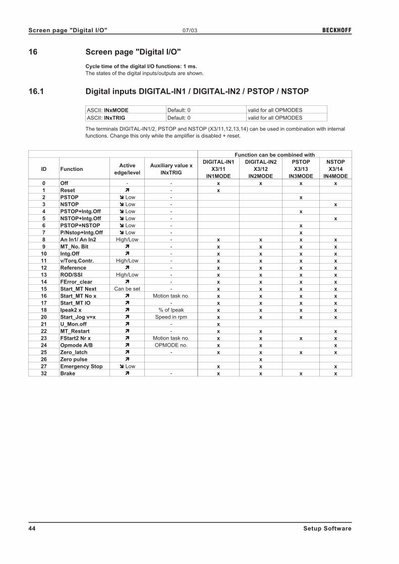
16 Screen page "Digital I/O"
Cycle time of the digital I/O functions: 1 ms.
The states of the digital inputs/outputs are shown.
16.1 Digital inputs DIGITAL-IN1 / DIGITAL-IN2 / PSTOP / NSTOP
ASCII: INxMODE Default: 0 valid for all OPMODES
ASCII: INxTRIG Default: 0 valid for all OPMODES
The terminals DIGITAL-IN1/2, PSTOP and NSTOP (X3/11,12,13,14) can be used in combination with internal
functions. Change this only while the amplifier is disabled + reset.
Function can be combined with
ID FunctionActive
edge/level
Auxiliary value x
INxTRIG
DIGITAL-IN1
X3/11
IN1MODE
DIGITAL-IN2
X3/12
IN2MODE
PSTOP
X3/13
IN3MODE
NSTOP
X3/14
IN4MODE
0 Off - - x x x x
1 Reset � - x
2 PSTOP � Low - x
3 NSTOP � Low - x
4 PSTOP+Intg.Off � Low - x
5 NSTOP+Intg.Off � Low - x
6 PSTOP+NSTOP � Low - x
7 P/Nstop+Intg.Off � Low - x
8 An In1/ An In2 High/Low - x x x x
9 MT_No. Bit � - x x x x
10 Intg.Off � - x x x x
11 v/Torq.Contr. High/Low - x x x x
12 Reference � - x x x x
13 ROD/SSI High/Low - x x x x
14 FError_clear � - x x x x
15 Start_MT Next Can be set - x x x x
16 Start_MT No x � Motion task no. x x x x
17 Start_MT IO � - x x x x
18 Ipeak2 x � % of Ipeak x x x x
20 Start_Jog v=x � Speed in rpm x x x x
21 U_Mon.off � - x
22 MT_Restart � - x x x
23 FStart2 Nr x � Motion task no. x x x x
24 Opmode A/B � OPMODE no. x x x
25 Zero_latch � - x x x x
26 Zero pulse � x
27 Emergency Stop � Low x x x
32 Brake � - x x x x
44 Setup Software
Screen page "Digital I/O" 07/03 BECKHOFF

16.1.1 Description of the digital inputs
0, Off No function.
1, Reset Software reset of the servo amplifier in the event of a fault. All the functions and displays are set to the initial
status. Parameters that are not stored in the EEPROM are erased, the parameter set that is stored in the
EEPROM is loaded.
If any of the error messages F01, F02, F03, F05, F08, F13, F16 or F19 are present, then no software-reset will
be carried out, just the error message will be deleted. This means that, for example, the encoder output signals
are stable and can continue to be evaluated by the controls.
2, PSTOP Limit-switch function. A LOW signal on the input terminal PSTOP (terminal X3/13) inhibits the positive direction
of rotation (clockwise, when looking at the motor shaft, at the A-end of the motor: parameter ROTARY
DIRECTION positive). The motor brakes (with emergency ramp), and stands with the I-component under
control, mechanical disconnection (stop) is not permitted.
A falling edge releases the brake, the 0V level disables the negative setpoint.
3, NSTOP Limit-switch function. A LOW signal on the input terminal NSTOP (terminal X3/14) inhibits the negative direction
of rotation (counterclockwise, when looking at the motor shaft at the A-end of the motor: parameter ROTARY
DIRECTION positive). The motor brakes (with emergency ramp), and stands with the I-component under
control, mechanical disconnection (stop) is not permitted.
A falling edge releases the brake, the 0V level disables the positive setpoint.
4, PSTOP+Intg.Off Limit-switch function. A LOW signal on the input terminal PSTOP (terminal X3/13) inhibits the positive direction
of rotation (clockwise, when looking at the motor shaft, at the A-end of the motor: parameter ROTARY
DIRECTION positive). The motor brakes (with emergency ramp), and stands without the I-component under
proportional control, mechanical disconnection (stop) is permitted.
A falling edge releases the brake, the 0V level disables the negative setpoint.
5, NSTOP+Intg.Off Limit-switch function. A LOW signal on the input terminal NSTOP (terminal X3/14) inhibits the negative direction
of rotation (counterclockwise, when looking at the motor shaft at the A-end of the motor: parameter ROTARY
DIRECTION positive). The motor brakes (with emergency ramp), and stands without the I-component under
proportional control, mechanical disconnection (stop) is permitted.
A falling edge releases the brake, the 0V level disables the positive setpoint.
6, PSTOP+NSTOP Limit-switch function STOP, regardless of the direction of rotation. A LOW-Signal on the input terminal PSTOP
(terminal X3/13) or NSTOP (terminal X3/14) inhibits both directions. The motor brakes (with emergency ramp),
and stands with the I-component under control, mechanical disconnection (stop) is not permitted.
A falling edge releases the brake, the 0V level switches the internal speed setpoint to 0V.
7, P/Nstop+Intg.Off Limit-switch function STOP, regardless of the direction of rotation. A LOW-Signal on the input terminal PSTOP
(terminal X3/13) or NSTOP (terminal X3/14) inhibits both directions. The motor brakes (with emergency ramp),
and stands without the I-component under proportional control, mechanical disconnection (stop) is permitted.
A falling edge releases the brake, the 0V level switches the internal speed setpoint to 0V.
8, An In 1/An In 2 Switches over the setpoint inputs An In ½. This function is only effective if the analog setpoint function
0,Xcmd=An In 1 has been selected.
High level at the input: Setpoint input 2 (terminals X3/6,7) is active
Low level at the input: Setpoint input 1 (terminals X3/4,5) is active
Setup Software 45
BECKHOFF 07/03 Screen page "Digital I/O"

9, MT_No_Bit Here you can select the motion tasks that are stored in the servo amplifier (numbers 1...7) or the homing (0).
The motion task number is presented externally at the digital inputs as a logical word, with a width of max. 3bits.
An input is required to start the motion task (17, Start_MT IO). If you wire up a reference switch (12, Reference)
and (also) want to start a following task (15, Start_MT Next) externally, the number of inputs that are available
for selecting the motion tasks will be further reduced.
Examples of possible assignments of the digital inputs for various applications:
Application
Motion task number: MSB ----------------> LSB selectable
motion task
numbersNSTOP PSTOP
DIGITAL-
IN 2
DIGITAL-
IN 1
7 motion tasks + homing,
without reference switch.Start_MT IO 2
22
12
00...7
3 motion tasks + homing,
without reference switch.
Start a following task that is
defined in the motion task, using
the setting "Start with I/O".
Start_MT Next Start_MT IO 21
20
0...3
3 motion tasks + homing,
with reference switch.2
12
0Reference Start_MT IO 0...3
1 motion task + homing,
with reference switch.
Start a following task that is
defined in the motion task, using
the setting "Start with I/O".
Reference Start_MT Next 20
Start_MT IO 0...1
10, Intg.Off Switch off the integral component of the speed controller, the P-gain remains at the set value, the actual-
(rotational) speed feedback remains in operation.
11, v/Torq.Contr. Bypasses the speed controller. The analog setpoint is taken 1:1 as the setpoint for current control, i.e. change
over from speed control to current (torque) control.
High-level at the input: torque control
Low-level at the input: speed control
12, Reference Polls the reference switch.
13, ROD/SSI Changeover of the encoder-emulation (position output) on connector X5.
High level at the input: SSI-compatible position signals
High level at the input: ROD-compatible position signals
14, FError_clear Clear the warning of a following error (display n03) or the response monitoring (display n04).
15, Start_MT Next The following task, that is defined in the motion task by "Start with I/O" is started. The target position of the
present motion task must be reached before the following task can be started.
16, Start_MT No x Start a motion task that is stored in the servo amplifier, by giving the motion task number. After the function has
been selected you can enter the motion task number as the auxiliary variable "x". Motion task number "0"
initiates homing/reference traverse. A rising edge starts the motion task, a falling edge cancels the motion task.
17, Start_MT IO Start of the motion task that has the number that is presented, bit-coded, at the digital inputs
(PSTOP/NSTOP/DIGITAL-IN1/DIGITAL-IN2, see function 9, MT_No_Bit ). A rising edge starts the motion task a
falling edge cancels the motion task.
18, Ipeak2 x Switch over to a second (lower) peak value of current. Scaled as x (0...100) % of the peak current of the
instrument. After the function has been selected you can enter the percentage value as the auxiliary variable
"x".
Make the conversion according to the following equation:
x =Ipeak2
* 100% => Ipeak2 =x
* IpeakIpeak 100%
46 Setup Software
Screen page "Digital I/O" 07/03 BECKHOFF

20, Start_Jog v=x Start of the setup mode "Jog Mode" with a defined speed. After selecting the function, you can enter the speed
in the auxiliary variable "x". The sign of the auxiliary variable defines the direction. A rising edge starts the
motion, a falling edge cancels the motion.
21, U_Mon.off Turns off the undervoltage monitoring function of the servo amplifier.
22, MT Restart Continues the motion task that was previously interrupted.
23, FStart2 Nr x Start of a motion task that is stored in the servo amplifier, with definition of the motion task number. After
selecting the function, you can enter the motion task number in the auxiliary variable "x". Motion task number
"0" starts the homing run. A rising edge starts the motion task.
Warning!The motion task does not stop automatically if the start signal is removed!
The motion task must be stopped by
— a falling edge on another digital input (configured with 16, Start_MT No x)
— the ASCII command STOP
— the STOP function of the setup software
24, Opmode A/B Changeover of the operating mode (OPMODE). The numbers of the OPMODES that are to be changed over
are entered in the auxiliary variable "x" as a decimal number. You have to calculate this decimal value from a
2-byte hex value.
Bits 0... 7 of the hex value contain the number of the OPMODE to which the system changes when a falling
edge is detected at the appropriate input; bits 8... 15 contain the number for the response to a rising edge.
When the controller is switched on, the OPMODE is set according to the input level.
Example:
Preparation for the changeover between OPMODE 1 (LOW state) and OPMODE 2 (HIGH state) according to
the state of the digital input DIGI-INI.
Function DIGI-IN1 = 24
2 Byte Hex value: "0801" => decimal value: "2049"
Auxiliary value "x" = 2049
25, Zero_latch Sets the ROD zero pulse offset. The current position, depending on the ROD resolution that is set, is calculated
at the rising edge and stored as NI-Offset. This function is used to perform an automatic save of all parameters.
26, Pos_latch An edge causes a freezing of the actual position. The 32-Bit value is stored in the variable LATCHX32 (positive
edge) or LATCHX32N (negative edge). The 16-Bit value (absolute within a revolution) is stored in the variable
LATCHX16 (positive edge) or LATCHX1N (negative edge). The Latch procedure taken place is communicated
about the corresponding status bits. The min. Pulse length wich can be read by this input (Low/High and
High/Low toggle) is 500 µsek. For CANopen the minimum distance between two Latch impulses is 8 msek.
Setup Software 47
BECKHOFF 07/03 Screen page "Digital I/O"

27, Emergency Stop The LOW level initiates an emergency-stop phase (motion is canceled and the drive is stopped, using the
EMERGENCY RAMP). Regardless of the OPMODE that is currently set, the speed controller is activated during
the emergency-stop phase.
32, Brake A rising edge at the input triggers the braking output of the servo amplifier.
This function is only available while the amplifier is disabled. If an error message is active, the brake cannot be
de-energized.
Warning!With suspended loads, this function will lead to slipping of the axis!
48 Setup Software
Screen page "Digital I/O" 07/03 BECKHOFF

16.2 Digital outputs DIGITAL-OUT1 / DIGITAL-OUT2
ASCII: OxMODE Default: 0 valid for all OPMODES
ASCII: OxTRIG Default: 0 valid for all OPMODES
You can combine the following standard pre-programmed functions with the digital outputs
DIGITAL-OUT1 (O1MODE, terminal X3/16) or DIGITAL-OUT2 (O2MODE, terminal X3/17). Change this only
while the amplifier is disabled + reset.
The following level information refers to the output at additional inverting interface terminals (e.g. Phoenix
DEK-REL-24/I/1), see Installation Manual.
High functions:
The presence of the function that is set is indicated by a High signal on the corresponding interface terminal.
Low functions:
The presence of the function that is set is indicated by a Low signal on the corresponding interface terminal.
ID Function Logic Auxiliary value OxTRIG
0 Off - -
1 v_act<x High speed (rpm)
2 v_act>x High speed (rpm)
3 Mains-RTO Low -
4 Regen off High -
5 Sw_limit High -
6 Pos.>x High position (increments)
7 InPos High -
8 I_act<x High current (mA)
9 I_act>x High current (mA)
10 FError Low -
11 I²t High -
12 Posreg.1 High -
13 Posreg.2 High -
14 Posreg.3 High -
15 Posreg.4 High -
16 Next-InPos High -
17 Error/Warn High -
18 Error High -
19 DC_Link>x High voltage (V)
20 DC_Link<x High voltage (V)
21 ENABLE High -
22 Zero_pulse High -
23 Reserved - -
24 Ref_OK High -
25-27 Reserved - -
28 Posreg. 0 High -
29 Posreg. 5 High -
Setup Software 49
BECKHOFF 07/03 Screen page "Digital I/O"

16.2.1 Description of the digital outputs
0, Off No function assigned.
1, v_act<x As long as the absolute value for the motor speed is lower than a preset value (auxiliary value "x"), a
HIGH-signal will be output. After the function has been selected you can enter the speed in rev./min. as the
auxiliary value "x".
2, v_act>x As long as the absolute value for the motor speed is higher than a preset value (auxiliary value "x"), a
HIGH-signal will be output. After the function has been selected, you can enter the speed in rev./min. as the
auxiliary value "x".
3, Mains-RTO This signals the operational readiness of the amplifiers power output stage. After switching on the mains supply,
a LOW-signal is output until the DC-link circuit is fully charged up. A HIGH-signal is output when the charging of
the DC-link circuit is finished. If the DC-link voltage falls below 100V, then 0V will be output. The "Undervoltage"
monitoring is inactive.
4, Regen off Signals if the preset regen power (screen page "Basic Setup") is exceeded.
5, Sw_limit This produces a HIGH-signal if a software limit-switch is reached (a preset function of the
corresponding position register, set to "SW limit-switch 1" or "SW limit-switch 2" – the function is defined in the
screen page "Position Data").
6, Pos.>x If the position (angular position of the motor shaft) exceeds a preset value (auxiliary value "x"),
a HIGH-signal will be output. After the function has been selected, you can enter the signaling position in
increment (a number or fraction of motor turns N) as the auxiliary value "x".
Make the calculation according to the following equation:
x = 1048576 * N * counts
Maximum possible entry value: x = 231
= 2147483648, this corresponds to N = 2048
7, InPos When the target position for a motion task has been reached (the InPosition window), this is
signaled by the output of a HIGH-signal. A cable break will not be detected.
The width of the InPosition window for all the valid motion tasks is entered in the Position Data screen page.
If a sequence of motion tasks is performed one after another, then the signal for reaching the final position of
the motion-task sequence will be output (target position of the last motion task).
Signaling that the target position of each motion task has been reached, in a sequence of motion tasks, can be
achieved with the function "16, Next_InPos".
8, I_act<x The output is a HIGH-signal, as long as the absolute r.m.s. value of the actual current is lower than a defined
value in mA (auxiliary value "x").
After the function has been selected, you can enter the current value as the auxiliary value "x".
9, I_act>x The output is a HIGH-signal, as long as the absolute r.m.s. value of the actual current is higher than a defined
value in mA (auxiliary value "x").
After the function has been selected, you can enter the current value as the auxiliary value "x".
50 Setup Software
Screen page "Digital I/O" 07/03 BECKHOFF

10, FError If the position goes outside the preset contouring-error window, this is indicated by a LOW-signal. The width of
the following error window is entered in the screen page "Position" for all the valid motion tasks.
11, I²t If the preset I²t monitoring threshold is reached (screen page "Current" ) this is indicated by a HIGH-signal.
12...15, Posreg.1...4 The preset function of the corresponding position register (the function is defined in the screen page "Position
Data") is indicated by a HIGH-signal.
16, Next-InPos The start of each motion task in an automatically executed sequence of motion tasks is signaled by an inversion
of the output signal. The output produces a Low signal at the start of the first motion task of the motion task
sequence.
17, Error/Warn The output produces a HIGH-signal if an error or a warning message is signaled by the servo amplifier.
18, Error The output produces a HIGH-signal if an error is signaled by the servo amplifier.
19, DC-Link>x A HIGH-signal is output if the actual value of the DC-link voltage is higher than a defined value in volts (auxiliary
value "x").
After the function has been selected, you can enter the voltage value as the auxiliary value "x".
20, DC-Link<x A HIGH-signal is output if the actual value of the DC-link voltage is lower than a defined value in volts (auxiliary
value "x").
After the function has been selected, you can enter the voltage value as the auxiliary value "x".
21, ENABLE A HIGH-signal is output if the servo amplifier is enabled.
To obtain the enable, the external Enable signal on terminal X3/15 must be present, the Enable status must be
set in the setup software (or via the fieldbus interface) and no errors must be present that would cause an
automatic internal disabling of the servo amplifier.
22, Zero pulse The zero mark/pulse (HIGH-signal) is indicated by the encoder-emulation. This function is only useful at very
low speeds.
24, Ref_OK The output signals High, if a reference point is available. Reference traverse (homing) has been carried out, or a
reference point has been set.
28, Posreg 0 The preset function of the corresponding position register is indicated by a HIGH-signal. Valid only with
expansion card -I/0-14/08-.
29, Posreg 5 The preset function of the corresponding position register is indicated by a HIGH-signal. Valid only with
expansion card -I/0-14/08-.
Setup Software 51
BECKHOFF 07/03 Screen page "Digital I/O"

17 Screen page "Current"
Use the default values for the motor. Please do not make any alterations to the settings for the current controller
unless they have been discussed with our applications department.
Cycle time of the current controller: 62.5 µs
Irms ASCII: ICONT Default: 50% rated current valid for all OPMODES
Sets the rated output current that is required. The adjustment is usually made to I0 , the standstill current for the
motor that is connected. The value that can be entered is limited to the rated current of the amplifier or the
standstill current of the motor Io (the lower of the two values). The function is used in the monitoring of the
actual r.m.s. current that is drawn. The limit that is set by the Irms-setting reacts after approx. TI2t = 5 sec at
maximum load. The calculations for current settings other than the rated values are made according to the
equation:
TI2T =I²rms * 15s
I²peak - I²rms
Ipeak ASCII: IPEAK Default: 50% peak current valid for all OPMODES
Sets the required pulse current (r.m.s. value). The value that can be entered is limited to the rated peak current
of the motor or amplifier (the lower of the two values).
Ref.-Ipeak ASCII : REFIP Default : 50% peak current Valid for all OPMODES
This sets the required pulse current (r.m.s. value) for Homing 7 (homing to the hardware stop, with zero-mark
detection) and for "Wake & Shake" commutation with external encoder systems. The entry is limited by the
lower value of the peak currents for the amplifier and motor.
I²t message ASCII: I2TLIM Default: 80 % valid for all OPMODES
Sets the level, as a percentage value of the r.m.s. current, above which a message will be sent to one of the
programmable outputs DIGITAL-OUT1/2 (X3/16 or X3/17). A warning appears in the display.
KP ASCII: MLGQ Default: 1 valid for all OPMODES
Determines the proportional gain of the current controller.
Normalization: at KP=1 and at a control deviation I_cmd -I_act = peak armature current
the rated motor voltage will be output.
Tn ASCII: KTN Default: 0,6 ms valid for all OPMODES
Determines the integral-action time (integration time constant) of the current controller.
52 Setup Software
Screen page "Current" 07/03 BECKHOFF

18 Screen page "Speed"
Use the default values for the motor as a starting point for optimization.
Cycle time of the speed controller: 250 µs
SpeedLimit ASCII: VLIM Default: 3000 rpm valid for OPMODES 0+1
Limits the motor speed. The maximum value also depends on the used motor and encoder.
Rotary Direction ASCII: DIR Default: 1 valid for all OPMODES
Fixes the direction of rotation of the motor shaft, referred to the polarity of the setpoint.
Make changes only while the amplifier is disabled + reset. This parameter is not available, if a SERCOS
interface is built-in.
After changing the rotary direction the hardware limit switches have to be exchanged.
Standard setting: right-hand (cw) rotation of the motor shaft (looking at the shaft end), with:
— positive voltage on terminal X3/4 (+ ) against terminal X3/5 ( - ) or
— positive voltage on terminal X3/6 (+ ) against terminal X3/7 ( - )
ID Function
0 negative
1 positive
Setp. Ramp+ ASCII: ACC Default: 10 ms valid for OPMODES 0+1
Limits the rate of increase of the internal setpoint processing during acceleration to the speed limit (valid for
both directions). A jump or step in the setpoint that is provided will be turned into a smoother, more favorable
transition. As long as the ramp time is less than the mechanically limited rise time of the system, the response
time of the system will not be negatively affected.
The ramp time settings are still effective if the limit-switches are activated.
Depending on the setting of the parameter ACCUNIT, acceleration time or ramp gradient will be set.
Setp. Ramp– ASCII: DEC Default: 10 ms valid for OPMODES 0+1
Limits the rate of decrease of the internal setpoint processing during braking to the zero speed (valid for both
directions). A jump or step in the setpoint that is provided will be turned into a smoother, more favorable
transition.
As long as the ramp time is less than the mechanically limited fall time of the system, the response time of the
system will not be negatively affected. In most cases the Setp.ramp+ and Setp.ramp– can be set to the same
value.
The ramp time settings are still effective if the limit-switches are activated.
Depending on the setting of the parameter ACCUNIT, acceleration time or ramp gradient will be set.
Setup Software 53
BECKHOFF 07/03 Screen page "Speed"

Overspeed ASCII: VOSPD Default: 3600 rpm valid for all OPMODES
Determines the upper limit for the motor speed. If this limit is exceeded, the servo amplifier switches into the
overspeed fault condition (error message F08).
Emergency ramp ASCII: DECSTOP Default: 10 ms valid for all OPMODES
The braking ramp for emergency braking. This braking ramp is used if the message n03, following error or n04,
response monitoring occurs, as well as on the activation of a hardware or software limit-switch.
Dis Ramp ASCII : DECDIS Default : 10 ms Valid for all OPMODES
If the output stage is disabled (by removal of the hardware or software enable), the internal speed setpoint
is run down to 0 along this ramp. When the speed has fallen below 5 rpm the output stage is disabled.
This ramp is only effective for motors that have a brake configured.
KP ASCII: GV Default: 1 valid for OPMODES 0+1
Determines the proportional gain (also known as AC-gain). Increase the value up to the level where the motor
starts to oscillate, and then back it off until the oscillations have clearly stopped. Typical values for this setting
are between 10 and 20.
Normalization: at KP = 1 and a control deviation of v_cmd -v_act = 3000 rev/min the instrument delivers the
peak current.
Tn ASCII: GVTN Default: 10 ms valid for OPMODES 0+1
Determines the integration time constant. Smaller motors permit shorter integration times; larger motors or high
moments of inertia in the load usually require integration times of 20 ms or more. With Tn = 0 ms the
I-component is switched off.
PID-T2 ASCII: GVT2 Default: 1 ms valid for all OPMODES
Affects the proportional gain (P-gain) at medium frequencies. It is often possible to improve the damping of the
speed control loop by increasing PID-T2 to about Tn/3. The setting is made, if required, after the basic setting of
KP and Tn.
Feedback ASCII: GVFBT Default: 0,4 ms valid for all OPMODES
If necessary, the time constant for the PT1-filter in the actual speed feedback (tachometer smoothing) can be
altered. This may improve the step response and smoothness of running, particularly for very small, highly
dynamic motors.
PI-PLUS ASCII: GVFR Default: 1 valid for OPMODES 0+1
This parameter only effects when the I-component is switched on (GVTN � 0).
With the default setting, the speed controller functions as a standard PI-controller with slight overshoot in the
step response. If PI-PLUS is reduced to 0.65, the overshoot is avoided and the actual value approaches the
setpoint slowly.
Optionally, you can reduce Tn. This makes the drive stiffer for the same step response.
54 Setup Software
Screen page "Speed" 07/03 BECKHOFF

19 Screen page "Position" (PI)
Cycle time of the position controller: 250 µs
Subscreens
Position Data Opens the screen page "Position Data"
Homing Opens the screen page "Homing"
Gearing Opens the screen page "Gearing"
Ff Factor ASCII: GPFFV Default: 1 valid for OPMODES 4,5,8
Determines the feed-forward factor for the position controller. Feed-forward is used to ease the task of the
position controller. A better setting for the Ff-factor means a better utilization of the dynamic range of the
position controller. The most favorable setting (usually about 1.0) depends on factors external to the drive, such
as friction, dynamic resistance, and stiffness.
KV ASCII: GP Default: 0,15 valid for OPMODES 4,5,8
Determines the proportional gain for the position controller.
Normalization: speed in m/s at 1 mm position deviation.
Tn ASCII: GPTN Default: 10 ms valid for OPMODES 4,5,8
Determines the integral-action time (integration time constant) for the position controller.
Tn = 0 ms switches off the I-component.
max.Following Error ASCII: PEMAX Default: 262144 valid for OPMODES 4,5,8
The following error is the maximum difference (+/- window) between the position setpoint and the actual position
that is permitted during processing. If the value leaves this window, then the position controller generates an
error message and brakes the drive, using the emergency ramp.
KP ASCII: GPV Default: 7 valid for OPMODES 4,5,8
Determines the proportional gain for the speed section of the controller. Increase the value up to the level where
the motor starts to oscillate, and then back it off until the oscillations have clearly stopped. Typical values are
the same as for the KP of the speed controller.
Normalization: as for the KP of the speed controller
PID-T2 Displays the value from the screen page "Speed"
Feedback Displays the value from the screen page "Speed"
Mode / Position Feedback
ASCII: EXTPOS Default: 0 valid for all OPMODES
Mode
Determines the type of position control loop (P/PI). With a P position control this screen page appears in a
different layout.
Position feedback
Determines the feedback source for the internal position controller. For most applications, the position infor-
mation for commutation and for position control are derived from the same source. This source is determined on
the "FEEDBACK" screen page, and can be either a resolver or an Endat/Hiperface encoder. In certain situa-
tions it may be advisable to derive the position information for commutation from a different source to that for
the position control. In such a case the feedback parameter will continue to be the source for commutation, and
the source for the position control will be given by gearing mode.
Standard feedback
- Feedback type is set by feedback
- It is not possible to read in an encoder via X1 or X5
Read external (ROD/SSI) for fieldbus
- Feedback type is set by feedback, external encoder is set by gearing mode
External (ROD/SSI) for position control
- Not possible in this mode
Setup Software 55
BECKHOFF 07/03 Screen page "Position" (PI)

20 Screen page "Position" (P)
Cycle time of the position controller: 250 µs
Subscreens
Position Data Opens the screen page "Position Data"
Homing Opens the screen page "Homing"
Gearing Opens the screen page "Gearing"
Ff Factor ASCII: GPFFV Default: 1 valid for OPMODES 4,5,8
Determines the feed-forward factor for the position controller. Feed-forward is used to ease the task of the
position controller. A better setting for the Ff-factor means a better utilization of the dynamic range of the
position controller. The most favorable setting (usually about 1.0) depends on factors external to the drive, such
as friction, dynamic resistance, and stiffness.
KV ASCII: GP Default: 0,15 valid for OPMODES 4,5,8
Determines the proportional gain for the position controller.
Normalization: speed in m/s at 1 mm position deviation.
max.Following Error ASCII: PEMAX Default: 262144 valid for OPMODES 4,5,8
The following error is the maximum difference (+/- window) between the position setpoint and the actual position
that is permitted during processing. If the value leaves this window, then the position controller generates an
error message and brakes the drive, using the emergency ramp.
Mode / Position Feedback
ASCII: EXTPOS Default: 0 valid for all OPMODES
Mode
Determines the type of position control loop (P/PI). With a PI position control, this screen page appears in a
different layout.
Position feedback
Determines the feedback source for the internal position controller. For most applications, the position infor-
mation for commutation and for position control are derived from the same source. This source is determined on
the "FEEDBACK" screen page, and can be either a resolver or an Endat/Hiperface encoder. In certain situa-
tions it may be advisable to derive the position information for commutation from a different source to that for
the position control. In such a case the feedback parameter will continue to be the source for commutation, and
the source for the position control will be given by gearing mode.
Standard feedback
- Feedback type is set by feedback
- it is not possible to read in an encoder via X1 or X5
Read external (ROD/SSI) for fieldbus
- Feedback type is set by feedback, external encoder is set by gearing mode
External (ROD/SSI) for position control
- Feedback type is set by external source via gearing mode
56 Setup Software
Screen page "Position" (P) 07/03 BECKHOFF

21 Screen page "Homing"
The reference traverse (homing) is an absolute task, that is used to zero the drive for subsequent positioning
operations. You can choose between various types of homing.
After homing, the drive reports "InPosition" and then enables the position controller in the servo amplifier.
Take care that the zero point of the machine (reference point) is in a position thatpermits the subsequent positioning operations. The software limit-switches that wereset as parameters may be ineffective. The axis could move on to the hardwarelimit-switch or even the mechanical stop. There is a risk of damage.If the reference point (zero point of the machine) is approached with excessivevelocity, for instance because of high moments of inertia, it may be overshot and, inthe worst case, move on to the hardware limit-switch or even the mechanical stop.There is a risk of damage.The position controller cannot be operated without first making a reference traverse(homing).A homing/reference traverse must be made after the 24V auxiliary voltage has beenswitched on.The start signal must not be removed during homing.The start signal must remain present until the "InPosition" message appears.
Start ASCII: MH Default: - valid for OPMODE 8
Radio button to start homing.
The SW-enable is set automatically when homing starts. Homing will only be startedin OPMODE 8. However, the SW-enable is set in all OPMODES. The drive cantherefore be accelerated by an analog setpoint that is applied, if the STARTcommand is executed in OPMODES1 or 3.
Stop ASCII: STOP Default: - valid for all OPMODES
Radio button to stop (cancel) the homing. The SW-enable remains set!
Setup Software 57
BECKHOFF 07/03 Screen page "Homing"

Reference traverse ASCII: NREF Default: 0 valid for OPMODE 8
You can choose which type of reference traverse should be performed. A preset zero-point offset (screen page
"Encoder" is taken into account for the position output and display.
Exception: Homing 5 — in this case the true current position is displayed.
You can shift the zero-crossing point of the motor shaft within one turn, at will, by using the "NI offset"
parameter (screen page "Encoder").
Zero-point recognition: the reference point is set to the first zero-crossing point of the feedback unit (zero mark)
after recognition of the reference switch transition. Two-pole resolvers and all encoders have just one
zero-crossing per turn, so the positioning at the zero mark is unambiguous within a motor turn. For 4-pole
resolvers there are two zero-crossings per turn, and for 6-pole resolvers there are three zero-crossings.
If the transition of the reference switch lies very close to the zero-crossing point of the feedback unit, then the
positioning to the zero mark can vary by one motor turn.
The repetition accuracy of homing operations that are made without zero-pointrecognition depends on the traversing speed and the mechanical design of thereference switch or limit-switch.
Homing 0 Sets the reference point to the setpoint position (the following error is lost).
Homing 1 Traverse to the reference switch with zero-mark recognition.
In this case, a reference traverse can also be made without hardware limit-switches. The precondition is one of
the initial situations shown below:
negative traverse,
positive rotation
negative traverse,
negative rotation
Homing 2Move to hardware limit-switch, with zero-mark recognition. The reference point is set to the first
zero-crossing of the feedback unit (NM, zero mark) beyond the limit-switch.
Homing 3Move to reference switch, without zero-mark recognition. The reference point is set to the
transition of the reference switch.
Homing 4Move to hardware limit-switch, without zero-mark recognition. The reference point is set to the
transition of the hardware limit-switch.
Homing 5Move to the next zero-mark of the feedback unit. The reference point is set to the next
zero-mark of the feedback unit.
Homing 6 Sets the reference point to the actual position (the following error is not lost).
Homing 7
Move to mechanical stop, with zero-mark recognition. The reference point is set to the first
zero-crossing of the feedback unit (NM, zero mark) beyond mechanical stop.
The pulse current is set by the parameter REF.-IPEAK on the screen page "Current controller".
Homing 8
Drives to an absolute SSI position. At the start of the homing run, a position is read in from the
SSI input (GEARMODE=7), converted according to the scaling factors GEARI and GEARO and
the reference offset, and then used a the target position.
On the following pages you can find the paths traversed during homing types 1 to 5 for every
possible initial situation (positive rotation, negative and positive directions of motion).
The meanings of the abbreviations in the drawings are:
N limit-switch NSTOP P limit-switch PSTOP SP start position
R reference switch vref preset velocity NM zero mark of the resolver
58 Setup Software
Screen page "Homing" 07/03 BECKHOFF

21.1 Homing 1
Homing with reference switch, negative direction of motion, positive rotation, with zero-mark
Warning!Before starting homing, check the safety of the system, since the load may move,even if the limit-switches are disconnected or defective.The limit-switch functions 2, PSTOP and 3, NSTOP must be activated to achieve the fullhoming functionality.
Homing with reference switch, positive direction of motion, positive rotation, with zero-mark
Warning!Before starting homing, check the safety of the system, since the load may move,even if the limit-switches are disconnected or defective.The limit-switch functions 2, PSTOP and 3, NSTOP must be activated to achieve the fullhoming functionality.
Setup Software 59
BECKHOFF 07/03 Screen page "Homing"

21.2 Homing 2
Homing without reference switch, negative direction of motion, positive rotation, with zero-mark
Warning!Hardware limit-switches must be present and connected.The limit-switch functions 2, PSTOP and 3, NSTOP must be switched on.
Homing without reference switch, positive direction of motion, positive rotation, with zero-mark
Warning!Hardware limit-switches must be present and connected.The limit-switch functions 2, PSTOP and 3, NSTOP must be switched on.
60 Setup Software
Screen page "Homing" 07/03 BECKHOFF

21.3 Homing 3
Homing with reference switch, negative direction of motion, positive rotation, without zero-mark
Warning!Before starting homing, check the safety of the system, since the load may move,even if the limit-switches are disconnected or defective.The limit-switch functions 2, PSTOP and 3, NSTOP must be activated to achieve the fullhoming functionality.
Homing with reference switch, positive direction of motion, positive rotation, without zero-mark
Warning!Before starting homing, check the safety of the system, since the load may move, evenif the limit-switches are disconnected or defective.The limit-switch functions 2, PSTOP and 3, NSTOP must be activated to achieve the fullhoming functionality.
Setup Software 61
BECKHOFF 07/03 Screen page "Homing"

21.4 Homing 4
Homing without reference switch, negative direction of motion, positive rotation, without zero-mark
Warning!Hardware limit-switches must be present and connected.The limit-switch functions 2, PSTOP and 3, NSTOP must be switched on.
Homing without reference switch, positive direction of motion, positive rotation, without zero-mark
Warning!Hardware limit-switches must be present and connected.The limit-switch functions 2, PSTOP and 3, NSTOP must be switched on.
62 Setup Software
Screen page "Homing" 07/03 BECKHOFF

21.5 Homing 5
Homing without reference switch, negative direction of motion, positive rotation, with zero-mark
Homing without reference switch, positive direction of motion, positive rotation, with zero-mark
Behavior for successively repeated starts of Homing 5:The position controller can only hold the motor in the zero position by passing thezero mark by ± 1 count. On a repeated start of Homing 5, depending on the position(1 count in advance of or 1 count behind the zero-mark) and the count direction, themovement may be a full motor turn!
Setup Software 63
BECKHOFF 07/03 Screen page "Homing"

21.6 Homing 7
Homing to mechanical stop, negative direction of motion, positive rotation, with zero-mark
Homing to mechanical stop, positive direction of motion, positive rotation, with zero-mark
Warning!Using this type of homing run can damage the mechanical stop on the machine. Thepeak current Ipeak and the continuous current Irms are limited for the duration ofthe homing run.A more severe limiting of the current is possible. (see parameter Ref.-Ipeak).
64 Setup Software
Screen page "Homing" 07/03 BECKHOFF

Direction of motion ASCII: DREF Default: 0 valid for OPMODE 8
Determines the direction of motion for homing. The setting "distance-dependent" is only relevant for Homing 5
(within one turn). In this case, the direction is chosen to give the shortest distance to the zero-mark. This
parameter also defines the direction of motion for a Modulo type of axis.
ID Function
0 negative direction
1 positive direction
2 zoned distance
v for homing ASCII: VREF Default: 0 valid for OPMODE 8
Determines the velocity for the homing operation. The sign is automatically fixed by the direction of motion that
is selected. The dimension is set by VUNIT .
Accel. ramp ASCII: ACCR Default: 10 ms valid for OPMODE 8
The acceleration ramp for the homing operation. The dimension is set by ACCUNIT. Entry e.g. in milliseconds
(1 ... 32767 ms). The ramp is also valid for constant velocity mode.
Decel. ramp ASCII: DECR Default: 10 ms valid for OPMODE 8
The deceleration (braking) ramp for homing. The dimension can be set by ACCUNIT. Entry e.g. in milliseconds
(1 ... 32767 ms). The ramp is also valid for constant velocity mode. This deceleration ramp is only used if the
operating mode allows it. For homing to a hardware limit-switch, the emergency ramp is used.
Offset ASCII: ROFFS Default: 0 valid for OPMODE 8
With the reference offset you can assign an absolute position value other than 0 to the reference point. With an
offset for the reference position you are not actually making a physical change, but the offset is used as a
reference value within the position control of the servo amplifier. Homing to the reference switch will then not
finish at zero, but at the preset reference offset value. The reference offset must be set before homing is
started. The dimension is set by PUNIT. An alteration of the offset only takes effect after a new homing
operation.
The parameter "Resolution" must be set correctly for your application.
21.7 Jog mode
Jog mode is defined as an endless motion at a constant velocity. This type of operation can be started without a
reference point being set. The hardware limit-switches are monitored. Software limit-switches are only
monitored if a reference point has been set. Acceleration and deceleration ramps are taken from the settings for
homing.
v ASCII: VJOG Default: 0 valid for OPMODE 8
Determines the velocity for jog mode. The sign that is entered determines the direction of movement. Before
starting the jog mode, the velocity value must be taken on. The dimension is set by VUNIT .
F4 ASCII: MJOG Default: - valid for OPMODE 8
Start the jog mode by pressing the function key F4. The drive moves with the preset velocity in the direction,
which is indicated by the sign of the velocity for the jog mode "v", as long as the function key is pressed. If a
communication error occurs while pressing the button, the drive stops with the emergency deceleration ramp.
When the function "Jog mode" is started, the SW-enable is set automatically. TheFunction "Jog mode" is only started in OPMODE 8. However, the SW-enable is setin all OPMODES. The drive can therefore be accelerated by an analog setpoint thatis applied, if the START command is executed in OPMODES1 or 3.
Setup Software 65
BECKHOFF 07/03 Screen page "Homing"

22 Screen page "Position Data"
For each one of the positioning tasks you must define motion tasks. These motion tasks can be selected by a
motion task number, and are stored in the servo amplifier.
Motion task Stored in Precondition for storing Comments
1...180 EEPROM output stage disabled permanently stored
192...255 RAM none volatile storage
When the servo amplifier is switched on, the RAM motion blocks 192...255 are automatically pre-loaded with the
parameters of the EEPROM motion blocks 1...64.
Number Entry of a motion task number, to start the motion task from the PC.
Motion task table A new window appears, in which all motion tasks are represented in tabular form.
All motion task parameters can be entered in the table directly. The following operations are available:
� Cut
� Copy
� Paste
� Delete
The clipboard operations cut, copy and paste are only possible for complete rows, i.e. for these operations the
appropriate row must be selected. The deletion is possible both, row- and cellwise. A line can be selected either
by clicking on the row number, or through the keyboard shortcuts <Shitft>+<Space> (similar to Microsoft Excel).
All Edit operations are available through the Windows standard keyboard shortcuts.
Input via the screen page"Motion task parameters":
Double-clicking a line number in the table opens the screen page for the associated motion task. The use of the
dialogue "Motion task parameters" in relation to older versions of the software changed concerning the buttons
"OK", and "Cancel".Compared to older versions of the software, the functions of the buttons "OK" and "APPLY"
have changed. By clicking these buttons, the changes are no longer saved to the flash EEPROM but the values
in the associated table are changed instead. Writing the changes to the EEPROM is possible with the buttons
"OK" or "APPLY" on the screen page "Motion task table"
Start ASCII: MOVE Default: - valid for OPMODE 8
Start the motion task that has the number that can be seen in the NUMBER field. The amplifier must be enabled
(input X3/15 has a High signal).
The SW-enable is automatically set when the motion task starts. The motion task isonly started in OPMODE8. However, the SW-enable is set in all OPMODES. Thedrive can therefore be accelerated by an analog setpoint that is applied, if the STARTcommand is executed in OPMODES 1 or 3.The motion task is not started if the target position is beyond the defined SW-limitswitches (warning messages n06/n07 and n08)
Stop ASCII: STOP Default: - valid for OPMODE 8
Stops the current motion task. The SW-enable remains set!
66 Setup Software
Screen page "Position Data" 07/03 BECKHOFF

Axis type ASCII: POSCNFG Default: 0 valid for OPMODE 8
Here you select whether the axis is to be operated as a linear or a rotary axis.
ID Function Comments
0 linear
A linear axis is an axis with a limited range of travel. A linear axis moves within the
traversing limits that are given by the software limit-switches, both absolutely and
relatively. A reference point must be set.
The maximum range of movement is limited to +/- 2047 turns of the motor. If a
larger number (+/- 32767) is needed, please consult our applications department.
1 rotary
A rotary axis is an axis with unlimited travel. The software limit-switches have no
significance in this case. A rotary axis always makes a relative movement, even
if the tasks are entered as absolute ones. The actual position is set to zero with
every start. A reference point is not required.
2 modulo
The position of the position controller is limited to the range given by
(Modulo-Start-Pos … Modulo-End-Pos.). As soon as the end of this range
(Modulo-End-Pos.-1) is reached, the position begins again at (Modulo-Start-Pos).
So the absolute target positions for the motion tasks must lie within the valid range.
Any attempt to start an absolute motion task with a target position outside this range
will generate the warning n08 (motion task error). With relative motion tasks, the
target position will be corrected so that it always lies within the valid range. Since a
target position can be approached from two directions when positioning within the
modulo range, the "direction" parameter on the "Homing" screen page can be used
to define the preferred direction.
The same restrictions apply for the reference point as for axis type=linear, i.e. the
completion of a homing movement is a precondition for all positioning actions.
The limitation to the modulo range does not apply during the homing movement, in
other words, during the homing movement the position for the position controller is
treated the same as for axis type=linear.
The limitation to the modulo range is only activated after the homing movement has
been completed.
v_max ASCII: PVMAX Default: 100 valid for OPMODE 8
This parameter is used to adjust the maximum speed of movement to suit the limits of the operative machinery.
The calculation of the upper setting limit depends on the final limit speed of the drive. The value that is entered
is used as a limit for the "v_setp" entry in the motion tasks. During commissioning, you can limit the speed by
using v_max (without changing the setting for the motion blocks). A lower value of v_max overrides the v_setp
of the motion tasks.
t_acc/dec_min / a max ASCII: PTMIN Default: 1 ms valid for OPMODE 8
A drive is always so dimensioned that it can provide more power than the application requires. This parameter
determines the limit for the maximum mechanical acceleration time to v_max, that must not be exceeded by the
drive. This time is simultaneously valid as the minimum limit for the entry "t_accel_tot" (acceleration time from 0
to v_setp) and "t_brake_tot" (braking time from v_setp down to 0) for the motion tasks.
Depending on the setting of acceleration unit you can enter either the acceleration time or the acceleration in
the dimensional unit that has been selected.
InPosition ASCII: PEINPOS Default: 4000 valid for OPMODES 4,5,8
Sets the InPosition window. Determines at which distance from the set position the "InPosition" message should
be reported. The drive moves precisely to the target position.
Modulo-Start-Pos. ASCII : SRND Default : -231
valid for OPMODES 4,5,8
This parameter is used to define the start of the range of movement for a modulo axis.
The end of the range is defined by the parameter Modulo-End-Pos.
Modulo-End-Pos. ASCII : ERND Default : 231
-1 valid for OPMODES 4,5,8
This parameter is used to define the end of the range of movement for a modulo axis.
The start of the range is defined by the parameter Modulo-Start-Pos.
Setup Software 67
BECKHOFF 07/03 Screen page "Position Data"

Position register A programmable register that can have various functions assigned to it.
Make changes only while the amplifier is disabled + reset.
Position register
Function Comment 1 (SWE1) 2 (SWE2) 3 (SWE3) 4 (SWE4)
inactive - x x x x
Pos. not reached threshold for signal x x x x
Pos. overshot threshold for signal x x x x
SW limit-switch 1 limit-switch function x - - -
SW limit-switch 2 limit-switch function - x - -
SW limit-switches 1 / 2
The software limit-switches from part of the monitoring functions of the position controller.
SW limit-switch 1
The monitoring checks whether the actual position value is lower than the preset
value (the negative direction of travel is now inhibited – You have to leave
limit-switch 1 by moving in the positive direction. ).
SW limit-switch 2
The monitoring checks whether the actual position value is higher than the preset
value (the positive direction of travel is now inhibited – You have to leave
limit-switch 1 by moving in the negative direction.)
The drive brakes with the emergency ramp, and remains at standstill under torque.
The principle of positioning the software limit-switch can be seen in the diagram below:
Legend
MA1 : Machine stop, left
HE1 : Hardware limit-switch, left
NI : Zero pulse initiator (reference)
SE1 : Software limit-switch 1
SE2 : Software limit-switch 2
HE2 : Hardware limit-switch right
MA2 : Machine stop right
+ : Positive count direction
- : Negative count direction
ASCII: SWCNFG (set) Default: 0 valid for all OPMODES
ASCII: SWEx (position) Default: 0 valid for all OPMODES
Configuration variables for the position register. SWCNFG is a binary-coded bit-variable, and is transferred to
the ASCII terminal program as a decimal number.
Bit-variable SWCNFG
Bit Value Description Bit Value Description
20 0 Monitoring of SWE1 inactive
28 0 Monitoring of SWE3 inactive
1 Monitoring of SWE1 active 1 Monitoring of SWE3 active
21 0 Signal for actual position>SWE1
29 0 Signal for actual position>SWE3
1 Signal for actual position<SWE1 1 Signal for actual position<SWE3
22 0 SWE1 functions as signal threshold
210 0
Reserve1 SWE1 functions as SW limit-switch 1
23 0
Reserve 211 0
Reserve1 1
24 0 Monitoring of SWE2 inactive
212 0 Monitoring of SWE4 inactive
1 Monitoring of SWE2 active 1 Monitoring of SWE4 active
25 0 Signal for actual position>SWE2
213 0 Signal for actual position>SWE4
1 Signal for actual position<SWE2 1 Signal for actual position<SWE4
26 0 SWE2 functions as signal threshold
214 0
Reserve1 SWE2 functions as SW limit-switch 1
27 0
Reserve 215 0
Reserve1 1
68 Setup Software
Screen page "Position Data" 07/03 BECKHOFF
Resolution ASCII: PGEARI (numerator) Default: 10000 valid for OPMODE 8
ASCII: PGEARO (denominator) Default: 1 valid for OPMODE 8
The entry for the resolution of the motion tasks is in µm/Revolution. The resolution can be defined at will,
through the entries for the numerator/denominator.
Make changes only while the amplifier is disabled + reset.
Examples:
An entry of 10000/1 produces a resolution of 10 mm/turn
An entry of 10000/3 produces a resolution of 3.333 mm/turn
Rotary table with geared motor, i = 31 (31 motor turns for one turn of the table)
– The entry 360/31 provides operation with position entries in degrees, without rounding off.
The maximum range of movement is limited to +/- 2047 motor turns. If a larger range (+/- 32767) is required,
please consult our applications department.
GMT Opens the graphical motion tasking.
Graphical motion tasking is an advanced feature that lets you easily edit motion tasks with its graphical
interface. You can command multiple motions, process I/O, make decisions, add time delays and modify drive
process variables. The environment is easy to use, allowing you to program in an intuitive flow-chart.
Motion tasking has been supported by the amplifier since the product was introduced in 1998. In its original
form, motion tasking supported only chained moves in sequences executed either once or in infinite loops.
Graphical motion tasking extends the capabilities of moiton tasking by adding looping, comparing (<, =, >, etc.),
calling functions and setting process variables.
Setup Software 69
BECKHOFF 07/03 Screen page "Position Data"

23 Screen page "Motion task parameters"
You can use the ASCII-terminal to completely define motion blocks, with the "ORDER" command. You can
obtain further information about this command from our applications department.
Number Displays the currently active motion task number.
Type Selection of the basic motion task type.
Type Description
Motion Standard motion task
Delay Delay in ms
Comparison tests branch conditional on parameter value
Modify parameter set parameter value
Initialize loop define loop parameters
Decrement counter decrease loop counter by one step
Loop branch conditional on loop counter value
Jog move at constant velocity
Go to home / index /
registration + offsetmove to reference point
Depending upon selected type the representation of the screen page changes. The individual variants are
described in the following sections.
The motion task type “Motion” is always available, all other types presuppose an installed extension card
(DeviceNet, Sercos or I/O-14/08) and orient by the Graphical Motion Tasking and the DeviceNet communication
profile. You find further information in the appropriate manuals
70 Setup Software
Screen page "Motion task parameters" 07/03 BECKHOFF
23.1 Type Motion
Trajectory If the drop down list Trajectory is set to internal, the motion tasks from the internal trajectory generator are used.
Otherwise entries from the lookup table of the amplifier (can be downloaded over the CAN Download program)
are selected. You can get more information on this topic from our application department.
Velocity profile No. Selection of a velocity profile from the table selected by trajectory. You can get more information on this topic
from our application department.
Units (general) Select the unit for path and speed entries
Selection Path Velocity
Countsx = 1048576 * N * Incr.
with N = no. of motor turns, Nmax=+/- 2047
x = 140/32 * n * min * Incr.
with n = rotational speed of the motor shaft
SI / User µm µm/s
Type This selection determines whether the motion task is interpreted as a relative or an absolute task.
ABS movement to an absolute target position, referred to the reference point.
REL cmdrelative to last target (setpoint) position (in connection with motion block changeover: e.g.
summing operation)
REL actrelative to actual position at start (in connection with motion block changeover: e.g. register
control)
REL InPoswhen the load is in the InPosition window: relative to last target position when the load is
not in the InPosition window: relative to actual position at start
REL Latch pos. please contact our applications department.
REL Latch neg. please contact our applications department.
In the setup software, the transmission of an absolute task to the RAM of the servo amplifier is prevented for
axes of the ROTARY type.
s_cmd This parameter determines the distance to be traveled.
v_cmd-source The velocity can be defined in the motion block, or provided as an analog setpoint.
digital digital setpoint provision through v_cmd
analog An In 1analog setpoint provision at input An In 1 (terminals X3/4-5, scaling is used. The value is
read in at the start of the motion task.
v_cmd This parameter determines the velocity of movement for digital setpoint provision. If v_max is set to a value that
is less than v_cmd at a later time, the position controller will use the smaller value.
Setup Software 71
BECKHOFF 07/03 Screen page "Motion task parameters"
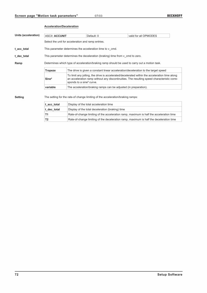
Acceleration/Deceleration
Units (acceleration) ASCII: ACCUNIT Default: 0 valid for all OPMODES
Select the unit for acceleration and ramp entries.
t_acc_total This parameter determines the acceleration time to v_cmd.
t_dec_total This parameter determines the deceleration (braking) time from v_cmd to zero.
Ramp Determines which type of acceleration/braking ramp should be used to carry out a motion task.
Trapeze The drive is given a constant linear acceleration/deceleration to the target speed
Sine²
To limit any jolting, the drive is accelerated/decelerated within the acceleration time along
an acceleration ramp without any discontinuities. The resulting speed characteristic corre-
sponds to a sine² curve.
variable The acceleration/braking ramps can be adjusted (in preparation).
Setting The setting for the rate-of change limiting of the acceleration/braking ramps:
t_acc_total Display of the total acceleration time
t_dec_total Display of the total deceleration (braking) time
T1 Rate-of-change limiting of the acceleration ramp, maximum is half the acceleration time
T2 Rate-of-change limiting of the deceleration ramp, maximum is half the deceleration time
72 Setup Software
Screen page "Motion task parameters" 07/03 BECKHOFF

Next Motion Task
Next motion task Select whether a new motion task should be started automatically, after the present task is finished.
The InPosition signal is only enabled when the last motion task (no further task) has been processed. You can
use the function "16, Next-InPos" to generate a signal at one of the digital outputs when each target position
within a sequence of motion tasks has been reached.
Next number The number of the next task, which will be started automatically after the present task is finished.
Accel./decel. Select the action to be taken when the target position for the present motion task is reached.
on v_act=0 The drive brakes to a stop in the target position. The next motion task is then started.
from targetThe drive moves at v_cmd of the present motion task to the target position, and then
accelerates through to v_cmd of the next task
to target
The changeover to the next task is brought so far forwards, that the v_cmd of the next
task is already achieved by the time the target of the present motion task has been
reached.
Start condition immediately The next task is started as soon as the target position is reached.
I/O
The next task is started by a signal at a digital input (one of the terminals X3/11...14).
This is only meaningful with "Accel./Decel to v=0".
Condition: the digital input must have the function "15, Start_MT Next" assigned, and the
target position must have been reached.
You can preselect the logic with the "Start with" parameter
Time
The next task is started with a defined delay after the target position has been reached.
You can enter the delay time with the "Delay time" parameter.
This is only meaningful with "Accel./Decel to v=0".
I/O or Time
The next task is started by a signal at a digital input (one of the terminals X3/11...14) or
after a defined delay.
This is only meaningful with "Accel./Decel to v=0".
The trigger is the event that occurs first (the start signal or the end of the delay time)
Condition: the digital input must have the function "15, Start_MT Next" assigned, and the
target position must have been reached.
You can preselect the logic with the "Start with" parameter, and enter the delay time with
the "Delay time" parameter.
Start by I/O edge The logic for the digital input that has the function "15, Start_MT Next" assigned to it.
LOW-level: 0 ... 7 V
HIGH-level: 12 ...3 0 V / 7 mA
Delay time The entry (in ms) for the delay time between reaching the target position and starting the next task.
23.2 Type Delay
Next number The number of the next task, which will be started automatically after the present task is finished.
Delay time The entry (in ms) for the delay time between reaching the target position and starting the next task.
Setup Software 73
BECKHOFF 07/03 Screen page "Motion task parameters"
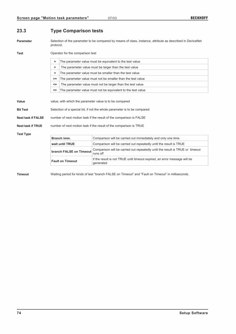
23.3 Type Comparison tests
Parameter Selection of the parameter to be compared by means of class, instance, attribute as described in DeviceNet
protocol.
Test Operator for the comparison test
= The parameter value must be equivalent to the test value
> The parameter value must be larger than the test value
< The parameter value must be smaller than the test value
>= The parameter value must not be smaller than the test value
<= The parameter value must not be larger than the test value
<> The parameter value must not be equivalent to the test value
Value value, with which the parameter value is to be compared
Bit Test Selection of a special bit, if not the whole parameter is to be compared.
Nest task if FALSE number of next motion task if the result of the comparison is FALSE
Nest task if TRUE number of next motion task if the result of the comparison is TRUE
Test Type
Branch imm. Comparison will be carried out immediately and only one time.
wait until TRUE Comparison will be carried out repeatedly until the result is TRUE
branch FALSE on TimeoutComparison will be carried out repeatedly until the result is TRUE or timeout
runs off
Fault on Timeoutif the result is not TRUE until timeout expired, an error message will be
generated
Timeout Waiting period for kinds of test “branch FALSE on Timeout” and “Fault on Timeout” in milliseconds.
74 Setup Software
Screen page "Motion task parameters" 07/03 BECKHOFF

23.4 Type Modify parameter
Parameter Selection of the parameter to be compared by means of class, instance, attribute as described in DeviceNet
protocol.
Value Value, which is to be assigned to the parameter
Next Motion Task
Next motion task Select whether a new motion task should be started automatically, after the present task is finished.
The InPosition signal is only enabled when the last motion task (no further task) has been processed. You can
use the function "16, Next-InPos" to generate a signal at one of the digital outputs when each target position
within a sequence of motion tasks has been reached.
Next number The number of the next task, which will be started automatically after the present task is finished.
Accel./decel. Select the action to be taken when the target position for the present motion task is reached.
on v_act=0 The drive brakes to a stop in the target position. The next motion task is then started.
from targetThe drive moves at v_cmd of the present motion task to the target position, and then
accelerates through to v_cmd of the next task
to target
The changeover to the next task is brought so far forwards, that the v_cmd of the next
task is already achieved by the time the target of the present motion task has been
reached.
Start condition immediately The next task is started as soon as the target position is reached.
I/O
The next task is started by a signal at a digital input (one of the terminals X3/11...14).
This is only meaningful with "Accel./Decel to v=0".
Condition: the digital input must have the function "15, Start_MT Next" assigned, and the
target position must have been reached.
You can preselect the logic with the "Start with" parameter
Time
The next task is started with a defined delay after the target position has been reached.
You can enter the delay time with the "Delay time" parameter.
This is only meaningful with "Accel./Decel to v=0".
I/O or Time
The next task is started by a signal at a digital input (one of the terminals X3/11...14) or
after a defined delay.
This is only meaningful with "Accel./Decel to v=0".
The trigger is the event that occurs first (the start signal or the end of the delay time)
Condition: the digital input must have the function "15, Start_MT Next" assigned, and the
target position must have been reached.
You can preselect the logic with the "Start with" parameter, and enter the delay time with
the "Delay time" parameter.
Start by I/O edge The logic for the digital input that has the function "15, Start_MT Next" assigned to it.
LOW-level: 0 ... 7 V
HIGH-level: 12 ...30 V / 7 mA
Delay time The entry (in ms) for the delay time between reaching the target position and starting the next task.
Setup Software 75
BECKHOFF 07/03 Screen page "Motion task parameters"

23.5 Type Initialize loop
initial value Number of counting steps of the loop
Next task Number of the motion task, which is to be processed after setting the counter
23.6 Type Decrement counter
Next Motion Task
Next motion task Select whether a new motion task should be started automatically, after the present task is finished.
The InPosition signal is only enabled when the last motion task (no further task) has been processed. You can
use the function "16, Next-InPos" to generate a signal at one of the digital outputs when each target position
within a sequence of motion tasks has been reached.
Next number The number of the next task, which will be started automatically after the present task is finished.
Accel./decel. Select the action to be taken when the target position for the present motion task is reached.
on v_act=0 The drive brakes to a stop in the target position. The next motion task is then started.
from targetThe drive moves at v_cmd of the present motion task to the target position, and then
accelerates through to v_cmd of the next task
to target
The changeover to the next task is brought so far forwards, that the v_cmd of the next
task is already achieved by the time the target of the present motion task has been
reached.
Start condition immediately The next task is started as soon as the target position is reached.
I/O
The next task is started by a signal at a digital input (one of the terminals X3/11...14).
This is only meaningful with "Accel./Decel to v=0".
Condition: the digital input must have the function "15, Start_MT Next" assigned, and the
target position must have been reached.
You can preselect the logic with the "Start with" parameter
Time
The next task is started with a defined delay after the target position has been reached.
You can enter the delay time with the "Delay time" parameter.
This is only meaningful with "Accel./Decel to v=0".
I/O or Time
The next task is started by a signal at a digital input (one of the terminals X3/11...14) or
after a defined delay.
This is only meaningful with "Accel./Decel to v=0".
The trigger is the event that occurs first (the start signal or the end of the delay time)
Condition: the digital input must have the function "15, Start_MT Next" assigned, and the
target position must have been reached.
You can preselect the logic with the "Start with" parameter, and enter the delay time with
the "Delay time" parameter.
Start by I/O edge The logic for the digital input that has the function "15, Start_MT Next" assigned to it.
LOW-level: 0 ... 7 V
HIGH-level: 12 ...30 V / 7 mA
Delay time The entry (in ms) for the delay time between reaching the target position and starting the next task.
76 Setup Software
Screen page "Motion task parameters" 07/03 BECKHOFF

23.7 Type Loop
if counter <> 0 Number of the motion task, which is to be processed if the counter is larger or smaller than zero
If counter = 0 Number of the motion task, which is to be processed if the counter equals zero
23.8 Type Jog
Velocity velocity in counts/sec for constant velocity mode
23.9 Type go to Home / Index / Registration + Offset
Reference
Home reference point set by the user
Indexreference points defined via DeviceNet
Registration
Offset Offset from the reference point
Units units for offset
Counts Offset in counts
SI Offset in SI units, unit is given by PUNIT
v_cmd source Source for the speed setpoint
digital v_cmd as speed setpoint
analog (SW1) speed setpoint from analog input 1
v_cmd speed setpoint in counts / 250 µsec for v_cmd source = digital
Acceleration/Deceleration
Units (acceleration) ASCII: ACCUNIT Default: 0 valid for all OPMODES
Select the unit for acceleration and ramp entries.
t_acc_total This parameter determines the acceleration time to v_cmd.
t_dec_total This parameter determines the deceleration (braking) time from v_cmd to zero.
Ramp Determines which type of acceleration/braking ramp should be used to carry out a motion task.
Trapeze The drive is given a constant linear acceleration/deceleration to the target speed
Sine²
To limit any jolting, the drive is accelerated/decelerated within the acceleration time along
an acceleration ramp without any discontinuities. The resulting speed characteristic corre-
sponds to a sine² curve.
variable The acceleration/braking ramps can be adjusted (in preparation).
Setting The setting for the rate-of change limiting of the acceleration/braking ramps:
t_acc_total Display of the total acceleration time
t_dec_total Display of the total deceleration (braking) time
T1 Rate-of-change limiting of the acceleration ramp, maximum is half the acceleration time
T2 Rate-of-change limiting of the deceleration ramp, maximum is half the deceleration time
Setup Software 77
BECKHOFF 07/03 Screen page "Motion task parameters"

Next Motion Task
Next motion task Select whether a new motion task should be started automatically, after the present task is finished.
The InPosition signal is only enabled when the last motion task (no further task) has been processed. You can
use the function "16, Next-InPos" to generate a signal at one of the digital outputs when each target position
within a sequence of motion tasks has been reached.
Next number The number of the next task, which will be started automatically after the present task is finished.
Accel./decel. Select the action to be taken when the target position for the present motion task is reached.
on v_act=0 The drive brakes to a stop in the target position. The next motion task is then started.
from targetThe drive moves at v_cmd of the present motion task to the target position, and then
accelerates through to v_cmd of the next task
to target
The changeover to the next task is brought so far forwards, that the v_cmd of the next
task is already achieved by the time the target of the present motion task has been
reached.
Start condition immediately The next task is started as soon as the target position is reached.
I/O
The next task is started by a signal at a digital input (one of the terminals X3/11...14).
This is only meaningful with "Accel./Decel to v=0".
Condition: the digital input must have the function "15, Start_MT Next" assigned, and the
target position must have been reached.
You can preselect the logic with the "Start with" parameter
Time
The next task is started with a defined delay after the target position has been reached.
You can enter the delay time with the "Delay time" parameter.
This is only meaningful with "Accel./Decel to v=0".
I/O or Time
The next task is started by a signal at a digital input (one of the terminals X3/11...14) or
after a defined delay.
This is only meaningful with "Accel./Decel to v=0".
The trigger is the event that occurs first (the start signal or the end of the delay time)
Condition: the digital input must have the function "15, Start_MT Next" assigned, and the
target position must have been reached.
You can preselect the logic with the "Start with" parameter, and enter the delay time with
the "Delay time" parameter.
Start by I/O edge The logic for the digital input that has the function "15, Start_MT Next" assigned to it.
LOW-level: 0 ... 7 V
HIGH-level: 12 ...3 0 V / 7 mA
Delay time The entry (in ms) for the delay time between reaching the target position and starting the next task.
78 Setup Software
Screen page "Motion task parameters" 07/03 BECKHOFF

24 Screen page "Gearing"
The servo amplifier receives a position setpoint from another instrument (master servo amplifier, stepper motor
control, encoder or similar) and controls the position of the motor shaft in synchronism with this master (control)
signal.
Cycle time of the electrical gearing: 250 µs. A value averaged over 1000 µs is used.
Gearing mode ASCII: GEARMODE Default: 6 valid for OPMODE 4
The servo amplifier can be controlled through different interfaces and from various sources.
For the connector pin assignments, see the Installation Manual.
ID Function Comments
0Encoder follower
Dig.I/O 24V (X3)
With an incremental encoder (track A/B, 24V signal level) connected to the
digital inputs DIGITAL-IN ½, terminals X3/11,12. An additional function
assignment for the inputs is not necessary, and any assignments on the
screen page "Digital I/O" will be ignored.
1Pulse / direction
Dig.I/O 24V (X3)
With a stepper motor control (pulse/direction, 24V signal level) connected to
the digital inputs DIGITAL-IN ½, terminals X3/11,12). An additional function
assignment for the inputs is not necessary, and any assignments on the
screen page "Digital I/O" will be ignored.
2 reserved
3Encoder follower
5V (X5)
Set encoder emulation to "INPUT". With an incremental encoder (track A/B,
5V signal level) connected to connector X5. In this case, the incremental
position signal from another amplifier can be used as the master signal.
4Pulse / direction,
5V (X5)
Set encoder emulation to "INPUT". With a stepper motor control
(pulse/direction, 5V signal level) connected to connector X5.
5 reserved reserved
6 Sin Encoder, (X1) With a sine/cosine encoder connected to connector X1.
7Sin Encoder, (X1)
+Protocol +analog
Read in the SSI position via the Encoder interface. Every 250µsec the SSI
position is captured and the difference to the preceding position is calculated.
Subsequently, this difference is multiplied by the scaling factor and added to
the last position setpoint.
Ratio ASCII: ENCIN (x) Default: 4096 valid for OPMODE 4
ASCII: GEARO (y) Default: 8192 valid for OPMODE 4
ASCII: GEARI (z) Default: 8192 valid for OPMODE 4
You can use the entry fields in this equation to determine the transmission ratio:
Ratio =Input pulses per turn
*y
(electr. gearing, correction factor through An In 2).x z
where: x = normalization for the input pulses (256 ... actual no. of pulses)
y/z = ratio with y = –32767 ... +32767 and z = 1 ... 32767
If you have any queries, please contact our applications department.
Setup Software 79
BECKHOFF 07/03 Screen page "Gearing"

25 Screen page "Drive status"
Run time ASCII: TRUN Default: - valid for all OPMODES
Display of the operational time of the servo amplifier, saved at 8 minute intervals. If the 24V-supply is switched
off, maximum 8 minutes of operation are unregistered.
Last 10 faults ASCII: FLTHIST Default: - valid for all OPMODES
The last 10 faults that occurred are displayed, together with the time of their occurrence, referred to the
operating hours.
Rate of occurrence ASCII: FLTCNT Default: - valid for all OPMODES
Display of the frequency of all faults that caused the servo amplifier to switch off.
Actual errors ASCII: ERRCODE Default: - valid for all OPMODES
Display of the errors presently being reported by the servo amplifier (corresponds to the error messages Fxx in
the LED-display on the front panel of the amplifier)
Actual warnings ASCII: STATCODE Default: - valid for all OPMODES
Display of the warnings presently being reported by the servo amplifier (corresponds to the
warnings nxx in the LED-display on the front panel of the amplifier)
Reset ASCII: CLRFAULT Default: - valid for all OPMODES
Software-reset of the servo amplifier. The servo amplifier must be disabled.
Present errors are deleted, the firmware is re-initialized, and communication is re-established.
If only errors marked with an asterisk in the error listing are present, then the errors are canceled, but no reset
of the amplifier takes place.
80 Setup Software
Screen page "Drive status" 07/03 BECKHOFF

26 Screen page "Actual values"
Analog In1/2 ASCII: ANIN1 Default: - valid for all OPMODES
ASCII: ANIN2 Default: - valid for all OPMODES
Displays the actual voltages (in mV) at the setpoint inputs.
I²t (Mean value) ASCII: I2T Default: - valid for all OPMODES
The actual effective load is shown as % of the preset effective current Irms.
Effective current ASCII: I Default: - valid for all OPMODES
This shows the value (in A) of the actual current indication (r.m.s. value, always positive).
Current D comp. ASCII: ID Default: - valid for all OPMODES
Shows the value (in A) of the current D-component (Id, reactive current) of the current indication.
Current Q comp. ASCII: IQ Default: - valid for all OPMODES
Shows the value (in A) of the current Q-component (Iq, active current) of the current indication. The sign that is
displayed is negative in regenerative operation (motor under braking).
Bus voltage ASCII: VBUS Default: - valid for all OPMODES
The DC-link (DC-bus) voltage produced by the amplifier is shown in V.
Regen power ASCII:PBAL Default: - valid for all OPMODES
The mean value (calculated during 30s) of the regenerative power is shown in W.
Heat sink temperature ASCII: TEMPH Default: - valid for all OPMODES
The temperature of the heat sink in the servo amplifier is shown in °C.
Internal temperature ASCII: TEMPE Default: - valid for all OPMODES
The temperature inside the servo amplifier is shown in °C.
Angle of rotation ASCII: PRD Default: - valid for all OPMODES
Displays the actual angle of rotation of the rotor (only for speeds n < 20 rpm) in °mech, with the counts referred
to the mechanical zero point of the measuring system.
Actual speed ASCII: V Default: - valid for all OPMODES
Displays the actual rotational speed of the motor in rpm.
Setpoint speed ASCII: VCMD Default: - valid for all OPMODES
Displays the currently set speed in rpm.
Position ASCII: PFB Default: - valid for all OPMODES
Shows the momentary position in user units (µm).
Following Error ASCII: PE Default: - valid for all OPMODES
Shows the momentary following error in user units (µm).
Reference point Shows whether a reference point is set, or not.
Setup Software 81
BECKHOFF 07/03 Screen page "Actual values"

27 Screen page "Oscilloscope"
Cycle time for the measurement acquisition � 250 µs.
Various value are graphically displayed in a diagram. You can display up to three variables simultaneously, as a
function of time.
Start Start recording the data.
Cancel Stops recording the data
Save Saves the recorded measurements to a data medium in CSV format (to be evaluated with MS-Excel).
Load Loads a CSV data file and displays the curves on the oscilloscope diagram.
Channel Assignment of the displayed variables to the channels. At present, the following variables can be selected:
I_act Actual torque (current) I_CMD Torque setpoint
v_act Actual velocity v_CMD Velocity setpoint
VBUS DC-link (bus) voltage FERROR Following error
Off Channel is not used user-defined Manual entry
For each channel: the range of measurement can be selected automatically (Auto checkbox is active) or
manually (Auto checkbox is inactive, and min./max. values have been entered).
Mem If this is active when a new curve is recorded, the previous measurement is saved, so that a comparison can be
made between two measurements. The previous measurement curve is displayed in a darker color than the
latest curve. The measurement range settings must be identical for both measurements. If this is not so, the
"Mem" checkbox will be de-activated and locked.
Auto/Min-Max Change-over of the scaling of the coordinate system from automatic to minimum/maximum
Update Loads and displays the latest set of data that was recorded, provided that this set has not been erased or
overwritten.
Trigger level Y-value for triggering.
Trigger position X-value for triggering (time axis)
Trigger edge Triggering on the rising or falling edge.
Trigger signal The current and speed variables can be used as trigger signals. In addition, "Direct" can be used for immediate
(independent) triggering. The setting "user-defined" enables manual entry of a parameter using ASCII.
Resolution The number of measured points per time unit (storage depth). Setting: fine, normal, coarse
Time/Division Scaling of the time axis. Select the time/division. Setting: 1 ... 500 ms/div
Total length of the time axis: 8 * x ms/Div
82 Setup Software
Screen page "Oscilloscope" 07/03 BECKHOFF

Service functions Select one of the service functions described below. Click on the "Parameter" button and set the corresponding
parameter. Then start the function by using the START button. The function will continue to be performed until
you click on the STOP button or press the function key F9.
Direct current
Apply a direct current to the motor, with adjustable size and electrical field-vector angle. The
changeover from speed control to current control is made automatically, commutation is
made independently of the feedback (resolver or similar). The motor locks into a preferred
position.
SpeedOperates the drive at constant speed. An internal digital setpoint is provided (speed is
adjustable).
Torque
Operates the drive with constant current. An internal digital setpoint is provided (current is
adjustable). The changeover from speed control to current control is made automatically,
commutation is made independently of the feedback (resolver or similar).
ReversingOperates the drive in reversing mode, with separately adjustable speed and reversing time
for each direction of rotation.
Motion Task Starts the motion task, which is selected on the screen page "Input Service Parameters"
ZeroFunction for the automatic setting of the feedback unit phase according to the phase position
of the motor. This function is only available in OPMODE2
AttentionWith service function “Zero” the motor shaft moves into preferential position. It canimplement a movement of up to ± 60°, in order to arrive there
Service start Starts the selected service function.
Service stop Stops the selected service function.
Cursor-function When a data set is displayed (from a file, or by starting a recording) the measured values for the signals are
displayed in the co-ordinate system for the selected time period by a mouse click. A click outside the coordinate
system, or a click while pressing the shift-key, resets the values in the display to 0.
Default settings Resets all functions of the screen page to the default settings.
Setup Software 83
BECKHOFF 07/03 Screen page "Oscilloscope"

28 Screen page "Input Service Parameters"
Service operation parameters
Settings of the parameters for the service functions.
Direct currentSetpoint
electr. angle
current setpoint for the function
phase angle of the electrical field
Speed Rotational speed Speed for the function
Torque Current current for the function
Reversing mode
v1
t1
v2
t2
speed for clockwise rotation
duration of the clockwise rotation
speed for counterclockwise rotation
duration of the counterclockwise rotation
Motion Task No.Motion task parameters must be handled on the "Motion task
parameters" page.
84 Setup Software
Screen page "Input Service Parameters" 07/03 BECKHOFF

29 Screen page "Bode Plot"
This function is reserved for engineers and technicians who are experienced in control technology. We can offer
you appropriate training on request.
With the aid of the Bode plot you can analyze and optimize the speed control loop, taking into account the
mechanical characteristics of the machine.
The Bode plot draws the frequency response of the speed control loop. The system is stimulated by a
sinusoidal input variable. The output variable has the same frequency, but a different amplitude and some
degree of phase shift.
The relationship between the amplitude as a function of frequency (amplitude response) and the phase shift as
a function of frequency (phase response) provides a complete description of the dynamic characteristics of the
control loop.
Amplitude response
The amplitude response is the frequency-dependent amplitude characteristic (gain), shown on a logarithmic
scale.
Phase response
The phase response is the frequency-dependent phase-shift characteristic.
The following characteristic data are used for a qualitative description of the open loop frequency response:
Phase reserve (open loop)
The spacing between the phase characteristic curve and the -180° phase-shift line at the cut-off frequency, i.e.
the frequency at which the amplitude characteristic (gain) has fallen to 0 dB.
Amplitude reserve (open loop)
The spacing between the amplitude characteristic (gain) and the 0 dB level at a phase shift of -180°.
The characteristics of the closed control loop are evaluated with the aid of the Bode plot, using the expressions
"bandwidth" and "peaking":
Bandwidth (closed loop)
Bandwidth is the range of frequencies limited by the frequencies where the logarithmic amplitude characteristic
(gain) falls off by -3 dB.
Peaking (closed loop)
The expression "peaking" describes an overshoot of the closed control loop, corresponding to the maximum in
the amplitude response.
Bode plot Starts recording the data.
This function should only be used by experts. As soon as the confirmation query hasbeen confirmed, the movement immediately starts automatically, using the internalsetpoint provision !
Stop Stops recording data.
Save Saves the measurements that were recorded to a data medium in CSV format (can be evaluated by MS-Excel).
Load Loads a CSV file and displays the curves in a diagram.
Update Loads and display the latest set of recorded data.
Cursor function When a set of data is displayed (from a file, or by starting a recording), a mouse click in the coordinate system
displays the measured values for the signals at the selected time. A click outside the coordinate system sets the
display values back to 0.
Parameter ... Call up the screen page "Bode Plot Parameter"
This page is used to define the frequency range and the number of steps.
Setup Software 85
BECKHOFF 07/03 Screen page "Bode Plot"

30 Screen page "Terminal"
Communication with the servo amplifier is made through ASCII commands. You can obtain a complete list of
the commands from our application department.
Commands that are sent to the servo amplifier are marked by "-->", the answers from the servo amplifier appear
without any preceding characters.
When using this integrated terminal function, the following restrictions apply:
� The last 200 lines are displayed
� The transmission from the servo amplifier to the PC is limited to a maximum of 1000 bytes per com-
mand
� A watchdog timer limits the transmission time in both directions to a maximum of 3 sec.
If the number of characters is more than 1000, or the transmission time is more than 3 seconds, then the
terminal reports a fault.
Command Enter the ASCII command here, with the parameters. End the entry with RETURN or operate the APPLY button
to start the transmission.
The terminal software should be used only by experts.In many instances there will be no confirmation query.
86 Setup Software
Screen page "Terminal" 07/03 BECKHOFF

31 Screen page "PROFIBUS"
The PROFIBUS-specific parameters, the bus status, and the data words in the transmit and receive directions,
as seen by the bus-master are displayed on this screen page. This page is helpful when searching for errors
and commissioning the bus communication.
Baudrate The baud rate that is given by the PROFIBUS master is shown here.
PNO Identification The PNO identification is the number for servoamplifier in the list of ID-numbers of the PROFIBUS user organi-
zation.
Address Station address of the amplifier. The address is set up on the screen page “Basic setup”.
PPO Type The servoamplifier only supports PPO-type 2 of the PROFIDRIVE profile.
BUS status Shows the present status of the bus communication. Data can only be transferred across the PROFIBUS when
the "Communication OK" message appears.
Input/Output-Buffer The data for input/output are only transferred, if the threshold monitoring for the servoamplifier has been
activated in the master’s hardware configuration.
Output
The last bus object that was received by the master.
Input
The last bus object that was sent by the master.
Setup Software 87
BECKHOFF 07/03 Screen page "PROFIBUS"

32 Screen Page "PROFIBUS instrument control"
On this screen page the bit states are displayed for the control word (STW) and the status word (ZSW). The
instrument state that is given by the status word is made visible in the state machine. The present state is
shown in black, all other states are shown in gray. In addition, the previous state is indicated by accentuation of
the number for the corresponding arrow symbol.
The following table describes the instrument states and the transitions.
States of the state machine
Not ready for switch-onAmplifier is not ready for switch-on. No operation readiness (BTB) is signaled
from the amplifier software.
Switch-on inhibitedAmplifier is ready for switch-on. Parameters can be transferred, DC-link
(DC-bus) can be switched on, motion functions cannot be carried out yet.
Ready for switch-onDC-link voltage must be applied. Parameters can be transferred, motion
functions cannot be carried out yet.
Ready for operationDC-link voltage must be switched on. Parameters can be transferred, motion
functions cannot be carried out yet. Output stage is switched on (enabled).
Operation enabled No error present. Output stage is switched on, motion functions are enabled.
Fast stop activatedDrive has been stopped, using the emergency stop ramp. Output stage is
switched on (enabled), motion functions are enabled.
Error response active/error
If an instrument error occurs, the Amplifier changes to the instrument state
"Error response active". In this state, the power stage is switched off
immediately. After this error response has taken place, it changes to the state
"Error". This state can only be terminated by the bit-command "Error-reset".
To do this, the cause of the error must have been removed (see ASCII
command ERRCODE).
88 Setup Software
Screen Page "PROFIBUS instrument control" 07/03 BECKHOFF

Transitions of the state machine
Transition 0Event Reset / 24V supply is switched on
Action Initialization started
Transition 1Event Initialization successfully completed, amplifier switch-on inhibit
Action none
Transition 2Event
Bit 1 (inhibit voltage) and Bit 2 (fast stop) are set in the control word
(command: shutdown). DC-link voltage is present.
Action none
Transition 3Event Bit 0 (switch-on) is also set (command: switch-on)
Action Output stage is switched on (enabled). Drive has torque.
Transition 4Event Bit 3 (operation enabled) is also set (command: operation enable)
Action Motion functions are enabled, depending on the operating mode that is set.
Transition 5
Event Bit 3 is canceled (command: inhibit)
ActionMotion functions are disabled.
Drive is braked, using the relevant ramp (depends on operating mode).
Transition 6Event Bit 0 is canceled (ready for switch-on).
Action Output stage is switched off (disabled). Drive has no torque.
Transition 7Event Bit 1 or Bit 2 is canceled.
Action (Command: "Fast stop" or "Inhibit voltage")
Transition 8Event Bit 0 is canceled (operation enabled -> ready for switch-on)
Action Output stage is switched off (disabled) - motor loses torque.
Transition 9Event Bit 1 is canceled (operation enabled -> switch-on inhibited)
Action Output stage is switched off (disabled) - motor loses torque.
Transition 10Event Bit 1 or 2 are canceled (ready for operation -> switch-on inhibited)
Action Output stage is switched off (disabled) - motor loses torque.
Transition 11
Event Bit 2 is canceled (operation enabled -> fast stop)
ActionDrive is stopped, using the emergency ramp. The output stage remains enabled.
Setpoints are canceled (e.g motion block number, digital setpoint).
Transition 12Event Bit 1 is canceled (fast stop -> switch-on inhibited)
Action Output stage is switched off (disabled) - motor loses torque.
Transition 13Event Error response active
Action Output stage is switched off (disabled) - motor loses torque.
Transition 14Event Error
Action none
Transition 15Event Bit 7 is set (error -> switch-on inhibited)
Action Acknowledge error (depending on error – with/without reset)
Transition 16Event Bit 2 is set (fast stop -> operation enabled)
Action Motion function is enabled again.
The state transitions are affected by internal events (e.g. switching off the DC-link voltage) and by the flags in
the control word (Bits 0, 1, 2, 3, 7).
Setup Software 89
BECKHOFF 07/03 Screen Page "PROFIBUS instrument control"

33 Screen Page "SERCOS"
Address ASCII: ADDR Default: 0 valid for all OPMODES
The address mark the Sercos station address of the drive, within the Sercos communication The address can
changed between 0 and 63 in the screen "Basic settings".
Address 0 designates the drive as a repeater on the Sercos ring.
Baud Rate ASCII: SBAUD Default: 4MBaud valid for all OPMODES
In this field it is possible to set the Sercos baud rate.
LWL-Length ASCII: SLEN Default: 5m valid for all OPMODES
Within this parameter it is possible to change the optical power of the transmit output of the drive, to the next
station in the ring. The optical power can set for the length of plastic optical cable, in meters, from 1 to 45
meters. If the optical power is not adjusted properly, there will be errors in the telegram transmission, and the
red error LED on the drive will light. In normal communication, the green transmit and receive LED’s will light
(referring to the LED of the optical transmission).
Phase ASCII: SPHAS Default: - valid for all OPMODES
This field display the actual phase of the Sercos communication.
Status ASCII: SSTAT Default: - valid for all OPMODES
This field displays the actual status of the Sercos communication, according the Sercos status-word in text
format.
SERCOS SERVICE With this button you can open the "Sercos Service" screen page.
90 Setup Software
Screen Page "SERCOS" 07/03 BECKHOFF

34 Screen Page "SERCOS SERVICE"
Read IDN ASCII: SERCOS Default: - valid for all OPMODES
With this function it is possible to read special Sercos IDN’s witch are not represented by an ASCII parameter.
The number of the IDN should be entered into this field and the data can be demanded by the "Transmit Data"
button.
Read List Item ASCII: SERCLIST Default: - valid for all OPMODES
This parameter could be used to read also IDN lists with the function "Read IDN". To use this, the requested list
element must be chosen within this field, before using the "Read IDN" function.
EL 7 Dec/Hex This fields contain the result of a "Read IDN" function in decimal and hexadecimal format.
EL 7 Read Error ASCII: SERCERR Default: - valid for all OPMODES
This parameter will be set to 1 if the IDN number is not supported by the "Read IDN" list function.
Product Sercos settings:
EOT consequence (IDN P3015):
This parameter defines the consequence of the Hardware Limit Switch, if the corresponding digital inputs are
set to the limit switches. If the hardware limit switch consequence is set to 0, then the Limit switch consequence
is a warning. Else if the IDN P3015 is set to 1, then the switch consequence is a fault.
Clearfault allow coldstart (IDN P3016):
This parameter defines the consequence of the reset command (IDN 99; ASCII CLRFAULT), for faults which
require a coldstart. If this IDN is set, faults which require a coldstart will not clear.
Standard Sercos settings:
Position polarity (IDN 55):
The position polarity parameter is used to switch the polarities of position data. Polarities are not switched inter-
nally but externally, this means on the in- and output of a closed loop system. The motor shaft turns clockwise
when there is a positive position command difference and no inversion.
Position value 1 polarity:
This function can be used to invert the polarity of the 1st actual-position value.
Position value 2 polarity:
This function can be used to invert the polarity of the 2nd actual-position value.
Velocity polarity (IDN 43):
The velocity polarity parameter is used to switch the polarities of velocity data. Polarities are not switched inter-
nally but externally, this means on the in- and output of a closed loop system. The motor shaft turns clockwise
when there is a positive velocity command and no inversion.
Actual-speed polarity:
This function can be used to invert the polarity of the actual-speed value.
Setup Software 91
BECKHOFF 07/03 Screen Page "SERCOS SERVICE"

35 Screen page "I/O expansion"
Displays the states of the individual channels of the I/O-14/08 expansion card and the overall status of the
card.
PosReg1-5 The preset function of the corresponding position register (the function of PosReg 1-4 is defined in the screen
page "Position Data", PosReg5 only via ASCII) is indicated by a HIGH-signal.
FError Contouring-error (low-active). The width of the following error window is entered in the screen page "Position"
for all the valid motion tasks.
Next-InPos The start of each motion task in an automatically executed sequence of motion tasks is signaled by an inversion
of the output signal. The output produces a Low signal at the start of the first motion task of the motion task
sequence.
InPos When the target position for a motion task has been reached (the InPosition window), this is
signaled by the output of a HIGH-signal. A cable break will not be detected.
The width of the InPosition window for all the valid motion tasks is entered in the Position Data screen page.
Start_MT No. x Start of the motion task that has the number that is presented, bit-coded, at the digital inputs (A0 to A7). A rising
edge starts the motion task a falling edge cancels the motion task.
MT_Restart Continues the motion task that was previously interrupted.
Start_Jog v=x Start of the setup mode "Jog Mode" with a defined speed. After selecting the function, you can enter the speed
in the auxiliary variable "x". The sign of the auxiliary variable defines the direction. A rising edge starts the
motion, a falling edge cancels the motion.
Start_MT Next The following task, that is defined in the motion task by "Start with I/O" is started. The target position of the
present motion task must be reached before the following task can be started.
FError_clear Clear the warning of a following error or the response monitoring.
Reference Polls the reference switch.
A0-7 Motion task number, Bit1 to Bit8
ERR Error message from the expansion card. The fault could be caused by the following: missing supply voltage,
overloaded output, or short-circuited.
24V Indicates that the 24V supply for the expansion card is present.
92 Setup Software
Screen page "I/O expansion" 07/03 BECKHOFF

36 Error and warning messages
36.1 Error messages
Errors that occur are displayed as a coded error number in the LED-display on the front panel, and in the
"STATUS" screen page. All error messages result in the BTB/RTO contact being opened and the output stage
of the amplifier being switched off (the motor loses all torque). The motor-holding brake is activated. Errors that
are recognized by the mains supply monitoring are only reported after the servo amplifier has been enabled.
Number Designation Explanation
F01* heat sink temperatureheat sink temperature is too high,
the limit is set by the manufacturer to 80°C
F02* overvoltageovervoltage in the DC-link circuit,
the limit depends on the mains supply voltage
F03* following error message from the position controller
F04 feedback cable break, short-circuit, short to ground
F05* undervoltageundervoltage in DC-link,
the limit is set by the manufacturer to 100V
F06 motor temperaturetemperature sensor faulty or motor temperature too high,
the limit is set by the manufacturer to 145°C
F07 v_fault (int.supply) internal aux. voltage not OK
F08* overspeed motor running away, the speed is higher than permitted
F09 EEPROM checksum error
F10 Flash-EPROM checksum error
F11 brake cable break, short-circuit, short to ground
F12 motor phase motor phase missing (cable break or similar)
F13* internal temperature internal temperature too high
F14 output stage fault in the power output stage
F15 I²t max. I²t max. value exceeded
F16* mains BTB/RTO 2 or 3 supply phases missing
F17 A/D converter error in the analog-digital conversion
F18 regen regen circuit faulty or incorrect setting
F19* mains phasea supply phase is missing
(can be switched off for 2-phase operation)
F20 Slot error Hardware error on the expansion card
F21 Handling error Software error on the expansion card
F22 Short circuit to earth 40/70 amps types only: Short circuit to earth
F23 CAN bus off CAN bus total communication error
F24 Warning Warning display as error
F25 Commutation error Commutation error
F26 Limit switch Homing error (Hardware limit switch reached)
F27 AS-Option Operating error for AS-option
F28 reserved reserved
F29 Sercos Sercos error
F30 Emerg. Stop Timeout Emerg. Stop Timeout
F31 wrong Firmware-version wrong Firmware Version
F32 system fault system software not responding correctly
* = These error messages can be canceled by the ASCII command CLRFAULT, without making a reset. If only
these errors are present, and the RESET button or the I/O-function RESET is used, the CLRFAULT command
is also all that is carried out.
Setup Software 93
BECKHOFF 07/03 Error and warning messages
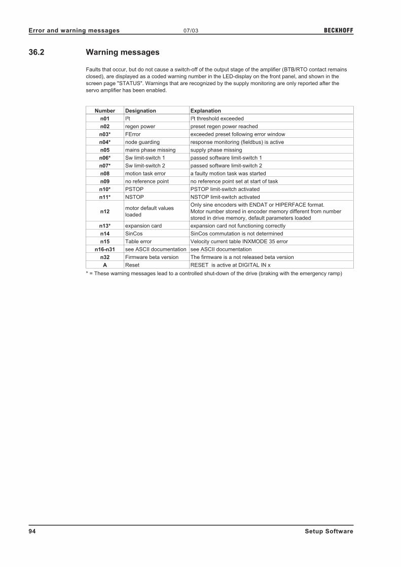
36.2 Warning messages
Faults that occur, but do not cause a switch-off of the output stage of the amplifier (BTB/RTO contact remains
closed), are displayed as a coded warning number in the LED-display on the front panel, and shown in the
screen page "STATUS". Warnings that are recognized by the supply monitoring are only reported after the
servo amplifier has been enabled.
Number Designation Explanation
n01 I²t I²t threshold exceeded
n02 regen power preset regen power reached
n03* FError exceeded preset following error window
n04* node guarding response monitoring (fieldbus) is active
n05 mains phase missing supply phase missing
n06* Sw limit-switch 1 passed software limit-switch 1
n07* Sw limit-switch 2 passed software limit-switch 2
n08 motion task error a faulty motion task was started
n09 no reference point no reference point set at start of task
n10* PSTOP PSTOP limit-switch activated
n11* NSTOP NSTOP limit-switch activated
n12motor default values
loaded
Only sine encoders with ENDAT or HIPERFACE format.
Motor number stored in encoder memory different from number
stored in drive memory, default parameters loaded
n13* expansion card expansion card not functioning correctly
n14 SinCos SinCos commutation is not determined
n15 Table error Velocity current table INXMODE 35 error
n16-n31 see ASCII documentation see ASCII documentation
n32 Firmware beta version The firmware is a not released beta version
A Reset RESET is active at DIGITAL IN x
* = These warning messages lead to a controlled shut-down of the drive (braking with the emergency ramp)
94 Setup Software
Error and warning messages 07/03 BECKHOFF

37 Trouble-Shooting
The following table should be understood as a "First-aid" box. There may be a wide variety of causes of any
fault that occurs, depending on the conditions in your system. In multi-axis systems there may be further hidden
causes of a fault.
Our applications department can give you further assistance with problems.
Fault Possible causes Measures to remove the cause of the fault
Fault message
communication fault
— wrong cable used
— cable plugged into wrong socket of
the servo amplifier or PC
— wrong PC interface selected
— use a null-modem cable
— plug the cable into the correct
socket of the servo amplifier or PC
— select the correct interface
Motor doesn't rotate
— amplifier disabled
— analog setpoint failed
— Motor phases swapped
— Brake not released
— drive is mechanically blocked
— Motor pole number set incorrectly
— Feedback set up incorrectly
— current limit activated (analog or digital I/O)
— apply enable signal
— check PLC-program and cable
— correct motor phase sequence
— check cable and inverse diode
— check drive
— correct setting
— correct feedback setting
— correct current limitation
Motor oscillates
— Gain KP too high
— Interference in feedback system
— Analog-GND (AGND) is not
connected with the analog setpoint sources
— reduce KP (speed contr.)
— replace the feedback cable
— connect AGND with setpoint
source
Motor runs too soft
— Integral time Tn too high
— Gain KP too low
— PID-T2 too high
— T-Tacho too high
— reduce Tn (speed contr.)
— increase KP (speed contr.)
— reduce PID-T2
— reduce T-Tacho
Motor runs roughly
— Integral time Tn too low
— Gain KP too high
— PID-T2 too low
— T-Tacho too low
— increase Tn (speed contr.)
— reduce KP (speed contr.)
— increase PID-T2
— increase T-Tacho
Setup Software 95
BECKHOFF 07/03 Trouble-Shooting

38 Related Documents
All the documents listed below can be found on the documentation CD-ROM.
� Installation manual
� CANopen manual
� PROFIBUS manual
� SERCOS manual
� Application note Emergency Stop
� Manuals for several motor series
96 Setup Software
Related Documents 07/03 BECKHOFF

39 Glossary
C Clock clock signal
Common-mode voltage the disturbance amplitude that can be compensated for by a differential analog input
Continuous power of the regen circuit the average power that can be dissipated in the regen circuit
Counts internal count pulses, 1 pulse = 1/220
turn-1
Current controllerregulates the difference between the current setpoint and the actual current to 0.
Output: power-output voltage
D DC-link (bus) voltage rectified and smoothed power voltage
Disable removal of the ENABLE signal (0V or open)
E EEPROMelectrically erasable memory in the servo amplifier, data that are stored in the
EEPROM are not lost if the auxiliary voltage is switched off
Enable the enable signal for the servo amplifier (+24V)
Earth short electrically conductive connection between a phase and PE
F speed limit maximal value for the speed normalization at ±10V
G GRAY-code a special way of representing binary numbers
H Holding brake a brake in the motor, that can only be applied when the motor is at standstill
I I²t threshold monitoring of the r.m.s. current that is actually drawn
Incremental encoder interfaceposition indication through 2 signals with a 90° phase difference, not an absolute
position output
Ipeak, peak current the r.m.s. value of the pulse current
Irms, r.m.s. current the r.m.s. value of a steady current
K KP, P-gain proportional gain of a control loop
L Limit-switchto limit the range of movement of the machine; implemented as an n.c. (break)
contact
M Machinethe total assembly of parts or devices that are connected together, of which at least
one is movable
Monitor output output of an analog measurement
Motion blocka packet of data containing all the position parameters that are required for a motion
task
Multi-axis system a machine with several independent drive axes
O Optocoupler optical connection between two electrically independent systems
P P controller a control loop that has purely proportional response
Phase shiftcompensation for the lag between the electromagnetic and the magnetic field in the
motor
PID controller control loop with proportional, integral and differential response
PID-T2 filter time constant for the speed controller output
Position controllerregulates the difference between the position setpoint and the actual position to 0.
Output: speed setpoint
Pulse power of the regen circuit the maximum power that can be handled by the regen circuit
R RAMvolatile memory in the servo amplifier. Data that are stored in the RAM are lost when
the auxiliary voltage is switched off.
Regen circuitconverts superfluous (regenerative) energy that is fed back by the motor, during
braking, into heat in the regen resistor.
Reset new start of the microprocessor
Reversing mode operating with a periodic change of direction
ROD interface incremental position output
S Servo amplifier an instrument for controlling the torque, speed and position of a servomotor
Short-circuit here: electrically conductive connection between two phases
Speed controllerregulates the difference between the speed setpoint SW and the actual speed to 0.
Output: current setpoint
SSI interface cyclically absolute, serial position output
Setp. ramps limiting of the rate of change of the speed setpoint value
T Tacho voltage a voltage proportional to the actual speed
T-tacho, tacho time constant filter time constant in the speed feedback of the control loop
Tn, integration time integral component of the control loop
Z Zero pulse/mark is produced by incremental encoders, once per turn, used to zero the machine
Setup Software 97
BECKHOFF 07/03 Glossary

40 Motor Numbers
Motor type Online-Name Number
6SM100K-3000 6SM100K3000 131
6SM100K-3000-BV 6SM100K30BV 133
6SM100L-3000 6SM100L3000 143
6SM100L-3000-BV 6SM100L30BV 145
6SM100M-3000 6SM100M3000 139
6SM100M-3000-BV 6SM100M30BV 141
6SM100S-3000 6SM100S3000 135
6SM100S-3000-BV 6SM100S30BV 137
6SM107K-3000 6SM107K3000 19
6SM107S-3000 6SM107S3000 21
6SM109L-3000 6SM109L30 538
6SM109LB-2000 6SM109LB20 540
6SM109M-3000 6SM109M30 536
6SM27LL-4500 6SM27LL4500 29
6SM27M-4000 6SM27M4000 1
6SM37L-4000 6SM37L4000 7
6SM37M-6000 6SM37M6000 5
6SM37S-6000 6SM37S6000 3
6SM37VL-6000 6SM37VL6000 23
6SM45L-3000 6SM45L3000 105
6SM45M-3000 6SM45M3000 103
6SM45S-3000 6SM45S3000 101
6SM47L-3000 6SM47L3000 9
6SM56L-3000 6SM56L3000 115
6SM56L-3000-BV 6SM56L30BV 117
6SM56M-3000 6SM56M3000 111
6SM56M-3000-BV 6SM56M30BV 113
6SM56S-3000 6SM56S3000 107
6SM56S-3000-BV 6SM56S30BV 109
6SM57L-3000 6SM57L3000 27
6SM57M-3000 6SM57M3000 13
6SM57S-3000 6SM57S3000 11
6SM71K-3000 6SM71K3000 119
6SM71K-3000-BV 6SM71K30BV 121
6SM71M-3000 6SM71M3000 127
6SM71M-3000-BV 6SM71M30BV 129
6SM71S-3000 6SM71S3000 123
6SM71S-3000-BV 6SM71S30BV 125
6SM77K-3000 6SM77K3000 15
6SM77S-3000 6SM77S3000 17
BH-122-A BH122A 521
BH-124-B BH124B 522
BH-126-B BH126B 512
BH-222-B BH222B 527
BH-224-B BH224B 528
BH-226-C BH226C 513
BH-226-E BH226E 523
BH-422-D BH422D 526
BH-424-B BH424B 502
BH-424-D BH424D 524
BH-426-B BH426B 514
BH-426-D BH426D 529
BH-426-H BH426H 535
BH-622-B BH622B 525
BH-624-C BH624C 530
BH-624-D BH624D 504
BH-626-E BH626E 531
BH-822-D BH822D 532
BH-824-A BH824A 509
BH-824-D BH824D 533
BH-826-C BH826C 534
BH-826-D BH826D 510
BH-828-B BH828B 511
98 Setup Software
Motor Numbers 07/03 BECKHOFF

Motor series
DBL/DBKonline name
Number
(in preparation)
R=Resolver
E=Encoder
DBK4N00100 DBK4N00100 00259R/E
DBK4N00160 DBK4N00160 00441R/E
DBK5N00210 DBK5N00210 00374R/E
DBL1X00010 DBL1X00010 00647R/E
DBL1X00020 DBL1X00020 00670R/E
DBL2H00040 DBL2H00040 00288R/E
DBL2H00060 DBL2H00060 00558R/E
DBL2H00080 DBL2H00080 00293R/E
DBL2M00080 DBL2M00080 00348R/E
DBL3H00065 DBL3H00065 00276R/E
DBL3H00130 DBL3H00130 00275R/E
DBL3M00190 DBL3M00190 00263R/E
DBL3N00065 DBL3N00065 00299R/E
DBL3N00130 DBL3N00130 00258R/E
DBK4H00100 DBK4H00100 00017R/E
DBK4H00160 DBK4H00160 00347R/E
DBK5N00430 DBK5N00430 00375R/E
DBK6N00350 DBK6N00350 00376R/E
DBL3H00250 DBL3H00250 00420R/E
DBL3N00300 DBL3N00300 00252R/E
DBL4H00260 DBL4H00260 00285R/E
DBL4N00260 DBL4N00260 00301R/E
DBL4N00530 DBL4N00530 00253R/E
DBK5H00210 DBK5H00210 00549R/E
DBK5H00430 DBK5H00430 00345R/E
DBK6N00700 DBK6N00700 00356R/E
DBK7N00650 DBK7N00650 00377R/E
DBL4H00530 DBL4H00530 00284R/E
DBL4N00750 DBL4N00750 00254R/E
DBL4N00950 DBL4N00950 00470R/E
DBL5N01050 DBL5N01050 00666R/E
DBK7N01200 DBK7N01200 00378R/E
DBL4H00750 DBL4H00750 00609R/E
DBL5N01350 DBL5N01350 00633R/E
DBL5N01700 DBL5N01700 00665R/E
DBK7N01950 DBK7N01950 00379R/E
DBL5H01050 DBL5H01050 00562R/E
DBL5N02200 DBL5N02200 00620R/E
DBL5H01350 DBL5H01350 00576R/E
DBL5H01700 DBL5H01700 00661R/E
DBL6N02200 DBL6N02200 00332R/E
DBL6N02900 DBL6N02900 00407R/E
DBL7N02600 DBL7N02600 00335R/E
DBL7N03200 DBL7N03200 00402R/E
DBL7N04000 DBL7N04000 00450R/E
Setup Software 99
BECKHOFF 07/03 Motor Numbers

41 Index
! ? . . . . . . . . . . . . . . . . . . . . . . . . 24
A abbreviations . . . . . . . . . . . . . . . . . . 7
accel./decel. . . . . . . . . . . . . . . . . . . 73Acceleration . . . . . . . . . . . . . . . . . . 31Acceleration Feedforward . . . . . . . . . . . 37acceleration ramp . . . . . . . . . . . . . . . 65actual current. . . . . . . . . . . . . . . . . . 81actual errors . . . . . . . . . . . . . . . . . . 80actual speed . . . . . . . . . . . . . . . . . . 81Actual warnings . . . . . . . . . . . . . . . . 80Address . . . . . . . . . . . . . . . . . . . . 30Address (SERCOS) . . . . . . . . . . . . . . 90Analog In 1/2
actual value . . . . . . . . . . . . . . . . 81Analog Inputs . . . . . . . . . . . . . . . . . 40Analog outputs . . . . . . . . . . . . . . . . . 43angle of rotation . . . . . . . . . . . . . . . . 81ASCII-command
ACC . . . . . . . . . . . . . . . . . . . . 53ACCR . . . . . . . . . . . . . . . . . . . 65ACCUNIT . . . . . . . . . . . . . . . . . 31ADDR . . . . . . . . . . . . . . . . . . . 30ADDR (SERCOS) . . . . . . . . . . . . . 90ADDRFB . . . . . . . . . . . . . . . . . . 30AENA . . . . . . . . . . . . . . . . . . . 30ALIAS . . . . . . . . . . . . . . . . . . . 30ANCNFG. . . . . . . . . . . . . . . . . . 41ANDB . . . . . . . . . . . . . . . . . . . 40ANIN1 . . . . . . . . . . . . . . . . . . . 81ANIN2 . . . . . . . . . . . . . . . . . . . 81ANOFFx . . . . . . . . . . . . . . . . . . 40ANOUT. . . . . . . . . . . . . . . . . . . 43ANZEROx . . . . . . . . . . . . . . . . . 40AVZ1 . . . . . . . . . . . . . . . . . . . . 40CBAUD. . . . . . . . . . . . . . . . . . . 30CLRFAULT. . . . . . . . . . . . . . . . . 80COLDSTART . . . . . . . . . . . . . . . 26DEC . . . . . . . . . . . . . . . . . . . . 53DECDIS . . . . . . . . . . . . . . . . . . 54DECR . . . . . . . . . . . . . . . . . . . 65DECSTOP . . . . . . . . . . . . . . . . . 54DIR. . . . . . . . . . . . . . . . . . . . . 53DIS . . . . . . . . . . . . . . . . . . . . . 27DREF . . . . . . . . . . . . . . . . . . . 65EN . . . . . . . . . . . . . . . . . . . . . 27ENCLINES . . . . . . . . . . . . . . . . . 37ENCOUT. . . . . . . . . . . . . . . . . . 39ENCZERO . . . . . . . . . . . . . . . . . 39ERND . . . . . . . . . . . . . . . . . . . 67ERRCODE . . . . . . . . . . . . . . . . . 80EXTPOS (P) . . . . . . . . . . . . . . . . 56EXTPOS (PI). . . . . . . . . . . . . . . . 55EXTWD . . . . . . . . . . . . . . . . . . 30FBTYPE . . . . . . . . . . . . . . . . . . 36FILTMODE. . . . . . . . . . . . . . . . . 37FLTCNT . . . . . . . . . . . . . . . . . . 80FLTHIST . . . . . . . . . . . . . . . . . . 80GF (async) . . . . . . . . . . . . . . . . . 35GFTN (async) . . . . . . . . . . . . . . . 35GP (P) . . . . . . . . . . . . . . . . . . . 56GP (PI) . . . . . . . . . . . . . . . . . . . 55GPFFV (P) . . . . . . . . . . . . . . . . . 56GPFFV (PI) . . . . . . . . . . . . . . . . 55GPTN . . . . . . . . . . . . . . . . . . . 55GPV . . . . . . . . . . . . . . . . . . . . 55GV . . . . . . . . . . . . . . . . . . . . . 54GVFBT . . . . . . . . . . . . . . . . . . . 54GVFR . . . . . . . . . . . . . . . . . . . 54GVT2. . . . . . . . . . . . . . . . . . . . 54GVTN . . . . . . . . . . . . . . . . . . . 54HVER . . . . . . . . . . . . . . . . . . . 29I . . . . . . . . . . . . . . . . . . . . . . 81I2T . . . . . . . . . . . . . . . . . . . . . 81I2TLIM . . . . . . . . . . . . . . . . . . . 52
ICONT . . . . . . . . . . . . . . . . . . . 52ID. . . . . . . . . . . . . . . . . . . . . . 81IPEAK . . . . . . . . . . . . . . . . . . . 52IQ . . . . . . . . . . . . . . . . . . . . . 81ISCALEx . . . . . . . . . . . . . . . . . . 40KTN . . . . . . . . . . . . . . . . . . . . 52L (sync) . . . . . . . . . . . . . . . . . . 32MBRAKE (async) . . . . . . . . . . . . . 35MBRAKE (sync) . . . . . . . . . . . . . . 32MCFW (async) . . . . . . . . . . . . . . . 35MCTR (async) . . . . . . . . . . . . . . . 35MH . . . . . . . . . . . . . . . . . . . . . 57MICONT (async) . . . . . . . . . . . . . . 34MICONT (sync) . . . . . . . . . . . . . . 32MIMR (async) . . . . . . . . . . . . . . . 35MIPEAK (async) . . . . . . . . . . . . . . 34MIPEAK (sync). . . . . . . . . . . . . . . 32MJOG . . . . . . . . . . . . . . . . . . . 65MLGQ . . . . . . . . . . . . . . . . . . . 52MNAME (async) . . . . . . . . . . . . . . 34MNAME (sync) . . . . . . . . . . . . . . . 32MNUMBER (async) . . . . . . . . . . . . 34MNUMBER (sync) . . . . . . . . . . . . . 32MOVE . . . . . . . . . . . . . . . . . . . 66MPHASE. . . . . . . . . . . . . . . . . . 37MPOLES (async) . . . . . . . . . . . . . 34MPOLES (sync) . . . . . . . . . . . . . . 32MRESBW . . . . . . . . . . . . . . . . . 37MRESPOLES . . . . . . . . . . . . . . . 37MSPEED (async) . . . . . . . . . . . . . 34MSPEED (sync) . . . . . . . . . . . . . . 32MTANGLP (sync) . . . . . . . . . . . . . 33MTR (async) . . . . . . . . . . . . . . . . 34MTYPE (async) . . . . . . . . . . . . . . 34MTYPE (sync) . . . . . . . . . . . . . . . 32MUNIT (async) . . . . . . . . . . . . . . . 35MUNIT (sync) . . . . . . . . . . . . . . . 33MVANGLB (sync) . . . . . . . . . . . . . 33MVANGLF (sync) . . . . . . . . . . . . . 33MVR (async) . . . . . . . . . . . . . . . . 34NREF . . . . . . . . . . . . . . . . . . . 58OPMODE . . . . . . . . . . . . . . . . . 27PBAL. . . . . . . . . . . . . . . . . . . . 81PBALMAX . . . . . . . . . . . . . . . . . 29PBALRES . . . . . . . . . . . . . . . . . 29PE . . . . . . . . . . . . . . . . . . . . . 81PEINPOS . . . . . . . . . . . . . . . . . 67PEMAX (P). . . . . . . . . . . . . . . . . 56PEMAX (PI) . . . . . . . . . . . . . . . . 55PFB . . . . . . . . . . . . . . . . . . . . 81PGEARI . . . . . . . . . . . . . . . . . . 69PGEARO. . . . . . . . . . . . . . . . . . 69PMODE . . . . . . . . . . . . . . . . . . 29POSCNFG . . . . . . . . . . . . . . . . . 67PRD . . . . . . . . . . . . . . . . . . . . 81PTMIN . . . . . . . . . . . . . . . . . . . 67PVMAX . . . . . . . . . . . . . . . . . . 67REFIP . . . . . . . . . . . . . . . . . . . 52ROFFS. . . . . . . . . . . . . . . . . . . 65SAVE . . . . . . . . . . . . . . . . . . . 26SBAUD. . . . . . . . . . . . . . . . . . . 90SERIALNO. . . . . . . . . . . . . . . . . 29SLEN. . . . . . . . . . . . . . . . . . . . 90SPHAS. . . . . . . . . . . . . . . . . . . 90SRND . . . . . . . . . . . . . . . . . . . 67SSIGRAY . . . . . . . . . . . . . . . . . 39SSIINV . . . . . . . . . . . . . . . . . . . 39SSIMODE . . . . . . . . . . . . . . . . . 39SSIOUT . . . . . . . . . . . . . . . . . . 39SSTAT . . . . . . . . . . . . . . . . . . . 90STATCODE . . . . . . . . . . . . . . . . 80STOP . . . . . . . . . . . . . . . . . . . 66SWCNFG . . . . . . . . . . . . . . . . . 68SWEx . . . . . . . . . . . . . . . . . . . 68
100 Setup Software
Index 07/03 BECKHOFF

TEMPE. . . . . . . . . . . . . . . . . . . 81TEMPH. . . . . . . . . . . . . . . . . . . 81TRUN . . . . . . . . . . . . . . . . . . . 30V . . . . . . . . . . . . . . . . . . . . . . 81VBUS . . . . . . . . . . . . . . . . . . . 81VBUSBAL . . . . . . . . . . . . . . . . . 29VCMD . . . . . . . . . . . . . . . . . . . 81VER . . . . . . . . . . . . . . . . . . . . 29VJOG . . . . . . . . . . . . . . . . . . . 65VLIM . . . . . . . . . . . . . . . . . . . . 53VLO . . . . . . . . . . . . . . . . . . . . 37VOSPD. . . . . . . . . . . . . . . . . . . 54VREF. . . . . . . . . . . . . . . . . . . . 65VSCALEx . . . . . . . . . . . . . . . . . 40
Auto Enable . . . . . . . . . . . . . . . . . . 30Auto-Offset, setpoints . . . . . . . . . . . . . 40axis type . . . . . . . . . . . . . . . . . . . . 67
B Bandwidth Resolver . . . . . . . . . . . . . . 37
Baud Rate (SERCOS) . . . . . . . . . . . . . 90Baudrate . . . . . . . . . . . . . . . . . . . . 30brake (async). . . . . . . . . . . . . . . . . . 35brake (sync) . . . . . . . . . . . . . . . . . . 32bus voltage (DC-link) . . . . . . . . . . . . . . 81
C Cancel
recording . . . . . . . . . . . . . . . . . . 82channel . . . . . . . . . . . . . . . . . . . . . 82Clearfault allow coldstart (Sercos) . . . . . . . 91close . . . . . . . . . . . . . . . . . . . . . . 24COM1, 2, 3, 4 . . . . . . . . . . . . . . . . . 25command, terminal . . . . . . . . . . . . . . . 86Communication . . . . . . . . . . . . . . . . 24current advance (sync) . . . . . . . . . . . . . 33current component D. . . . . . . . . . . . . . 81current component Q. . . . . . . . . . . . . . 81Cursor-function. . . . . . . . . . . . . . . . . 83
D DC-link voltage . . . . . . . . . . . . . . . . . 81
DC-Link>x . . . . . . . . . . . . . . . . . . . 51DC-Linkxxx . . . . . . . . . . . . . . . . . . . 51dead band . . . . . . . . . . . . . . . . . . . 40deceleration ramp . . . . . . . . . . . . . . . 65Default settings. . . . . . . . . . . . . . . . . 83delay time . . . . . . . . . . . . . . . . . . . 73digital inputs . . . . . . . . . . . . . . . . . . 44digital outputs . . . . . . . . . . . . . . . . . 49direction of motion . . . . . . . . . . . . . . . 65Disable . . . . . . . . . . . . . . . . . . . . . 27Disconnect interfaces . . . . . . . . . . . . . 25
E Edit . . . . . . . . . . . . . . . . . . . . . . . 24
effective current (Irms) . . . . . . . . . . . . . 52EL 7 Read Error (SERCOS) . . . . . . . . . . 91EL7 Dec/Hex (SERCOS). . . . . . . . . . . . 91emergency ramp . . . . . . . . . . . . . . . . 54Emergency Stop . . . . . . . . . . . . . . . . 48ENABLE
message . . . . . . . . . . . . . . . . . . 51switch . . . . . . . . . . . . . . . . . . . 27
Enclines . . . . . . . . . . . . . . . . . . . . 37Encoder emulation . . . . . . . . . . . . . . . 38EOT consequence (Sercos) . . . . . . . . . . 91Error . . . . . . . . . . . . . . . . . . . . . . 51error messages . . . . . . . . . . . . . . . . 93Error/Warn . . . . . . . . . . . . . . . . . . . 51Exit . . . . . . . . . . . . . . . . . . . . . . . 27Ext. WD . . . . . . . . . . . . . . . . . . . . 30
F fault-frequency . . . . . . . . . . . . . . . . . 80
Feedback Type. . . . . . . . . . . . . . . . . 36Feedback, actual speed filter . . . . . . . . . 54FError . . . . . . . . . . . . . . . . . . . . . 51FError_clear . . . . . . . . . . . . . . . . . . 46Ff (P) . . . . . . . . . . . . . . . . . . . . . . 56Ff (PI) . . . . . . . . . . . . . . . . . . . . . 55Field Correct Factor (async) . . . . . . . . . . 35Field Level (async) . . . . . . . . . . . . . . . 35Fieldbus-Address . . . . . . . . . . . . . . . 30Firmware . . . . . . . . . . . . . . . . . . . . 29Following Error
actual value . . . . . . . . . . . . . . . . 81following error (P) . . . . . . . . . . . . . . . 56following error (PI) . . . . . . . . . . . . . . . 55FStart2 Nr x . . . . . . . . . . . . . . . . . . 47function keys . . . . . . . . . . . . . . . . . . 15
G gearing mode . . . . . . . . . . . . . . . . . 79
glossary . . . . . . . . . . . . . . . . . . . . 97
H Hardware. . . . . . . . . . . . . . . . . . . . 29
hardware requirements. . . . . . . . . . . . . 12heat sink temperature . . . . . . . . . . . . . 81homing . . . . . . . . . . . . . . . . . . . . . 57homing 1 . . . . . . . . . . . . . . . . . . . . 59homing 2 . . . . . . . . . . . . . . . . . . . . 60homing 3 . . . . . . . . . . . . . . . . . . . . 61homing 4 . . . . . . . . . . . . . . . . . . . . 62homing 5 . . . . . . . . . . . . . . . . . . . . 63homing 7 . . . . . . . . . . . . . . . . . . . . 64
I I/O-Expansion
A0-A7 . . . . . . . . . . . . . . . . . . . 92FError . . . . . . . . . . . . . . . . . . . 92FError_clear . . . . . . . . . . . . . . . . 92InPos. . . . . . . . . . . . . . . . . . . . 92MT_Restart . . . . . . . . . . . . . . . . 92Next-InPos . . . . . . . . . . . . . . . . . 92PosReg . . . . . . . . . . . . . . . . . . 92Reference . . . . . . . . . . . . . . . . . 92Start_Jog v=x . . . . . . . . . . . . . . . 92Start_MT Next . . . . . . . . . . . . . . . 92Start_MT No. x . . . . . . . . . . . . . . . 92
I_act>x . . . . . . . . . . . . . . . . . . . . . 50I_actxxx . . . . . . . . . . . . . . . . . . . . 50I²t
actual value . . . . . . . . . . . . . . . . 81message . . . . . . . . . . . . . . . . . . 51threshold . . . . . . . . . . . . . . . . . . 52
inductance . . . . . . . . . . . . . . . . . . . 32InPos . . . . . . . . . . . . . . . . . . . . . . 50InPosition. . . . . . . . . . . . . . . . . . . . 67Installation . . . . . . . . . . . . . . . . . . . 14internal temperature . . . . . . . . . . . . . . 81Intg.Off . . . . . . . . . . . . . . . . . . . . . 46Io . . . . . . . . . . . . . . . . . . . . . . . . 34Io (sync) . . . . . . . . . . . . . . . . . . . . 32Iomax (async) . . . . . . . . . . . . . . . . . 34Iomax (sync) . . . . . . . . . . . . . . . . . . 32Ipeak2 x . . . . . . . . . . . . . . . . . . . . 46
J jog mode . . . . . . . . . . . . . . . . . . . . 65
K KP
current contr. . . . . . . . . . . . . . . . . 52position/speed contr. (PI) . . . . . . . . . 55speed contr. . . . . . . . . . . . . . . . . 54
Kp (async) . . . . . . . . . . . . . . . . . . . 35KV (P) . . . . . . . . . . . . . . . . . . . . . 56KV (PI) . . . . . . . . . . . . . . . . . . . . . 55
L L (sync). . . . . . . . . . . . . . . . . . . . . 32
last 10 faults . . . . . . . . . . . . . . . . . . 80Limit Phi (sync) . . . . . . . . . . . . . . . . . 33Load
recording . . . . . . . . . . . . . . . . . . 82Load Data from Disk (async) . . . . . . . . . . 35Load Data from disk (sync) . . . . . . . . . . 33Load from disk . . . . . . . . . . . . . . . . . 26LWL-Length (SERCOS) . . . . . . . . . . . . 90
Setup Software 101
BECKHOFF 07/03 Index

M Mains phase missing. . . . . . . . . . . . . . 29
mains voltage max. . . . . . . . . . . . . . . 29mains-RTO . . . . . . . . . . . . . . . . . . . 50max. speed (async) . . . . . . . . . . . . . . 34max. speed (sync) . . . . . . . . . . . . . . . 32Mem . . . . . . . . . . . . . . . . . . . . . . 82menu bar . . . . . . . . . . . . . . . . . . . . 24Mode/Position Feedback (P) . . . . . . . . . . 56Mode/Position Feedback (PI) . . . . . . . . . 55Modulo-End-Pos.. . . . . . . . . . . . . . . . 67Modulo-Start-Pos. . . . . . . . . . . . . . . . 67Monitor1/2 . . . . . . . . . . . . . . . . . . . 43Motion task table . . . . . . . . . . . . . . . . 66motion task, number . . . . . . . . . . . . . . 66Motor numbers . . . . . . . . . . . . . . . . . 98Motor Unit (async) . . . . . . . . . . . . . . . 35Motor Unit (sync) . . . . . . . . . . . . . . . . 33Motorname (async). . . . . . . . . . . . . . . 34Motorname (sync) . . . . . . . . . . . . . . . 32Motornumber (async) . . . . . . . . . . . . . 34Motornumber (sync) . . . . . . . . . . . . . . 32MT Restart . . . . . . . . . . . . . . . . . . . 47MT_No_Bit . . . . . . . . . . . . . . . . . . . 46
N Name. . . . . . . . . . . . . . . . . . . . . . 30
next motion task . . . . . . . . . . . . . . . . 73next number . . . . . . . . . . . . . . . . . . 73Next-InPos . . . . . . . . . . . . . . . . . . . 51NSTOP . . . . . . . . . . . . . . . . . . . . . 45number of the motion task . . . . . . . . . . . 66
O Offline . . . . . . . . . . . . . . . . . . . . . 25
OffsetAuto-Offset . . . . . . . . . . . . . . . . . 40Encoder . . . . . . . . . . . . . . . . . . 37Resolver . . . . . . . . . . . . . . . . . . 37setpoint . . . . . . . . . . . . . . . . . . 40Zero pulse, ROD . . . . . . . . . . . . . . 39
open . . . . . . . . . . . . . . . . . . . . . . 24Operating systems . . . . . . . . . . . . . . . 12operation . . . . . . . . . . . . . . . . . . . . 14OPMODE . . . . . . . . . . . . . . . . . . . 27Opmode A/B . . . . . . . . . . . . . . . . . . 47oscilloscope . . . . . . . . . . . . . . . . . . 82overspeed . . . . . . . . . . . . . . . . . . . 54
P PC cable . . . . . . . . . . . . . . . . . . . . 13
PC connection . . . . . . . . . . . . . . . . . 13PC software . . . . . . . . . . . . . . . . . . 29Peak current
Iomax (async) . . . . . . . . . . . . . . . 34Iomax (sync) . . . . . . . . . . . . . . . . 32Ipeak . . . . . . . . . . . . . . . . . . . . 52Ref.-Ipeak . . . . . . . . . . . . . . . . . 52
Phase (SERCOS) . . . . . . . . . . . . . . . 90PID-T2 . . . . . . . . . . . . . . . . . . . . . 54PI-PLUS . . . . . . . . . . . . . . . . . . . . 54poles
motor (async) . . . . . . . . . . . . . . . 34motor (sync) . . . . . . . . . . . . . . . . 32Resolver . . . . . . . . . . . . . . . . . . 37
Pos latch . . . . . . . . . . . . . . . . . . . . 47Pos.>x . . . . . . . . . . . . . . . . . . . . . 50Position. . . . . . . . . . . . . . . . . . . . . 31
actual value . . . . . . . . . . . . . . . . 81Position polarity (Sercos) . . . . . . . . . . . 91position register . . . . . . . . . . . . . . . . 68Posreg0 . . . . . . . . . . . . . . . . . . . . 51Posreg1-4 . . . . . . . . . . . . . . . . . . . 51Posreg5 . . . . . . . . . . . . . . . . . . . . 51prescribed use. . . . . . . . . . . . . . . . . . 6print . . . . . . . . . . . . . . . . . . . . . . 24print preview / print setup . . . . . . . . . . . 24Product Sercos Settings . . . . . . . . . . . . 91PSTOP . . . . . . . . . . . . . . . . . . . . . 45
R ramp . . . . . . . . . . . . . . . . . . . . . . 72
Rated Speed (async). . . . . . . . . . . . . . 34ratio . . . . . . . . . . . . . . . . . . . . . . 79READ IDN (SERCOS) . . . . . . . . . . . . . 91Read List Item (SERCOS) . . . . . . . . . . . 91Ref_OK, digital output . . . . . . . . . . . . . 51reference offset . . . . . . . . . . . . . . . . 65Reference point
actual value . . . . . . . . . . . . . . . . 81reference traverse . . . . . . . . . . . . . . . 58reference traverse (homing) . . . . . . . . . . 57Reference, digital input. . . . . . . . . . . . . 46regen off . . . . . . . . . . . . . . . . . . . . 50regen power
actual value . . . . . . . . . . . . . . . . 81setting . . . . . . . . . . . . . . . . . . . 29
Regen resistor . . . . . . . . . . . . . . . . . 29reset
Input . . . . . . . . . . . . . . . . . . . . 45switch . . . . . . . . . . . . . . . . . . . 80
resolutionoscilloscope . . . . . . . . . . . . . . . . 82position data . . . . . . . . . . . . . . . . 69
Resolver . . . . . . . . . . . . . . . . . . . . 37Bandwidth . . . . . . . . . . . . . . . . . 37no. of poles . . . . . . . . . . . . . . . . 37Offset. . . . . . . . . . . . . . . . . . . . 37
RODNI-Offset . . . . . . . . . . . . . . . . . . 39Resolution . . . . . . . . . . . . . . . . . 38
ROD/SSI . . . . . . . . . . . . . . . . . . . . 46ROD-Interpolation . . . . . . . . . . . . . . . 39Rotary Direction . . . . . . . . . . . . . . . . 53Rotor time constant . . . . . . . . . . . . . . 34RS232/PC, interface . . . . . . . . . . . . . . 13run time
status . . . . . . . . . . . . . . . . . . . 80Run time . . . . . . . . . . . . . . . . . . . . 30
S s_cmd . . . . . . . . . . . . . . . . . . . . . 71
save . . . . . . . . . . . . . . . . . . . . . . 24Save
recording . . . . . . . . . . . . . . . . . . 82save as . . . . . . . . . . . . . . . . . . . . . 24Save to disk . . . . . . . . . . . . . . . . . . 26save to EEPROM . . . . . . . . . . . . . . . 26scaling, setpoints . . . . . . . . . . . . . . . . 40screen layout . . . . . . . . . . . . . . . . . . 23screen page
actual values . . . . . . . . . . . . . . . . 81amplifier . . . . . . . . . . . . . . . . . . 26analog I/O . . . . . . . . . . . . . . . . . 40basic setup. . . . . . . . . . . . . . . . . 29Bode Plot . . . . . . . . . . . . . . . . . 85communication . . . . . . . . . . . . . . . 25current . . . . . . . . . . . . . . . . . . . 52digital I/O. . . . . . . . . . . . . . . . . . 44encoder . . . . . . . . . . . . . . . . . . 38feedback . . . . . . . . . . . . . . . . . . 36gearing . . . . . . . . . . . . . . . . . . . 79homing . . . . . . . . . . . . . . . . . . . 57I/O expansion . . . . . . . . . . . . . . . 92Input service parameters . . . . . . . . . 84motion task parameters . . . . . . . . . . 70motor . . . . . . . . . . . . . . . . . . . . 34motor (sync) . . . . . . . . . . . . . . . . 32oscilloscope . . . . . . . . . . . . . . . . 82position (P) . . . . . . . . . . . . . . . . . 56position (PI) . . . . . . . . . . . . . . . . 55position data . . . . . . . . . . . . . . . . 66PROFIBUS. . . . . . . . . . . . . . . . . 87PROFIBUS instrument control . . . . . . . 88SERCOS. . . . . . . . . . . . . . . . . . 90SERCOS Service . . . . . . . . . . . . . 91speed . . . . . . . . . . . . . . . . . . . 53status . . . . . . . . . . . . . . . . . . . 80terminal . . . . . . . . . . . . . . . . . . 86
102 Setup Software
Index 07/03 BECKHOFF

Serial number . . . . . . . . . . . . . . . . . 29service . . . . . . . . . . . . . . . . . . . . . 84service functions . . . . . . . . . . . . . . . . 83
direct current . . . . . . . . . . . . . . . . 83motion task. . . . . . . . . . . . . . . . . 83reversing mode . . . . . . . . . . . . . . 83speed . . . . . . . . . . . . . . . . . . . 83torque . . . . . . . . . . . . . . . . . . . 83Zero . . . . . . . . . . . . . . . . . . . . 83
service parameters . . . . . . . . . . . . . . . 84Service, menu bar . . . . . . . . . . . . . . . 24Setp. ramp– . . . . . . . . . . . . . . . . . . 53Setp. ramp+ . . . . . . . . . . . . . . . . . . 53Setp.-functions . . . . . . . . . . . . . . . . . 41SETUP.EXE . . . . . . . . . . . . . . . . . . 14Single Turn/Multi Turn . . . . . . . . . . . . . 39Slip Correct Factor (async). . . . . . . . . . . 35Slot, Extension x . . . . . . . . . . . . . . . . 27software limit-switches
position register . . . . . . . . . . . . . . 68Sw_limit . . . . . . . . . . . . . . . . . . 50
speed limit . . . . . . . . . . . . . . . . . . . 53speed setpoint . . . . . . . . . . . . . . . . . 81SSI
Baudrate . . . . . . . . . . . . . . . . . . 39SSI-Clock . . . . . . . . . . . . . . . . . 39SSI-Code. . . . . . . . . . . . . . . . . . 39
Standard Sercos Settings . . . . . . . . . . . 91standstill current . . . . . . . . . . . . . . . . 32standstill current (async) . . . . . . . . . . . . 34start
homing . . . . . . . . . . . . . . . . . . . 57jog mode . . . . . . . . . . . . . . . . . . 65motion task. . . . . . . . . . . . . . . . . 66recording . . . . . . . . . . . . . . . . . . 82service function . . . . . . . . . . . . . . 83
start by I/O edge . . . . . . . . . . . . . . . . 73start condition . . . . . . . . . . . . . . . . . 73Start Phi (sync) . . . . . . . . . . . . . . . . . 33Start_Jog v=x . . . . . . . . . . . . . . . . . 47Start_MT IO . . . . . . . . . . . . . . . . . . 46Start_MT Next . . . . . . . . . . . . . . . . . 46Start_MT No x . . . . . . . . . . . . . . . . . 46state machine . . . . . . . . . . . . . . . . . 88Status (SERCOS) . . . . . . . . . . . . . . . 90status bar. . . . . . . . . . . . . . . . . . . . 23stop
Bode Plot . . . . . . . . . . . . . . . . . 85homing . . . . . . . . . . . . . . . . . . . 57motion task. . . . . . . . . . . . . . . . . 66service function . . . . . . . . . . . . . . 83
Symbols . . . . . . . . . . . . . . . . . . . . . 5
T T.Setpoint . . . . . . . . . . . . . . . . . . . 40
t_acc/dec_min / a max . . . . . . . . . . . . . 67t_acc_total . . . . . . . . . . . . . . . . . . . 72t_dec_total . . . . . . . . . . . . . . . . . . . 72time/division . . . . . . . . . . . . . . . . . . 82Title bar . . . . . . . . . . . . . . . . . . . . 23Tn
current contr. . . . . . . . . . . . . . . . . 52position contr. (PI) . . . . . . . . . . . . . 55speed contr. . . . . . . . . . . . . . . . . 54
Tn (async) . . . . . . . . . . . . . . . . . . . 35toolbar . . . . . . . . . . . . . . . . . . . . . 23Tools . . . . . . . . . . . . . . . . . . . . . . 24Trajectory. . . . . . . . . . . . . . . . . . . . 71Transmission priority . . . . . . . . . . . . . . 24Trigger
Trigger edge . . . . . . . . . . . . . . . . 82Trigger level . . . . . . . . . . . . . . . . 82Trigger position . . . . . . . . . . . . . . 82Trigger signal . . . . . . . . . . . . . . . 82
trouble shooting . . . . . . . . . . . . . . . . 95type. . . . . . . . . . . . . . . . . . . . . . . 71Type
Motion task. . . . . . . . . . . . . . . . . 70motor (async) . . . . . . . . . . . . . . . 34motor (sync) . . . . . . . . . . . . . . . . 32
U U_Mon.off . . . . . . . . . . . . . . . . . . . 47
use as directed . . . . . . . . . . . . . . . . . 6
V v
homing . . . . . . . . . . . . . . . . . . . 65jog mode . . . . . . . . . . . . . . . . . . 65
v/Torq.Contr. . . . . . . . . . . . . . . . . . . 46v_act>x . . . . . . . . . . . . . . . . . . . . . 50v_actxxx . . . . . . . . . . . . . . . . . . . . 50v_cmd . . . . . . . . . . . . . . . . . . . . . 71v_cmd-source . . . . . . . . . . . . . . . . . 71v_max . . . . . . . . . . . . . . . . . . . . . 67Velocity . . . . . . . . . . . . . . . . . . . . . 31Velocity Observer . . . . . . . . . . . . . . . 37Velocity polarity (Sercos). . . . . . . . . . . . 91Velocity profile No. . . . . . . . . . . . . . . . 71view . . . . . . . . . . . . . . . . . . . . . . 24
W warning messages . . . . . . . . . . . . . . . 94
window . . . . . . . . . . . . . . . . . . . . . 24
Z zero pulse . . . . . . . . . . . . . . . . . . . 51
Zero_latch . . . . . . . . . . . . . . . . . . . 47
Setup Software 103
BECKHOFF 07/03 Index