Embed Size (px)
Citation preview

Setup InformationPanosaurus 2.0
www.gregwired.com Dec 30, 2011
Please take the time to read all of the setup information to ensure success and ease of use of this tripod head. Much of the setup is a one time procedure which will then make it very easy to use your tripod head in the field.

Parts List1. Upright metal arm3. Camera mounting block4. Rotator assembly 5. Upper horizontal arm
6. Upright arm brace block7. 1/2" bolt clamping knob8. 1" bolt clamping knob9. Screwdriver10. 2 - 1/2" Truss Head screws11. 2 - 1/4" screws12. 1 - 3/8" camera mounting screw13. Nail14. Ruler15. Large metal washer

Step 1Finding the distance from the base of camera to the center of the lens.
Important Note: This is the MOST important step in assuring accuracy of your Panosaurus. Please do not rely on numbers you might have found on the internet to determine this distance unless the information was provided by the camera maker. Inaccurate numbers for many commonly used cameras have become widely published on the internet.
Place your camera on a hard smooth surface with the SMALLEST lens that you own mounted to the camera. The distance from the base of the camera to the center of the lens is always the same no matter what size the lens is. Place the millimeter ruler end perfectly flat on the table and the ruler flush against the camera lens in about the center of the lens. It does not matter if you are exactly in the center of the lens area.
Next pick ANY two same-type points on the lens barrel that are easy to see. One at the top of the lens and a corresponding point at the bottom. (see picture) Now measure the distance A and the distance B. In my example A is 21mm and B is 88mm. It is important that you measure as accurately as possible to within .5mm if possible.
Now using the formula below calculate the distance to the center of your lens.
(A+B) Divided by 2
My example would be 88 + 21= 109109 divided by 2 = 54.5
So the distance from the base of this camera to the center of the lens is 54.5mm
Step 2Assembly

Mount the rotator arm assembly to a tripod using the bolt on top of your tripod or the bolt of your quick release plate to attach the Panosaurus rotator arm.
A ball head tripod is recommended for use with the Panosaurus if possible because it makes leveling very easy. The Panosaurus mounts to any tripod or quick release plate with the standard 1/4"-20 bolt.
Next place the upright metal arm and the upright metal arm brace-block on a table or flat surface and assemble using the 2 - 1/2" truss head screws provided. Arrows 1 and 2 in picture.
Make sure the upright arm and the brace block bottoms remain flush with each other as shown in the picture (arrows 3 and 4) and tighten securely.

Mount the upright metal arm to the rotator arm using the 1 inch bolt clamping knob (part 8) and the large metal washer (part 15) below the rotator arm.
Use your thumb and fingers to make sure the edges of the upright metal arm are flush with the edges of the rotator arm - see arrows.
Tighten securely.
Next - loosen the clamping knob slightly and move the upright metal arm to the correct setup mark for your particular camera. (Based on your measurements in Step one)
Use the back edge of the upright metal arm to point to your setup mark - see arrow in picture.
The setup mark is the distance from the base of your camera to the center of your lens calculated in Step One of the instructions.
In the picture I have set the arm at 54.5mm.
Next - attach the upper horizontal arm to the upright metal arm using the 1/2" bolt clamping knob (Part 7).
The upper horizontal arm can be attached at two different positions on the upright metal arm - see arrows. The lower position will give the head the most stability but will not allow for as much vertical tilt.

Next - prepare to attach the camera mounting block to the upper horizontal arm. Place the single 3/8" screw provided into the recessed back side of the camera mounting block as shown in the picture.
Next - attach the camera mounting block to the upper horizontal arm using the 2 - 1/4" screws provided - see arrows in picture.
Always make sure your camera mounting block is not slightly tilted up or down when tightening the screws.
Step 3Attaching a camera
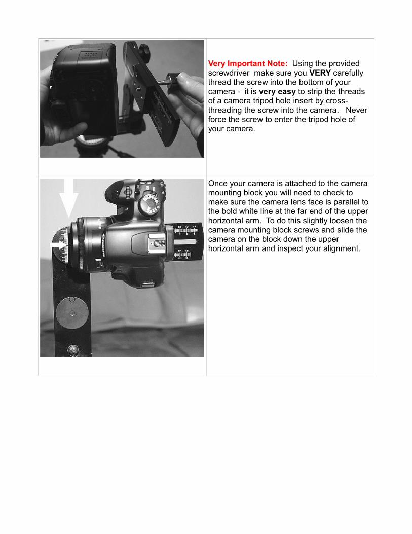
Very Important Note: Using the provided screwdriver make sure you VERY carefully thread the screw into the bottom of your camera - it is very easy to strip the threads of a camera tripod hole insert by cross-threading the screw into the camera. Never force the screw to enter the tripod hole of your camera.
Once your camera is attached to the camera mounting block you will need to check to make sure the camera lens face is parallel to the bold white line at the far end of the upper horizontal arm. To do this slightly loosen the camera mounting block screws and slide the camera on the block down the upper horizontal arm and inspect your alignment.

NOTE: Most DSLR cameras have an LCD screen on the back of the camera that is parallel to the face of the lens. You can probably properly align your camera on the camera mounting block each time by checking to make sure your LCD screen is parallel with the back of the camera mounting block.
You are now ready to use your Panosaurus.
To learn how to calibrate your lenses proceed to Step 5.
Step 5Finding the optical centers of your lenses
Please read carefully to avoid making common mistakes.There are several methods you can use to find the optical center of lenses.
The picture to the left shows one setup to find the optical center of lenses with focal lengths of less than 70mm.
Place the little nail from the parts bag on the front edge of a table or counter somewhere. Then tape a piece of paper onto a wall about 30-36 inches behind the nail. Draw a very dark straight line on the paper. (Print the last page of these instructions for a good dark line)

Next set your tripod with your Panosaurus and camera mounted directly in front of the nail so the height of your tripod has the lens level with the nail.
The front of the camera lens should be about 4-12 inches from the nail – or as close as you can possibly get to the nail and still be able to focus the camera fairly well on both the line and nail at the same time.
NOTE: Picture shows a Panosaurus Rex rather than a Panosaurus 2.0.
STEP A: Position the tripod so that when you look at the LCD screen or viewfinder this is what you see. The nail needs to be aligned with the line on the paper and in the EXTREME left hand area of the frame.
VERY IMPORTANT: This is ALWAYS the starting point of the procedure. You will probably have to move not only the rotator of the Panosaurus but also the tripod in order to get into this starting position.
Now rotate the rotator of the Panosaurus (DO NOT MOVE THE TRIPOD) until you see the nail and line in the extreme right hand of the frame. The nail and line will probably now be out of alignment - either to the right or left of the line. If the nail is to the right of the line this "probably" means the camera needs to be moved further forward on the upper horizontal arm. (This depends on the design of the lens)

The nail in this picture has moved to the left of the line when it was rotated from the left side of the frame to the right side of the frame. This means that you will probably need to move the camera back toward you on the metal arm. (This depends on the design of the lens)
Now slightly loosen the 2 screws that secure the camera mounting block to to the upper horizontal arm of the Panosaurus and slowly move the camera forward or backward on the upper arm until you see that the nail is about HALFWAY from the distance it currently is from the line - as in the picture on the left – then tighten the screws back down.
Note: If the nail had been on the right of the line to begin with then move halfway in other direction closer to the line.
Now rotate the rotator of the Panosaurus back so the nail and line are in the left side of the frame.
Now the nail and line should now be out of alignment on the left side of the frame by the same amount that it is out of alignment on the right side of the frame and you may have come close to finding the optical center point.

Ultimately you are striving to achieve the results seen in the picture on the left. The nail is aligned in the left of the frame and as you pan the camera with the rotator to the right of the frame the nail remains aligned with the line.
In order to ensure that you have achieved this goal you now return to STEP A and precede to this point again and again until the goal is achieved.
To ensure that you are perfectly calibrated you may want to take a picture of the left frame area and then pan to the right frame area and take another picture. Load the two pictures into your image editing software and greatly enlarge them. (If your camera allows you to enlarge in your LCD playback screen this is a good method also) If the two pictures are very similar (as are the two pictures on the left) then you have reached the optical center. Otherwise you will need to keep fine tuning the position of the camera on the upper arm. Once you are satisfied that you have reached the optical center be sure to note where on the metal Arm the Camera Mounting Block rests. This will be the position you always place the camera on the metal arm when you shoot at that particular focal length.
The back of the camera mounting block is used to point to the ruled lines on the upper horizontal arm. The top set of numbers represents the distance from the tripod hole of a DSLR camera to the point of rotation on the rotator. (The optical center of the lens) The bottom numbers of the top set of lines represents the distance from the tripod hole of an offset tripod hole camera to the point of rotation on the rotator.Note: Picture shows older version upper arm.

If the camera mounting block has been pushed as far back as possible on the upper horizontal arm then the front of the camera mounting block points to the ruled lines to show the distance from the tripod hole of a DSLR camera to the point of rotation on the rotator arm or the optical center of the lens.
Note: Picture shows older version upper arm.
Finding the optical center for longer focal length lenses.To find the optical center of a lens with a focal length of over 70mm you will probably need to set up your camera outdoors.
The picture on the left shows how I have set my camera to align with a pole and the edge of a window in the left of my frame. The pole is about 5 feet from my camera and the window is about 50 feet from the camera. The focal length of my lens is 100mm.
The picture on the left shows what my alignment looks like when I then pan the camera to put the pole in the right side of the frame.
I will follow the same procedure as with the nail and the line on paper to perfectly align the pole and the edge of the window in both sides of the frame.
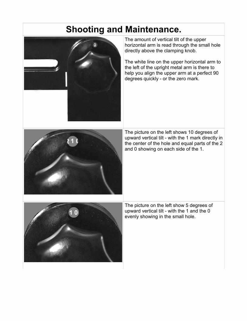
Shooting and Maintenance.The amount of vertical tilt of the upper horizontal arm is read through the small hole directly above the clamping knob.
The white line on the upper horizontal arm to the left of the upright metal arm is there to help you align the upper arm at a perfect 90 degrees quickly - or the zero mark.
The picture on the left shows 10 degrees of upward vertical tilt - with the 1 mark directly in the center of the hole and equal parts of the 2 and 0 showing on each side of the 1.
The picture on the left show 5 degrees of upward vertical tilt - with the 1 and the 0 evenly showing in the small hole.

The rotator arm points to the degrees of rotation on the degree marking platform. The platform is color coded to enable shooting of 30, 40 , 60 or 90 sequence shots to be made easily without having to remember or count numbers.
The tension of the rotator arm is controlled by the screw running through the rotator arm into the platform. You can adjust this tension with a screwdriver. Be very careful. It only takes the smallest of turning to greatly effect the tension.
Important note: Never unscrew the rotator screw all the way as this could ruin the tension device inside the base.The Panosaurus is designed to give long years of service without any maintenance.
You may want to visit the Max Lyons website and image gallery for inspiration and to learn more about the art of panoramic photography.
Happy shooting.

Print this page to use as a line to tape to wall for lens calibration.