Embed Size (px)
Citation preview

User's Guide
ServiceRanger™ 4TCMT0072 EN-USDecember 2015
Table of Contents
Welcome! 1
Introduction to ServiceRanger 2
Getting Started 3
System Requirements 3
Activation 4
License Validation 5
Subscription and Renewals 5
Vehicle Communication Adapters 6
Eaton Products 7
Getting Started with ServiceRanger 8
Starting ServiceRanger 8
Connecting to the Vehicle 8
Connections 10
The Connection Process 10
Status Bar Messages 17
Lost Connection 18
Tour of the Workspace 19
Workspace 19
Navigation Menu 20
Go To Menu 20
Connect/Disconnect Button 21
Service Activity Report Button 21
Help Menu 21
The Main Content Area 22
Secondary Navigation 22
Toolbars 22
About the Status Bar 25
Features 26
Using ServiceRanger Overview 26
Main Functions 26
Home 26
Vehicle fault codes 28
Fault Codes Overview 28
Clearing Fault Codes 30
Copying Fault Codes 31
Viewing Troubleshooting Information 31
Vehicle data monitor 34
Data Monitor Overview 34
Viewing Parameters 34
Parameters Files 36
Data Monitor List 38
Pausing Display 38

Components Tab 39
Calibrations and configurations 41
Calibration and Configuration Overview 41
Changing a Product Configuration 43
Templates 44
Changing a Product Calibration 46
Programming 48
Programming Overview 48
Updating Product Software 48
Service routines 52
Service Routines Overview 52
Clutch Abuse Utility 53
Clutch Service Utility 54
Electronic Clutch Actuator (ECA) Clutch Service Utility 55
Low Capacity Inertia Brake (LCIB) Deceleration Test 59
Grease Interval Reset 59
Hybrid Output Override Test 60
Grade Sensor Calibration 62
Park Pawl (T-handle) Calibration 63
Driver Interface Type Reset Utility 65
Diagnostic Test 65
Clutch Cooling 66
Clutch Disable Valve Test 67
Clutch Pressure Calibration 69
Clutch Touch Point Calibration 70
Grade Sensor Calibration 71
Line Pressure Calibration 72
Line Pressure Test 73
Shift Device Calibration 75
Rail Calibration 76
Product information 78
Product Information Overview 78
Viewing Product Information 78
Printing Product Information 79
Reports 81
Reports Overview 81
Diagnostic Reports Overview 81
Printing Diagnostic Report 82
Export and Email Diagnostic Report 83
Service Reports Overview 83
Starting a New Service Report 84
Resuming a Paused Service Report 85
Viewing a Saved Report 86
Working with a Service Report 88

Send Data to Eaton 91
Settings 92
Connection Settings 92
Update Status 93
General 94
License 95
Support 96
Update Manager 97
Check for updates 97
Support 98
Technical Support 98

Welcome!
Welcome!Eaton has become an innovator and leader in diagnostic and service tools for the commercial
vehicle market. ServiceRanger™ is the only recommended tool for servicing an unbeatable com-
bination of the best drivetrain, hybrid power and safety solutions from Eaton Corporation.
ServiceRanger is a computer-based electronic service and diagnostic program that provides access
to your Eaton electronic products. With ServiceRanger, you can increase uptime, save money, per-
form accurate repair procedures, all while increasing productivity and profits.
Some of the major benefits of using ServiceRanger:
l View information about the connected ECUs
l View active and inactive diagnostic fault codes
l View data parameters in real time
l View the current configuration of a product
l Change product configurations
l Program (reflash) product software
l Print reports and diagnostic results
1

Introduction to ServiceRanger
Introduction to ServiceRangerServiceRanger is a computer software program developed by Eaton to diagnose and service com-
mercial vehicle components manufactured by Eaton. ServiceRanger is designed to communicate
with vehicle component controllers via the vehicles diagnostic link connection. ServiceRanger
complies with the SAE surface vehicle recommended practices for J1587 and J1939 vehicle com-
munications, as well as the TMC RP1210-B communications standard developed for vehicle link
adapter communications.
The following products are supported:
l Eaton AutoShift/UltraShift™ Gen2 Transmissions
l Eaton Lightning Transmissions
l Eaton AutoShift/UltraShift™ Gen3 Transmissions
l Eaton UltraShift PLUS Transmissions
l Eaton Hybrid Electric Systems
l Eaton Hydraulic Launch Assist
l Fuller Advantage™ Series
Important: The license you purchased determines what products are supported by
your copy of ServiceRanger. Please consult your invoice or order information for
more information.
Notes:
l Eaton AutoShift Gen1 and Bendix VORAD EVT-300 are not supported by ServiceRanger 4.
ServiceRanger 2 is required for servicing these products.
l Bendix VORAD VS-400 system is no longer supported by ServiceRanger. Contact your Ben-
dix representative for more information.
2

Getting Started
Getting Started
System Requirements
To successfully install and operate ServiceRanger, your computer must meet the following system
requirements:
l Platform: IBM or 100% Compatible
l Operating System (32 and 64-bit versions):
l Microsoft Windows® XP with Service Pack 3
l Microsoft Windows® Vista®
l Microsoft Windows® 7
l Microsoft Windows® 8.x
l Processor: 1.8 GHz or greater, dual core or greater
l RAM Memory: 2 GB or greater
l Hard Drive: 40 GB or greater
l Display: SVGA (1024 x 768 pixels) Color
l Internet: Broadband Internet connection required for license validation and updates
l Required Software: Microsoft .Net Framework 4.0
In addition, the computer must meet the system requirements for your communication adapter.
For more information about the communication adapter hardware requirements, please contact
the communication adapter manufacturer.
Note:
l When installing ServiceRanger, you must have administrator user permissions to install and
activate the software on your computer. If you are unsure about your user permissions, con-
sult with your organization's computer support personnel before installing this software.
Microsoft andWindows are either registered trademarks or trademarks of Microsoft Corporation in
the United States and/or other countries.
3

Getting Started
Activation
When you purchase a software product from Eaton, you are issued a serial number that rep-
resents your license to use that software. You must activate your software product to confirm that
each copy of the product is not installed on more than the limited number of computers that is indi-
cated in the software end user license agreement (EULA).
Activation is intended to protect your rights as a consumer to use the license to its full extent, and
it is also intended to protect Eaton’s rights as a software developer. Only a genuine software
license entitles you to critical updates and technical support. You may not be able to use certain
versions of this software if it is not activated.
An Internet connection and registration are required for software activation and
activation must be completed prior to use of the software product.
When the installation is complete and you start the ServiceRanger program for the first time, the
software is locked. To unlock the software you must first enter your serial number you obtained
during the product purchase and perform the activation process.
The information you enter is used tomake it easier for you tomanage your licenses on the cus-
tomer portal where you purchased your license. The following fields are required for the activation
process to be successful:
l Name
l Organization
4

Getting Started
l Serial Number
l Order number
l Computer name
Failure to properly register and activate this software, or any unapproved dis-
tribution or use of this software is strictly prohibited by Eaton Corporation and may
be considered a violation of the Software License Agreement.
License Validation
With an active ServiceRanger 4 license, you PCmust connect to the Internet at least once every
45 days to re-validate the license.
As the 45 day validation end date approaches, an informational message will be displayed starting
at 10 days and then each day until the required validation is performed. If the validation period has
passed, ServiceRanger 4 will cease to function and you will be required to connect to the Internet
to re-validate the license.
If your PC is connected to the Internet, the license validation will occur automatically and no user
interaction is needed. ServiceRanger 4 does not need to be running for the validation process to
occur.
Subscription and Renewals
Your license is valid for a period of time based on the package you purchased -most often a 1 year
period. This subscription period begins on the day you purchased your license. During the sub-
scription period, you are entitled to any updates and new features that are part of your purchased
package free of charge.
You must renew your license within the renewal period, which begins 90 days prior to the expi-
ration date. In addition, there is a 30 day grace period after the expiration in which you can renew
your existing license. After this period, you will be required to purchase a new license at full cost.
To renew your subscription, return to your user account and review your current licenses. Once
you have purchased your renewal, ServiceRanger will automatically update the expiration date the
next time it connects to the Internet. Your license and subscription information can be viewed in
ServiceRanger's settings screen. See "Settings" on page 92
5
Getting Started
Vehicle Communication Adapters
ServiceRanger complies with the SAE Surface Vehicle Recommended Practices for J1587 and
J1939 vehicle communications, as well as the communication standards as defined by the Truck
Maintenance Council (TMC) recommended practice RP1210-B for vehicle link adapter com-
munications.
ServiceRanger requires the use of a vehicle adapter that is RP1210B compliant and has device driv-
ers that are compatible with the computers operating system and external communications ports
(ie: USB, Serial, etc.). Contact your communication adapter manufacturer for information on
driver installation, as well as operating system and ServiceRanger compatibility questions.
Eaton periodically posts information about known communication adapter compatibility issues
with ServiceRanger on Roadranger.com.
6

Getting Started
Eaton Products
ServiceRanger has features that support diagnosing the entire vehicle, but it also has additional
features especially for Eaton products. It is important that you understand the difference between
an Eaton product and other products installed in the vehicle.
An Eaton product is a product manufactured and sold by Eaton and is designed to work with Serv-
iceRanger (e.g. AutoShift/UltraShift transmission). These products contain special, or proprietary,
protocols that allow extra features above and beyond the normal SAE protocols. Examples of these
features include special product tests that allow you to turn on and off actuators, or view special
diagnostic data such as snapshot and vehicle performance analysis information.
A vehicle component, such as an engine or ABS system, that complies with either the SAE J1587
or J1939 communication link may work with some but not all ServiceRanger functions. Examples
include diagnostic fault codes and components data monitor parameters such as road or engine
speed.
7

Getting Started
Getting Started with ServiceRanger
Before connecting to the vehicle with ServiceRanger make sure the vehicle communication
adapter is properly connected to the vehicles diagnostic connector and to the computers com-
munication port (e.g. USB, Comm1, etc). Verify the communications adapter is powered. If the
adapter does not have a power indicator lamp it may be necessary to use a volt meter to verify the
adapter is getting power from the vehicles diagnostic connector. Finally, turn the vehicles ignition
key to the on position. Refer to OEM service information for troubleshooting power issues.
Starting ServiceRanger
Once the communications adapter is properly connected to the vehicle and the computer, start
ServiceRanger by double-clicking the ServiceRanger shortcut icon located on the computers desk-
top screen. You can also start ServiceRanger from the shortcut located in the "Eaton | Serv-
iceRanger 4" folder in the Windows Start programsmenu.
Working Offline
When ServiceRanger has successfully started the main home screen appears. This screen contains
quick reference information including links to recent service reports, update information, and serv-
ice literature. When not connected to the vehicle (offline mode), the following features maybe
available, depending on your version of ServiceRanger.
l Service Reports - Keep track of service activity automatically and improve communication
between you and your customer andwith Eaton customer support agents. See "Service
Reports Overview" on page 83
l Product Information - Find the information you need to quickly troubleshoot, remove and
install components on your Eaton products.See "Product Information Overview" on page 78
l Settings - Edit your preference settings for ServiceRanger. See "Settings" on page 92
Connecting to the Vehicle
Near the top of the screen is information related to the currently configured vehicle com-
munication adapter and an option to connect to the vehicle. Selecting the Connect button auto-
matically starts vehicle communications and begins the product detection process.
8

Getting Started
9

Getting Started
Connections
The connection process is an important first step when using ServiceRanger. The process includes
several steps, which are detailed below, that are automatically performed by ServiceRanger. A fail-
ure at any point is displayed for quick troubleshooting.
The Connection Process
When you select Connect, you will be presentedwith the following dialog:
At this time, ServiceRanger is attempting tomake a connection to:
1. Communication adapter driver on your computer.
2. Then to the communication adapter hardware,
3. Then to vehicle communication messages,
4. Finally, detection of Eaton products.
Depending on the information received, you will be presentedwith many different options, each
one described below:
10

Getting Started
Successful Eaton Product Detection
If all steps were successful, then you will be presentedwith the Product Detection dialog. Depend-
ing on your vehicle configuration, each Eaton product detected is displayed.
Select the Eaton product you want to work with, and select Ok to return to the previous screen. To
view fault codes, select Go to Fault Codes.
Note: You can only work on one Eaton product at a time. If you have multiple Eaton products on
the vehicle, you must change the active Eaton product by using the Product Connection dialog.
See "Eaton Product Connection Status" on page 17
11

Getting Started
Connection Issues
The failed to connect messages are displayedwhen you have started the connection process but
ServiceRanger was unable to make a connection to the communication adapter, the vehicle, or an
Eaton product. Depending on the communication adapter capabilities, several different error mes-
sages could be displayed and are detailed below.
Connection Failed - Communication Adapter
When this message is displayed, the issue is most likely to be between your computer and the com-
munication adapter.
Notes:
l Check the cable connections (e.g.USB cable unplugged).
l Make sure the communication adapter is powered.
l Make sure the correct driver is configured for the adapter you are using.
12

Getting Started
Connection Failed - No Vehicle Data
When this message is displayed, the issue is most likely between your communication adapter and
the vehicle. ServiceRanger was able to make a connection to the communication adapter; how-
ever, there were no vehicle messages.
Notes:
l Check tomake sure the ignition key is in the ON position.
l Check the vehicle communication data link wiring.
13

Getting Started
Connection Failed - Communication Adapter Driver
This message indicates ServiceRanger was not able to locate a properly installed RP1210 com-
munication adapter driver.
Notes:
l Reinstall the communication adapter driver that was provided by the manufacturer.
l Make sure ServiceRanger is configured properly for the communication adapter you are
using. See "Connection Settings" on page 92
14

Getting Started
No Eaton Product Detected
This message indicates ServiceRanger successfully connected to the vehicle andwas able to read
data link messages; however, it did not detect an Eaton product.
Notes:
l Power and ground issue to the Eaton product.
l Vehicle data link wiring between the Eaton product and diagnostics connector.
l Inoperable Eaton product ECU.
l No Eaton product installed in the vehicle.
15

Getting Started
Unlicensed Product
This message indicates the vehicle is equippedwith an Eaton product that is not supported by this
version of ServiceRanger. You will need to upgrade to the correct version of ServiceRanger that sup-
ports this product.
Notes:
l Selecting Ok will disconnect ServiceRanger from the vehicle.
16

Getting Started
Status Bar Messages
In addition to the main connection dialog, the status bar contains useful information regarding the
connection status. The status bar has two important indicators, the vehicle link status and
detected Eaton products.
Vehicle Link Status
Disconnected
The disconnectedmessage is displayedwhen you either first start ServiceRanger and have not yet
connected OR you have disconnectedmanually from the vehicle by selectingDisconnect on the
navigation menu.
Connected
The connectedmessage is displayedwhen ServiceRanger has made a successful connection to the
vehicle on at least one communication link (J1587 or J1939).
Note:
l You can see a detailed connection message by selecting the connection icon with your
mouse pointer.
Eaton Product Connection Status
The product connection status is displayed on the lower left corner of the status bar and indicates
the product andmodel that is currently selected. In addition to displaying the current product, you
can select the product description to view more information and change the current selected prod-
uct.
17

Getting Started
Lost Connection
The lost connection message is displayedwhen a valid connection was established to the vehicle
and then lost. The most likely cause lies between the communication adapter and vehicle.
Note:
l ServiceRanger automatically retries to establish the connection to the vehicle.
18

Tour of the Workspace
Tour of the Workspace
Workspace
ServiceRanger's workspace is a flexible, modern user interface and gives you several options allow-
ing you to work the way that you want. It is important that you become familiar with the appli-
cation. The more you learn about its potential, the better you can take advantage of its features,
tools, and options.
The user interface consists of the following three major sections:
l Navigation Menu - Located on the top of the interface, it allows you access to the main
functions of the software. Examples include fault code viewing, data monitor and changing
configuration settings just to name a few.
l Content Area - This area displays the content associated with each shortcut on the navi-
gation menu. This is the main work area where you will be accomplishing your tasks. For
example, this is the area where fault codes or product software are displayed.
l Status Bar - At the very bottom of the interface is a status bar. The most notable use for
the status bar is to see the vehicle connection status.
19

Tour of the Workspace
Navigation Menu
The ServiceRanger user interface includes a navigation menu at the top of the application window
containing several menu options. Many menu items are similar to what you might find in other
diagnostic service tools, such as fault codes and data monitor.
Go To Menu
The Go To button opens the main navigation menu. It has several shortcuts, or links, to the var-
ious features of ServiceRanger.
Home Overview information - See "Home" on page 26
Fault CodesView active and inactive diagnostic codes - See "Fault Codes Over-
view" on page 28
Data MonitorView real time vehicle data parameter values - See "Data Monitor
Overview" on page 34
ConfigurationsView and edit vehicle configuration parameters - See "Con-
figuration" on page 1
ProgrammingReflash product software - See "Programming Overview" on page
48
Service RoutinesPerform advanced product tests - See "Service Routines Overview"
on page 52
Product InformationView service information for Eaton products - See "Product Infor-
mation Overview" on page 78
20
Tour of the Workspace
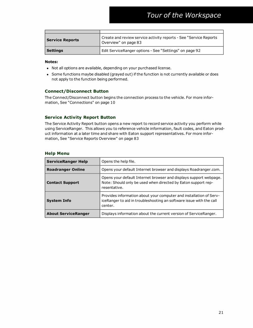
Service ReportsCreate and review service activity reports - See "Service Reports
Overview" on page 83
Settings Edit ServiceRanger options - See "Settings" on page 92
Notes:
l Not all options are available, depending on your purchased license.
l Some functions maybe disabled (grayed out) if the function is not currently available or does
not apply to the function being performed.
Connect/Disconnect Button
The Connect/Disconnect button begins the connection process to the vehicle. For more infor-
mation, See "Connections" on page 10
Service Activity Report Button
The Service Activity Report button opens a new report to record service activity you perform while
using ServiceRanger. This allows you to reference vehicle information, fault codes, and Eaton prod-
uct information at a later time and share with Eaton support representatives. For more infor-
mation, See "Service Reports Overview" on page 83
Help Menu
ServiceRanger Help Opens the help file.
Roadranger Online Opens your default Internet browser and displays Roadranger.com.
Contact Support
Opens your default Internet browser and displays support webpage.
Note: Should only be used when directed by Eaton support rep-
resentative.
System Info
Provides information about your computer and installation of Serv-
iceRanger to aid in troubleshooting an software issue with the call
center.
About ServiceRanger Displays information about the current version of ServiceRanger.
21
Tour of the Workspace
The Main Content Area
The ServiceRanger user interface includes a main content area. This is where information is dis-
played, andwhere most of your interactions with the program will occur. For example, in the Fault
Code feature, ServiceRanger displays Eaton product and vehicle fault code information alongwith
various functions, such as clearing and printing, that you can perform. Many items are similar to
what you might find in other diagnostic service tools.
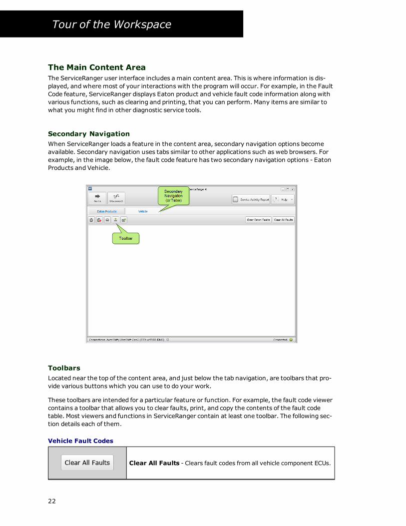
Secondary Navigation
When ServiceRanger loads a feature in the content area, secondary navigation options become
available. Secondary navigation uses tabs similar to other applications such as web browsers. For
example, in the image below, the fault code feature has two secondary navigation options - Eaton
Products and Vehicle.
Toolbars
Located near the top of the content area, and just below the tab navigation, are toolbars that pro-
vide various buttons which you can use to do your work.
These toolbars are intended for a particular feature or function. For example, the fault code viewer
contains a toolbar that allows you to clear faults, print, and copy the contents of the fault code
table. Most viewers and functions in ServiceRanger contain at least one toolbar. The following sec-
tion details each of them.
Vehicle Fault Codes
Clear All Faults - Clears fault codes from all vehicle component ECUs.
22

Tour of the Workspace
Clear Eaton Faults - Clears fault codes from the connected Eaton
product ECUs.
Copy - Copies the selected fault code and sends it to the computers
clipboard.
Copy All - Copies the contents of the fault code table and sends it to
the computers clipboard.
Print Preview - Creates a diagnostic report and opens the report pre-
viewwindow.
Export - Creates a diagnostic report and saves it to your computers
hard drive as a pdf file.
Email - Creates a diagnostic report and opens and attaches the report
to the default email client.
Vehicle Data Monitor
Pause - Freezes the data being displayed from the vehicle.
Play - Restarts, or unfreezes, the display to be updated with data.
Open - Displays a dialog of available parameter files.
Save - Saves the currently selected list of data monitor parameters to a
file on your computers hard drive.
Clear List - Removes all selected parameters from the current view.
23

Tour of the Workspace
Product Configurations
Open - Displays a dialog of available configuration templates.
Save - Saves the current list of configuration settings as a template on
your computer.
Clear Pending - Clears any pending changes from the new value col-
umn.
Export - Creates a diagnostic report and saves it to your computers
hard drive as a pdf file.
Print Preview - Creates a diagnostic report and opens the report pre-
viewwindow.
Email - Creates a diagnostic report and opens and attaches the report
to the default email client
Service Activity Report
Print Preview - Creates a diagnostic report and opens the report pre-
viewwindow.
Email - Creates a diagnostic report and opens and attaches the report
to the default email client.
Export - Creates a diagnostic report and saves it to your computers
hard drive as a pdf file.
Delete - Removes the service activity report from your computer.
Notes:
l Not all options are available, depending on your purchased license.
l Some functions may be disabled (grayed out) if it is not currently available or does not apply
to the action being performed.
24

Tour of the Workspace
About the Status Bar
The status bar is located at the bottom of every document window and displays useful infor-
mation—such as the current connection status and brief instructions. The most notable infor-
mation is the current connection status between ServiceRanger and the vehicle. For more
information, See "Connections" on page 10
25
Features
Features
Using ServiceRanger Overview
Main Functions
The following information provides an overview of each major feature of ServiceRanger:
Fault Codes
The Fault Code function displays all active and inactive SAE fault messages being broadcast by all
Eaton products on the vehicle data links, alongwith their Eaton product fault codes.
Data Monitor
The Data Monitor function allows you tomonitor parameter values from different vehicle com-
ponent ECUs.
Configurations
The Configuration function allows you to view and change the current configuration of the
detected Eaton products on the vehicle.
Programming
The Programming function allows you to update, or reflash, the products ECU application software.
Service Routines
Service Routines are functions that apply to a specific Eaton product family. Some functions
include utilities to extract data files or to perform functional tests.
Product Information
The Product Information functions allows you to look up service information, such as product serv-
ice manuals and troubleshooting guides for Eaton products. In addition, the troubleshooting guide
is linked directly to the fault code information screen allowing quick and easy access to information
to perform quick repairs.
Service Reports
The Service Report features allows you to record service activities performed on a vehicle for future
reference.
Home
When ServiceRanger first opens, you see the Home screen. The Home screen is a handy window
consisting of four sections which contain high-level information.
26

Features
l Connection - The Connection section displays information about the currently configured
communication adapter and the status of the connection.
l Service Reports - Service Reports allows you to view the most recent reports you may
have created. It also allows you to perform a quick search based on VIN or Repair Order.
l Product Information - Product information allows you to view the most recent service
manuals you may have viewed. It also allows you to perform a quick search
l ServiceRanger Updates - This area displays information regarding the last time Serv-
iceRanger checked for an update and if an update was found.
27

Features
Vehicle fault codes
Fault Codes Overview
The Fault Code function in ServiceRanger displays all active and inactive SAE fault messages being
broadcast by all component ECUs on the vehicle data links. The function is split into two separate
sections - Eaton Product fault codes and Vehicle fault codes. Each type of fault codes is described
below.
Eaton Product Fault Codes
Eaton product fault codes are displayed for each Eaton product detected in the vehicle. The fault
codes are separated into groups and listed by Eaton products names.
The following information is displayed:
l Product Description - The Eaton Product name, each fault code is displayed below this infor-
mation.
l Code - The Eaton fault code assigned to the ECU broadcasted fault message. ServiceRanger
only displays fault codes for supported Eaton products. This field is blank for unsupported
components or unrecognized fault messages.
l Status - Status of the fault (Active or Inactive).
l ID - Fault Identifier (J1587 PID\SID or J1939 SPN).
l Description - Eaton description of the fault.
l FMI - Failure Mode Identifier and description of the failure mode.
l Count - The number of times the product has detected the transition of a fault from active to
inactive and back to active status.
l Timestamp - The time, in runtime of the product (e.g. key on time) since the fault code was
detected. Example: 0h 32m - indicates the last active fault code status was 32 minutes of
runtime ago.
l Link - The vehicle data link on which the fault message is being broadcast (J1587 or J1939).
28

Features
Notes:
l If no fault codes are detected, ServiceRanger displays "No Faults."
l Selecting each fault code opens a secondary information view below the fault code, including
a link to the troubleshooting guide. See "Viewing Troubleshooting Information" on page 31
Vehicle Fault Codes
Vehicle fault codes displays fault information for all vehicle ECUs communicating to ServiceRanger.
The following information is displayed:
l Component Description - The SAE description and communication link of the component,
each fault code is displayed below this information
l Status - Status of the fault (Active or Inactive)
l ID - Fault Identifier (J1587 PID\SID or J1939 SPN)
l Description - SAE description of the fault
l FMI - Failure Mode Identifier and description of the failure mode
l Count - The number of times the product has detected the fault condition transition from
active to inactive and back to active status
29

Features
Note:
l If no fault codes are detected, ServiceRanger displays "No Faults."
Clearing Fault Codes
This command clears (erases) fault codes from the currently connected components, or ECUs.
Clearing all vehicle fault codes:
1. View fault codes.
2. Select Clear All Faults button from the Fault Code toolbar.
3. Select Ok to confirm.
4. All fault codes are cleared.
Notes:l This option may not be displayed for all products andmodel years depending on the level of
OBD compliance.
l This command clears all fault codes from all vehicle ECUs.
l Active fault codes may reappear if the ECU detects the fault condition again.
l Not all vehicle component manufactures support the SAE clear fault command.
Clearing Eaton fault codes:
1. View fault codes.
2. Select Clear Eaton Faults button from the Fault Code toolbar.
3. Select Ok to confirm.
4. All fault codes from Eaton products are cleared.
30

Features
Notes:
l This command clears fault codes from only Eaton products. It does not clear fault infor-
mation from other vehicle ECUs.
l Active fault codes may reappear if the ECU detects the fault condition again.
Copying Fault Codes
You can copy the contents of the fault code display to the computers clipboard. This allows you to
easily transfer the information to other software applications such as a shopmaintenance system,
word processor, or spreadsheet.
Copying a selected fault code:
1. View fault codes.
2. Select a fault code displayed in the table.
3. Select Copy icon from the Fault Code toolbar.
4. The selected fault code is copied to the computers clipboard.
Notes:
l The contents are copied as a tab-separated list.
Copying all fault codes:
1. View fault codes.
2. Select Copy All icon from the Fault Code toolbar.
3. All fault codes are copied to the computers clipboard.
Notes:
l The contents are copied as a tab-separated list.
Viewing Troubleshooting Information
You can quickly view troubleshooting information for Eaton fault codes within ServiceRanger.
31

Features
Viewing product troubleshooting information:
1. View Eaton fault codes.
2. Select a fault code displayed in the table to view detailed information.
3. Select Troubleshoot.
4. The fault code troubleshooting information is displayed.
Notes:
l If ServiceRanger can not determine what troubleshooting book to open automatically, it
asks you for input as to what information to display.
Working with the product information window
When you open the product information window from the fault code screen, it is displayed in a win-
dow floating above ServiceRanger. This allows you tominimize the window and continue to use
ServiceRanger. The window is available near the bottom of the screen allowing you quick access to
the information you were viewing.
32

Features
Minimizing the window:
1. Select Troubleshoot from the fault code screen.
2. Select theminimize button.
3. The window is displayed along the bottom of ServiceRanger near the status bar.
Note:
l You can maximize the window at anytime while using ServiceRanger.
33

Features
Vehicle data monitor
Data Monitor Overview
The Data Monitor function allows you tomonitor parameter values from different vehicle com-
ponent ECU's. Examples of parameters are input shaft speed, engine throttle position, and road
speed.
Viewing Parameters
The selection of parameters to be added to the list view is easily accomplished in ServiceRanger.
Each parameter is included in the selection menu and is located in a group, or category. Examples
of a category would be Speed or Position. The speed category would contain parameters such a
road speed, engine speed, or output shaft speed. The parameter viewing list is shared across the dif-
ferent views such as the chart and list.
34

Features
Selecting a parameter:
1. Select Data Monitor from the navigation menu.
2. From the parameter selection menu, select a Category.
3. The available parameters in that category is displayed.
4. Select the Source for the parameter.
5. The parameter appears selected and is added to the viewing list.
Notes:
l The selection menu can be filtered by All parameters, Eaton only parameters, or selected
parameters.
l You can search for parameters by using the search feature at the top of the selection menu.
l If a parameter is not available from the vehicle, it appears faded, or grayed out.
l If a component is unable to determine the value of a parameter, ServiceRanger displays the
parameter value as "error."
Removing a parameter from the view:
1. Select Data Monitor from the navigation menu.
2. From the parameter selection menu, select a Category.
3. The available parameters in that category are displayed.
4. De-select, or un-check, the Source for the parameter.
5. The parameter is removed from the viewing list.
35

Features
Notes:
l Optionally, you can filter the list and only display the currently selected parameters to
quickly remove a parameter from the view.
l Up to thirty (30) parameters can be viewed at one time.
Parameters Files
Data Monitor parameter files allow you to save a set of parameters for use at a later time. This is
useful if you find yourself looking at the same set of parameters on several vehicles. In addition to
creating your own parameters files, each Eaton product has a pre-defined parameter file asso-
ciated with it.
Saving a parameter file:
36

Features
1. Select Data Monitor from the navigation menu.
2. Select parameters from the parameter selection menu.
3. Select Save icon from the toolbar.
4. Enter a name for the parameter file and select Save.
5. The parameter file is saved.
Notes:
l Up to thirty (30) parameters can be viewed at one time.
Opening a parameter file from the menu:
1. Select Data Monitor from the navigation menu.
2. Select Open icon from the toolbar.
3. Select the parameter file in the list and select Open.
4. The parameter file opens and displays in the view.
Notes:
l Up to thirty (30) parameters can be viewed at one time.
l The parameters in the file replace the selected parameters currently being viewed.
Deleting a parameter file:
1. Select Data Monitor. from the navigation menu.
2. Select Open icon form the toolbar.
3. Select the parameter file in the list and select Delete.
4. The parameter file is deleted.
Notes:
l The file is permanently deleted and can not be undone.
37

Features
Data Monitor List
The list view allows you to see parameters in a data grid. This allows you to quickly see and com-
pare many parameters at one time.
The following information is displayed:
l Link - The data link the parameter message is being broadcast (J1587 or J1939).
l Source - The source, or vehicle component ECU, sending the data.
l Parameter - Parameter ID value (PID, SID, or SPN).
l Description - SAE or Eaton description of the parameter.
l Value - Value of the parameter.
l Units - Units that the parameter is being displayed.
l Max\Min - The maximum andminimum parameter value recorded.
Notes:
l If a parameter is selected but not available from the vehicle, it appears faded, or grayed
out.
Removing all parameter from the view:
1. Select Data Monitor from the navigation menu.
2. Select Clear Parameter list icon from the toolbar
3. The parameter is removed from the viewing list.
Pausing Display
38

Features
The display can be paused allowing you to evaluate data parameters that maybe updating rapidly.
Pausing the display:
1. Select Data Monitor from the navigation menu.
2. Select Pause icon from the data monitor toolbar.
3. The data monitor parameters stop updating their values.
Notes:
l After pausing the display, you can re-enable the display by selecting the pause icon again.
Components Tab
The Vehicle Components function is used to view basic information about each component on the
vehicle that is detected by ServiceRanger. This function can be used to determine if all vehicle com-
ponents are powered up and on which data links each component is communicating.
The following information is displayed:
l Link - the data link the component is communicating on (J1587 or J1939). Most vehicle com-
ponents are detected on both data links.
l Source Address - Source address of the component (J1587 MID or J1939 Source Address).
l Component Description - SAE Component Description of the component's source address.
l Make, Model, Serial Number, and Software Version - This is the component identification
information provided by the component ECU manufacturer. Not all component man-
ufacturers support broadcasting component identification information. If one or more of
these fields are blank, then the component does not support it.
39

Features
Notes:
l A component is grayed out if it does not communicate with ServiceRanger every ten sec-
onds.
l Some components broadcast on multiple links and as a result, ServiceRanger displays those
components twice.
40

Features
Calibrations and configurations
Calibration and Configuration Overview
The configuration and calibration function allows you to view and change settings of the connected
Eaton products in the vehicle. Configurations allow you to tailor the vehicle to the driver's pref-
erences. Options line default start gear or PTO options are examples of configurations. Product cal-
ibrations are similar to configurations, however calibrations can change the behavior of the control
and diagnostic functions of a system without updating the software. This allows a product to be
adapted to the specific OEM chassis and engine make andmodels.
Caution: Take care changing any configurations or updating software as all Eaton
products are configured by the vehicle OEM for optimal performance.
Configurations
The main screen in Configurations is split into two sections, configuration groups and available
product configurations.
Configuration groups
Configuration groups are displayed along the side of the application. Groups allow similar or related
configurations to be displayed together. For example, all PTO configuration options are grouped
under a category called 'PTO'.
Note:
l Each Eaton product has its own set of configuration groups.
Product configuration
The Product Configuration section displays specific information about the product ECU con-
figuration settings. The Current Setting column displays how the ECU is currently configured and
the New Setting column provides optional configuration selections that may be available for the
product.
Note:
l Not all configurations can be changed, a lock icon will be displayed indicating they are read
only.
41

Features
Calibrations
The main screen in Calibrations is split into four sections, current settings, available updates,
vehicle information, and available product calibrations.
Note:
l Each Eaton product has its own set of calibrations.
l Not all Eaton products support calibrations. You may not see the calibrations tab if the con-
nected product does not support calibrations.
Calibration types
Available product calibrations are displayed along the side of the application. Each Eaton product
has different calibrations available and the display may be different than the image below.
Available updates
Available updates for the selected calibration type will be displayed near the top of the calibration
screen. If there are no updates for the current calibration, then a "Your product is up-to-date" mes-
sage will be displayed.
Note:
l You can show older revisions of the same calibration by selecting 'Show older revisions'.
l Only calibrations that are compatible with the current software will be shown.
Vehicle information
ServiceRanger filters the list available calibrations to only show you the calibrations for your
vehicle. The vehicle information section displays the information from the vehicle that is being
42

Features
used for filtering.
Note:
l Filtering information varies for each Eaton product and calibration type. The information on
your screen may be different from the image below.
Other options
The other options section will display other calibrations that may be available for your vehicle.
From here you can chose calibrations that change the behavior of the transmission, for example a
performance or economy calibration.
Note:
l Not all configurations can be changed, a lock icon will be displayed indicating they are read
only.
l You can filter the available calibrations using the table column names (e.g. performance goal
and vocation)
Changing a Product Configuration
To change a configuration value, first select a configuration group to view the available con-
figuration options. Then, in the new setting column, select or enter the new configuration setting
using the selection control or drop down list provided by ServiceRanger.
If no options are displayed, then either there are no new options for that configuration or you do
not have the necessary privilege to change the configuration. When the new configuration is suc-
cessfully downloaded, ServiceRanger reads the updated configurations from the vehicle.
To change a product configuration:
1. Select Configuration from the navigation menu.
2. Select a Configuration Group.
3. Review the current settings.
43

Features
4. In theNew Value column, select a new value for the configuration(s) you are changing.
5. When all new settings are complete, select Apply.
6. A confirmation dialog is displayed.
7. Review and confirm the new configuration settings, select Apply.
8. The new configuration(s) settings are downloaded to the Eaton product.
Notes:
l You should check for updates to ServiceRanger often, as new configurations may become
available.
l Not all configurations can be changed, a lock icon will be displayed indicating they are read
only.
l Some configurations contain rules restricting the allowable settings. For example, you can
not set default start gear higher than maximum start gear. ServiceRanger displays any rule
violations.
To clear pending changes
1. Select Configuration from the navigation menu.
2. Select a Clear Pending Changes icon from the toolbar.
3. The new value column is cleared of any pending changes.
Templates
Templates allow you to save a set of configurations for a vehicle on your computer. This allows you
to quickly apply the same set of configuration settings to multiple vehicles.
To save a configuration template:
1. Select Configuration from the navigation menu.
2. Do one of the following:
l Select Save | Current Values from the toolbar.
l Select Save | Pending Values from the toolbar.
44

Features
3. The Save Configuration Template dialog is displayed.
4. Enter a name for the configuration template.
5. Select Save.
6. The new configurations template is saved to your computer.
Notes:
l Configuration templates are saved to your computer hard drive. If you have multiple com-
puters, you need to create a template for each computer separately.
l Not all configurations can be saved to a template. Examples include serial number and trans-
mission model.
l Current values will store all of the vehicle current configuration settings to the template.
l Pending values will store only the pending values you have selected in the new value col-
umn.
To load a configuration template:
1. Select Configuration from the navigation menu.
2. Select theOpen icon from the toolbar.
3. Select the template from the available list.
4. Select Load.
5. The template configuration settings are loaded into the new settings column. Review the
changes and apply them to the Eaton product.
Notes:
l Only configuration templates that match the Eaton product andmodel currently connected
to ServiceRanger are displayed as an available template.
l As software versions change over time, new configurations may be added that do not match
your configuration template. In this case, only the configurations that match between the
software versions are loaded into the new settings column.
Importing and exporting templates:
45

Features
It may be useful to share templates between computers. The import and export template feature
allows you to save a template to a file on your local computer hard drive. You can then move the
file to another computer and import the file.
To export a configuration template
1. Select Configuration from the navigation menu.
2. Select theOpen icon from the toolbar.
3. Select a template from the available list.
4. Select Export.
5. Select a folder on your computer hard drive.
6. Select Save.
7. The template file is saved to your hard drive allowing you to transfer it to another com-
puter.
Notes:
l Only configuration templates that match the Eaton product andmodel that is currently con-
nected is displayed as an available template.
l A template file can be exported directly to a portable drive.
To import a configuration template:
1. Select Configuration from the navigation menu.
2. Select theOpen icon from the toolbar.
3. Select Import.
4. Navigate to your computers folder to locate the template file.
5. Select Ok.
6. The template is imported into ServiceRanger and is available to be selected.
Notes:
l Only configuration templates that match the Eaton product andmodel that is currently con-
nected is displayed as an available template.
Changing a Product Calibration
To change a calibration, first select a calibration type to view the available options. Then either
select the update (if available) or the new calibration from the list. You can review information
about the calibration including intended engine make andmodel, vocation, performance goal or
release notes. ServiceRanger automatically determines the list of available calibrations based on
information received from the vehicle.
To change a product calibration:
1. Select Configuration from the navigation menu.
2. Select a Calibration tab.
3. Select a Calibration type from the left menu.
4. Review the current settings.
5. In theOther options area, select a new calibration.
6. When all new calibration(s) are chosen, select Apply.
7. A confirmation dialog is displayed.
46

Features
8. Review and confirm the new calibration setting(s), select Apply.
9. The new calibration(s) files are downloaded to the Eaton product.
10. Key off and let the system power down to commit the changes.
Notes:
l You should check for updates to ServiceRanger often, as new calibrations may become avail-
able.
l Not all calibrations can be changed, a lock icon will be displayed indicating they are read only.
l Some calibrations are intended only for specific engine and vehicle models. ServiceRanger
will filter calibrations based on the VIN and engine model detected during the connection
process.
To update a product calibration:
1. Select Configuration from the navigation menu.
2. Select a Calibration tab.
3. Select a Calibration type from the left menu.
4. Review the current settings, if a new version the calibration is available it will displayed
near the top of the calibration screen.
5. Select the available update.
6. When all new settings are complete, select Apply.
7. A confirmation dialog is displayed.
8. Review and confirm the new calibration(s), select Apply.
9. The new calibration(s) files are downloaded to the Eaton product.
10. Key off and let the system power down to commit the changes.
Notes:
l If a new update is not available, ServiceRanger will display "Your product is up-to-date" mes-
sage.
47

Features
Programming
Programming Overview
The Programming function allows you to update the component ECU application software over the
vehicle diagnostic data link. ServiceRanger automatically detects which data link, J1587 or J1939,
is supported by the component for re-programming.
Before programming Eaton products, the components of the product programming and their func-
tions should be understood. The product programming is comprised of two components, they are
the Application Software and Configuration software.
Application software
Application software is the main software that makes the product work. It contains the shift logic,
self diagnostic functions, and communication functions.
Configuration software
Configuration software tailors the product to the vehicle. Examples of configuration parameters
are default start gear, maximum start gear, and shift points. Available configurations differ for
each product. For more information, See "Calibration and Configuration Overview" on page 41
There is typically an application program and a configuration program for each ECU on a product.
The Eaton AutoShift Gen2 series of transmissions has two controllers, therefore the AutoShift has
two sets of software. One for the Shift Control and another for the Transmission Controller each of
which may needed to be updated.
Important: Only use a communications adapter that has been tested and rec-
ommended by Eaton before attempting to program application software. Some com-
munication adapters and all with wireless connection methods are not well suited
for application software programming and could result in permanent damage to the
ECU.
Updating Product Software
When the Product Programming function is selected, ServiceRanger displays the current software
versions (or levels) for the selected product and any updates that it determines are available.
Some Eaton products have multiple ECUs that act together as a system. As such, it is important
that each ECU is up to date and are all compatible with each other. ServiceRanger automatically
determines the software updates available for each ECU and displays them to you as package.
Downloading the Application File
Select the software update you want to program into the product by selecting the update in the
list. You can review information about the software package including the software versions.
Caution: Interrupting the ECU download process once it has begun can result in
permanent damage to the ECU.
To Update Product Software:
48

Features
1. Select Programming from the navigation menu.
2. Select a software update from the main content window.
3. Select Confirm.
4. Review the information and select Download.
49

Features
5. The update process begins, showing each step of the programming sequence.
l Depending on the product, you may be asked to cycle the ignition key. Follow the on
screen prompts to continue.
50

Features
Notes:
l If ServiceRanger detects that the component has the most current application software com-
pared to the files that are stored in the ServiceRanger product database, ServiceRanger dis-
plays that no files are available for the selected product.
l Make sure vehicle battery voltage is at normal operating levels.
l Verify ‘good’ wiring connections between the computer, communication adapter and vehicle.
l Make sure the computer has sufficient battery power, or is plugged in, for the entire duration
of the programming steps.
Show older software
While this is not recommended , there may be times reverting to an older software version may be
needed.
Showing older software:
1. Select Programming from the navigation menu.
2. The Available updates screen is displayed.
3. Select Show older software.
4. Older software packages are displayed.
51

Features
Service routines
Service Routines Overview
A Service Routine extends the functionality of ServiceRanger beyond normal everyday service pro-
cedures. Some of the routines include uploading data from a vehicle ECU, running a product test,
or recalibrating an sensor attached to the product ECU.
When connected to a vehicle, ServiceRanger displays a list of service routines available for the cur-
rently selected Eaton product. The following APFs are available by product family:
l UltraShift Gen2
l Clutch Abuse Utility (DM and ASWmodels)
l AutoShift/UltraShift Gen3
l Clutch Service Utility (DM and ASWmodels)
l Park Pawl (T-Handle) Calibration
l Driver Interface Reset Utility
l UltraShift PLUS
l Clutch Service Utility
l Low Capacity Inertia Brake Test
l Grease Interval Reset
l Grade Sensor Calibration
l Driver Interface Reset Utility
l Procision
l Product Diagnostic Test
l Clutch Cooling
l Grade Sensor Calibration
l TRS Shift Device Calibration
l Clutch Disable Valve Test
l Clutch Touch Point Calibration
l Clutch Pressure Calibration
l Rail Calibration
l Line Pressure Calibration
l Line Pressure Test
l Electric Hybrid Powertrain
l Hybrid Output Override Test
l Grade Sensor Calibration
l Park Pawl (T-Handle) Calibration
Each Service Routine consists of an introductory 'Description and Instructions' section. This sec-
tion displays important information regarding the service routine and steps to perform. This sec-
tion is followed by the product functions and any pass or fail results.
52

Features
Launching a Service Routine
1. Select Service Routines from the navigation menu.
2. List of available service routines for the connected product is displayed.
3. Review the list and select Start.
4. The service routine is opened.
Clutch Abuse Utility
The transmission ECU maintains information about the history and performance of the UltraShift
Gen2 DM and ASWmodels. This data can be viewed, downloaded, or cleared using the clutch abuse
utility. When an UltraShift clutch is replaced, clearing the clutch data is part of the clutch replace-
ment procedure.
53

Features
Available Functions:
Start Transfer
Downloads the clutch data from the transmission ECU and display it on the screen.
Save Data
Allows you to save the extracted data to a text file on your computer. The default file name is in
year-month-day time format. (example: 20091203-082059 is Dec 03, 2009 08:20:59 AM)
Clear Clutch Data
Clears the clutch data from the transmission ECU.
Calibrate Clutch
Activates the clutch calibration routine.
Note: The command should be used after a new clutch installation. Failure to calibrate a newly
installed clutch may result in some initial harsh vehicle launches until the system manually re-
calibrates itself over time.
Clutch Service Utility
The clutch service utility is used to calibrate the clutch and clear clutch information from the
vehicle performance analysis (VPA) data. This procedure is usually done when replacing the clutch
but can also be done when performing general clutch maintenance.
54

Features
Calibrate Clutch
Starts the calibration routine within the transmissions control system.
To calibrate the clutch:
1. Key on with engine off.
2. Place the shift device in Neutral.
3. Set parking brakes.
4. Select Calibrate Clutch and follow on-screen prompts.
Clear Clutch Data
Requests the clutch data to be cleared from the transmission's VPA data.
To clear clutch data:
1. Key on with engine off.
2. Place the shift device in Neutral.
3. Set parking brakes.
4. Select Clear Clutch Data and follow on-screen prompts.
Notes:
l This routine is only available for ASW andDM transmission models.
Electronic Clutch Actuator (ECA) Clutch Service Utility
55

Features
This utility is available for products that use an Electronic Clutch Actuator (ECA) to control the posi-
tion of the clutch assembly. There are four functions in this utility that can be used in various serv-
ice procedures.
Open Clutch
Use this command to open the ECA Clutch when performing the In-Vehicle Clutch Resetting Pro-
cedure.
Warning: Make sure no hands and other body parts are not inside the clutch housing while
opening or closing the clutch.
To Open the Clutch:
1. Key on with engine running.
2. Place the shift device in Neutral.
3. Set parking brakes.
4. Select Open Clutch and follow on-screen prompts.
5. After ServiceRanger confirms that the clutch is in the Open position, key off.
6. Perform In-Vehicle Clutch Resetting Procedure. See more about In-Vehicle Clutch Reset-
ting Procedure in Heavy-Duty Clutch Service Manual (CLSM0200).
Notes:
l When clutch service is complete, the ECA Clutch will close the next time the ignition is
turned on.
Service Position
56

Features
Use this command to rotate the release fork away from the release bearing, allowing removal of
the transmission from the vehicle.
Warning: Make sure no hands or other body parts are not inside the clutch housing while open-
ing or closing the clutch.
Caution: Install the 4 shipping bolts before removing the ECA clutch from the engine flywheel.
Failure to install the shipping bolts will damage the clutch.
Important:Warranty claims with damage to the clutch caused by failure to install the shipping
bolts will be denied.
To move the Clutch to Service Position:
1. Key on with engine off.
2. Place the shift device in Neutral.
3. Set parking brakes.
4. SelectMove to Service Position and follow on-screen prompts.
5. After ServiceRanger confirms that the clutch is in Service position, key off.
6. Remove transmission for required service.
Notes:
The release fork remains in the Service position until another clutch command is performed.
Request Clutch Adjustment
Use this command to signal the Electronic Clutch Actuator (ECA) to actuate the clutch and set the
new adjustment after the ECA clutch is reset, replaced, or a new Transmission Electronic Control
Unit (TECU) is installed. Fault Code 26 or 27 indicate the clutch may be out of adjustment. See
more about Fault Code 26 and 27 in Troubleshooting Guide TRTS0930.
Important: A clutch adjustment should always be performed after a clutch replacement.
Warning: Make sure no hands or other body parts are not inside the clutch housing while per-
forming clutch adjustment.
To adjust the Clutch:
1. Key on with engine running.
2. Place the shift device in Neutral.
3. Set parking brakes.
4. Select Request Clutch Adjustment and follow on-screen prompts.
5. ServiceRanger displays Success or Fail result.
6. After a successful a clutch adjustment, drive the vehicle to allow the ECA to fine tune
clutch engagement.
Clear Clutch Data
Use this command to clear the historical clutch performance data from the Vehicle Performance
Analysis (VPA) data file stored in the Transmission Electronic Control Unit (TECU).
57

Features
Important: Clear the clutch data each time the clutch is replaced to ensure the values used in
future diagnostics are associated with the new clutch.
To clear clutch data:
1. Key on with engine off.
2. Select Clear Clutch Data.
58

Features
Low Capacity Inertia Brake (LCIB) Deceleration Test
This commands the Electronic Clutch Actuator (ECA) to actuate the Low Capacity Inertia Brake
(LCIB) 5 times to verify its function. The test fails if any of the readings are below 1000 rpm/sec.
To begin the LCIB test:
1. Key on with engine running.
2. Place the shift device in Neutral.
3. Set parking brakes.
4. Select Start and follow on-screen prompts.
5. ServiceRanger displays individual test results and indicate pass or fail. If any of the readings
are below 1000 rpm/sec the test will fail.
Grease Interval Reset
This command signals the transmission ECU to reset its clutch release bearing grease interval
counter.
59

Features
To clear the grease interval counter:
1. Key on with engine off.
2. Place the shift device in Neutral.
3. Set parking brakes.
4. Select Clear Grease Internal Counter and follow on-screen prompts.
Notes:
l Optionally, this feature can be enabled or disabled via the product configuration option in
ServiceRanger.
l At the appropriate grease interval and shortly after each engine start, “GI” momentarily
appears in the gear display, alongwith an audible tone. This continues to occur at each
engine start until the clutch service has been completed and the grease interval has been
reset.
l The operator can choose to follow the Automated Lube Schedule or the published lube guide-
lines in the Lubrication Manual TCMT-0021.When enabled, it is very important to reset the
grease interval count every time the release bearing is greased.
Hybrid Output Override Test
This product uses several outputs of the Hybrid Control Module (HCM) to control various functions
of the Hybrid system. This test allows you to override the outputs for advanced troubleshooting pro-
cedures.
60

Features
Available Functions:
Available Outputs
Power Electronics Carrier (PEC) Fan
The Hybrid batteries are air cooled using a 12 or 24-volt fan. Enabling this function bypasses the
HCM temperature settings closing the OEM supplied relay, sending power to the fan located in the
PEC. This test can be used to test the HCM, OEM wiring / relay and the PEC fan.
Heat Exchanger Fan
The Hybrid liquid cooling system utilizes a heat exchanger fan to cool the motor/generator,
inverter and DC/DC converter on certain vehicles. Enabling this function bypasses the HCM tem-
perature settings closing the OEM supplied relay, sending power to the exchanger fan. This can be
used to test the HCM, OEM wiring/relay and the exchanger fan.
Coolant Pump
The Hybrid liquid cooling system utilizes an electric pump to circulate coolant through the
motor/generator, inverter and DC/DC converter on certain vehicles. Enabling this function
bypasses the HCM temperature settings closing the OEM supplied relay, sending power to the cool-
ant pump. This can be used to test the HCM, OEM wiring/relay and the coolant pump.
PTO Solenoid
Engages the PTO on systems utilizing analog controlled ePTO activation. This can be used to test
the HCM, OEM / equipment manufacture wiring and the PTO solenoid.
Duration
61

Features
The duration selection determines how long the override mode actives after selectingStart.
Start Test
Overrides the selected outputs until the selected time interval has elapsed.
Warning: Make sure that the shift device is in neutral, the vehicle parking brake is set, and
engine is not running before activating an output. All outputs are reset to their normal states if
you cycle the ignition.
Stop
Returns the outputs to their normal state, canceling the override mode selected.
Grade Sensor Calibration
The internal Transmission Electronic Control Unit (TECU) grade sensor provides vehicle slope infor-
mation to ensure proper vehicle launch and shifting performance. It is essential for Hill Start Aid
operation. The grade sensor is calibrated at the OEM factory and each time the TECU is replaced in
the field. Fault Code 68 with FMI 13 indicates a calibration is needed.
Important: The vehicle must be parked on level ground before performing the grade sensor cal-
ibration. Failure to adhere to these conditions may lead to poor shift performance and could be
misinterpreted as a product defect, leading to an unnecessary repair.
To calibrate the Grade Sensor:
1. Key on with engine running.
2. Verify vehicle is parked on level ground.
62

Features
l Ground surface must be within +/-0.50% grade (+/-0.28 deg) from level.
l Maximum allowable grade is +/-0.87% grade (+/-0.50 deg) from level.
3. Verify the suspension is fully aired (if equipped).
4. Verify the suspension is at proper ride height.
5. Select Calibrate and follow on-screen prompts.
6. ServiceRanger displays Success or Fail result.
7. After a successful calibration, key off and allow the TECU to power down.
Notes:
l It may take up to 20 seconds for active fault code 68 to go inactive after calibrating the
Grade Sensor.
l TECU power down could take up to 2 minutes.
Failure to adhere to ground surface conditions may lead to unsatisfactory shift per-
formance. This condition could be misinterpreted as a product defect and could lead
to an unnecessary repair
Park Pawl (T-handle) Calibration
The park pawl, or T-handle, calibration procedure should only be used if it is discovered that the cal-
ibrated and actual position sensor values do not correlate for the park pawl. This could have been
caused if any of the following conditions have happened:
l Transmission ECU is replaced.
l Park sensor is replaced.
l Park pawl actuator is replaced.
l If there is an active fault code 84.
Note: All production sensors are calibrated from the factory.
63

Features
Available Functions:
The park pawl calibration procedure consists of several step-by-step procedures presented to you
in a wizard style interface. It will ask you to perform a step and select 'Next' button tomove on to
the next step in the sequence. It is important that you follow the procedure exactly as described to
you on the screen.
To perform the Park Pawl (T-handle) Calibration:
Engage emergency brake before starting the calibration procedure.
1. Select Start.
2. Put the gear selector into the Park position, then select next.
3. Put the gear selector into the Reverse position, then select next.
4. Put the gear selector into the Neutral position, then select next.
5. Put the gear selector into the Drive position, then select next.
6. Put the gear selector into the Hold position, then select next.
7. Put the gear selector into the 1st gear position, then select next.
8. Put the gear selector into the Hold position, then select next.
9. Put the gear selector into the Drive position, then select next.
10. Put the gear selector into the Neutral position, then select next.
11. Put the gear selector into the Reverse position, then select next.
12. Put the gear selector into the Park position, then select next.
13. Put the gear selector into the 1st gear position, then select next.
14. Put the gear selector into the Park position, then select next.
15. Calibration is complete, select finish.
64
Features
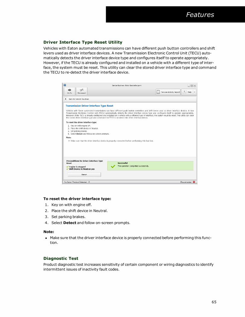
Driver Interface Type Reset Utility
Vehicles with Eaton automated transmissions can have different push button controllers and shift
levers used as driver interface devices. A new Transmission Electronic Control Unit (TECU) auto-
matically detects the driver interface device type and configures itself to operate appropriately.
However, if the TECU is already configured and installed on a vehicle with a different type of inter-
face, the system must be reset. This utility can clear the stored driver interface type and command
the TECU to re-detect the driver interface device.
To reset the driver interface type:
1. Key on with engine off.
2. Place the shift device in Neutral.
3. Set parking brakes.
4. Select Detect and follow on-screen prompts.
Note:
l Make sure that the driver interface device is properly connected before performing this func-
tion.
Diagnostic Test
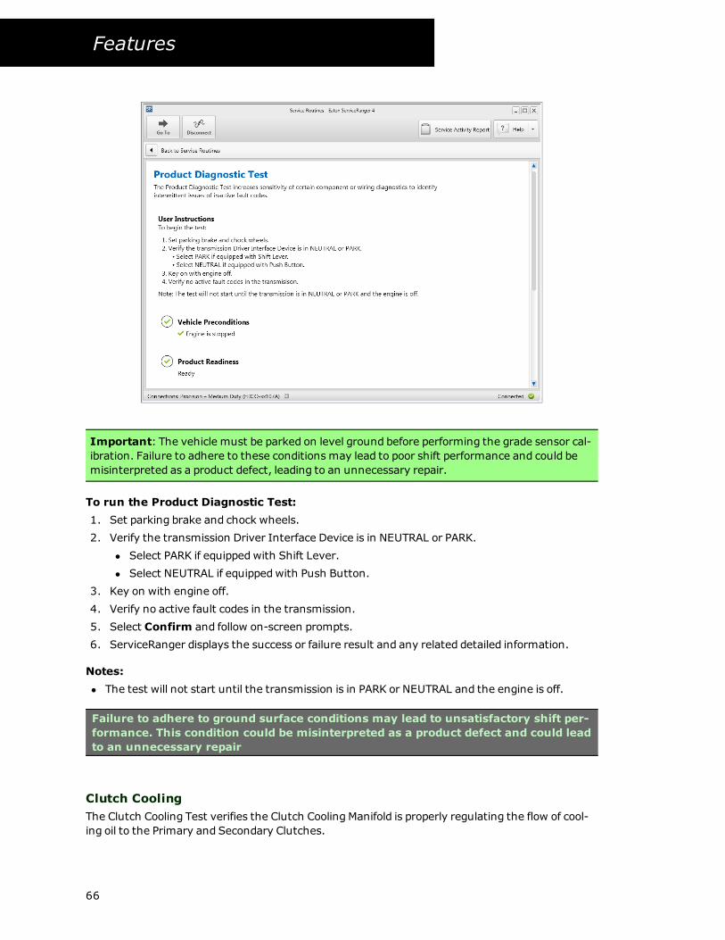
Product diagnostic test increases sensitivity of certain component or wiring diagnostics to identify
intermittent issues of inactivity fault codes.
65
Features
Important: The vehicle must be parked on level ground before performing the grade sensor cal-
ibration. Failure to adhere to these conditions may lead to poor shift performance and could be
misinterpreted as a product defect, leading to an unnecessary repair.
To run the Product Diagnostic Test:
1. Set parking brake and chock wheels.
2. Verify the transmission Driver Interface Device is in NEUTRAL or PARK.
l Select PARK if equippedwith Shift Lever.
l Select NEUTRAL if equippedwith Push Button.
3. Key on with engine off.
4. Verify no active fault codes in the transmission.
5. Select Confirm and follow on-screen prompts.
6. ServiceRanger displays the success or failure result and any related detailed information.
Notes:
l The test will not start until the transmission is in PARK or NEUTRAL and the engine is off.
Failure to adhere to ground surface conditions may lead to unsatisfactory shift per-
formance. This condition could be misinterpreted as a product defect and could lead
to an unnecessary repair
Clutch Cooling
The Clutch Cooling Test verifies the Clutch Cooling Manifold is properly regulating the flow of cool-
ing oil to the Primary and Secondary Clutches.
66

Features
Important: The vehicle must be parked on level ground before performing the grade sensor cal-
ibration. Failure to adhere to these conditions may lead to poor shift performance and could be
misinterpreted as a product defect, leading to an unnecessary repair.
To run the Clutch Cooling Test:
1. Set parking brake and chock wheels.
2. Verify the transmission Driver Interface Device is in NEUTRAL or PARK.
l Select PARK if equippedwith Shift Lever.
l Select NEUTRAL if equippedwith Push Button.
3. Install hydraulic line and gauge in the LP port on the left side of the transmission.
4. Start the engine. Allow engine to run at idle speed (650-1200 RPM).
5. Ensure proper transmission oil level per Service Manual TRSM0990 - Oil Level Inspection
Procedure.
6. Select Begin and follow on-screen prompts.
7. ServiceRanger displays the success or failure result and any related detailed information.
Notes:
l The test will not start until the transmission is in either Neutral or Park and the engine is run-
ning at idle speed.
Failure to adhere to ground surface conditions may lead to unsatisfactory shift per-
formance. This condition could be misinterpreted as a product defect and could lead
to an unnecessary repair
Clutch Disable Valve Test
67

Features
The Clutch Disable Valve (CDT) Test verifies the ability of the control system to control the oil flow
to the Primary and Secondary Clutches.
Important: The vehicle must be parked on level ground before performing the grade sensor cal-
ibration. Failure to adhere to these conditions may lead to poor shift performance and could be
misinterpreted as a product defect, leading to an unnecessary repair.
To run the Clutch Disable Valve Test:
1. Set parking brake and chock wheels.
2. Verify the transmission Driver Interface Device is in NEUTRAL or PARK.
l Select PARK if equippedwith Shift Lever.
l Select NEUTRAL if equippedwith Push Button.
3. Start the engine. Allow engine to run at idle speed (greater than 525 RPM).
4. Ensure the vehicle is stationary.
5. Ensure the transmission oil temperature is higher than 20 C.
6. Ensure proper transmission oil level per Service Manual TRSM0990 - Oil Level Inspection
Procedure.
7. Select Confirm and follow on-screen prompts.
8. ServiceRanger displays the success or failure result and any related detailed information.
Notes:
l The test will not start until the transmission is in either Neutral or Park and the engine is run-
ning at idle speed.
68
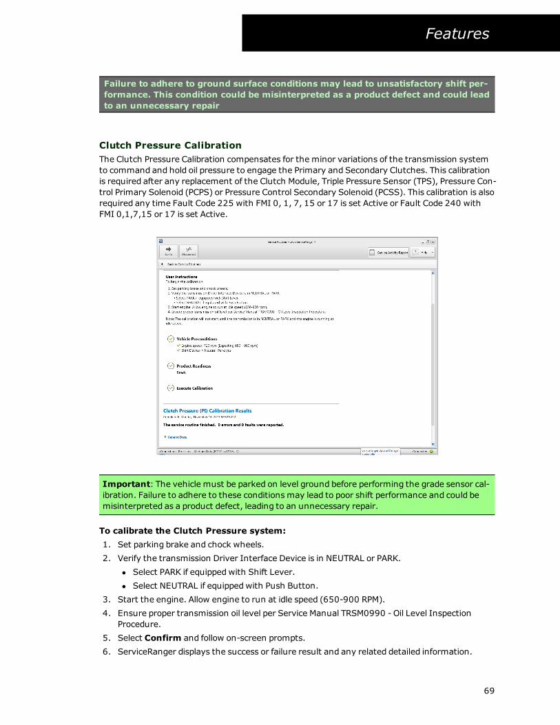
Features
Failure to adhere to ground surface conditions may lead to unsatisfactory shift per-
formance. This condition could be misinterpreted as a product defect and could lead
to an unnecessary repair
Clutch Pressure Calibration
The Clutch Pressure Calibration compensates for the minor variations of the transmission system
to command and hold oil pressure to engage the Primary and Secondary Clutches. This calibration
is required after any replacement of the Clutch Module, Triple Pressure Sensor (TPS), Pressure Con-
trol Primary Solenoid (PCPS) or Pressure Control Secondary Solenoid (PCSS). This calibration is also
required any time Fault Code 225 with FMI 0, 1, 7, 15 or 17 is set Active or Fault Code 240 with
FMI 0,1,7,15 or 17 is set Active.
Important: The vehicle must be parked on level ground before performing the grade sensor cal-
ibration. Failure to adhere to these conditions may lead to poor shift performance and could be
misinterpreted as a product defect, leading to an unnecessary repair.
To calibrate the Clutch Pressure system:
1. Set parking brake and chock wheels.
2. Verify the transmission Driver Interface Device is in NEUTRAL or PARK.
l Select PARK if equippedwith Shift Lever.
l Select NEUTRAL if equippedwith Push Button.
3. Start the engine. Allow engine to run at idle speed (650-900 RPM).
4. Ensure proper transmission oil level per Service Manual TRSM0990 - Oil Level Inspection
Procedure.
5. Select Confirm and follow on-screen prompts.
6. ServiceRanger displays the success or failure result and any related detailed information.
69

Features
Notes:
l The test will not start until the transmission is in PARK or NEUTRAL and the engine is run-
ning at idle speed.
Failure to adhere to ground surface conditions may lead to unsatisfactory shift per-
formance. This condition could be misinterpreted as a product defect and could lead
to an unnecessary repair
Clutch Touch Point Calibration
The Clutch Touch Point Calibration compensates for wear of the physical Primary and Secondary
Clutches, as well as minor system differences of the transmission hydraulic systems to command
and hold oil pressure to engage the Primary and Secondary clutches. This calibration determines
the minimum amount of oil pressure that needs to be applied to push torque through the primary
and secondary clutches.
Important: The vehicle must be parked on level ground before performing the grade sensor cal-
ibration. Failure to adhere to these conditions may lead to poor shift performance and could be
misinterpreted as a product defect, leading to an unnecessary repair.
To calibrate the Clutch Touch Point:
1. Set parking brake and chock wheels.
2. Verify the transmission Driver Interface Device is in NEUTRAL or PARK.
l Select PARK if equippedwith Shift Lever.
l Select NEUTRAL if equippedwith Push Button.
3. Start the engine. Allow engine to run at idle speed (650-900 RPM).
70

Features
4. Ensure proper transmission oil level per Service Manual TRSM0990 - Oil Level Inspection
Procedure.
5. Select Confirm and follow on-screen prompts.
6. ServiceRanger displays the success or failure result and any related detailed information.
Notes:
l The test will not start until the transmission is in PARK or NEUTRAL and the engine is run-
ning at idle speed.
Failure to adhere to ground surface conditions may lead to unsatisfactory shift per-
formance. This condition could be misinterpreted as a product defect and could lead
to an unnecessary repair
Grade Sensor Calibration
The Transmission Control Module (TCM) internal Grade Sensor provides vehicle slope information
to ensure proper vehicle launch, shifting performance and Hill Helper operation. The grade sensor
is initially calibrated at the OEM factory, however this calibration is required after replacement of
the TCM or any time Fault Code 385 with FMI 13 is set Active.
Important: The vehicle must be parked on level ground before performing the grade sensor cal-
ibration. Failure to adhere to these conditions may lead to poor shift performance and could be
misinterpreted as a product defect, leading to an unnecessary repair.
To calibrate the Grade Sensor:
1. Key on with engine off.
2. Verify vehicle is parked on level ground.
71

Features
l Ground surface must be within +/-0.50% grade (+/-0.28 deg) from level.
l Maximum allowable grade is +/-0.87% grade (+/-0.50 deg) from level.
3. Verify the suspension is fully aired (if equipped).
4. Verify the suspension is at proper ride height.
5. Select Confirm and follow on-screen prompts.
6. ServiceRanger displays Success or Fail result.
7. After a successful calibration, key off and allow the TCM to power down.
Notes:
l It may take up to 5 seconds for active fault code 385 FMI 13 to go inactive after calibrating
the Grade Sensor.
Failure to adhere to ground surface conditions may lead to unsatisfactory shift per-
formance. This condition could be misinterpreted as a product defect and could lead
to an unnecessary repair
Line Pressure Calibration
The Line Pressure Calibration adjusts for variances of the transmission system to command and
hold supply oil line pressure across a range of pressure values. This calibration is required after any
replacement of the Transmission Control Module (TCM), Triple Pressure Sensor (TPS), Line Pres-
sure Solenoid (LPS) or Pump Assembly (PA) or any time Fault Code 210 with FMI 13 is set Active.
72

Features
Important: The vehicle must be parked on level ground before performing the grade sensor cal-
ibration. Failure to adhere to these conditions may lead to poor shift performance and could be
misinterpreted as a product defect, leading to an unnecessary repair.
To calibrate Line Pressure:
1. Set parking brake and chock wheels.
2. Verify the transmission Driver Interface Device is in NEUTRAL or PARK.
l Select PARK if equippedwith Shift Lever.
l Select NEUTRAL if equippedwith Push Button.
3. Verify no other faults associated with Line Pressure
4. Start the engine. Allow engine to run at idle speed (650 - 1100 RPM).
5. Ensure proper transmission oil level per Service Manual TRSM0990 - Oil Level Inspection
Procedure.
6. Select Confirm and follow on-screen prompts.
7. ServiceRanger displays the success or failure result and any related detailed information.
Notes:
l The test will not start until the transmission is in PARK or NEUTRAL and the engine is run-
ning at idle speed.
Failure to adhere to ground surface conditions may lead to unsatisfactory shift per-
formance. This condition could be misinterpreted as a product defect and could lead
to an unnecessary repair
Line Pressure Test
The Line Pressure Test sends commands from the Transmission Control Module (TCM) to the Line
Pressure Solenoid and compares the current to hydraulic pressure feedback with the stored values
in the TCM.
73

Features
Important: The vehicle must be parked on level ground before performing the grade sensor cal-
ibration. Failure to adhere to these conditions may lead to poor shift performance and could be
misinterpreted as a product defect, leading to an unnecessary repair.
To run the Line Pressure Test:
1. Set parking brake and chock wheels.
2. Verify the transmission Driver Interface Device is in NEUTRAL or PARK.
l Select PARK if equippedwith Shift Lever.
l Select NEUTRAL if equippedwith Push Button.
3. Verify no other faults associated with Line Pressure
4. Install hydraulic line and gauge in the LP port on the left side of the transmission.
5. Start the engine. Allow engine to run at idle speed (650 - 1100 RPM).
6. Ensure proper transmission oil level per Service Manual TRSM0990 - Oil Level Inspection
Procedure.
7. Select Confirm and follow on-screen prompts.
8. ServiceRanger displays the success or failure result and any related detailed information.
Notes:
l The test will not start until the transmission is in PARK or NEUTRAL and the engine is run-
ning at idle speed.
Failure to adhere to ground surface conditions may lead to unsatisfactory shift per-
formance. This condition could be misinterpreted as a product defect and could lead
to an unnecessary repair
74

Features
Shift Device Calibration
Transmission equippedwith a "T-Handle" style Shift Level uses a cable linkage connected to the
Transmission Range Sensor (TRS). The TRS verifies the transmission achieves the requested shift
mode. The TRS Calibration is used to compensate for the cable adjustment or minor variances in
the TRS. This calibration is required after any installation of a shift cable or replacement of the
Transmission Control Module (TCM), "T-handle" style Shift Lever, TRS or shift cable or any time
Fault Code 135 with FMI 13 is set Active
Important: The vehicle must be parked on level ground before performing the grade sensor cal-
ibration. Failure to adhere to these conditions may lead to poor shift performance and could be
misinterpreted as a product defect, leading to an unnecessary repair.
To calibrate the Shift Device:
1. Set parking brake and chock wheels.
2. Verify the transmission Shift Lever is in PARK.
3. Key on with engine off.
4. Verify vehicle battery voltage is within range (10 to 14 volts).
5. Select Confirm and follow on-screen prompts.
6. ServiceRanger displays the success or failure result and any related detailed information.
Notes:
l The test will not start until the transmission is in PARK and the engine is off.
75

Features
Failure to adhere to ground surface conditions may lead to unsatisfactory shift per-
formance. This condition could be misinterpreted as a product defect and could lead
to an unnecessary repair
Rail Calibration
The Rail Calibration compensates for the minor variances of the transmission system to command
Shift Rails A, B and C into the fore, aft or neutral detent positions, and to command Shift Rail D into
the neutral or aft detent positions. This calibration is required after any replacement of the Action
Control Manifold (ACM), 3-Rail Position sensor, Rail D Position Sensor, Shift Pressure Solenoid 1/2
(SPS1/2), Rail A Valve Solenoid (RAVS), Rail B Valve Solenoid (RBVS), Rail C valve Solenoid (RCVS),
Rail D Valve Solenoid (RDVS), Interface Manifold (IM), Shift Rails or Shift Rail Seals/Pistons.
Important: The vehicle must be parked on level ground before performing the grade sensor cal-
ibration. Failure to adhere to these conditions may lead to poor shift performance and could be
misinterpreted as a product defect, leading to an unnecessary repair.
To calibrate Rail System:
1. Set parking brake and chock wheels.
2. Verify the transmission Driver Interface Device is in NEUTRAL or PARK.
l Select PARK if equippedwith Shift Lever.
l Select NEUTRAL if equippedwith Push Button.
3. Start the engine. Allow engine to run at idle speed (greater than 525 RPM).
4. Ensure proper transmission oil level per Service Manual TRSM0990 - Oil Level Inspection
Procedure.
76

Features
5. Select Confirm and follow on-screen prompts.
6. ServiceRanger displays the success or failure result and any related detailed information.
Notes:
l The test will not start until the transmission is in PARK or NEUTRAL and the engine is run-
ning at idle speed.
Failure to adhere to ground surface conditions may lead to unsatisfactory shift per-
formance. This condition could be misinterpreted as a product defect and could lead
to an unnecessary repair
77

Features
Product information
Product Information Overview
The Product Information feature allows you to view up-to-date service literature such as trou-
bleshooting and service manuals for Eaton products.
Screen Overview
The main screen in Product Information is split into two sections, the navigation tree and the con-
tent area.
Navigation Tree
The navigation tree allows you to navigate to a service publication for viewing. It is organized by
product family then service manual type (e.g. Troubleshooting Guide or Service Manual).
Content Area
The content area displays the service information once selected in navigation menu.
Viewing Product Information
Viewing product information is very similar to using a web browser to navigate the Internet.
78

Features
To view product information:
1. Select Product Information from the navigation menu.
2. The default home screen is displayed.
3. Review the available products in the navigation tree and select a product name.
4. Review the available chapter names, and select a chapter.
5. Review the available titles, and select a title.
6. The information is displayed in the content area.
Note:
l While viewing content, hyperlinks appear when related content is available. For example,
when a troubleshooting procedure indicates to replace a part a hyperlink to the removal and
repair procedure in the service manual is displayed.
Videos
When a video is available an icon is displayed in the content area. Selecting the icon opens the
video in the default video player.
To view a video:
1. Select Product Information from the navigation menu.
2. Select the video icon from the content area.
3. The video is opened in the default video player on your computer.
Note:
l Not all content has a video.
Printing Product Information
Product information content can be printed from ServiceRanger. This allows you to have a paper
copy for reference as you perform a service or troubleshooting procedure.
To print product information:
1. Select Product Information from the navigation menu.
2. View service information content.
3. Select Print.
4. In the Print dialog, complete the options and select Ok.
79

Features
80

Features
Reports
Reports Overview
ServiceRanger allows you to create reports of vehicle-related service and diagnostic information.
This is useful when you need to save information for review at a later time. There are two types of
reports, Diagnostic and Service Activity.
Diagnostic Reports
A diagnostic report contains vehicle identification information, fault codes, and current software
levels. The report can be printed, saved to PDF, or emailed (using your default email client). The
report data comes from the currently connected vehicle, or alternatively a saved Service Activity
Report.
Service Activity Reports
Service activity reports contain information on vehicle identification information, fault codes, con-
figuration settings, software levels, troubleshooting steps, and results of service routines. The infor-
mation is savedwithin ServiceRanger allowing you to perform searches and share the information
with Eaton support representatives. Additionally, the information can be used to create a diag-
nostic report in either printed or pdf format.
Diagnostic Reports Overview
The diagnostic report feature allows you to quickly create, save, and print information when con-
nected to a vehicle.
Report Overview
The diagnostic report is split into two sections, the report details and the report content area.
Report Header
The report header section provides information on vehicle identification, vehicle mileage, and the
date the report was created.
Report Detail Area
The content area displays the information from the vehicle. This includes fault code information,
software versions, and any notes you may have entered for example.
81

Features
Printing Diagnostic Report
You can quickly create and print a diagnostic report from ServiceRanger. When you print infor-
mation, it is displayed in a formatted report. The Print Preview feature allows you to see how a
printed report looks and to adjust page orientation, scaling, andmargins, etc before printing.
To print a report:
1. View a content area (e.g. fault code, configurations).
2. Select Print icon from the toolbar.
3. In the report option dialog, enter any information that you would like to include.
4. Select Ok.
5. The print preview dialog is displayed.
6. Select Print to send the information to your printer.
Notes:
l The Print Preview window has a number of buttons and other controls enabling you to zoom
the display, view different pages, etc.
l The Print Preview window also has options to export and email your information.
82

Features
l Notes, Fault Codes, Vehicle Components, and Product Configuration information are
included into the report.
Export and Email Diagnostic Report
Information displayed in ServiceRanger can be exported, or saved, with a diagnostic report. Fault
codes, configuration settings, software versions, and notes can be exported to a PDF file. There is
also an option allowing you to easily attach a report and send it by email.
To export a diagnostic report:
1. View a content area (e.g. fault code, configurations).
2. Select the Export icon from the toolbar.
3. In the report option dialog, enter any information to be included in the report.
4. In the save file dialog, select the location to save the report on your computer.
Notes:
l A default filename is supplied based on date and time. The filename can be changed.
l By default, the report is saved in the "My Documents" folder.
To export and email a report:
1. View a content area (e.g. fault code, components).
2. Select the Export and Email icon from the toolbar.
3. In the report option dialog, enter any information to be included in the report.
4. In the save file dialog, select the location to save the report on your computer.
5. Select Save.
6. Your default email program is opened and the report is attached.
Notes:
l A default filename is supplied based on date and time. The filename can be changed.
l By default, the report is saved in the "My Documents" folder.
Service Reports Overview
The service reports feature allows you to create and view reports of vehicle information, fault his-
tory, and other service activity and actions you performedwhen working in ServiceRanger.
Screen Overview
The service report screen is split into two sections, the report details and the report content area.
Report Detail
The report detail section provides information on vehicle identification, vehicle mileage, and the
date the report was created.
Report Content Area
The content area displays the information ServiceRanger records while connected to the vehicle.
This includes fault code information, snapshot data, and any notes you may have entered for
83

Features
example. Each section of information can be viewed by selecting the Viewing drop down.
Starting a New Service Report
At any point while connected to a vehicle, you can start a Service Activity Report. ServiceRanger
asks you to provide some basic vehicle information and then begins the process of retrieving infor-
mation from the vehicle. Information is added, or appended, to the report as you use Serv-
iceRanger. This allows you to have all the information collected in one report as you work and
perform the service troubleshooting and repair activities.
To start a new service report:
1. Select Service Activity Report from the navigation menu.
2. Enter the following information:
l Vehicle Identification Number (VIN) - required
l Repair Order - required
l Odometer
l Owner
l Vehicle in-service-date
l Unit Number
l Vehicle Vocation
l Technician Name - required
l Service Notes
3. Select Start Report.
4. The system retrieves information from the vehicle, which may take a few minutes.
5. Once completed, the Service Report is created and displayed.
84

Features
Notes:
l You can not create a service report while disconnected to the vehicle.
l The system attempts to retrieve the VIN and odometer from the vehicle automatically. If
not, you are required to enter the information.
l If you have a saved service report for the current vehicle, the system attempts to auto com-
plete some information such as vocation, unit number, etc.
Resuming a Paused Service Report
While working on a vehicle it may become necessary to pause a report and resume it at a later date
and time to complete the repair. This is useful if you are working on multiple vehicles or waiting for
parts on order for example.
If you start a new report, ServiceRanger will attempt to retrieve the VIN from the vehicle. If a
report in the paused state contains the retrieved VIN, ServiceRanger will prompt you to either con-
tinue the current report or close the existing report and start a new one. However, there are time
when the VIN can not be automatically retrieved from the vehicle. Therefore it may be necessary
to manually resume a report to add new information.
To manually resume a paused service report:
1. Connect to a vehicle.
2. Select Service Activity Report from the navigation menu.
3. Locate the paused report you want to resume.
4. Select Resume.
5. The Service Report is updatedwith the new information and displayed.
85

Features
Notes:
l You can not resume a closed service activity report.
l The system attempts to retrieve the VIN from the vehicle automatically. If the vehicle VIN
does not match the VIN in the service activity report, you are prompted to confirm if the
report matches the vehicle.
Viewing a Saved Report
You can quickly access saved reports in ServiceRanger by navigating to the main landing screen in
the Service Activity Report feature. A list of saved Service Reports is displayed. In addition, there
are also features available to search the saved reports by VIN, repair order, and technician name.
To view a saved service report:
1. Select Service Activity Report from the navigation menu.
2. The Index page is shown with a list of saved Service Activity Reports, most recent first.
3. Select View to view the desired report.
4. The report opens and is displayed in a new tab.
86

Features
Search
Search allows you to quickly find saved reports. The searched fields include VIN, repair order, and
technician name.
To search for a saved service report:
1. Select Service Activity Report from the navigation menu.
2. Enter the criteria in the search field.
3. The result of the search is displayed.
4. Select View to view the desired report.
5. The report is opened and is displayed in a new tab.
87

Features
Working with a Service Report
When you open a service activity report, you will notice several pieces of information. At the top of
the report, is the report header. It contains information about the vehicle and the repair. Below
the header is the content area. The content area contains information such as fault codes, con-
figuration settings, and snapshot data.
88

Features
To change the information displayed:
1. Open a Service Activity Report.
2. The report is displayed, with the fault code view as the default information being displayed.
3. Select one of the following from the selection list:
l Service Notes
l Eaton fault codes
l Vehicle fault codes
l Vehicle components
l Configurations
l Programming
4. The selected view is displayed.
Notes:
l The view selection menu changes based on the type of information recorded from the
vehicle at the time the report was created. Some of the options may not be present.
To find a related reports:
1. Open a Service Activity Report.
2. The report is displayed.
3. Select Find Related from the toolbar.
4. The search dialog is displayedwith results that match the VIN of the current report.
To close a open report:
1. Open a Service Activity Report.
2. The report is displayed.
89

Features
3. Select Close.
4. The report is marked closed and can not be re-opened and changed.
Notes:
l Only opened or paused reports can be closed.
To print a report:
1. Open a Service Activity Report.
2. The report is displayed.
3. Select Print from the toolbar.
4. The print preview dialog is displayed.
5. Select Print to send the information to your printer.
Notes:
l The Print Preview window has a number of buttons and other controls enabling you to zoom
the display, view different pages, etc.
l The Print Preview window also has options to export and email your information.
l Notes, Fault Codes, Vehicle Components, and Product Configuration information are
included into the report.
To export a report:
1. Open a Service Activity Report.
2. The report is displayed.
3. Select Export from the toolbar.
4. In the save file dialog, select the location to save the report on your computer.
Notes:
l A default name is supplied based on date and time. You can change the file name.
l By default, the report is saved in the "My Documents" folder.
How to export and email a report:
1. Open a Service Activity Report.
2. Select Export and Email from the toolbar.
3. In the save file dialog, select the location to save the report on your computer.
4. Select Save.
5. Your default email program opens and the report is attached.
Notes:
l A default name is supplied based on date and time. You can change the file name.
l By default, the report is saved in the "My Documents" folder.
To delete a report:
1. Open a Service Activity Report.
2. The report is displayed.
3. Select Delete from the toolbar.
4. Select Ok on the confirmation dialog.
5. The report is deleted from your computer.
90

Features
Notes:
l This operation can not be un-done.
Send Data to Eaton
The send to Eaton feature allows you to easily transfer information to an Eaton representative for
advanced troubleshooting help. The information stored in the Service Activity Report, including
fault codes, configuration settings, software versions , snapshot and VPA information is uploaded.
To send data
1. Connect to the Internet.
2. View the Service Activity Report you want to share.
3. Select Send to Eaton from the menu bar.
Notes:
l The computer must have Internet access for the Data Upload function to work properly.
91

Features
Settings
To set preferences on how ServiceRanger operates, you can change various settings to fit your
needs.
To open the settings dialog
1. Select Settings on the navigation menu.
Connection Settings
The connection settings page allows you to choose either simulation mode or vehicle connection.
In the case of vehicle it allows you to choose the vehicle communication adapter you are using to
connect to the vehicle. For simulation, it allows you to simulate a particular Eaton product. This is
useful for training purposes.
To set simulation mode:
1. Select Simulation.
2. Select the product in the drop product selection drop down list (e.g. AutoShift/UltraShift
Gen3).
3. Select communication link in the connection links drop down list.
4. Select Apply.
5. The system is now configured for simulation mode, as indicated by the red border. You can
use the application as if you were connected to the vehicle.
To set vehicle mode and select a communication adapter:
92
Features
1. Select Vehicle.
2. Select the Communication Adapter in the drop down list.
Note: If you do not see the driver for your adapter in this list, your driver may not be
installed correctly. If you are unsure about how to install these drivers, or you do not
know which driver to select, contact the manufacturer of your communications adapter
for more information.
3. Select the computer connection method from the J1587 Device drop down list.
4. Select the computer connection method from the J1939 Device drop down list.
Note: The J1939 list will contain the available connections for your communication adapt-
ers. The list is displayed as connection method, then channel, then connection speed.
Refer to your vehicle's OEM for more information on the correct connection speed and
channel.
5. Once the connection settings have been made, select Apply to save your choices and
return to the main screen. ServiceRanger remembers the connection settings each time it
is started.
Notes:
l If a vehicle communication adapter is configured and has not been approved by Eaton, pro-
gramming functions are not allowed to be performed. Amessage is displayed if you select a
communication adapter that is not supported.
l J1939 connection methods vary by OEMs, newer vehicles may require channel 2 to be
selected. Refer to Roadranger.com for more information.
l Only select the ‘auto’ setting if your communication adapter supports the auto baud detec-
tion of the link speed. Please refer to your communication adapter manufacturer for more
information.
Update Status
The update status page allows you to view the current product configurations and software on
your PC. This is useful to very you have the correct software and configurations before connecting
to a vehicle.
93

Features
To view product software for programming:
1. Select the product in the drop product selection drop down list (e.g. UltraShift PLUS).
2. Select the model in the drop down list (e.g. FM-xxE310-LAS).
3. Select the Programming tab.
4. The available software will be shown.
To view available configurations and settings:
1. Select the product in the drop product selection drop down list (e.g. UltraShift PLUS).
2. Select the model in the drop down list (e.g. FM-xxE310-LAS).
3. Select the Configurations tab.
4. The available configurations will be shown.
5. Select the configuration item to display list of available settings.
General
The general page allows you to view and update your viewing preferences.
94

Features
Selecting a unit of measure for the user interface
You may need to change how data values (e.g. road speed in mph or km/h) are displayed based on
unit of measure. ServiceRanger provides two different settings - standard andmetric.
To change unit of measure:
1. Select General on the setting screen.
2. Select Standard or Metric.
3. Select Apply.
Notes:
l You will need to restart ServiceRanger for the setting to take effect.
Selecting a language for the user interface
You have the option of viewing the interface in different languages. All of these languages are avail-
able from the same version of ServiceRanger (you do not need to purchase different versions for dif-
ferent languages). When you initially launch ServiceRanger, you are asked to select your language
preferences. Based on your selection, the user interface is displayed in the appropriate language,
with the option to later switch your preferences at any time from the language selection dialog. If,
for any reason, a particular element is not available in that language, the element displays in the
default language, English.
To change displayed language/culture:
1. Select General on the setting screen.
2. Select a language and culture setting from the selection list.
3. Select Apply.
License
95

Features
The license page allows you to view and update your license information. Licenses control what fea-
tures and functions that are available to you. Included in this information is your license status
and expiration date.
To upgrade a license:
1. Connect to the Internet.
2. Select License on the setting screen.
3. Enter your new upgrade code.
4. Select Upgrade.
Notes:
l You must have an Internet connection available when upgrading a license.
To copy license information to the clipboard:
1. Select License on the setting screen.
2. Select theCopy icon.
3. The information is copied to the clipboard and can be pasted into another software appli-
cation.
Support
The support page allows you to troubleshoot issues that you may be having with ServiceRanger.
You should only change settings on this page when instructed to by an Eaton representative.
96

Features
Update Manager
The ServiceRanger update manager provides notifications of updates to ServiceRanger. Keeping
your software up-to-date is important and allows you to get the most out of your diagnostic tool.
The update service runs in the background of your computer and does not interfere with your daily
work.
Check for updates
You can use the check for updates feature to download and install any available updates for Serv-
iceRanger. In order to do this, the computer must be connected to the Internet.
To manually check for updates:
1. Select check for updates:
l From within ServiceRanger, select Check for updates now from the home
screen.
OR
l From the system tray, right click on the ServiceRanger update manger icon
and select Check for Updates.
2. A dialog is displayedwhile the system connects to the Internet and checks for updates.
3. If an update is found, the Update Manager will automatically download the update.
4. The update is downloaded and the installation is started. Follow the screen prompts to fin-
ish the update.
Notes:
l The update service uses standard Internet protocols and ports to check for updates.
l Some firewall and IT services may block the website the update service needs to access to
check for updates. Port 80 should be open and the followingwebsite should be added to their
white list: *serviceranger4.com
97

Support
Support
Technical Support
Visit Roadranger.com for more information about ServiceRanger, including updates, service bul-
letins, and other frequently asked questions.
If you need assistance you can call Roadranger Technical Assistance Call Center at 1-800-826-
HELP (4357). The following information may be required to help resolve any issues you may be
having, so have this information readily available before calling:
l The ServiceRanger software version numbers found in the Help\About ServiceRanger
screen.
l Your computer operating system.
l Your Vehicle Communications Adapter make, model, and RP1210 driver version.
l Exact wording of any error or warningmessage you may have received from the program.
l Sequence of steps you took before any errors occurred.
l Any changesmade to your computer recently, including new software or peripherals, and if
the ServiceRanger program was running correctly in the past.
98


Copyright Eaton, 2015. Eaton hereby grant their customers, vendors, or distributors permission to freely copy, reproduce and/or distribute this document in printed format. It may be copied only in its entirety without any changes or modifications. THIS INFOR-MATION IS NOT INTENDED FOR SALE OR RESALE, AND THIS NOTICE MUST REMAIN ON ALL COPIES.
Note: Features and specifications listedin this document are subject to changewithout notice and represent the maxi-mum capabilities of the software andproducts with all options installed.Although every attempt has been madeto ensure the accuracy of informationcontained within, Eaton makes no repre-sentation about the completeness, cor-rectness or accuracy and assumes noresponsibility for any errors or omis-sions. Features and functionality mayvary depending on selected options.
For spec’ing or service assistance, call1-800-826-HELP (4357) or visitwww.eaton.com/roadranger.In Mexico, call 001-800-826-4357.
Roadranger: Eaton and trusted partnersproviding the best products and ser-vices in the industry, ensuring moretime on the road.
Eaton CorporationVehicle GroupP.O. Box 4013Kalamazoo, MI 49003 USA800-826-HELP (4357)www.eaton.com/roadranger
Printed in USA