Embed Size (px)
Citation preview

A SERVICE PUBLICATION OFLOCKHEED-GEORGIA COMPANYA DIVISION OFLOCKHEED CORPORATION
EditorCharles I. Gale
Associate EditorsDoug BrashearJames A. LoftinVera A. Taylor
Art Direction & ProductionTeri L. Mohr
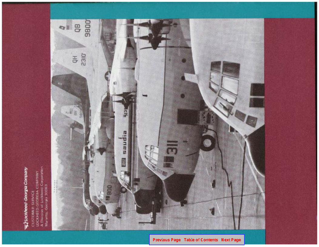
Cover: The Lockheed-Georgia Company flightline in Marietta, Georgia. Over 1800 Herculesaircraft have now been built, in more than 40different versions. These remarkable airlifterscontinue in full production; three new ones arerolled out at the factory each month.
M. M. HODNETT DIRECTOR
CUSTOMER INTEGRATED CUSTOMERSERVICE LOGISTICS SUPPORT SUPPLY
A H McCurm . I L> Thurmond ii i N i ss l ey
DIRECTOR DIRECTOR Director

by Bob McRay, Service Representative
Most maintenance personnel know that there are atleast fifteen items on a Hercules aircraft nose landinggear that can cause or contribute to nose wheel shim-my. The problem is how to go about isolating the shim-my to an item, component, or area without expendingconsiderable time and effort on costly trial and erroradjustments and replacements.
One method that has been used quite successfully inthe field requires the assistance of a flight crew, but en-
tails only a taxi run during which a couple of observa-tions arc made and recorded. It is accomplished asfo11ows:
Taxi the aircraft at a speed just sufficient to allow thenose wheels to bc lifted off the ground (just a fewseconds will do), and make these notations:
1. Did the shimmy stop while the nose wheels wereoff the ground or did it continue?
Lockheed SERVICE NEWS V12N4 3

2. During taxi run with the wheels on the ground,did the steering wheel pointer move back and forthrapidly during shimmy or was it relatively steady?
Note that if repeated taxi runs are necessary, thebrakes should be allowed to cool between runs. It is alsoworth noting that the taxi check operation may notalways be necessary. Some flight crews will make thesechecks for you when the problem first occurs and recordtheir findings in the flight forms.
With the taxi runs completed, return to the work areaand look at your notes.
l If the shimmy continued with the wheels off theground, wheel or tire imbalance is indicated. Check forworn spots on the tires and any other condition on thewheels or tires that may contribute to an unbalancedcondition. Note that recapped tires, if used in your
4
organization, should hc highly suspect. It is sometimesa difficult task to balance recapped tires.
There is also a possibility that there may be water inthe tires. If your facility uses compressed air to servicethe tires rather than dry nitrogen, a faulty compressordehydrator filter could introduce water into the tires.This problem can result in some tricky troubleshootingsince sustained vibration would most likely occur onlywhen the water is frozen. This could happen after aflight at high altitude of a duration sufficient to freezethe water and result in vibration upon landing. Similarly,during operation in cold climates, the problem wouldshow up repeatedly during takeoffs and landings. Notethat a brief period of severe vibration may be noticedupon touchdown during landing even if the water is inthe liquid state. It takes a couple of tire rotations todisperse the water equally around the inside of the tire.This is a handy fact to keep in mind whentroubleshooting these problems.
l If the shimmy ceased at nose wheel liftoff, then theobservations noted in item 2 during the taxi run mustbe considered:
l If the shimmy produced no noticeable movement atthe steering wheel pointer with wheels on the ground,looseness caused by excessive wear in mechanical com-
Lockheed SERVICE NEWS V12N4

ponents is indicated. First check the torque arms(scissors). The upper, lower, and center attach bolts andbushings are subject to wear. If the wear is excessive,it will cause a violent shimmy at all speeds up to liftoff.Special attention should be given to the fact that eventhough one bolt or bushing location may be found tobe within wear tolerances, it is the sum of the wear onall the associated bolts and bushings that must be ofconcern. Next check the steering actuator rod endbearings for wear and bolts for security of mounting.Last, and this will require jacking the nose of the air-craft, check for worn wheel bearings and correct axlenut torque.
If thesteering wheelpointer did move buck and forthduring the shimmy, a problem involving the steering con-trol valve is indicated. Here is why. The steering controlvalve is unique in that it will accept steering commandsfrom either the steering wheel or from the nose gear,permitting certain types of shimmy to be transmittedback through the valve to the steering pointer. Since thepointer is connected directly to the steering control valveshaft by the rocker arm and cables, it will be displacedanytime the shaft is displaced. Steering wheel pointermovement during shimmy narrows our check to twoareas: tires and control valve.
l Check the tires. Uneven tire pressure and dissimilaror faulty tread designs tend to make a tire move in ir-regular patterns. This uneven movement is transmittedthrough the scissors to the control valve and, as speedincreases, so does the uneven movement or shimmy.
l Next, check the steering control valve itself. The reliefvalve could be malfunctioning. One method of check-ing the condition of this valve is to remove the plug (item4, Figure 3, T.O. 4SA3-26-3) in the manifold side of thesteering valve and install an MS21916D6-4 reducer,MS28762-4 hose, P/N 695767-l snubber, appropriateadapter, and a O-500 psi pressure gage (see illustration).Disconnect the scissors and, using hydraulic pressurefrom the auxiliary system, rotate the steering mechanismby turning the steering wheel at a very slow but con-stant rate of turn from center to extreme. This shouldtake approximately 10 seconds. Pressure on the gageshould be maintained at 70 + 20 psi, the springaccumulator pressure setting.
Pressure readings outside these limits indicate a stickyor leaking relief valve assembly. Since the valve is anintegral part of the spring-loaded accumulator, repairrequires replacement of the complete steering controlvalve.
Lockheed SERVICE NEWS V12N4
In summary:
I. Shimmy with wheels off the ground means tire orwheel imbalance.
2. Shimmy with wheels on the ground and no pointermovement indicates bolts, bushings, and bearingsworn.
3. Shimmy with wheels on the ground with pointermovement could be a result of steering controlvalve problems, uneven tire pressures, tread im-perfections, or dissimilar tread designs.
Troubleshooting shimmy problems can be com-plicated and time-consuming undertaking if not ap-proached systematically. But if you first review the fun-damentals of nose gear and steering mechanism opera-tion, and then apply the steps described in this pro-cedurc, you should be able to solve most nose landinggear shimmy problems you encounter quickly andeffectively.
5
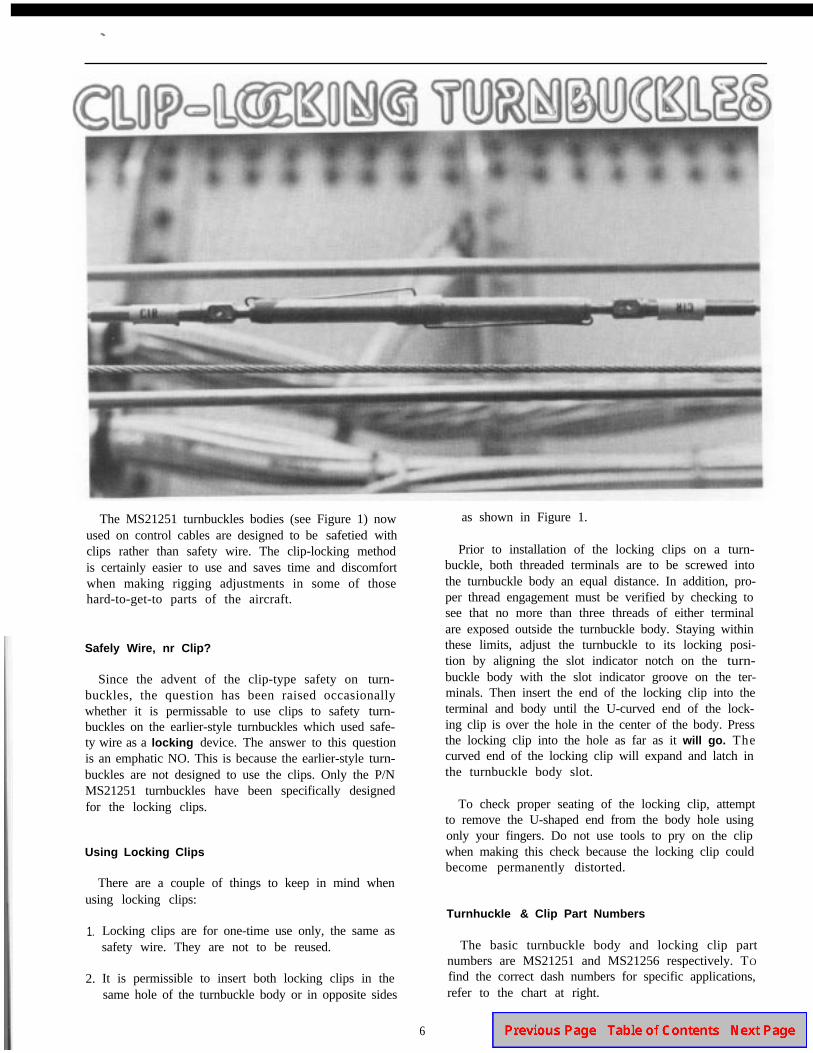
The MS21251 turnbuckles bodies (see Figure 1) nowused on control cables are designed to be safetied withclips rather than safety wire. The clip-locking methodis certainly easier to use and saves time and discomfortwhen making rigging adjustments in some of thosehard-to-get-to parts of the aircraft.
Safely Wire, nr Clip?
Since the advent of the clip-type safety on turn-buckles, the question has been raised occasionallywhether it is permissable to use clips to safety turn-buckles on the earlier-style turnbuckles which used safe-ty wire as a locking device. The answer to this questionis an emphatic NO. This is because the earlier-style turn-buckles are not designed to use the clips. Only the P/NMS21251 turnbuckles have been specifically designedfor the locking clips.
Using Locking Clips
There are a couple of things to keep in mind whenusing locking clips:
1.
2.
Locking clips are for one-time use only, the same assafety wire. They are not to be reused.
It is permissible to insert both locking clips in thesame hole of the turnbuckle body or in opposite sides
as shown in Figure 1.
Prior to installation of the locking clips on a turn-buckle, both threaded terminals are to be screwed intothe turnbuckle body an equal distance. In addition, pro-per thread engagement must be verified by checking tosee that no more than three threads of either terminalare exposed outside the turnbuckle body. Staying withinthese limits, adjust the turnbuckle to its locking posi-tion by aligning the slot indicator notch on the turn-buckle body with the slot indicator groove on the ter-minals. Then insert the end of the locking clip into theterminal and body until the U-curved end of the lock-ing clip is over the hole in the center of the body. Pressthe locking clip into the hole as far as it will go. Thecurved end of the locking clip will expand and latch inthe turnbuckle body slot.
To check proper seating of the locking clip, attemptto remove the U-shaped end from the body hole usingonly your fingers. Do not use tools to pry on the clipwhen making this check because the locking clip couldbecome permanently distorted.
Turnhuckle & Clip Part Numbers
The basic turnbuckle body and locking clip partnumbers are MS21251 and MS21256 respectively. TO
find the correct dash numbers for specific applications,refer to the chart at right.
6 Lockheed SERVICE NEWS V12N4
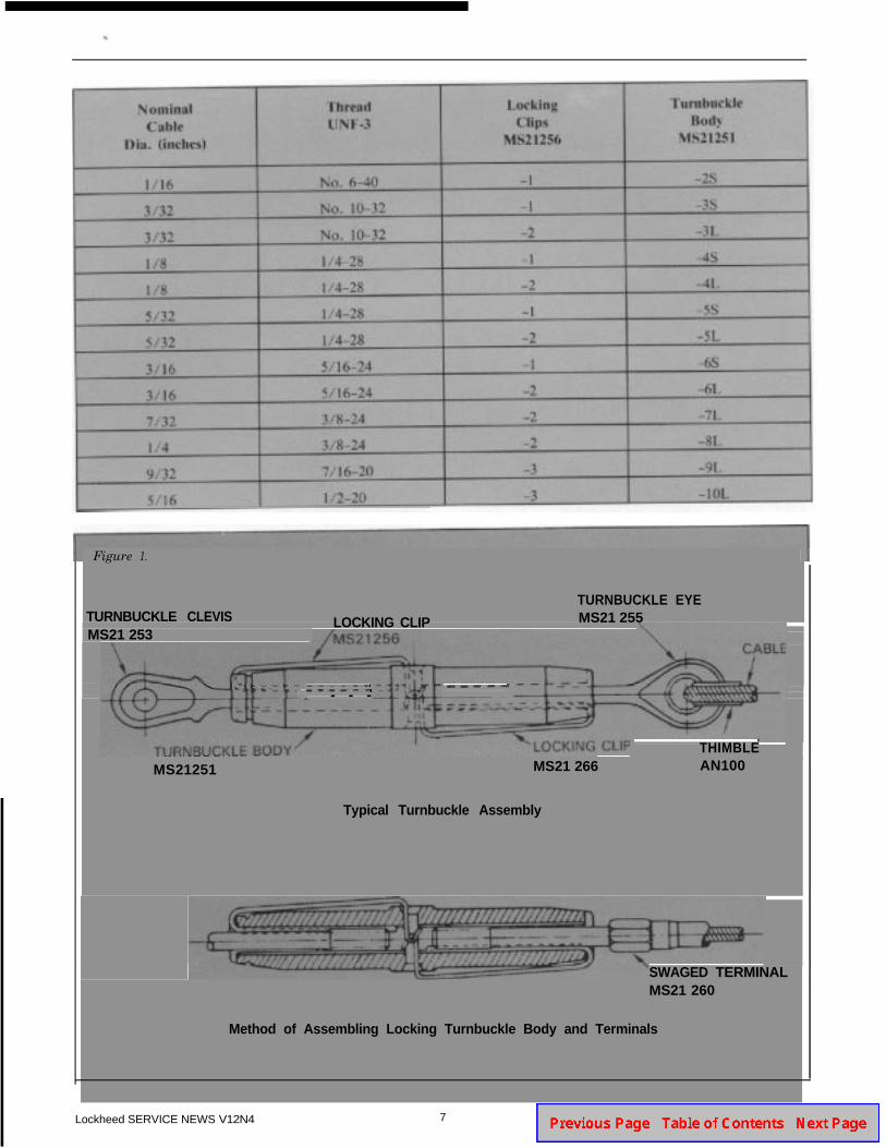
Figure 1.
TURNBUCKLE CLEVISMS21 253
LOCKING CLIP
TURNBUCKLE EYEMS21 255
- - -
THIMBLE
MS21251 MS21 266 AN100
Typical Turnbuckle Assembly
SWAGED TERMINALMS21 260
Method of Assembling Locking Turnbuckle Body and Terminals
Lockheed SERVICE NEWS V12N4 7

HOW TORELEASE A LOCKED LLER BRAKE
by Dare1 A. Traylor, Service Analyst
The function of the propeller brake is to preventaerodynamic forces from causing a feathered propellerto rotate the engine in a direction opposite its normalrotation. It also serves to decelerate the engine and pro-peller during normal shutdown.
The propeller brake has three modes of operation:
Applied operation is the normal static condition forthe brake. It is spring-loaded to this position. Thebrake is applied as engine RPM and oil pressuredecay during a normal shutdown.
Released operation occurs when starter torque over-comes spring force and disengages the brakemembers. This happens at engine start, and the brakeis then held released by oil pressure until shutdown.
A locked propeller brake condition occurs when aforce is applied which tends to rotate the propellerin the direction opposite to its normal rotation. Thisordinarily occurs only through the action ofaerodynamic forces on a feathered propeller in flight,since the blade angle in feather is slightly greater thantrue aerodynamic feather. Normally, an engine thathas been feathered in flight will rotate without inci-dent during an air start or ground operation. Occa-sionaly, however, a propeller brake may remainlocked, preventing the engine from rotating normallyduring start attempts. The most common reasons forthis occuring are:
I . Application of excessive force in the reverse direc-tion of rotation by overzealous personnel check-ing for proper propeller brake operation.
2. Insufficient oil pressure to the prop brake afterengine start, causing the brake to be applied afterstarter disengagement. This results in considerableheating of the propeller brake components. Aftershutdown, the uneven cooling and contraction ofthe inner and outer brake cones can cause the propbrake to lock.
3. High airspeeds in flight with a feathered engine.This tends to drive the propeller opposite itsnormal direction of rotation, and forces the pro-peller brake friction surfaces together ever moretightly, which may result in severe locking of theprop brake.
8 Lockheed SERVICE NEWS V12N4
A locked propeller brake can prove quite a challengeto the maintenance personnel whose job it is to get thebrake released and return the aircraft to operationalstatus promptly. Although it only happens occasionally,knowing the proper techniques for releasing a locked
9
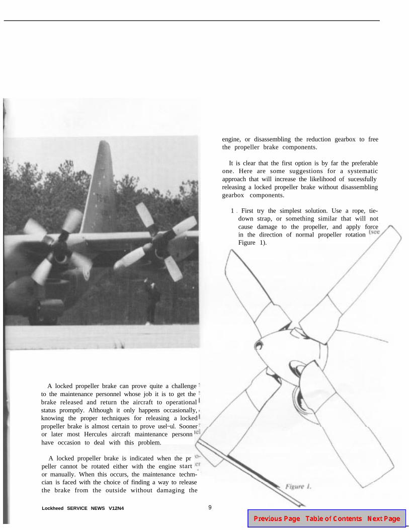
engine, or disassembling the reduction gearbox to freethe propeller brake components.
It is clear that the first option is by far the preferableone. Here are some suggestions for a systematicapproach that will increase the likelihood of sucessfullyreleasing a locked propeller brake without disassemblinggearbox components.
1 . First try the simplest solution. Use a rope, tie-down strap, or something similar that will notcause damage to the propeller, and apply forcein the direction of normal propeller rotationFigure 1).
propeller brake is almost certain to prove usel~ul. Sooneror later most Hercules aircraft maintenance personnhave occasion to deal with this problem.
A locked propeller brake is indicated when the prpeller cannot be rotated either with the enginestartor manually. When this occurs, the maintenance techm-cian is faced with the choice of finding a way to releasethe brake from the outside without damaging the
Lockheed SERVICE NEWS V12N4
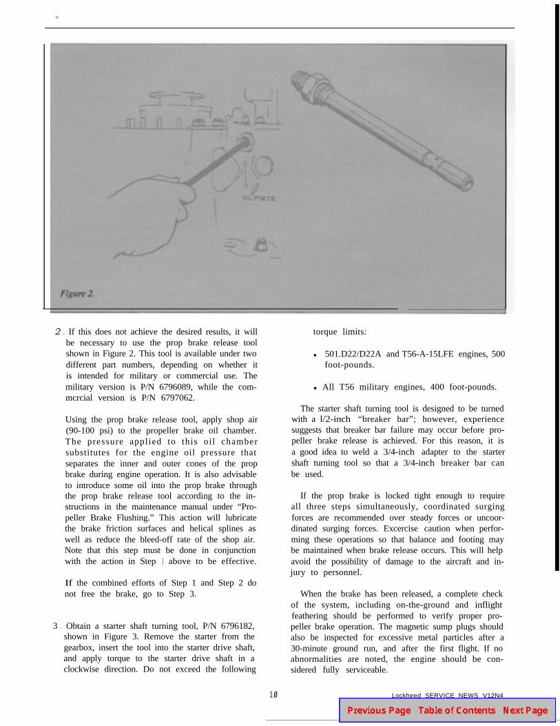
2 . If this does not achieve the desired results, it willbe necessary to use the prop brake release toolshown in Figure 2. This tool is available under twodifferent part numbers, depending on whether itis intended for military or commercial use. Themilitary version is P/N 6796089, while the com-mcrcial version is P/N 6797062.
torque limits:
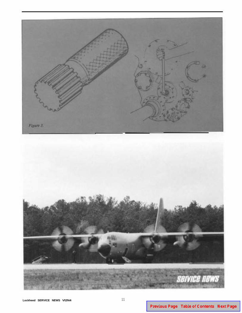
l 501.D22/D22A and T56-A-15LFE engines, 500foot-pounds.
l All T56 military engines, 400 foot-pounds.
Using the prop brake release tool, apply shop air(90-100 psi) to the propeller brake oil chamber.The pressure appl ied to this oi l chambersubstitutes for the engine oil pressure thatseparates the inner and outer cones of the propbrake during engine operation. It is also advisableto introduce some oil into the prop brake throughthe prop brake release tool according to the in-structions in the maintenance manual under “Pro-peller Brake Flushing.” This action will lubricatethe brake friction surfaces and helical splines aswell as reduce the bleed-off rate of the shop air.Note that this step must be done in conjunctionwith the action in Step 1 above to be effective.
The starter shaft turning tool is designed to be turnedwith a l/2-inch “breaker bar”; however, experiencesuggests that breaker bar failure may occur before pro-peller brake release is achieved. For this reason, it isa good idea to weld a 3/4-inch adapter to the startershaft turning tool so that a 3/4-inch breaker bar canbe used.
If the prop brake is locked tight enough to requireall three steps simultaneously, coordinated surgingforces are recommended over steady forces or uncoor-dinated surging forces. Excercise caution when perfor-ming these operations so that balance and footing maybe maintained when brake release occurs. This will helpavoid the possibility of damage to the aircraft and in-jury to personnel.
If the combined efforts of Step 1 and Step 2 donot free the brake, go to Step 3.
3 . Obtain a starter shaft turning tool, P/N 6796182,shown in Figure 3. Remove the starter from thegearbox, insert the tool into the starter drive shaft,and apply torque to the starter drive shaft in aclockwise direction. Do not exceed the following
When the brake has been released, a complete checkof the system, including on-the-ground and inflightfeathering should be performed to verify proper pro-peller brake operation. The magnetic sump plugs shouldalso be inspected for excessive metal particles after a30-minute ground run, and after the first flight. If noabnormalities are noted, the engine should be con-sidered fully serviceable.
10 Lockheed SERVICE NEWS V12N4
Lockheed SERVICE NEWS Vl2N4 11
""""'J.
LIQUID’OXYGENOVERBOARDVENT FITTING
8’ SECTIONHOSE
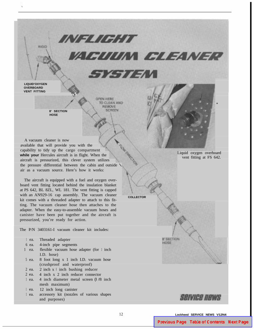
A vacuum cleaner is nowavailable that will provide you with thecapability to tidy up the cargo compartmentwhile your Hercules aircraft is in flight. When theaircraft is pressurized, this clever system utilizesthe pressure differential between the cabin and outside \air as a vacuum source. Here’s how it works:
The aircraft is equipped with a fuel and oxygen over-board vent fitting located behind the insulation blanketat PS 642, BL 8ZL, WL 181. The vent fitting is cappedwith an AN929-16 cap assembly. The vacuum cleanerkit comes with a threaded adapter to attach to this fit-ting. The vacuum cleaner hose then attaches to theadapter. When the easy-to-assemble vacuum hoses andcanister have been put together and the aircraft ispressurized, you’re ready for action.
The P/N 3403161-I vacuum cleaner kit includes:
1 ea.6 ea.
1 ea.
5 ea.
2 ea.2 ea.1 ea.
1 ea.1 ea.
Threaded adapter4-inch pipe segmentsflexible vacuum hose adapter (for 1 inchI.D. hose)8 foot long x 1 inch I.D. vacuum hose(crushproof and waterproof)2 inch x I inch bushing reducer4 inch x 2 inch reducer connector4 inch diameter metal screen (I /8 inchmesh maximum)12 inch long canisteraccessory kit (nozzles of various shapesand purposes)
*
Liquid oxygen overboardvent fitting at FS 642.
COLLECTOR
12 Lockheed SERVICE NEWS V12N4

by Frederick L. Beach, Jr., Service Representative
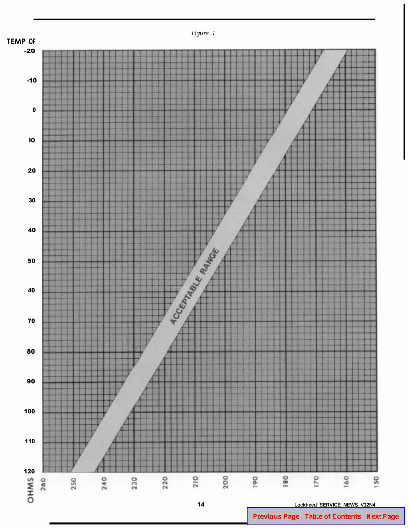
The forward cargo compartment and flight stationtemperature control systems on later model Hercules air-craft utilize all solid-state control boxes and resistive-type sensors. The electrical resistance of these sensorsvaries proportionally with temperature. Based on this,S/Sgt. Reuben L. Ervin, 176th TAG EnvironmentalShop, has developed a procedure for a quick trouble-shooting check to verify the integrity of the sensors. Thischeck is based on comparison of the sensor’s ambienttemperature to resistance values measured across certainpins on the sensor. By referring to the graph shown in
Figure 1, it is possible to determine whether or not thesensor is indicating properly.
You will need the following equipment:
l A reliable thermometer capable of indicating between0 to 120°F.
l An ohmmeter.
l Jumper wires to fit pins of the sensor electrical con-nection.
Lockheed SERVICE NEWS V12N4 13
TEMP OF-20
Figure 1.
-10
0
IO
20
30
40
50
40
70
80
90
100
110
120
14 Lockheed SERVICE NEWS V12N4
~~
~~
-
~~
"' 0 l' ... ;I: ..
0
'
I·
'.
-i
+-
>+
,
I · ' .
•
0 • ..
' I I •
• • t •
' T
+,~. ' t 1-t t
I-
• .. f..:
~
0
"' ..
'""
'
0 ... ..
L ' ·
•
t
•
• •
'·•
h-
t '
J' .t ~
"' ~ t:"'
Ji ~
0 ...
' L
'· L
0 0 ..
I·
~
• • • I I
I
+-
I
' ~
·t •
•
,
,
I
tt ;; , .. t ; I '
• I
I+ ,. '
1 '
._
0 ..
• v
~-
I
I +-• ·-f+
~+
~ • r
i
I- t • • t-·-~
t
0 ...
I
T
0 ...
~~
.. ·+-
• +-
•
·-.. .,.. I +. • • ;
1 t •
• -'
~ ·-~
'
.._,
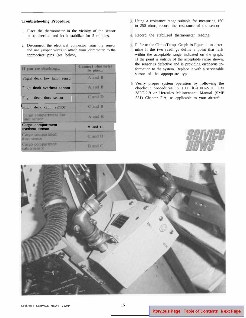
Troubleshooting Procedure:
1. Place the thermometer in the vicinity of the sensorto be checked and let it stabilize for 5 minutes.
2. Disconnect the electrical connector from the sensorand use jumper wires to attach your ohmmeter to theappropriate pins (see below).
t
Flighl deck low limit sensor
Flight deck overheat sensor
Flight deck duct sensor
Flight deck cabin sensor
Cargo compartmentoverheat sensor / A and C
I
Using a resistance range suitable for measuring 160to 250 ohms, record the resistance of the sensor.
Record the stabilized thermometer reading.
Refer to the Ohms/Temp Graph in Figure 1 to deter-mine if the two readings define a point that fallswithin the acceptable range indicated on the graph.If the point is outside of the acceptable range shown,the sensor is defective and is providing erroneous in-formation to the system. Replace it with a serviceablesensor of the appropriate type.
Verify proper system operation by following thecheckout procedures in T.O. lC-130H-2-10, TM382C-2-9 or Hercules Maintenance Manual (SMP581) Chapter 2lA, as applicable to your aircraft.
Lockheed SERVICE NEWS V12N4 15
,,-,~· ;:c: b 0- Ol ., . .... ,;. ·-·~ •u ..
"'
c~'
.