Embed Size (px)
Citation preview

Form 3359 CARTER CARBURETOR CORPORATION. T. LOUIS, MO. U. u. A. 1939 W-O Circuit April. 1939 Service Procedure Reprinted July. 19.39
SERVICE PROCEDURE W-O CARBURETER
A fast, simple, Circuit method of servicing Carter W-O Carbureters. Use Carter Tool Kit. BE ACCURATE.
\. .Jr 7.
Remove choker link pin Remove nozzle passage spring. c h 0 k e r connector plug and gasket assembly. link and spring. nozzle retainer plug and
nozzle.
To remove nozzle, use tool TI09-55.
2. 8.
Remove air horn assembly Remove low speed jet plug with all parts attached. and gasket assembly. and
low speed jet.
3. 9.
Remove throttle shaft arm Remove pump jet passage and screw assembly and plug and gasket assembly. throttle connector rod. and pump jet.
4. 10.
Remove bowl cover with Remove metering rod jet all parts attached. and gasket assembly.
5. n. Disassemble fl an g e fr 0 m
screw and spring. Remove idle adjusting
body and remove insulator and gaskets.
6. 12.
Remove strainer passage gasket assembly. and idle Remove idle well plug and
plug and gasket assembly. well jet. strainer and intake and
discharge ball check assemblies.
Oopyrigh t 1939 hy Oarter Oarhuretor Corpora lion

CARTER CARBURETOR CORPORATION, ST. LOUIS, MO, U. S. A
I) ..-...-11 I...
I'
13.
Remove idle port rivet plug.
Ir
14.
Remove throttle valve screws. throttle valve and throttle shaft and lever assembly.
15.
Remove all parts from horn and dust cover sembly.
air as
16.
Disassemble all parts from bowl cover.
Clean all castings thoroughly, inside and out, with a small brush and clean gasoline. Then blow out all passages with corn· pressed air.
TO REASSEMBLE
17.
Group all parts controlling gasoline level.
18.
Group all idle system parts.
19.
Group all high speed system parts.
20.
Group all pump system parts.
21.
Group all choke system parts.
(See note at boltom o[ page.)
22.
Install bowl cover gasket.
Check bowl cover [or warpage and wear on countershaft pin.
23.
Install needle sea t and gasket in bowl cover.
If needle shows groove on sealing sur f ace. replace both needle and seat.
24.
Install needle in seat. then install float and lever assembly.
Check float for dents and wear on lip, and float pin fOJ wear.
1.,(I:
~ -.ii 0010 .,A I
~ ~
_.~! ~
Sl
Note: Examine each part in each group and replace those parts that shows signs 01 wear or damage. If any carbon is in the bore of the !lange, remove it by scraping, or with sandpaper (do not use emery cloth). Install all parts tight Use all new gaskets.

CARTER CARBURETOR CORPORATION, ST. LOUIS, MO, U. S. A.
25. .J,. Set noat level.
Turn gasket a r 0 u n d so gauge can be placed on machined surface of casting. Adjustment is obtained by bending lip of float which contacts needle. Do not bend front of float as damage will result. When holding bowl cover in normal position, free end of float should have minimum drop of 112". Adjustment is made by bending small float-stop lips at anchored end of lIoat.
26.
Install pump jet and pump jet plug and gasket assembly.
27.
Install discharge and intake ball check assembly. strainer. and strainer plug and gasket assembly.
28.
Install pump spring. and pump plunger and rod assembly.
29.
Install throttle shaft and lever assembly and throttle valve.
After installing lever, back out throttle lever adjusting screw. Then install valve with small "c" toward idle port opening and facing manifold sid e of flange. With valve screws loose, tap throttle valve lightly to cen tralize it in bore of carbureter. Hold valve in place w~th fingers and securely tighten screws. Always use new screws.
30.
Install idle ad; ustm en t screw and spring. Set screw to specifications. t
31.
Assemble flange to body.
Use new gaskets. Lin up holes in body casting with holes in insulator, gaskets and flange before tightening screws. Don't forget lock washers.
32.
Install low speed jet. and low speed jet plug and gasket assembly.
Work jet well inlo seal by moving back and forth to insure a good seaL
33.
Install idle well jet. and idle well plug and gasket assembly.
34.
Install metering rod jet and gasket assembly.
Examine jet and metering rod for wear. If ei,ther shows signs of damage, replace both.
35.
Install bowl cover as assembled.
Use new gasket. Tighten screws evenly and securely.
36.
Install pump arm and collar. and pump operating lever assembly on pin in bowl cover.
CAR·BURErER Trade )lark Be•. U. S. A. '" Canada
CARTER CARBURETOR CORPORATION, ST. LOUIS, MO., U. S. A.
37.
Install pump connedor link.
Ends of lin k should be away from bore with pin spring at top.
38. Install throttle shaft arm and s ere w assembly on throttle shaft. Then install throttle connector rod u sin g new spring and ret a i n e r at lower end and pin spring at top end. Examine throttle connector rod and throttle shaft arm for signs of wear.
39.
Adjust pump stroke.
(See note at bottom of right hand column.)
40.
mustration shows proper method of bending throttle connedor rod for pump adjustment.
41.
Adjust metering rod.
(See note a bottom of right hand column.)
42.
Install noazle. Donie retainer plug. and noaale plug and gasket assembly. Install nozzle with flat side facing up. Use tool Tl09-55.
t
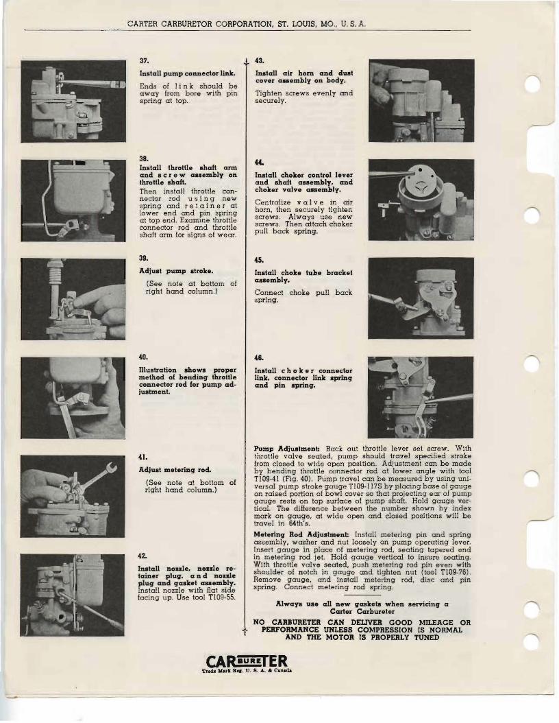
43.
Install air hom and dust cover assembly on body.
Tighten screws evenly and securely.
Install choker control lever and shaft assembly, and choker valve anembly.
Centralize val vein air horn. then securely tighten screws. Always use new screws. Then attach choker pull back spring.
45.
Install choke tube bracket assembly.
Connect choke pull back spring.
46.
Install c h 0 k e r connector link. connector link spring and pin spring.
Pump Adjustment: Back out throttle lever set screw. With throttle valve seated. pump should travel specified stroke from closed to wide open position. Adjustment can be made by bending throttle connector rod at lower angle with tool Tl09-41 (Fig. 40). Pump travel can be measured by using universal pump stroke gauge Tl09-117S by placing base of gauge on raised portion of bowl cover so that projecting ear of pump gauge rests on top surface of pump shaft. Hold gauge vertical. The difference between the number shown by index mark on gauge, at wide open and closed positions will be travel in 64th's.
Metering Rod Adjustment: Install metering pin and spring assembly, washer and nut loosely on pump operating lever. Insert gauge in place of metering rod. seating tapered end in metering rod jet. Hold gauge vertical to insure seating. With throttle valve seated, push metering rod pin even with shoulder of notch in gauge and tighten nut (tool Tl09-76). Remove spring.
gauge, and install metering Connect metering rod spring.
rod. disc and pin
Always us. all new gaskets when seCarter Carbureter
rvicing a
NO CARBURETER CAN DEUVER GOOD MILEAGE OR PERFORMANCE UNLESS COMPRESSION IS NORMAL
AND THE MOTOR IS PROPERLY TUNED
CARaURErER Trade Marl B... U. 8. .L 6; Canada