Embed Size (px)
Citation preview
052540-301r5 Printed in USA February, 2012
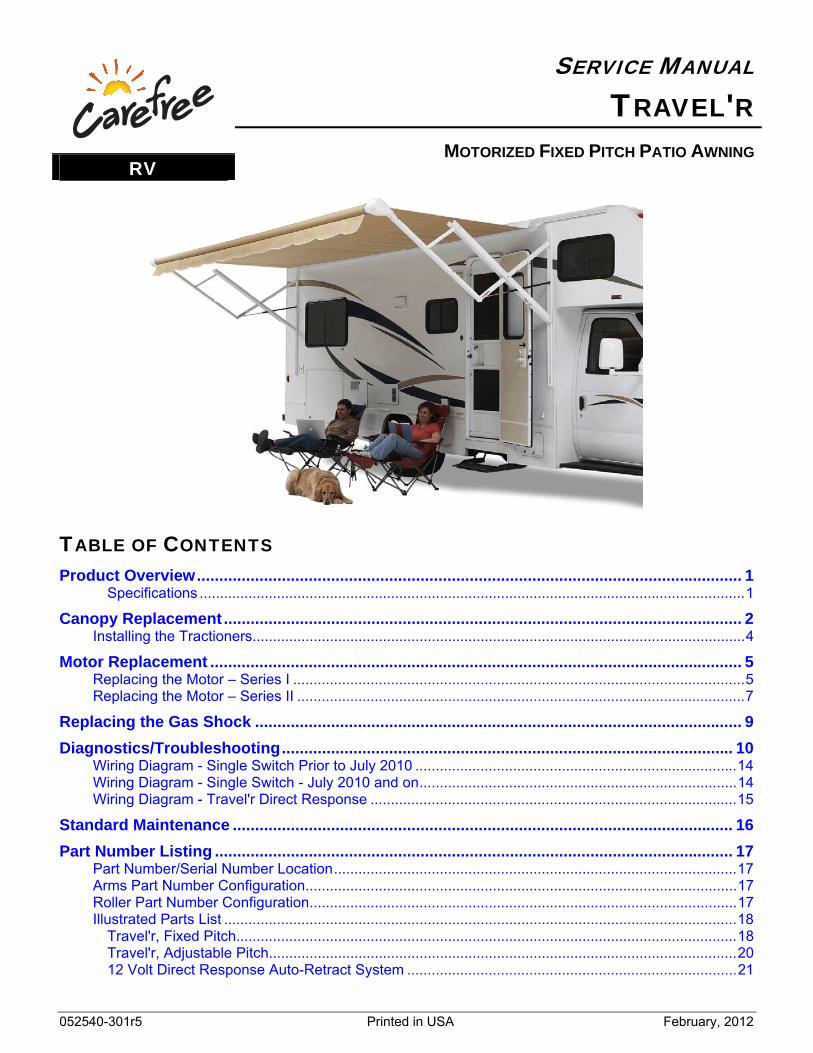
SERVICE MANUAL TRAVEL'R
MOTORIZED FIXED PITCH PATIO AWNINGRV
TABLE OF CONTENTS Product Overview .......................................................................................................................... 1
Specifications ...................................................................................................................................... 1
Canopy Replacement .................................................................................................................... 2 Installing the Tractioners ......................................................................................................................... 4
Motor Replacement ....................................................................................................................... 5 Replacing the Motor – Series I ............................................................................................................... 5 Replacing the Motor – Series II .............................................................................................................. 7
Replacing the Gas Shock ............................................................................................................. 9
Diagnostics/Troubleshooting ..................................................................................................... 10 Wiring Diagram - Single Switch Prior to July 2010 ............................................................................... 14 Wiring Diagram - Single Switch - July 2010 and on .............................................................................. 14 Wiring Diagram - Travel'r Direct Response .......................................................................................... 15
Standard Maintenance ................................................................................................................ 16
Part Number Listing .................................................................................................................... 17 Part Number/Serial Number Location ................................................................................................... 17 Arms Part Number Configuration .......................................................................................................... 17 Roller Part Number Configuration ......................................................................................................... 17 Illustrated Parts List .............................................................................................................................. 18
Travel'r, Fixed Pitch........................................................................................................................... 18 Travel'r, Adjustable Pitch................................................................................................................... 20 12 Volt Direct Response Auto-Retract System ................................................................................. 21
PROPRIETARY STATEMENT The Travel'r Patio Awning is a product of Carefree of Colorado, located in Broomfield, Colorado, USA. The information contained in or disclosed in this document is considered proprietary to Carefree of Colorado. Every effort has been made to ensure that the information presented in the document is accurate and complete. However, Carefree of Colorado assumes no liability for errors or for any damages that result from the use of this document.
The information contained in this manual pertains to the current configuration of the models listed on the title page. Earlier model configurations may differ from the information given. Carefree of Colorado reserves the right to cancel, change, alter or add any parts and assemblies, described in this manual, without prior notice.
Carefree of Colorado agrees to allow the reproduction of this document for use with Carefree of Colorado products only. Any other reproduction or translation of this document in whole or part is strictly prohibited without prior written approval from Carefree of Colorado.
SAFETY INFORMATION
WARNING A WARNING INDICATES A POTENTIALLY HAZARDOUS SITUATION WHICH, IF NOT AVOIDED, COULD RESULT IN
DEATH OR SERIOUS INJURY AND/OR MAJOR PROPERTY DAMAGE.
CAUTION A CAUTION INDICATES A POTENTIALLY HAZARDOUS SITUATION THAT MAY CAUSE MINOR TO MODERATE
PERSONAL INJURY AND/OR PROPERTY DAMAGE. IT MAY ALSO BE USED TO ALERT AGAINST UNSAFE PRACTICES.
NOTE: A note indicates further information about a product, part, or step.
Tip: A tip provides helpful suggestions.
Safety Notes: Always disconnect battery or power source before working on or around the electrical system.
Always wear appropriate safety equipment (i.e. goggles).
Always use appropriate lifting devices and/or helpers when lifting or holding heavy objects.
When using fasteners, use care to not over tighten. Soft materials such as fiberglass and aluminum can be "stripped out" and lose the ability to grip and hold.
Reference Publications located @ www.carefreeofcolorado.com:' 052540-002 Travel'r, Installation Manual
052540-201 Travel'r, Owner's Manual
052540-301 Travel'r, Service Manual
Carefree of Colorado 2145 W. 6th Avenue Broomfield, CO 80020 a Scott Fetzer company 303-469-3324 ♦ www.carefreeofcolorado.com
Carefree of Colorado Service Manual TRAVEL'R
052540-301r5 1
PRODUCT OVERVIEW The Travel'r provides motorized awning comfort with Carefree's standards for looks, strength and dependability. It is the successful blend of style, quality and economy.
The unique "scissor" style arms provide maximum strength, stability and ease of operation.
Worm gear style motor is billow proof - eliminates the need for travel locks.
Available in 3 styles: Fixed Flat Pitch Fixed Steep Pitch Adjustable Pitch
For the fixed flat pitch and the adjustable set to the flat pitch, the auto-dump feature automatically releases to allow water to run-off to prevent water pooling. When the water is gone, the arms return to the fully extended position.
The Adjustable Pitch Travel'r has easy to use 6-position pitch adjustment. The pitch can be left in any position and the awning will roll up completely! When the awning is rolled back out, it rolls out to the pitch setting previously set.
Can be installed using a single switch control or with the Direct ResponseTM electronic system.
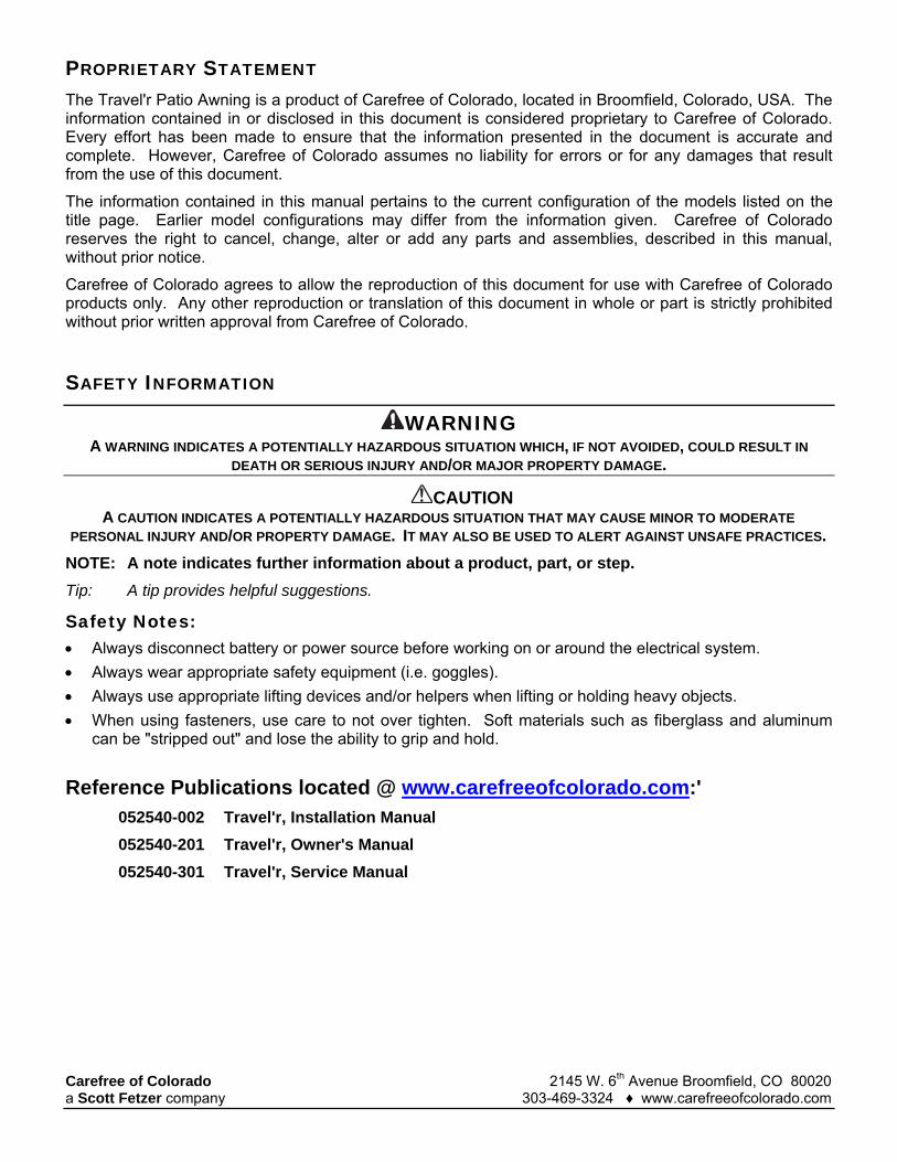
Specifications LENGTH 12' - 21' [366 - 640cm]
EXTENSION: 8' [244cm] Drop @ Flat Pitch: 12" [30.5cm] Drop @ Steep Pitch: 36" [91cm] Values are approximate, actual dimensions may vary with specific installations.
EXTENSION TIME: 28 Seconds (approx) RETRACT TIME: 32 Seconds (approx)
POWER REQUIREMENTS: 12VDC (operating range 10VDC to 14VDC) Circuit Rating: 15 amp
POWER SOURCE: Motor and controls are routed and hardwired into the vehicle’s 12V system
EMERGENCY RETRACT: Electrical override system (external power source)
COLOR: Hardware: White or Black
Fabric: Vinyl, Polyweave or Acrylic Fabric with Alumaguard or Uniguard
Fabric Wrap: Weatherguard (vinyl) or Metal Wraps: Alumaguard or Uniguard
OPTIONS: Direct Response Electronic Package available as an upgrade kit
Available as a complete awning or as an upgrade to existing Carefree or A&E awnings with an 8’ extension. If upgrading an A&E with a steel roller tube it is also necessary to replace the roller tube with a Carefree aluminum roller tube.
An optional Rail Extension Kit available for Mesa & Yoder sidewalls.
90oTyp.
Centerlineof Arm
Centerlineof Arm
Awning Length
TravelR003pc
Fabric Width5”(approx)
5”(approx)
Awning Rail
= Flat Mounting Surface AreaFlat Pitch & Adjustable 3 1/2” x 67”Steep Pitch 3 1/2” x 59 1/2”
Centerlineof Arm
Detail A(Fixed Steep Pitch)
( Fixed Flat Pitch &Adjustable Pitch)
6”Clearancefrom top of
door 14.5”Clearancefrom top of
door
6”(approx)
Figure 1. General Layout.
TRAVEL'R Service Manual Carefree of Colorado
2 052540-301r5
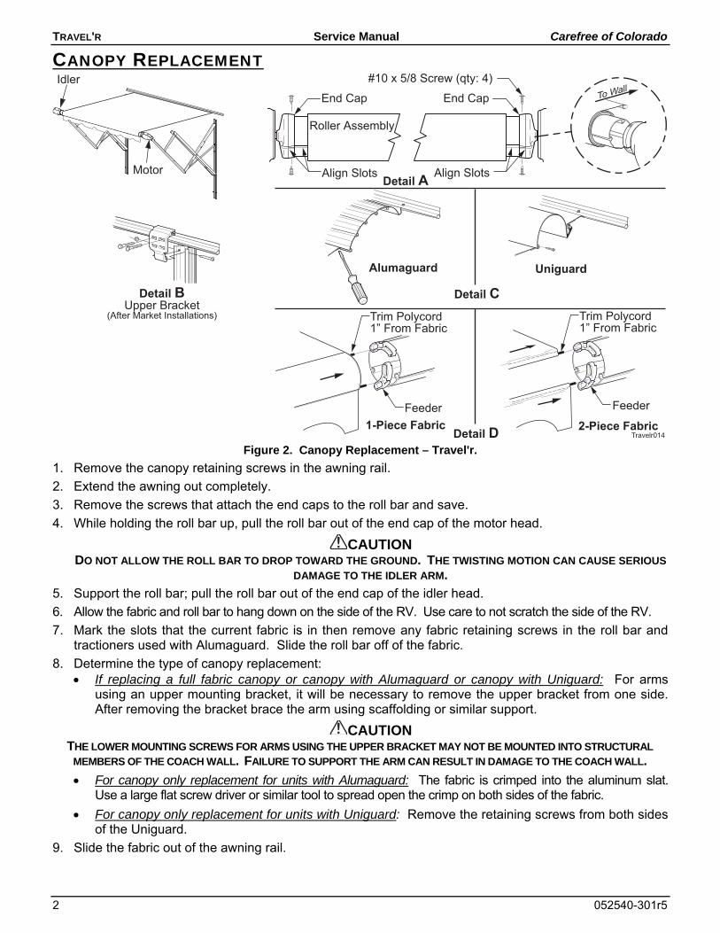
CANOPY REPLACEMENT
Feeder Feeder
Trim Polycord1” From Fabric
Trim Polycord1” From Fabric
1-Piece Fabric 2-Piece Fabric
Idler
Motor
Travelr014
Roller Assembly
Align Slots
End Cap
#10 x 5/8 Screw (qty: 4)
End Cap
Align SlotsDetail A
Detail BUpper Bracket
(After Market Installations)
Alumaguard Uniguard
Detail C
Detail D Figure 2. Canopy Replacement – Travel'r.
1. Remove the canopy retaining screws in the awning rail.
2. Extend the awning out completely.
3. Remove the screws that attach the end caps to the roll bar and save.
4. While holding the roll bar up, pull the roll bar out of the end cap of the motor head.
CAUTION DO NOT ALLOW THE ROLL BAR TO DROP TOWARD THE GROUND. THE TWISTING MOTION CAN CAUSE SERIOUS
DAMAGE TO THE IDLER ARM.
5. Support the roll bar; pull the roll bar out of the end cap of the idler head.
6. Allow the fabric and roll bar to hang down on the side of the RV. Use care to not scratch the side of the RV.
7. Mark the slots that the current fabric is in then remove any fabric retaining screws in the roll bar and tractioners used with Alumaguard. Slide the roll bar off of the fabric.
8. Determine the type of canopy replacement: If replacing a full fabric canopy or canopy with Alumaguard or canopy with Uniguard: For arms
using an upper mounting bracket, it will be necessary to remove the upper bracket from one side. After removing the bracket brace the arm using scaffolding or similar support.
CAUTION THE LOWER MOUNTING SCREWS FOR ARMS USING THE UPPER BRACKET MAY NOT BE MOUNTED INTO STRUCTURAL
MEMBERS OF THE COACH WALL. FAILURE TO SUPPORT THE ARM CAN RESULT IN DAMAGE TO THE COACH WALL.
For canopy only replacement for units with Alumaguard: The fabric is crimped into the aluminum slat. Use a large flat screw driver or similar tool to spread open the crimp on both sides of the fabric.
For canopy only replacement for units with Uniguard: Remove the retaining screws from both sides of the Uniguard.
9. Slide the fabric out of the awning rail.
Carefree of Colorado Service Manual TRAVEL'R
052540-301r5 3
10. Clean and deburr the roll bar slots and awning rail/Alumaguard/Uniguard as required. If not previously done, spread open the awning rail track to facilitate inserting the new fabric.
Tip: Lightly spraying the slots with a dry silicone lubricant will help the fabric slide into the slot without staining the material.
11. Unfold the replacement fabric then slide the new fabric into the awning rail/Alumaguard/Uniguard. Center the fabric and install any fabric retaining screws removed previously. Allow the fabric to hang down the side of the coach.
For Alumaguard installations: Use a pair of side cutters or similar tool and crimp the aluminum. Use care to not bend or distort the aluminum slats.
NOTE: While the awning fabric is fairly robust, care must be taken not to snag it on the awning rail.
12. Position the fabric feeders on the roll bar. Be sure to use the same slots as the old canopy.
13. Slide the rollbar on to the new fabric. Center the fabric and install any fabric retaining screws removed previously.
14. Remove the feeders.
15. If removed, install the upper mounting bracket.
16. Lift and align the roller assembly with the end cap on the motorized arm assembly. Rotate the end cap until the slot in the cap aligns with the empty slot in the roller assembly, and then press the roller assembly fully into the cap. The end cap must seat squarely over the end of the roller assembly when complete.
NOTE: The roller assembly must be oriented with the fabric going over the roller toward the coach wall.
17. Secure the end cap to the roll bar using two #10 square-drive screws.
18. Repeat steps 17 and 18 to attach the idler arm assembly to the roll bar.
19. Visually check that the fabric is squarely mounted. Adjust as required.
20. Roll the awning in and out several times to make sure that the fabric is square on the rollbar.
21. Secure the canopy to the awning rail using one, #6 x 3/8" hex head screw at both sides of the awning.
Fabric Alumaguard
1"
#6 x 3/8Screw
Polyrod
E0014Fabric
1"
#6 x 3/8Screw
#6 x 3/8Screw
Awning RailAwning RailAwning Rail Polyrod
Uniguard
Soft Connect
Figure 3. Securing the Fabric.
21.1. For vinyl awnings, place screw through awning rail, polyrod and canopy approximately 1” in from the end of the fabric.
21.2. For Uniguard awnings, place screw through awning rail, polyrod and the soft connect material approximately 1" in from the end of the fabric.
21.3. For Alumaguard awnings, place screw on the outer edge of the Alumaguard (not through the Alumaguard).
For Alumaguard installations, go to "Installing the Tractioners" on page 4.
TRAVEL'R Service Manual Carefree of Colorado
4 052540-301r5
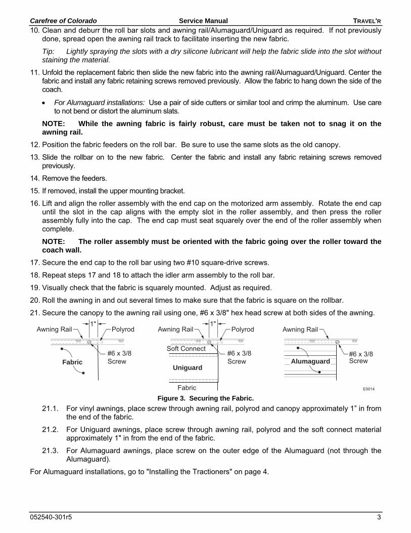
INSTALLING THE TRACTIONERS The tractioners are used with the alumaguard metal fabric wrap and recommended for vinyl fabrics with Uniguard.
1/4" Gap
A
A
View A-A(Uniguard w/ Vinyl Fabric)
Position Tractioner underAlumaguard/Uniguard
Keeper
E0058
1/4" Gap
Alumaguard orUniguard
View A-A(Alumaguard)
Place ScrewBetween Slotson Roller
Place ScrewBetween Slotson Roller
Figure 4. Installing the Tractioner.
1. Partially extend the awning until the Alumaguard/Uniguard is extended as shown.
2. Unlock the keeper and wrap the tractioner around the roller tube.
3. Position the tractioner under the Alumaguard/Uniguard with a 1/4” gap between Alumaguard and tractioner. Lock the keeper.
4. Repeat for the other end of the rollbar.
5. Extend the awning to verify that the tractioners are lifting the metal wrap up and over the roller assembly.
6. To secure the tractioner, drill a 1/8” hole through the tractioner and rollbar, roughly center the hole between two slots of the rollbar.
7. Secure with one (1) #10 square drive screw.
Carefree of Colorado Service Manual TRAVEL'R
052540-301r5 5
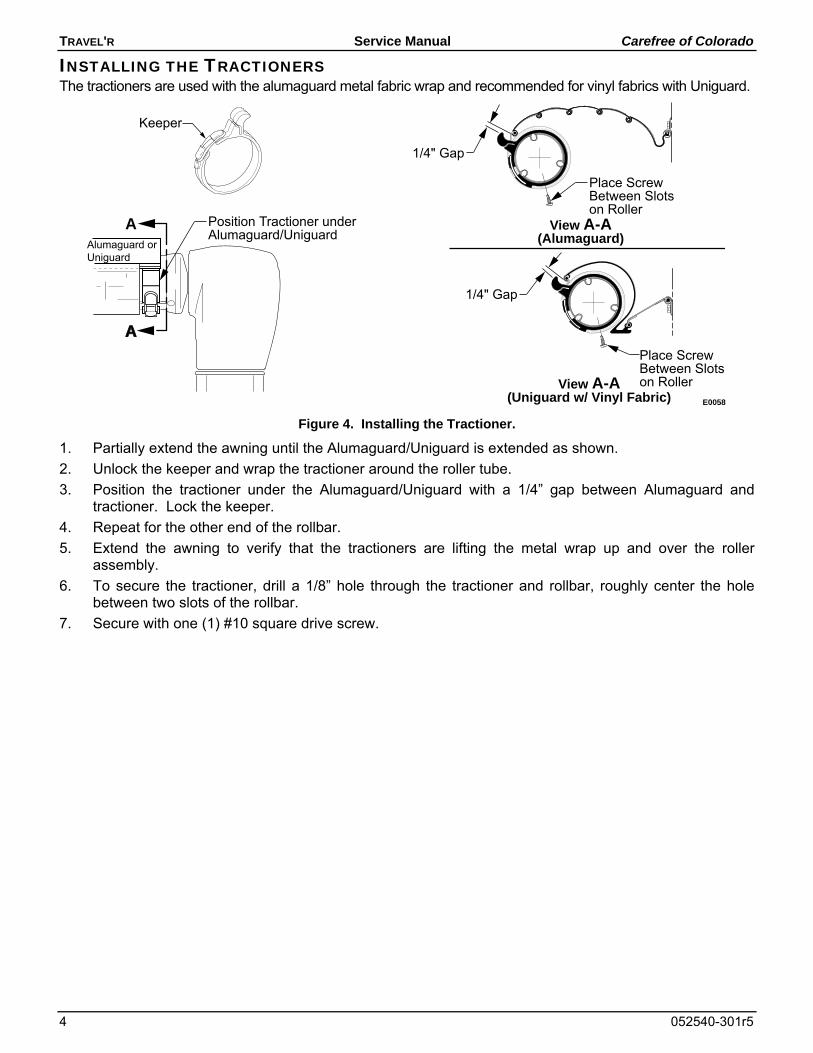
MOTOR REPLACEMENT STOP! Before continuing, it is necessary to determine which motor configuration is installed on the awning. SERIES I uses a bent sheet metal mounting frame. SERIES II uses a cast metal mounting frame. The mounting and attachment of the two configurations are different. To distinguish between the two, look at the motor head. The bent sheet metal frame (Series I) has two protruding bumps in the front cover. There are also two exposed rivets on each side of the arm channel. The cover for the cast metal (Series II) is smooth and there are no rivets.
NOTE: Motor assemblies and covers are not interchangeable between the two configurations.
REPLACING THE MOTOR – SERIES I
Spacers(qty: 11)
3/8-16 x 6 Bolt
Front Cover
Rear Cover
3/8-16Lock Nut
Travelr015
Motor
End Cap
#10 x 5/8 Screw
DETAIL D
DETAIL AMotor - Red WireCable - Red Wire
Motor - Black WireCable - Black Wire
DETAIL C
Motor (ref)
Motor AttachBolts & Nuts
Rear Cover(ref)
Front Cover(ref)
DETAIL B
Motor AssemblyW/ Bent Metal
Frame
Figure 6. Motor Replacement – Series I.
1. (refer to Detail A) For Awnings Fully or Partially Extended:
1.1 On the right hand arm remove the front cover by removing the six (6) smaller screws from the back of the motor head. Save cover and screws.
1.2 Disconnect the motor and cable wires from inside the rear cover. Note the location of each wire.
1.3 Remove the rear cover by removing the one (1) large screw from the back of the motor head. Save cover and screw.
1.4 Go to step 3.
Travelr016
Configuration ABent Sheetmetal
Motor Mount Frame
Configuration BCast Metal
Motor Mount Frame
ExternalRivets
ProtrudingBumps in
Front Cover
Figure 5. Distinguishing the Motor Mount.
TRAVEL'R Service Manual Carefree of Colorado
6 052540-301r5
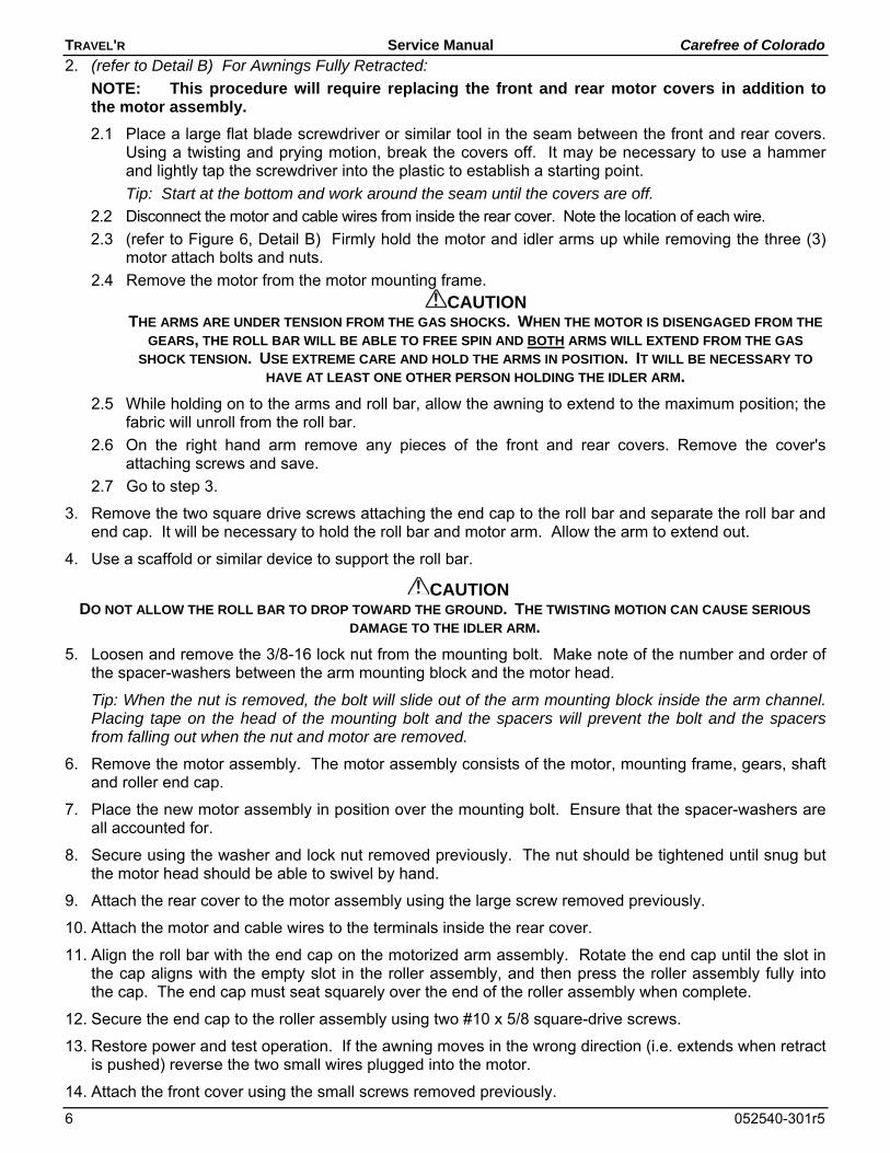
2. (refer to Detail B) For Awnings Fully Retracted:
NOTE: This procedure will require replacing the front and rear motor covers in addition to the motor assembly.
2.1 Place a large flat blade screwdriver or similar tool in the seam between the front and rear covers. Using a twisting and prying motion, break the covers off. It may be necessary to use a hammer and lightly tap the screwdriver into the plastic to establish a starting point.
Tip: Start at the bottom and work around the seam until the covers are off.
2.2 Disconnect the motor and cable wires from inside the rear cover. Note the location of each wire.
2.3 (refer to Figure 6, Detail B) Firmly hold the motor and idler arms up while removing the three (3) motor attach bolts and nuts.
2.4 Remove the motor from the motor mounting frame.
CAUTION THE ARMS ARE UNDER TENSION FROM THE GAS SHOCKS. WHEN THE MOTOR IS DISENGAGED FROM THE
GEARS, THE ROLL BAR WILL BE ABLE TO FREE SPIN AND BOTH ARMS WILL EXTEND FROM THE GAS
SHOCK TENSION. USE EXTREME CARE AND HOLD THE ARMS IN POSITION. IT WILL BE NECESSARY TO
HAVE AT LEAST ONE OTHER PERSON HOLDING THE IDLER ARM.
2.5 While holding on to the arms and roll bar, allow the awning to extend to the maximum position; the fabric will unroll from the roll bar.
2.6 On the right hand arm remove any pieces of the front and rear covers. Remove the cover's attaching screws and save.
2.7 Go to step 3.
3. Remove the two square drive screws attaching the end cap to the roll bar and separate the roll bar and end cap. It will be necessary to hold the roll bar and motor arm. Allow the arm to extend out.
4. Use a scaffold or similar device to support the roll bar.
CAUTION DO NOT ALLOW THE ROLL BAR TO DROP TOWARD THE GROUND. THE TWISTING MOTION CAN CAUSE SERIOUS
DAMAGE TO THE IDLER ARM.
5. Loosen and remove the 3/8-16 lock nut from the mounting bolt. Make note of the number and order of the spacer-washers between the arm mounting block and the motor head.
Tip: When the nut is removed, the bolt will slide out of the arm mounting block inside the arm channel. Placing tape on the head of the mounting bolt and the spacers will prevent the bolt and the spacers from falling out when the nut and motor are removed.
6. Remove the motor assembly. The motor assembly consists of the motor, mounting frame, gears, shaft and roller end cap.
7. Place the new motor assembly in position over the mounting bolt. Ensure that the spacer-washers are all accounted for.
8. Secure using the washer and lock nut removed previously. The nut should be tightened until snug but the motor head should be able to swivel by hand.
9. Attach the rear cover to the motor assembly using the large screw removed previously.
10. Attach the motor and cable wires to the terminals inside the rear cover.
11. Align the roll bar with the end cap on the motorized arm assembly. Rotate the end cap until the slot in the cap aligns with the empty slot in the roller assembly, and then press the roller assembly fully into the cap. The end cap must seat squarely over the end of the roller assembly when complete.
12. Secure the end cap to the roller assembly using two #10 x 5/8 square-drive screws.
13. Restore power and test operation. If the awning moves in the wrong direction (i.e. extends when retract is pushed) reverse the two small wires plugged into the motor.
14. Attach the front cover using the small screws removed previously.
Carefree of Colorado Service Manual TRAVEL'R
052540-301r5 7
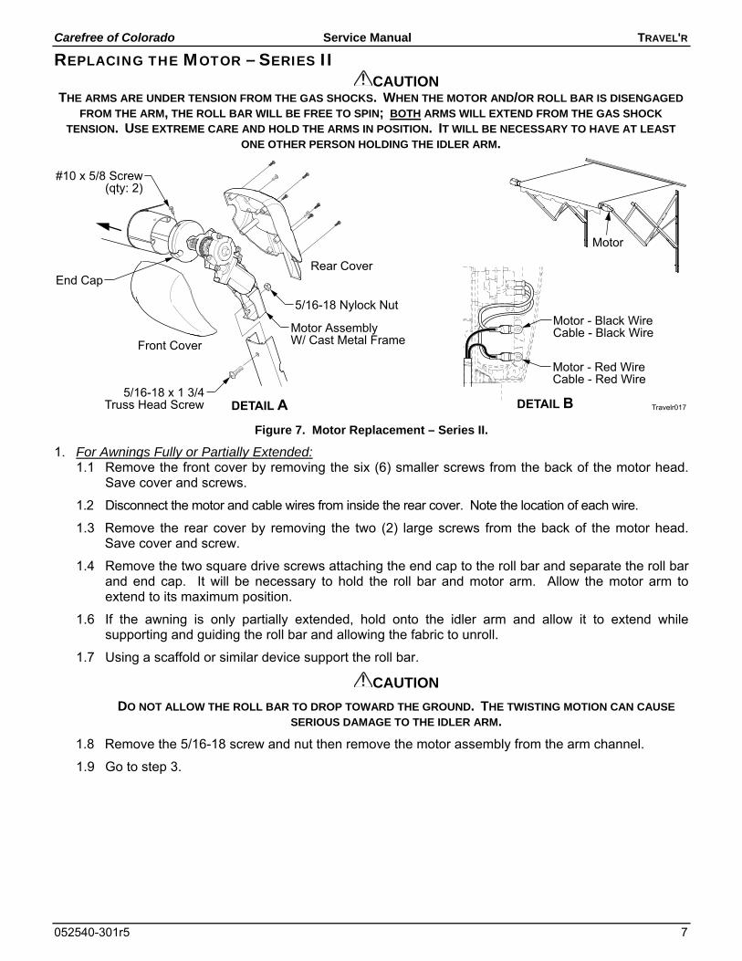
REPLACING THE MOTOR – SERIES II CAUTION
THE ARMS ARE UNDER TENSION FROM THE GAS SHOCKS. WHEN THE MOTOR AND/OR ROLL BAR IS DISENGAGED
FROM THE ARM, THE ROLL BAR WILL BE FREE TO SPIN; BOTH ARMS WILL EXTEND FROM THE GAS SHOCK
TENSION. USE EXTREME CARE AND HOLD THE ARMS IN POSITION. IT WILL BE NECESSARY TO HAVE AT LEAST
ONE OTHER PERSON HOLDING THE IDLER ARM.
Motor - Red WireCable - Red Wire
Motor - Black WireCable - Black Wire
DETAIL B
Front Cover
Rear Cover
Travelr017
Motor
End Cap
DETAIL A5/16-18 x 1 3/4
Truss Head Screw
#10 x 5/8 Screw(qty: 2)
5/16-18 Nylock Nut
Motor AssemblyW/ Cast Metal Frame
Figure 7. Motor Replacement – Series II.
1. For Awnings Fully or Partially Extended: 1.1 Remove the front cover by removing the six (6) smaller screws from the back of the motor head.
Save cover and screws.
1.2 Disconnect the motor and cable wires from inside the rear cover. Note the location of each wire.
1.3 Remove the rear cover by removing the two (2) large screws from the back of the motor head. Save cover and screw.
1.4 Remove the two square drive screws attaching the end cap to the roll bar and separate the roll bar and end cap. It will be necessary to hold the roll bar and motor arm. Allow the motor arm to extend to its maximum position.
1.6 If the awning is only partially extended, hold onto the idler arm and allow it to extend while supporting and guiding the roll bar and allowing the fabric to unroll.
1.7 Using a scaffold or similar device support the roll bar.
CAUTION
DO NOT ALLOW THE ROLL BAR TO DROP TOWARD THE GROUND. THE TWISTING MOTION CAN CAUSE
SERIOUS DAMAGE TO THE IDLER ARM.
1.8 Remove the 5/16-18 screw and nut then remove the motor assembly from the arm channel.
1.9 Go to step 3.
TRAVEL'R Service Manual Carefree of Colorado
8 052540-301r5
2. For Awnings Fully Retracted: 2.1 While holding both arms and the rollbar, remove the 5/16-18 screw. Allow the motor arm to extend
out and away from the motor assembly and rollbar.
2.2 Tie the idler arm in the closed or partially open position.
2.3 Using a scaffold or similar device support the roll bar.
2.4 Rotate the rollbar and motor head around to access the cover screws on the back
2.5 Remove the front cover by removing the six (6) smaller screws from the back of the motor head. Save cover and screws.
2.6 Disconnect the motor and cable wires from inside the rear cover. Note the location of each wire.
2.7 Remove the rear cover by removing the two (2) large screws from the back of the motor head. Save cover and screws.
2.8 Remove the two square drive screws attaching the end cap to the roll bar and separate the roll bar and end cap.
3. Position the new motor assembly in the arm channel and attach using one each 5/16-18 x 1 1/2 bolt and nylock nut.
4. Attach the rear cover to the motor assembly using the large screws removed previously.
5. Attach the motor and cable wires to the terminals inside the rear cover.
6. Align the roll bar with the end cap on the motorized arm assembly. Rotate the end cap until the slot in the cap aligns with the empty slot in the roller assembly, and then press the roller assembly fully into the cap. The end cap must seat squarely over the end of the roller assembly when complete.
NOTE: It may be necessary to close and hold the arm to align the end cap and roll bar.
7. Secure the end cap to the roller assembly using two #10 x 5/8 square-drive screws.
8. Restore power and test operation. If the awning moves in the wrong direction (i.e. extends when retract is pushed) reverse only the two motor wires in the rear cover.
9. Attach the front cover using the small screws removed previously.
Carefree of Colorado Service Manual TRAVEL'R
052540-301r5 9
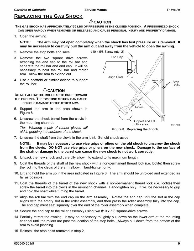
REPLACING THE GAS SHOCK CAUTION
THE GAS SHOCK HAS APPROXIMATELY 85 LBS OF PRESSURE IN THE CLOSED POSITION. A PRESSURIZED SHOCK
CAN OPEN RAPIDLY WHEN REMOVED OR RELEASED AND CAUSE PERSONAL INJURY AND PROPERTY DAMAGE.
1. Open the awning.
NOTE: The arm may not open completely when the shock has lost pressure or is removed. It may be necessary to carefully pull the arm out and away from the vehicle to open the awning.
2. Remove the stop bolts and save.
3. Remove the two square drive screws attaching the end cap to the roll bar and separate the roll bar and end cap. It will be necessary to hold the roll bar and motor arm. Allow the arm to extend out.
4. Use a scaffold or similar device to support the roll bar.
CAUTION DO NOT ALLOW THE ROLL BAR TO DROP TOWARD
THE GROUND. THE TWISTING MOTION CAN CAUSE
SERIOUS DAMAGE TO THE OTHER ARM.
5. Support the arm in the area shown in Figure 8.
6. Unscrew the shock barrel from the clevis in the mounting channel.
Tip: Wearing a pair of rubber gloves will aid in gripping the surfaces of the shock.
7. Unscrew the shaft from the clevis in the arm joint. Set old shock aside.
NOTE: It may be necessary to use vice grips or pliers on the old shock to unscrew the shock from the clevis. DO NOT use vice grips or pliers on the new shock. Damage to the surface of the shaft or damage to the barrel can cause the new shock to not work correctly.
8. Unpack the new shock and carefully allow it to extend to its maximum length.
9. Coat the threads of the shaft of the new shock with a non-permanent thread lock (i.e. loctite) then screw the rod into the clevis of the arm elbow. Hand-tighten only.
10. Lift and hold the arm up in the area indicated in Figure 8. The arm should be unfolded and extended as far as possible.
11. Coat the threads of the barrel of the new shock with a non-permanent thread lock (i.e. loctite) then screw the barrel into the clevis in the mounting channel. Hand-tighten only. It will be necessary to grip and hold the shaft while turning the barrel.
12. Align the roll bar with the end cap on the arm assembly. Rotate the end cap until the slot in the cap aligns with the empty slot in the roller assembly, and then press the roller assembly fully into the cap. The end cap must seat squarely over the end of the roller assembly when complete.
13. Secure the end cap to the roller assembly using two #10 x 5/8 square-drive screws.
14. Partially retract the awning. It may be necessary to lightly pull down on the lower arm at the mounting channel until the rollers are past the location of the stop bolts. Always pull down from the bottom of the arm to avoid pinching.
15. Reinstall the stop bolts removed in step 2.
Travelr018
Loosen
Loosen
StopBolts
Support and Liftin this area
Align Slots
End Cap
#10 x 5/8 Screw (qty: 2)
Figure 8. Replacing the Shock.
TRAVEL'R Service Manual Carefree of Colorado
10 052540-301r5
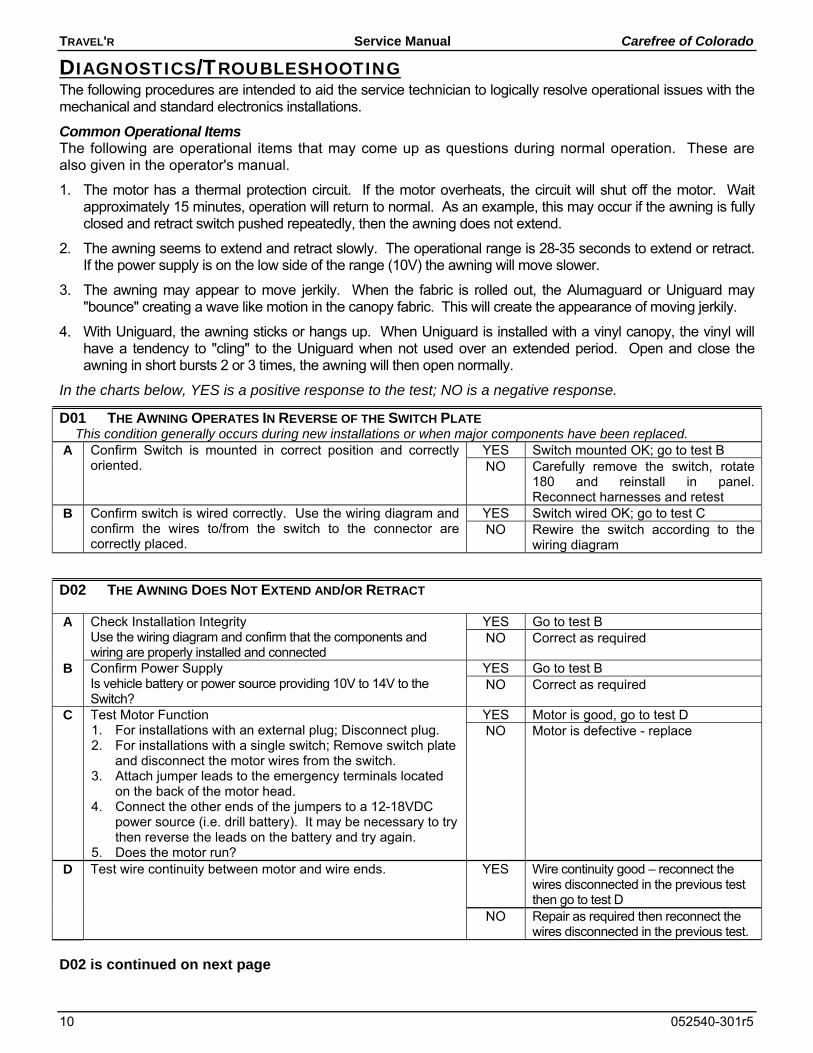
DIAGNOSTICS/TROUBLESHOOTING The following procedures are intended to aid the service technician to logically resolve operational issues with the mechanical and standard electronics installations.
Common Operational Items The following are operational items that may come up as questions during normal operation. These are also given in the operator's manual.
1. The motor has a thermal protection circuit. If the motor overheats, the circuit will shut off the motor. Wait approximately 15 minutes, operation will return to normal. As an example, this may occur if the awning is fully closed and retract switch pushed repeatedly, then the awning does not extend.
2. The awning seems to extend and retract slowly. The operational range is 28-35 seconds to extend or retract. If the power supply is on the low side of the range (10V) the awning will move slower.
3. The awning may appear to move jerkily. When the fabric is rolled out, the Alumaguard or Uniguard may "bounce" creating a wave like motion in the canopy fabric. This will create the appearance of moving jerkily.
4. With Uniguard, the awning sticks or hangs up. When Uniguard is installed with a vinyl canopy, the vinyl will have a tendency to "cling" to the Uniguard when not used over an extended period. Open and close the awning in short bursts 2 or 3 times, the awning will then open normally.
In the charts below, YES is a positive response to the test; NO is a negative response.
D01 THE AWNING OPERATES IN REVERSE OF THE SWITCH PLATE This condition generally occurs during new installations or when major components have been replaced.
A Confirm Switch is mounted in correct position and correctly oriented.
YES Switch mounted OK; go to test B NO Carefully remove the switch, rotate
180 and reinstall in panel. Reconnect harnesses and retest
B Confirm switch is wired correctly. Use the wiring diagram and confirm the wires to/from the switch to the connector are correctly placed.
YES Switch wired OK; go to test C NO Rewire the switch according to the
wiring diagram
D02 THE AWNING DOES NOT EXTEND AND/OR RETRACT
A Check Installation Integrity Use the wiring diagram and confirm that the components and wiring are properly installed and connected
YES Go to test B NO Correct as required
B Confirm Power Supply Is vehicle battery or power source providing 10V to 14V to the Switch?
YES Go to test B NO Correct as required
C Test Motor Function 1. For installations with an external plug; Disconnect plug. 2. For installations with a single switch; Remove switch plate
and disconnect the motor wires from the switch. 3. Attach jumper leads to the emergency terminals located
on the back of the motor head. 4. Connect the other ends of the jumpers to a 12-18VDC
power source (i.e. drill battery). It may be necessary to try then reverse the leads on the battery and try again.
5. Does the motor run?
YES Motor is good, go to test D NO Motor is defective - replace
D Test wire continuity between motor and wire ends. YES Wire continuity good – reconnect the wires disconnected in the previous test then go to test D
NO Repair as required then reconnect the wires disconnected in the previous test.
D02 is continued on next page
Carefree of Colorado Service Manual TRAVEL'R
052540-301r5 11
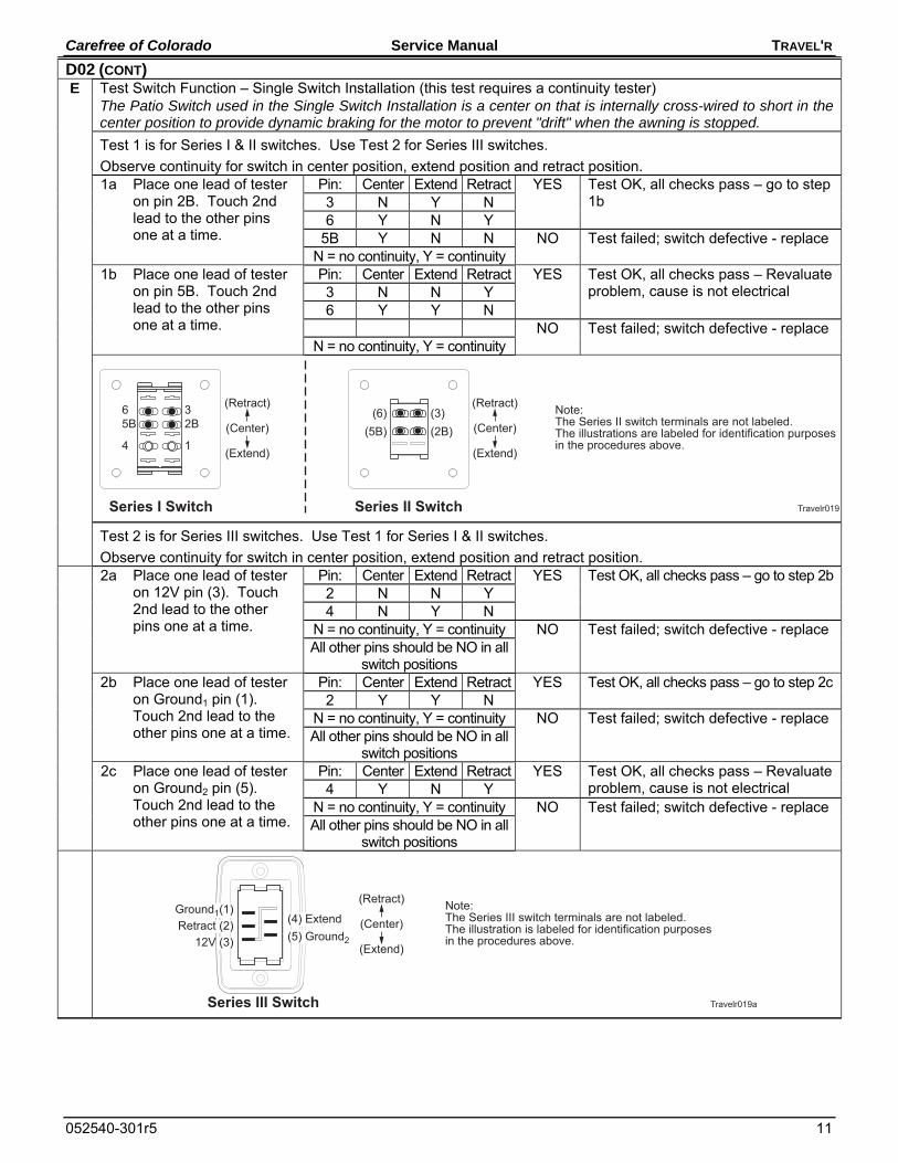
D02 (CONT) E Test Switch Function – Single Switch Installation (this test requires a continuity tester)
The Patio Switch used in the Single Switch Installation is a center on that is internally cross-wired to short in the center position to provide dynamic braking for the motor to prevent "drift" when the awning is stopped.
Test 1 is for Series I & II switches. Use Test 2 for Series III switches.
Observe continuity for switch in center position, extend position and retract position. 1a Place one lead of tester
on pin 2B. Touch 2nd lead to the other pins one at a time.
Pin: Center Extend Retract YES Test OK, all checks pass – go to step 1b 3 N Y N
6 Y N Y 5B Y N N NO Test failed; switch defective - replace
N = no continuity, Y = continuity 1b Place one lead of tester
on pin 5B. Touch 2nd lead to the other pins one at a time.
Pin: Center Extend Retract YES Test OK, all checks pass – Revaluate problem, cause is not electrical 3 N N Y
6 Y Y N NO Test failed; switch defective - replace
N = no continuity, Y = continuity
Travelr019
Note:The Series II switch terminals are not labeled.The illustrations are labeled for identification purposesin the procedures above.
Series I Switch
(Retract)
(Extend)
(Center)65B
4
32B
1
Series II Switch
(Retract)
(Extend)
(Center)(6)
(5B)(3)(2B)
Test 2 is for Series III switches. Use Test 1 for Series I & II switches.
Observe continuity for switch in center position, extend position and retract position. 2a Place one lead of tester
on 12V pin (3). Touch 2nd lead to the other pins one at a time.
Pin: Center Extend Retract YES Test OK, all checks pass – go to step 2b2 N N Y 4 N Y N
N = no continuity, Y = continuity NO Test failed; switch defective - replace All other pins should be NO in all
switch positions 2b Place one lead of tester
on Ground1 pin (1). Touch 2nd lead to the other pins one at a time.
Pin: Center Extend Retract YES Test OK, all checks pass – go to step 2c 2 Y Y N
N = no continuity, Y = continuity NO Test failed; switch defective - replace All other pins should be NO in all
switch positions 2c Place one lead of tester
on Ground2 pin (5). Touch 2nd lead to the other pins one at a time.
Pin: Center Extend Retract YES Test OK, all checks pass – Revaluate problem, cause is not electrical 4 Y N Y
N = no continuity, Y = continuity NO Test failed; switch defective - replace All other pins should be NO in all
switch positions
Travelr019a
Note:The Series III switch terminals are not labeled.The illustration is labeled for identification purposesin the procedures above.
(Retract)
(Extend)
(Center)Ground1(1)
12V (3)Retract (2)
(5) Ground2
(4) Extend
Series III Switch
TRAVEL'R Service Manual Carefree of Colorado
12 052540-301r5
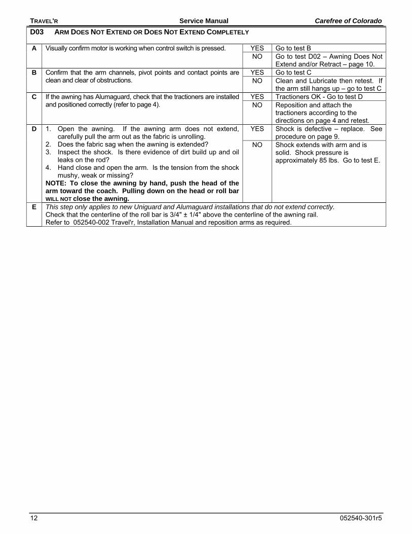
D03 ARM DOES NOT EXTEND OR DOES NOT EXTEND COMPLETELY
A Visually confirm motor is working when control switch is pressed. YES Go to test B NO Go to test D02 – Awning Does Not
Extend and/or Retract – page 10. B Confirm that the arm channels, pivot points and contact points are
clean and clear of obstructions. YES Go to test C NO Clean and Lubricate then retest. If
the arm still hangs up – go to test C C If the awning has Alumaguard, check that the tractioners are installed
and positioned correctly (refer to page 4). YES Tractioners OK - Go to test D NO Reposition and attach the
tractioners according to the directions on page 4 and retest.
D 1. Open the awning. If the awning arm does not extend, carefully pull the arm out as the fabric is unrolling.
2. Does the fabric sag when the awning is extended? 3. Inspect the shock. Is there evidence of dirt build up and oil
leaks on the rod? 4. Hand close and open the arm. Is the tension from the shock
mushy, weak or missing? NOTE: To close the awning by hand, push the head of the arm toward the coach. Pulling down on the head or roll bar WILL NOT close the awning.
YES Shock is defective – replace. See procedure on page 9.
NO Shock extends with arm and is solid. Shock pressure is approximately 85 lbs. Go to test E.
E This step only applies to new Uniguard and Alumaguard installations that do not extend correctly. Check that the centerline of the roll bar is 3/4" ± 1/4" above the centerline of the awning rail. Refer to 052540-002 Travel'r, Installation Manual and reposition arms as required.
Carefree of Colorado Service Manual TRAVEL'R
052540-301r5 13
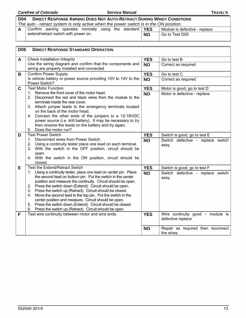
D04 DIRECT RESPONSE AWNING DOES NOT AUTO-RETRACT DURING WINDY CONDITIONS The auto - retract system is only active when the power switch is in the ON position. A Confirm awning operates normally using the standard
extend/retract switch with power on. YES Module is defective - replace NO Go to Test D05
D05 DIRECT RESPONSE STANDARD OPERATION
A Check Installation Integrity Use the wiring diagram and confirm that the components and wiring are properly installed and connected
YES Go to test B NO Correct as required
B Confirm Power Supply Is vehicle battery or power source providing 10V to 14V to the Power Switch?
YES Go to test C NO Correct as required
C Test Motor Function 1. Remove the front cover of the motor head. 2. Disconnect the red and black wires from the module to the
terminals inside the rear cover. 3. Attach jumper leads to the emergency terminals located
on the back of the motor head. 4. Connect the other ends of the jumpers to a 12-18VDC
power source (i.e. drill battery). It may be necessary to try then reverse the leads on the battery and try again.
5. Does the motor run?
YES Motor is good, go to test D
NO Motor is defective - replace
D Test Power Switch 1. Disconnect wires from Power Switch. 2. Using a continuity tester place one lead on each terminal. 3. With the switch in the OFF position, circuit should be
open. 4. With the switch in the ON position, circuit should be
closed.
YES Switch is good, go to test E
NO Switch defective - replace switch assy.
E Test the Extend/Retract Switch 1. Using a continuity tester, place one lead on center pin. Place
the second lead on bottom pin. Put the switch in the center position and measure the continuity. Circuit should be open.
2. Press the switch down (Extend). Circuit should be open. 3. Press the switch up (Retract). Circuit should be closed. 4. Move the second lead to the top pin. Put the switch in the
center position and measure. Circuit should be open. 5. Press the switch down (Extend). Circuit should be closed. 6. Press the switch up (Retract). Circuit should be open
YES Switch is good, go to test F
NO Switch defective - replace switch assy.
F Test wire continuity between motor and wire ends. YES Wire continuity good – module is defective replace
NO Repair as required then reconnect the wires.
TRAVEL'R Service Manual Carefree of Colorado
14 052540-301r5
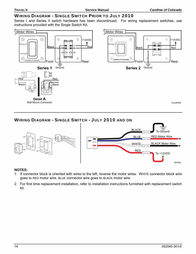
WIRING DIAGRAM - SINGLE SWITCH PRIOR TO JULY 2010 Series I and Series II switch hardware has been discontinued. For wiring replacement switches, use instructions provided with the Single Switch Kit.
TravelR008
Carefree of ColoradoFront Rear
Black Red
Ground
+12VDC
Motor Wires
L NL
NBlack Black
Red Red
Detail AWall Mount Connector
Front Rear
Black Red
Carefree of Colorado
65B
5A
32B
2A
Motor Wires
Series 1 Series 2
+12VDC
Ground
WIRING DIAGRAM - SINGLE SWITCH - JULY 2010 AND ON
SK005a
RETRACT
EXTEND
Carefree of Colorado
To Ground
To +12VDC
BLACK Motor Wire
RED Motor Wire
RED
BLACK
WHITE
BLUE
NOTES: 1. If connector block is oriented with wires to the left, reverse the motor wires. WHITE connector block wire
goes to RED motor wire, BLUE connector wire goes to BLACK motor wire.
2. For first time replacement installation, refer to installation instructions furnished with replacement switch kit.
Carefree of Colorado Service Manual TRAVEL'R
052540-301r5 15
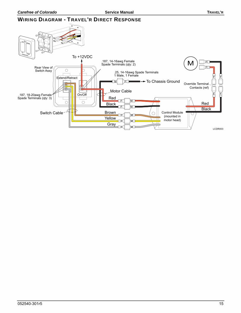
WIRING DIAGRAM - TRAVEL'R DIRECT RESPONSE
GrayYellowBrown
RedBlack
To +12VDC
To Chassis Ground
On/Off
Extend/Retract
RedBlack
Switch Cable
Motor Cable
Override TerminalContacts (ref)
Control Module(mounted inmotor head)
Rear View ofSwitch Assy
MF
MF
MF
MF
MF
FM
F F
F F
F
F
LCDR003
.25, 14-16awg Spade Terminals1 Male, 1 Female
.187, 14-16awg FemaleSpade Terminals (qty: 2)
.187, 18-20awg FemaleSpade Terminals (qty: 3)
RETRACT
ON
EXTENDAwning Control
OFF
TRAVEL'R Service Manual Carefree of Colorado
16 052540-301r5
STANDARD MAINTENANCE Maintaining the Carefree Manual Patio Awning is easy. Just follow these basic steps: Always operate the awning according to the instructions. Periodically check that the fasteners are tight. Tighten if necessary. Keep the awning fabric and arms clean.
FABRIC CARE CAUTION
DO NOT USE OIL BASED CLEANERS OR ANY CAUSTIC, GRANULATED, OR ABRASIVE TYPE CLEANERS ON YOUR
CAREFREE PRODUCT.
1. One of the best ways to keep the fabric looking good and to delay the need for deep or vigorous cleanings is to hose fabrics off on a monthly basis with clear water. This practice will help prevent dirt from becoming deeply imbedded in the fabric. In most environments, a thorough cleaning will be needed every two to three years.
2. When it’s time for a thorough cleaning, the fabric can be cleaned while still on an awning frame. For Vinyl Fabric – Use a soft brush and warm water with soap. For Acrylic Fabric – Use a stiff brush and warm water with soap.
3. When cleaning the fabric, it is important to observe the following: Always use a natural soap, never detergent. Water should be cold to lukewarm, never more than 100F. Air-dry only. Never apply heat to the fabric. Always allow the fabric to dry thoroughly before rolling up the awning.
Mildew Mildew is a fungus growth that looks like dirt. Vinyl coated polyester fabrics are mildew resistant because of a chemical biocide in the vinyl coating. Under ordinary conditions, mildew will not appear. However, in areas where high temperature and humidity are common, mildew can be a problem and required the material to be washed more frequently. Thoroughly rinse the fabric with clean water and allow to air dry completely before rolling up the awning.
Pooling When water collects on the top of the fabric, this is known as "pooling". This can occur during inclement weather or if a running air conditioner discharges over the awning. The water is dumped when the awning is retracted. It is recommended that if water accumulates on the top; retract the awning in steps (8"-12") to dump the water. This will help prevent the fabric from stretching or distorting.
The effects of wind and rain on an awning are unpredictable. Severe damage to the awning and the vehicle may result. IF WIND OR EXTENDED PERIODS OF RAIN ARE EXPECTED, ROLL UP THE AWNING AND
SECURE FOR TRAVEL.
ARM CARE The best method of keeping the arms and braces operating smoothly is to clean them. Dirt and debris can cause the channels not to slide easily.
NOTE: Avoid introducing water into the motorized housings.
Periodically wash out the channels with running water (i.e. a hose) to keep them clean. If the arms still do not move easily, lightly spray the contact and pivot points with a dry silicone lubricant after the arms have been cleaned and dried thoroughly.
Hardware Maintenance Replace any parts that become damaged. Periodically check all mounting hardware, screws, lags, etc., and re-tighten when necessary.
Carefree of Colorado Service Manual TRAVEL'R
052540-301r5 17
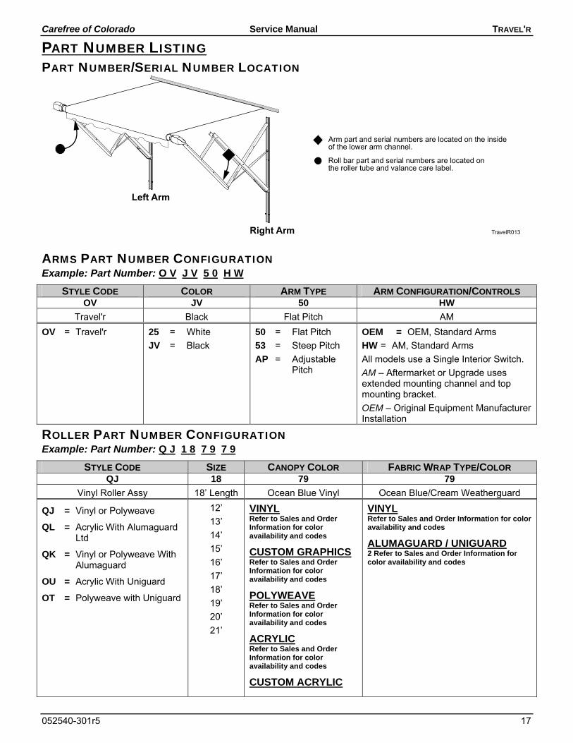
PART NUMBER LISTING PART NUMBER/SERIAL NUMBER LOCATION
TravelR013
Arm part and serial numbers are located on the insideof the lower arm channel.
Roll bar part and serial numbers are located onthe roller tube and valance care label.
Left Arm
Right Arm
ARMS PART NUMBER CONFIGURATION Example: Part Number: O V J V 5 0 H W
STYLE CODE COLOR ARM TYPE ARM CONFIGURATION/CONTROLS OV JV 50 HW
Travel'r Black Flat Pitch AM
OV = Travel'r 25 = White
JV = Black
50 = Flat Pitch
53 = Steep Pitch
AP = Adjustable Pitch
OEM = OEM, Standard Arms
HW = AM, Standard Arms
All models use a Single Interior Switch.
AM – Aftermarket or Upgrade uses extended mounting channel and top mounting bracket.
OEM – Original Equipment Manufacturer Installation
ROLLER PART NUMBER CONFIGURATION Example: Part Number: Q J 1 8 7 9 7 9
STYLE CODE SIZE CANOPY COLOR FABRIC WRAP TYPE/COLOR QJ 18 79 79
Vinyl Roller Assy 18’ Length Ocean Blue Vinyl Ocean Blue/Cream Weatherguard
QJ = Vinyl or Polyweave
QL = Acrylic With Alumaguard Ltd
QK = Vinyl or Polyweave With Alumaguard
OU = Acrylic With Uniguard
OT = Polyweave with Uniguard
12’
13’
14’
15’
16’
17’
18’
19’
20’
21’
VINYL Refer to Sales and Order Information for color availability and codes
CUSTOM GRAPHICS Refer to Sales and Order Information for color availability and codes
POLYWEAVE Refer to Sales and Order Information for color availability and codes
ACRYLIC Refer to Sales and Order Information for color availability and codes
CUSTOM ACRYLIC
VINYL Refer to Sales and Order Information for color availability and codes
ALUMAGUARD / UNIGUARD 2 Refer to Sales and Order Information for color availability and codes
TRAVEL'R Service Manual Carefree of Colorado
18 052540-301r5
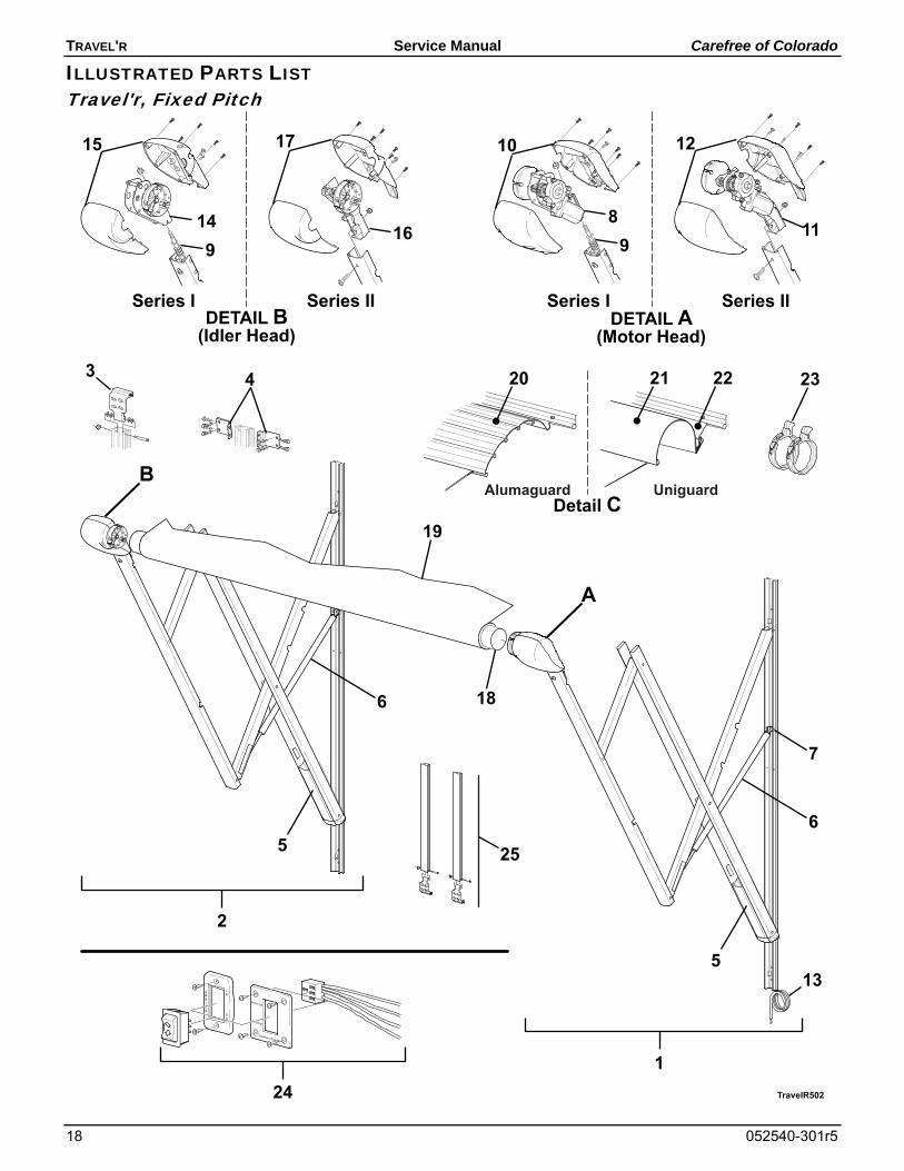
ILLUSTRATED PARTS LIST Travel'r, Fixed Pitch
TravelR502
6
5
1
2
DETAIL A(Motor Head)
Series I Series IIDETAIL B
(Idler Head)
Series I Series II
56
A
B
10
11
18
19
89
1215
149
17
16
24
13
25
Detail CAlumaguard
20 21 22
Uniguard
23
7
3 4
RETRACT
EXTEND
Carefree of Colorado
Carefree of Colorado Service Manual TRAVEL'R
052540-301r5 19
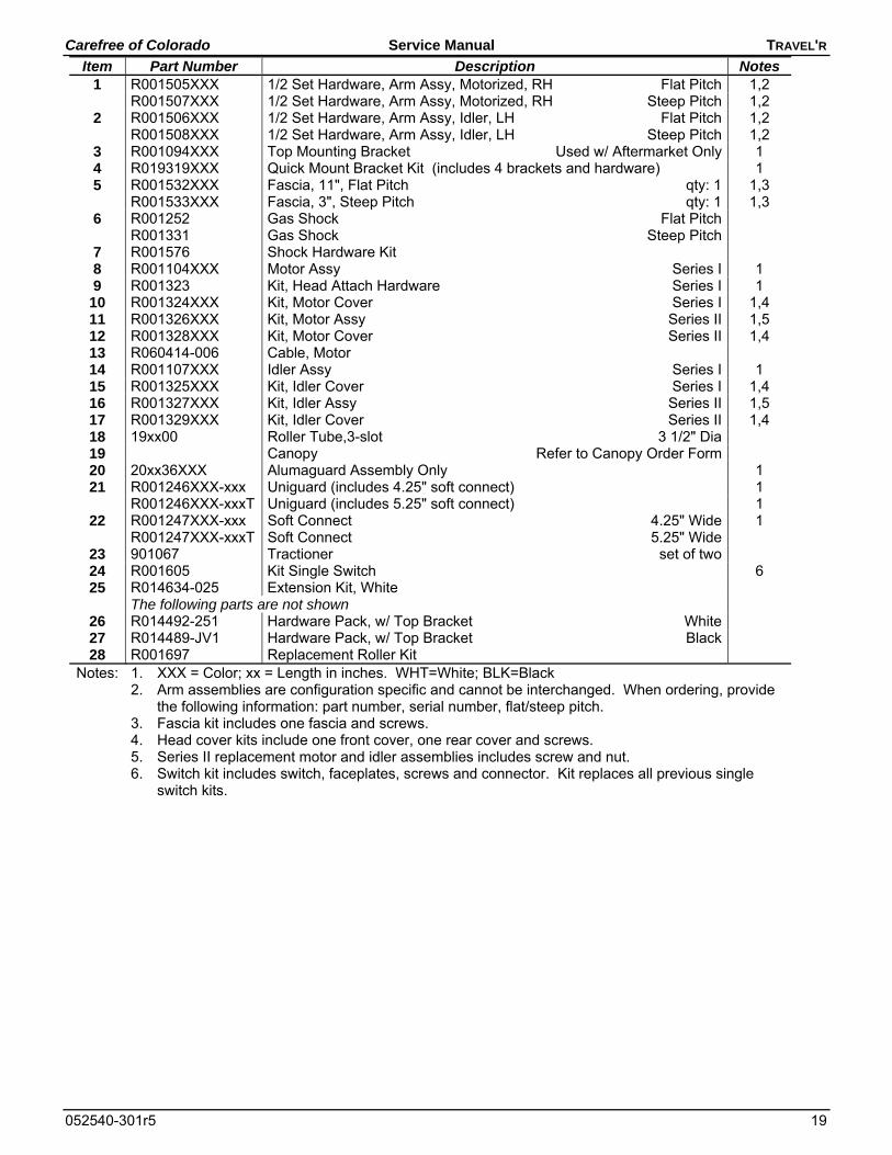
Item Part Number Description Notes 1 R001505XXX 1/2 Set Hardware, Arm Assy, Motorized, RH Flat Pitch 1,2 R001507XXX 1/2 Set Hardware, Arm Assy, Motorized, RH Steep Pitch 1,2
2 R001506XXX 1/2 Set Hardware, Arm Assy, Idler, LH Flat Pitch 1,2 R001508XXX 1/2 Set Hardware, Arm Assy, Idler, LH Steep Pitch 1,2
3 R001094XXX Top Mounting Bracket Used w/ Aftermarket Only 1 4 R019319XXX Quick Mount Bracket Kit (includes 4 brackets and hardware) 1 5 R001532XXX Fascia, 11", Flat Pitch qty: 1 1,3 R001533XXX Fascia, 3", Steep Pitch qty: 1 1,3
6 R001252 Gas Shock Flat Pitch R001331 Gas Shock Steep Pitch
7 R001576 Shock Hardware Kit 8 R001104XXX Motor Assy Series I 1 9 R001323 Kit, Head Attach Hardware Series I 1 10 R001324XXX Kit, Motor Cover Series I 1,4 11 R001326XXX Kit, Motor Assy Series II 1,5 12 R001328XXX Kit, Motor Cover Series II 1,4 13 R060414-006 Cable, Motor 14 R001107XXX Idler Assy Series I 1 15 R001325XXX Kit, Idler Cover Series I 1,4 16 R001327XXX Kit, Idler Assy Series II 1,5 17 R001329XXX Kit, Idler Cover Series II 1,4 18 19xx00 Roller Tube,3-slot 3 1/2" Dia 19 Canopy Refer to Canopy Order Form 20 20xx36XXX Alumaguard Assembly Only 1 21 R001246XXX-xxx Uniguard (includes 4.25" soft connect) 1
R001246XXX-xxxT Uniguard (includes 5.25" soft connect) 1 22 R001247XXX-xxx Soft Connect 4.25" Wide 1
R001247XXX-xxxT Soft Connect 5.25" Wide 23 901067 Tractioner set of two 24 R001605 Kit Single Switch 6 25 R014634-025 Extension Kit, White
The following parts are not shown 26 R014492-251 Hardware Pack, w/ Top Bracket White 27 R014489-JV1 Hardware Pack, w/ Top Bracket Black 28 R001697 Replacement Roller Kit
Notes: 1. XXX = Color; xx = Length in inches. WHT=White; BLK=Black 2. Arm assemblies are configuration specific and cannot be interchanged. When ordering, provide
the following information: part number, serial number, flat/steep pitch. 3. Fascia kit includes one fascia and screws. 4. Head cover kits include one front cover, one rear cover and screws. 5. Series II replacement motor and idler assemblies includes screw and nut. 6. Switch kit includes switch, faceplates, screws and connector. Kit replaces all previous single
switch kits.
TRAVEL'R Service Manual Carefree of Colorado
20 052540-301r5
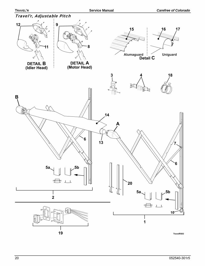
Travel'r, Adjustable Pitch
TravelR503
6
1
DETAIL A(Motor Head)
DETAIL B(Idler Head)
A
B
13
912
11
14
2
8
6
3
10
Detail CAlumaguard
15 16 17
Uniguard
18
20
7
19
4
5a 5b
5a 5b
RETRACT
EXTEND
Carefree of Colorado
Carefree of Colorado Service Manual TRAVEL'R
052540-301r5 21
Item Part Number Description Notes 1 R001642XXX 1/2 Set Hardware, Arm Assy, Motorized, RH 1 2 R001643XXX 1/2 Set Hardware, Arm Assy, Idler, LH 1 3 R001094XXX Top Mounting Bracket Used w/ Aftermarket Only 1 4 R019319XXX Quick Mount Bracket Kit (includes 4 brackets and hardware) 1 5a R019284-005 Fascia w/ external stop pin, White qty 2 4 R019284-006 Fascia w/ external stop pin, Black qty 2 4
5b R019678-005 Fascia w/o stop, White qty 2 4 R019678-006 Fascia w/o stop, Black qty 2 4 6 R001252 Gas Shock 7 R001576 Shock Hardware Kit 8 R001326XXX Kit, Motor Assy 1 9 R001328XXX Kit, Motor Cover 1 10 R060414-006 Cable, Motor 11 R001327XXX Kit, Idler Assy 1,2 12 R001329XXX Kit, Idler Cover 1,2 13 19xx00 Roller Tube, 3-slot 3 1/2" Dia 14 Canopy Refer to Canopy Order Form 15 20xx36XXX Alumaguard Assembly Only 1 16 R001246XXX-xxx Uniguard (includes 4.25" soft connect) 1 R001246XXX-xxxT Uniguard (includes 5.25" soft connect) 1
17 R001247XXX-xxx Soft Connect 4.25" Wide 1 R001247XXX-xxxT Soft Connect 5.25" Wide 1
18 901067 Tractioner set of two 19 R001605 Switch Kit 3 20 R014634-025 Extension Kit White The following parts are not shown
21 R014492-251 Hardware Pack, w/Top Bracket White 22 R014492-JV1 Hardware Pack, w/Top Bracket Black 23 R001167 Replacement Roller Kit
Notes: 1. XXX = Color; xxx= Length in inches. 2. Head cover kits include one front cover, one rear cover and screws. 3. Switch kit includes switch, faceplates, screws and connector. Kit replaces all previous single switch
kits. 4. Fascia kits include two fascia plates and screws.
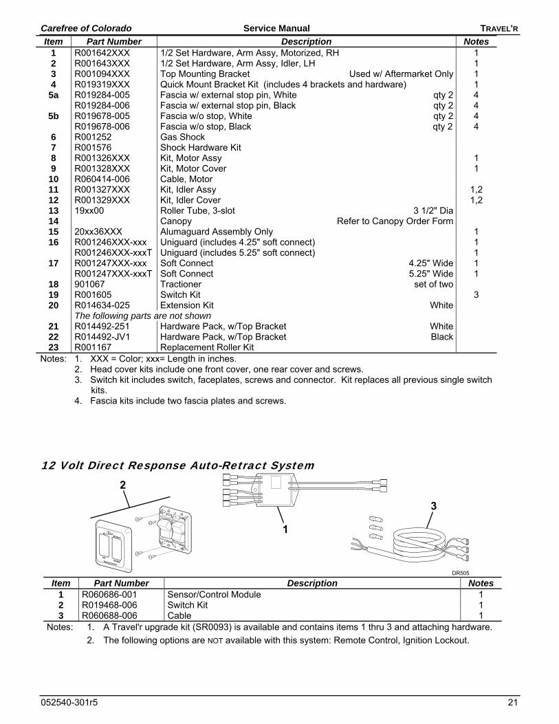
12 Volt Direct Response Auto-Retract System
RETRACT
ON
EXTENDAwning Control
OFF
DR505
2
1
3
Item Part Number Description Notes
1 R060686-001 Sensor/Control Module 1 2 R019468-006 Switch Kit 1 3 R060688-006 Cable 1
Notes: 1. A Travel'r upgrade kit (SR0093) is available and contains items 1 thru 3 and attaching hardware.
2. The following options are NOT available with this system: Remote Control, Ignition Lockout.

TRAVEL'R Service Manual Carefree of Colorado
22 052540-301r5
NOTES: