Embed Size (px)
Citation preview
Service manual
Torktumlare T4130, T4130C
Quickdry, Quickdry CTyp N1130
487 03 30 71/EN 2011.07.21
Service manual in original language

2
3
Servicemanual
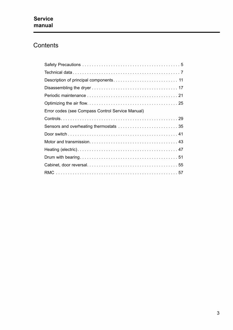
Contents
Safety Precautions . . . . . . . . . . . . . . . . . . . . . . . . . . . . . . . . . . . . . . . . . 5
Technical data . . . . . . . . . . . . . . . . . . . . . . . . . . . . . . . . . . . . . . . . . . . . . 7
Description of principal components . . . . . . . . . . . . . . . . . . . . . . . . . . . 11
Disassembling the dryer . . . . . . . . . . . . . . . . . . . . . . . . . . . . . . . . . . . . 17
Periodic maintenance . . . . . . . . . . . . . . . . . . . . . . . . . . . . . . . . . . . . . . 21
Optimizing the air flow . . . . . . . . . . . . . . . . . . . . . . . . . . . . . . . . . . . . . . 25
Error codes (see Compass Control Service Manual)
Controls . . . . . . . . . . . . . . . . . . . . . . . . . . . . . . . . . . . . . . . . . . . . . . . . . 29
Sensors and overheating thermostats . . . . . . . . . . . . . . . . . . . . . . . . . 35
Door switch . . . . . . . . . . . . . . . . . . . . . . . . . . . . . . . . . . . . . . . . . . . . . . 41
Motor and transmission . . . . . . . . . . . . . . . . . . . . . . . . . . . . . . . . . . . . . 43
Heating (electric) . . . . . . . . . . . . . . . . . . . . . . . . . . . . . . . . . . . . . . . . . . 47
Drum with bearing . . . . . . . . . . . . . . . . . . . . . . . . . . . . . . . . . . . . . . . . . 51
Cabinet, door reversal . . . . . . . . . . . . . . . . . . . . . . . . . . . . . . . . . . . . . . 55
RMC . . . . . . . . . . . . . . . . . . . . . . . . . . . . . . . . . . . . . . . . . . . . . . . . . . . 57
Safety PrecautionsServicemanual
44
5
Safety PrecautionsServicemanual
5
ServicemanualServicemanual
Safety PrecautionsDo not dry unwashed items in the machineThe machine is not to be used if industrial chemicals have been used for cleaning.Do not allow minors to use the machine.Do not hose down the machine with water.The machine's door lock must under no circumstances be bypassed.Items that have been soiled with substances such as cooking oil, acetone, alcohol, petrol, kerosene, spot removers, turpentine, waxes and wax removers should be washed in hot water with an extra amount of detergent before being dried in the machine.Items such as foam rubber (latex foam), shower caps, waterproof textiles, rubber backed articles and clothes or pillows fitted with foam rubber pads should not be dried in the machine.Fabric softeners or similar products should be used as specified by the fabric softener instructions.The machine may not be used to dry floor mops that contain polypropylene.The final part of a drying cycle occurs without heat (cool down cycle) to ensure that the items are left at a temperature that ensures that the items will not be damaged.WARNING. Never stop the machine before the end of the drying cycle unless all items are quickly removed and spread out so that the heat is dissipiated.Remove garments from the machine as soon as they are dried. This prevents them from becoming creased and reduces the risk of spontaneous ignition.If the machine develops a fault, this must be reported to the person in charge as soon as possible. This is important both for your safety and that of others.The machine must not be located where a door, sliding door, etc., can block the machine's doorThe machine is not intended to be used by people (including minors) with reduced physical or mental capacity or lack of experience and knowledge. Such people must be instructed in the use of the machine by a person who has responsibility for their safety. Minors must be supervised to ensure that they do not play with the machine.Adequate ventilation has to be provided to avoid the back flow of gases into the room for appliances burning other fuels, including open fires.Gas heated tumble dryer:The machine is not to be installed in rooms containing cleaning machines with perchloroethylene, TRICHLOROETHYLENE or CHLOROFLUOROCONTAINING HYDROCARBONS as cleaning agents.If you can smell gas,• Do not switch on any equipment• Do not use electrical switches• Do not use telephones in the building• Evacuate the room, building or area• Contact the person responsible for the machine
In order to prevent damage to the electronics (and other parts) that may occur as the result of condensation, the machine should be placed in room temperature for 24 hours before being used for the first time.

6
7
2. Technical dataServicemanual
Contents
Technical data, type T4130 . . . . . . . . . . . . . . . . . . . . . . . . . . . . . . . . . . . 8
Technical data, motor specifications . . . . . . . . . . . . . . . . . . . . . . . . . . . . 9
Technical dataServicemanual
Technical dataServicemanual
8
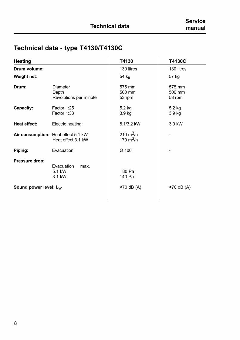
Technical data - type T4130/T4130C
Heating T4130 T4130CDrum volume: 130 litres 130 litres
Weight net: 54 kg 57 kg
Drum: Diameter 575 mm 575 mm Depth 500 mm 500 mm Revolutions per minute 53 rpm 53 rpm
Capacity: Factor 1:25 5 .2 kg 5 .2 kg Factor 1:33 3 .9 kg 3 .9 kg
Heat effect: Electric heating: 5 .1/3 .2 kW 3 .0 kW Air consumption: Heat effect 5 .1 kW 210 m3/h - Heat effect 3 .1 kW 170 m3/h
Piping: Evacuation Ø 100 -
Pressure drop: Evacuation max . 5 .1 kW 80 Pa 3 .1 kW 140 Pa
Sound power level: Lw <70 dB (A) <70 dB (A)

9
Technical dataServicemanual
Technical data - motor specifications
T4130 T4130C
Dryer with reversal:
Motor 3-phase: Effect 130 W 130 W Revolutions per minute: 50 Hz 2730 rpm 2730 rpm 60 Hz 3330 rpm 3330 rpm Motor 1-phase: Effect 130 W 130 W Revolutions per minute: 50 Hz 2730 rpm 2730 rpm 60 Hz 3330 rpm 3330 rpm

10

11
3. Description of principal componentsServicemanual
Contents
Description . . . . . . . . . . . . . . . . . . . . . . . . . . . . . . . . . . . . . . . . . . . . . . 12
Position of components . . . . . . . . . . . . . . . . . . . . . . . . . . . . . . . . . . . . . 14
11
Description of principal componentsServicemanual

Description of principal componentsServicemanual
12
DescriptionDryer type T4130/T4130C are available as electric heated .
Programs - Compass Control The dryer has a microprocessor . The microprocessor control has different functions including:
• Drum reversing for less tangling of large items.
• Serviceprogram for adjustment parameters eg. temperature, cool-down time.
• Dryer functions monitoring - errors occurred during the program sequence are registered in the log . Some of the error codes are shown on the display at the same time .
• RMC (Residual Moisture Control), the dryer stops automatically when the clothes have reached the required residual moisture level.
Knob operation for Program selection
Door
Display

13
Description of principal componentsServicemanual
Loading doorNormally the dryer has a right-hinged door .
The door is, however, reversible (see section "Cabinet, door reversal") .
A door switch ensures that the dryer stops automatically if the dryer is opened during the program sequence, see section "Door switch" .
Knob operation Turn and select with the knob operation and following appears:
• Program selection.
• Start button.
• Language selection.
Coin drop / card readerThe dryer can be mounted with a coin drop, a card-start system, or it can be prepared for field installation of a card start system .
MotorThe dryer has one motor . The motor operates the blower and the drum .
8 2
3
1
5
5
5
6
2
Description of principal componentsServicemanual
14
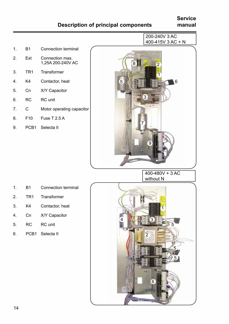
1 . B1 Connection terminal
2 . Ext Connection max . 1,25A 200-240V AC
3 . TR1 Transformer
4 . K4 Contactor, heat
5 . Cn X/Y Capacitor
6 . RC RC unit
7 . C Motor operating capacitor
8 . F10 Fuse T 2 .5 A
9 . PCB1 Selecta II
1 . B1 Connection terminal
2 . TR1 Transformer
3 . K4 Contactor, heat
4 . Cn X/Y Capacitor
5 . RC RC unit
6 . PCB1 Selecta II
200-240V 3 AC400-415V 3 AC + N
400-480V + 3 ACwithout N
15 6
7
9
4 3

10 2
61
4
3
7
9
8
5
10
2
3
4
5
6
77
7
9
8
15
Description of principal componentsServicemanual
1 . B1 Connection terminal
2 . TR1 Transformer
3 . K4 Contactor, heat
4 . K1 Contactor (drum right)
5 . K2 Contactor (drum left)
6 . Cn X/Y capacitor
7 . RC RC unit
8 . PCB1 Selecta II
9 . PCB5 Relay for M3
10 . F10 Fuse T0 .5 A
200-240V 3 AC, 230-240V 1 AC400-415V 3 AC+N
1 . B1 Connection terminal
2 . Ext Connection max 1,25A 230V AC
3 . TR1 Transformer
4 . K4 Contactor, heat
5 . Cn X/Y Capacitor
6 . RC RC unit
7 . C Motor operating c apacitor
8 . PCB1 Selecta II
9 . PCB5 Relay for M3
10 . F10 Fuse T2 .5 A
400-440V + 3 ACwithout N
1

Description of principal componentsServicemanual
16
T4130C:
Condensator C2 for fan motor, fig . 1 .
2
1
T4130C:Only 400-440V 3 AC without N
Autotransformer TR2 for condensate pump and fan motor, fig . 2 .

Disassembling the dryerServicemanual
17
Content
Disassembling the tumble dryer . . . . . . . . . . . . . . . . . . . . . . . . . . . . . . . 18

Disassembling the dryerServicemanual
18
Recommended sequence1 . Disconnect the power supply .
2 . Dismount the top plate and the heat shield, fig . 2 .
Warning! After disconnecting the power, there might still be power on the suppression capacitor . It can be discharged by pushing down the heating contactor with a screwdriver, fig . 1 .
3 . Dismount the protective screen at the air vent (Standard tumble dryer) . Dismount the plastic cover (Condensate tumble dryer), fig . 3 .
4 . Loosen the drive belt on the drum from the motor and pull out the hose to the drain, fig . 4 .
1
2
33 4
Suppression capacitor
Heatingcontactor

Disassembling the dryerServicemanual
19
5
6
Recommended sequence
5 . Release the bearing rollers: Loosen the screws and turn the hexagon key 1/2 turn clockwise, fig . 5 .
6 . Dismount the discharge branch and the multi-plug for the fan (Condensate tumble dryer), fig . 6 .
7 . Dismount the heat cover and disengaged the heat element cables .
8 . Cut the cable ties . Carefully pull the cables in through the hole and keep the platic ring around the cables, fig . 7 + 8 .
8
7

Disassembling the dryerServicemanual
20
Recommended sequence
9 . Remove the spade-shaped connector for the earthing conductor (A) and the sliding contact (B) . Remove the cable from the terminal strip (C), fig . 9 .
Note! The earth conductor must be connected again for safety .
10 . Remove the four screws at the heating element .Remove the back plate, fig . 10 .
11. Lift the drum and the back plate jointly out of the cabinet, fig . 11 .
9
A
C
11
B
10

21
Periodic maintenanceServicemanual
Content
Periodic maintenance . . . . . . . . . . . . . . . . . . . . . . . . . . . 22

Periodic maintenanceServicemanual
22
Functional inspection
Functional inspection comprises:1 . Checking the door switch.2 . Test run.
1. Check the door switchCheck whether the safety lock works . The drum must stop when the door is opened . When the door is closed again, the tumbler must not start until the start button is pressed, fig . 1 .
2. Test runLet the tumble dryer work on a program with heat for 5 minutes; then check by opening the door and feeling with your hand whether the heating works .
MaintenanceThe following should be carried out at regular intervals, depending on the frequency of use.
Daily• Check that the drum stops when the door is
opened .
• Check that the lint screen in the door has been cleaned . The lint screen must be removed for cleaning . Use a soft brush or your hand . Remember to put the lint screen back in, fig . 2 .
• Check that the gaskets around the coarse filter/air condenser and the door gasket have been cleaned . Clean with a moist cloth .
• Check that the lint screen is not damaged.
• Check that the tumble dryer will not start until the start/stop button has been activated .
• On condensate tumble dryers, the air condenser must also be checked for lint and dust . Remove for cleaning .
1
2

23
Periodic maintenanceServicemanual
Monthly (On condensate tumble dryers)• At least once a month the condenser must be
cleaned of lint by rinsing it with water until the lamellae are clean. Soak in hot water if required, fig . 1 .
Quarterly/Semi-annually• Check that the fresh-air intake at the rear of the
dryer is not clogged by lint or blocked in any other way .
• Check that the drain system is tight and not clogged by lint/dust or blocked in any other way . Use a cable tie, fig . 2 .
• Clean drum and lifters with a mild detergent (using a sponge) at least once every quarter.
• Remove the coarse filter for lint removal.
• On condensate tumble dryers carry out the monthly cleaning described above .
• At least once a year a skilled expert should check the inside wearing parts of the tumble dryer and clean them of lint .
1
2
MaintenanceThe area surrounding the dryerFresh-air intake to the room
Check that the fresh-air intake to the room and the exhaust ducts/pipes from the room are not clogged by lint/dust or blocked in any other way .
Dryer areaCheck that the dryer area is clear and free from combustible materials, gasoline and other flammable vapours and liquids.
Cable tie

1
2
5
4
3
STATISTICS
RUN HOUR00000BACK=PRESS KNOB
STATISTICS
TRIP RUN HOURS00000BACK=PRESS KNOB
SERVICE HOURS COUNT
0BACK=PRESS KNOB
STATISTICSMENU 3-1
RUN HOURSPAYMENT SETTINGERROR LOGEXIT
MAIN MENUMENU 3
STATISTICSCONFIG 1CONFIG 2COIN VALUEADJUST DISPLAY
Periodic maintenanceServicemanual
24
STATISTICSThis menu contains information on running time, payment, settings and error codes, fig. 1.
Select the STATISTICS row and press the knob .
The display will now show a number of sub- menus containing the available statistics . Select the desired menu and press the knob, fig. 2.
• RUN HOURS • TRIP RUN HOURS • SERVICE HOURS COUNT • COIN COUNT 1 • COIN COUNT 2 • ERROR LOG
RUN HOURSSpecifies the total running hours, in hours, since the machine was installed and used for the first time, fig. 3.
TRIP RUN HOURSSpecifies the total running hours , in hours, since the running hours were last reset, fig. 4.
SERVICE HOURS COUNTCan be set for a number of hours to the next service interval. Confirm by pressing the knob, fig. 5.

25
Optimizing the air flowServicemanual Optimizing the air flowServicemanual
Contents
Outlet dimensioning . . . . . . . . . . . . . . . . . . . . . . . . . . . . . . . . . . . . . . . 26
Blower characteristic . . . . . . . . . . . . . . . . . . . . . . . . . . . . . . . . . . . . . . . 27
Drying time T4130C . . . . . . . . . . . . . . . . . . . . . . . . . . . . . . . . . . . . . . . 28

Optimizing the air flowServicemanual
26
Type Effect
kW
Optimumair volume
m3/h
Correspondingback pressure
Pa
Air volumeThe curves on the next page shows the characteristics of the dryer . By measuring or calculating the back pressure of the outlet pipe it is hereby possible to find the corresonding air flow into the room and through the dryer and exhaust .
It is important that the dryer has the correct air volume compared to each dryer’s effect . If the air flow is below the minimum, the dryer will be forced to switch the heating off thus prolonging the time it will take to dry the load .An air flow above the needed is unnecessary and can result in a cold laundry room and noise from the piping and outlet and in extreme cases prolonged drying time .
The condensate dryer does not have ventilation (evacuation) into the open .The air is circulated in a closed system between the dryer and condensing unit .
Table with air volume and dryer effectOptimum volume
T4130 5 .1 210 80
3 .2 170 140
Air flow

x = m3/h
Y = Pa
100 20000
50
100
150
200
250
300
x = m3/h
Y = Pa
100 20000
50
100
150
200
250
300
27
Optimizing the air flowServicemanual
X = Air consumptionY = Back pressure
The grey area marks the recommended working area .
Diagram with pressure drop curve type T4130.
T4130: 3 .2 kW
T4130: 5 .1 kW
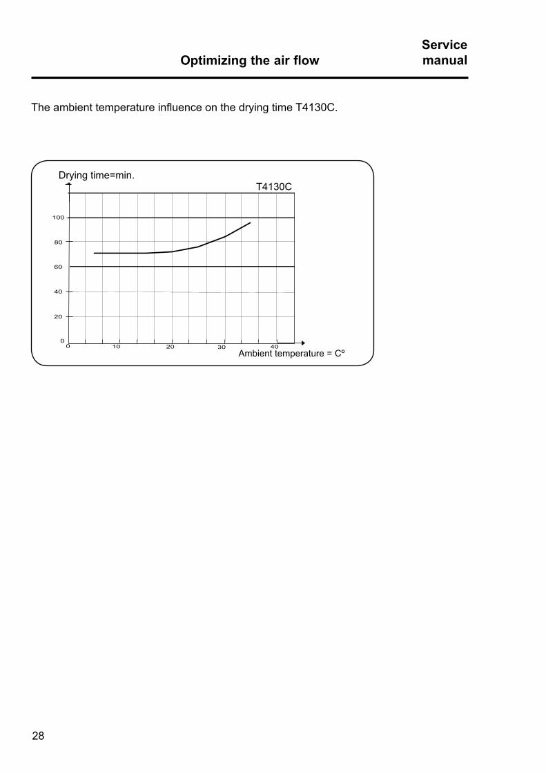
x = °C
Y = Min.
10 20 30 4000
20
40
60
80
100
Drying time=min .
Ambient temperature = Cº
Optimizing the air flowServicemanual
28
The ambient temperature influence on the drying time T4130C .
T4130C

Contents
Printed circuit board . . . . . . . . . . . . . . . . . . . . . . . . . . . . . . . . . . . . . . . 32
Connecting accessory systems . . . . . . . . . . . . . . . . . . . . . . . . . . . . . . 32
Connection to network/Central Panel . . . . . . . . . . . . . . . . . . . . . . . . . . 33
Programming . . . . . . . . . . . . . . . . . . . . . . . . . . . . . . . . . . . . . . . . . . . . . 34
Replacement of PCB . . . . . . . . . . . . . . . . . . . . . . . . . . . . . . . . . . . . . . 35
Circuit boards MUST be protected from static electricity!
Remember!
• Always use an earthed wrist strap.
• Without the antistatic wrapping, the board is unprotected.
• Keep all items that can cause static discharge (such as plastic bags, fabric, and the like) away from the circuit board .
• Items like plastic, foam plastic, nylon, or cellophane wrapping are all big generators of static electricity .
• Static electricity can not be felt, heard or seen till the voltage reaches 2500V .
• Board components can be damaged by static electricity under 100V.
29
ControlsServicemanual

ControlsServicemanual
30
Control PCB
Printed circuit boardThe PCB is placed behind the operating panels, fig . 1 .
The PCB contains a board with display, indicator lamps .
The PCB contains a button A for Switching to Programming mode,See description in Service Manual for Compass Control .
Connecting accessory systemsDifferent payment systems can be connected to the PCB .
1
31
ControlsServicemanual
1
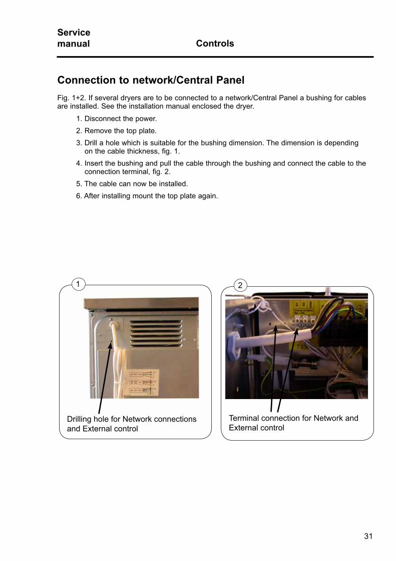
Connection to network/Central PanelFig . 1+2 . If several dryers are to be connected to a network/Central Panel a bushing for cables are installed . See the installation manual enclosed the dryer .
1 . Disconnect the power .2 . Remove the top plate .3 . Drill a hole which is suitable for the bushing dimension . The dimension is depending on the cable thickness, fig . 1 .4 . Insert the bushing and pull the cable through the bushing and connect the cable to the connection terminal, fig . 2 .5 . The cable can now be installed .6 . After installing mount the top plate again .
Drilling hole for Network connections and External control
2
Terminal connection for Network and External control

ControlsServicemanual
32
A
ProgrammingTo enter the programming mode press service button A .After pressing the service button A the display shows: 0 -- = Group 0.Program the dryer, see Service Manual for Compass Control for programming details .
High voltage on the printed circuit boardDo not touch the printed circuit board .The shaded areas indicate high voltage .
B

33
ControlsServicemanual
Replacement of PCBThe PCB is not serviceable . It must be replaced if it fails, see Compass Control Service Manual .
The PCB can be ordered as a spare part .
The spare part consists of: Printed circuit board with fuses in anti-static packing and instructions .
The PCB Selecta Control software is pre-programmed with specific features and may need to be “post-programmed” after installation .
Installation 1 . Disconnect the power supply to the dryer .
2 . Remove the top plate to access the defected print board . (See earlier in this section) .
3 . Remove the defective print board, but keep the 5 nuts for later use, fig . 1 .
4 . Mount the new print board from the kit .
5 . Mount the nuts where shown and tighten .
Follow the instructions from the kit when programming .
Following settings have to be programmed: (see Compass Control Service Manual)• Reversing (on or off). (Parameter 5-1-1).
• Heating type. (Parameter 5-1-2).
• Payment settings. (Time per coin, standby display value, display flashing). (Parameter 5-1-3).
• Panel type. (Parameter 5-1-4).
• Program type. (Parameter 5-1-5).
1
34
Service Manual for Compass ControlCertain parameters need to be set after installation, according to the characteristics of the dryer and the preferences of the owner .
See Service Manual for Compass Control for further details .
ControlsServicemanual

Contents
Overview, inlet air: . . . . . . . . . . . . . . . . . . . . . . . . . . . . . . . . . . . . 38 Overheating thermostat . . . . . . . . . . . . . . . . . . . . . . . . . . . . . . . . 39
Overview, outlet air: . . . . . . . . . . . . . . . . . . . . . . . . . . . . . . . . . . . 40 Overheating thermostat . . . . . . . . . . . . . . . . . . . . . . . . . . . . . . . . 41
Thermistor element (NTC sensor) . . . . . . . . . . . . . . . . . . . . . . . . 42
Sensors and overheating thermostatsServicemanual
35
Sensors and overheating thermostatsServicemanual
36
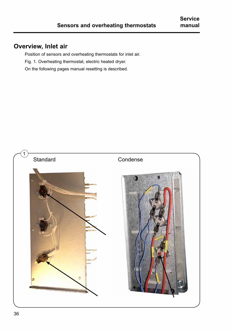
Overview, Inlet airPosition of sensors and overheating thermostats for inlet air .
Fig . 1 . Overheating thermostat, electric heated dryer .
On the following pages manual resetting is described .
1Standard Condense

37
Sensors and overheating thermostatsServicemanual
1
Inlet air - Overheating thermostatFunction
The inlet overheating thermostat opens in the event of overheating, and shuts off the dryer .
The thermostat has to be reset manually .
ResettingElectric heated dryer, fig . 1 and fig . 2 .
The overheating thermostat on the standard is located in the bottom on the dryer (A), fig . 1 . On the condense it is located on the rear side of the back plate (B), fig . 2 .
In order to reset the thermostat, shut off power and remove the back plate, see the section "Disassembling the dryer" and press the reset button A on the thermostat, or just press the button B on the back plate .
It is not necessary to disassemble the tumbler .
Error codeThe following error code is related to this section .
E08See Service Manual for Compass Control for more information .
A B
2
Standard Condense

Sensors and overheating thermostatsServicemanual
38
Overview, Outlet airPositioning sensors and overheating thermostats for outlet air .
Fig . 1 . Overheating thermostat and thermistor element for electric heated dryers .
On the following pages replacement and manual resetting are described .
1Standard Condense

39
Sensors and overheating thermostatsServicemanual
1
Outlet air - Overheating thermostatFunction
The outlet air overheating thermostat is located in the outlet air flow .
The overheating thermostat opens in event of overheating .
The thermostat opens automatically and has to be reset manually .
ResettingElectric heated dryer, fig . 1 .
The overheating thermostat on the standard dryer is located behind the back plate of the dryer at the bottom and on the right side of the dryer (A) . On the condense dryer it is located on the flange at the rear side of the door opening (B) .
In order to reset the thermostat, shut of power and remove the back plate, see the section "Disassembling the dryer" and press the reset button A or unscrew the two screws on the flange and press the reset buttom B.It is not necessary to disassemble the tumbler .
Error codeThe following error code is related to this section .
E08See Service Manual for Compass Control for more information .
Standard Condense
A
B

Sensors and overheating thermostatsServicemanual
40
Outlet air - Thermistor element (NTC sensor)Function
The sensor measures the temperature in the outlet air and the signal is returned to the main circuit board . The main circuit board turns the heating unit off when the outlet air thermistor indicates that the required temperature has been reached.
The resistance of this device is normally 4 to 6 kOhms at 20°C (68F) and it drops as its temperature increases .
The sensor A (standard) is mounted on the same housing as the outlet air overheating thermostat . The sensor B (condense) is mounted on the the same flange, but to the left as the outlet overheating thermostat .
Error codesThe following error codes are related to this section .
E04, E18 See Service Manual for Compass Control for more information .
1Standard Condense
A
B

41
Door switch and lint filter switchServicemanual Door switch
Contents
Door switch, description and replacement . . . . . . . . . . . . . . . . . . . . . . 44

Door switch and lint filter switchServicemanual
42
1
2
Door switch
Door switchDescription
The door switch A engages the network voltage directly onto the control unit . If the door is opened while the program is running, all power-consuming units are disengaged, fig . 1 .
The door switch is located inside the drum, at the rear of the front cabinet .
ReplacementAccess to repairing/replacing the door switch can be gained most easily through the tumbler aperture, fig . 2 . It is not necessary to disassemble the tumbler .
Tip! During installation of the door switch care should be taken not to wind any wires around the switch .
Check of functions can be done at service mode .
A

Motor and transmissionServicemanual
43
Content
Motor . . . . . . . . . . . . . . . . . . . . . . . . . . . . . . . . . . . . 46
Condensate tumble dryer motors . . . . . . . . . . . . . . . . . . . . . 48
Motor and transmissionServicemanual
44
1
2
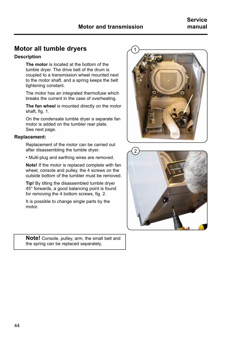
Note! Console, pulley, arm, the small belt and the spring can be replaced separately .
Motor all tumble dryersDescription
The motor is located at the bottom of the tumble dryer . The drive belt of the drum is coupled to a transmission wheel mounted next to the motor shaft, and a spring keeps the belt tightening constant .
The motor has an integrated thermofuse which breaks the current in the case of overheating .
The fan wheel is mounted directly on the motor shaft, fig . 1 .
On the condensate tumble dryer a separate fan motor is added on the tumbler rear plate . See next page .
Replacement:Replacement of the motor can be carried out after disassembling the tumble dryer .
• Multi-plug and earthing wires are removed.
Note! If the motor is replaced complete with fan wheel, console and pulley, the 4 screws on the outside bottom of the tumbler must be removed .
Tip! By tilting the disassembled tumble dryer 45° forwards, a good balancing point is found for removing the 4 bottom screws, fig . 2 .
It is possible to change single parts by the motor .

45
Motor and transmissionServicemanual
Replacing parts on transmission
1 . Disconnect the power supply to the dryer .
2 . Dismount drum belt and motor .
3 . Fig . 1 . Dismount spring B .
4 . Fig . 1 . Dismount transmission belt C .
5 . Fig . 1 . Dismount snap ring D, washer and arm with idler .
6 . Mount new arm with idler by turning it back and forth, lubricate the shaft end with copper grease .
Do not hit or use excessive force on the arm!
7 . Mount snap ring D .
8 . Mount transmission belt C .
9 . Fig . 3 . Mount new spring . It is important that the spring is mounted on the outer hoop at the bottom .
10 . Mount the complete motor .
11 . Mount drum belt .
12 . Assemble the dryer and test it .
13 . Check that the belts go correctly around the wheel .
1
B
C
D
2
3
Motor and transmissionServicemanual
46
1
2
3
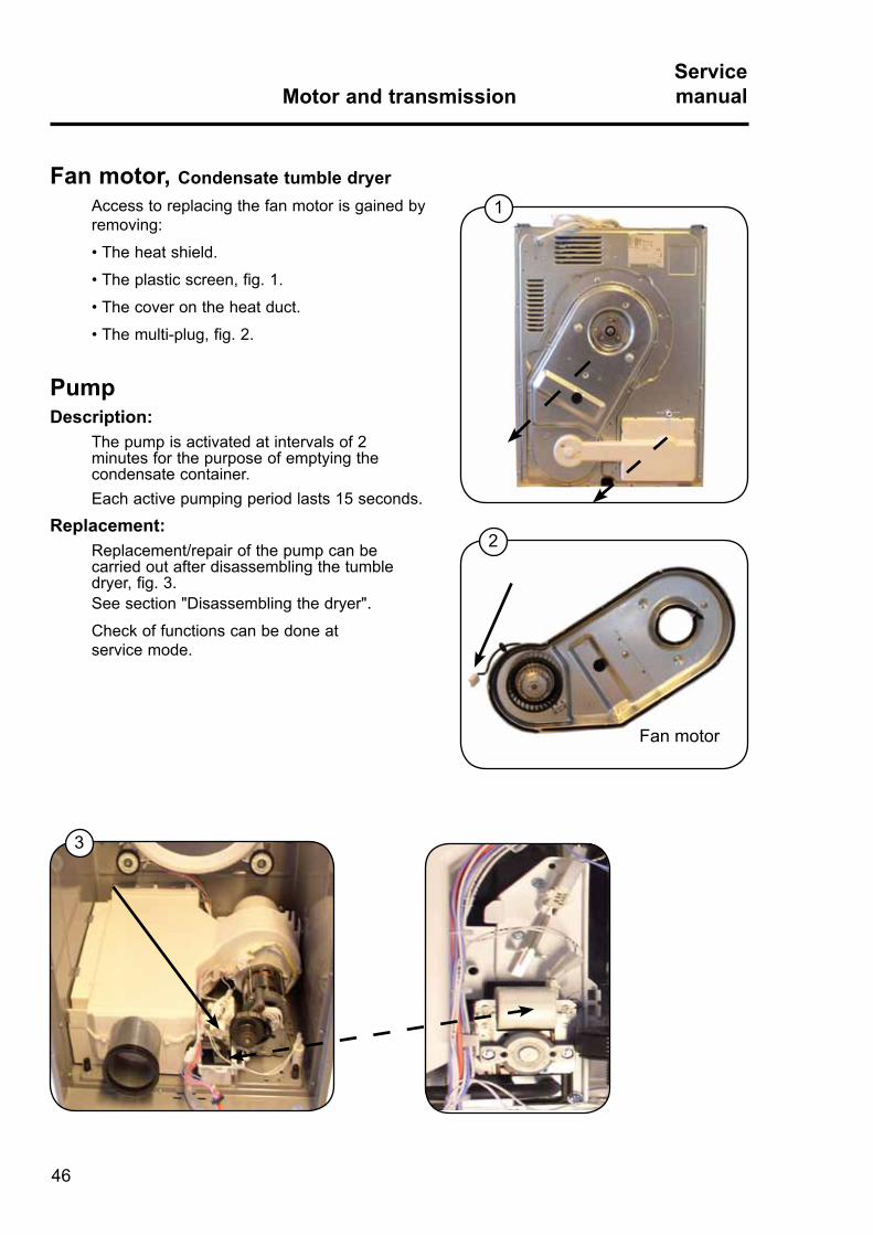
Fan motor, Condensate tumble dryerAccess to replacing the fan motor is gained by removing:
• The heat shield.
• The plastic screen, fig. 1.
• The cover on the heat duct.
• The multi-plug, fig. 2.
PumpDescription:
The pump is activated at intervals of 2 minutes for the purpose of emptying the condensate container .Each active pumping period lasts 15 seconds .
Replacement:Replacement/repair of the pump can be carried out after disassembling the tumble dryer, fig . 3 . See section "Disassembling the dryer" .Check of functions can be done at service mode .
Fan motor
47
HeatingServicemanual
Content
Heating system Standard dryer . . . . . . . . . . . . . . . . . . . . . . . . . . . . . . . . 50
Heating system Condensate dryer . . . . . . . . . . . . . . . . . . . . . . . . . . . . . 51

HeatingServicemanual
48
1
2
Heating elementDescription
On Standard tumble dryer the heating element is located at the bottom of the dryer, fig . 1 .
At the heating element a combined thermostat/overheating protection is mounted .
This combined thermostat/overheat protector has been introduced to avoid the tripping of the overheat protector for no apparent reason and unwanted lighting up of the filter lamp .
Replacement: Standard tumble dryerReplacement of the heating element can be carried out after disassembling the tumbler, see section "Disassembling the dryer" .
• Remove the spade-shaped connector from the flat-plug terminal and the overheating thermostat, fig . 2 .
• Loosen the three screws underneath the tumbler .
Tip! By tilting the disassembled dryer 45° forwards, a good balancing point is found for removing the bottom screws .
There are different types of heating elements depending on voltage and effect, fig . 3:
To order the correct heating element, see label on the heating element for voltage and effect .
3
49
HeatingServicemanual
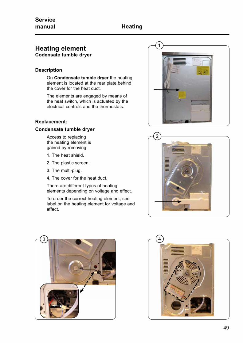
1Heating elementCodensate tumble dryer
Description On Condensate tumble dryer the heating element is located at the rear plate behind the cover for the heat duct .
The elements are engaged by means of the heat switch, which is actuated by the electrical controls and the thermostats .
Replacement:Condensate tumble dryer
Access to replacing the heating element is gained by removing:
1 . The heat shield .
2 . The plastic screen .
3 . The multi-plug .
4 . The cover for the heat duct .
There are different types of heating elements depending on voltage and effect .
To order the correct heating element, see label on the heating element for voltage and effect .
2
3 4

50

51
Drum with bearingServicemanual
Content
Dismounting drum . Replacing support rollers or bearing . . . . . . . . . . . 54

Drum with bearingServicemanual
52
Description:The drum is suspended at the back in a bearing mounted in the rear plate .
At the front the drum rests on two bearing rollers . See the section "Diassembling the dryer" .
Replacement:Replacement of rear bearing (bearing housing) can be done without disassembling the tumble dryer, fig . 1 .
Standard dryer .1 . Dismount the heat shield .
2 . Unscrew the back cover A .
3 . Loosen the drive belt on the drum from the motor .
4 . Unscrew the three screws B and the nut on drum shaft and take out the bearing and replace it with the new bearing .
Condensate dryer1 . Dismount the heat shield, fig . 2 .
2 . Dismount the plastic cover and unplug the plug to the fan motor .
3 . Loosen the drive belt on the drum from the motor .
4 . Unscrew the three screws B and the nut on drum shaft and take out the bearing and replace it with the new bearing, fig . 1 .
1
2
A
B

53
Drum with bearingServicemanual
Replacement:
Replacement of rollers:
1 . Dismount the back plate and take out the drum, see section for "disassembling the dryer" . 2 . Unscrew the four screws at the front of the dryer, fig . 1 . 3 . Remove the flange from the rear side of the door opening, fig . 2 . 4 . Replace the new roller by pulling the damaged roller out and pressing the new roller in place, fig . 3 .
Note! The two locking pins, has to be disengaged, fig . 4 .
1
2
43
Rollers
Pins

54

55
Cabinet, door reversalServicemanual
Contents
Reversing door . . . . . . . . . . . . . . . . . . . . . . . . . . . . . . . . . . . . . . . . . . . 58
Cabinet, door reversalServicemanual
56
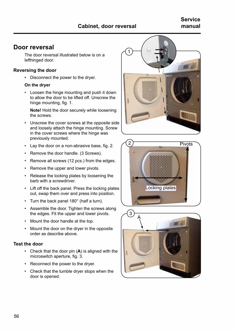
Door reversalThe door reversal illustrated below is on a lefthinged door .
Reversing the door• Disconnect the power to the dryer.
On the dryer
• Loosen the hinge mounting and push it down to allow the door to be lifted off . Unscrew the hinge mounting, fig. 1.
Note! Hold the door securely while loosening the screws .
• Unscrew the cover screws at the opposite side and loosely attach the hinge mounting . Screw in the cover screws where the hinge was previously mounted .
• Lay the door on a non-abrasive base, fig. 2.
• Remove the door handle. (3 Screws).
• Remove all screws (12 pcs.) from the edges.
• Remove the upper and lower pivots.
• Release the locking plates by loosening the barb with a screwdriver .
• Lift off the back panel. Press the locking plates out, swap them over and press into position .
• Turn the back panel 180° (half a turn).
• Assemble the door. Tighten the screws along the edges . Fit the upper and lower pivots .
• Mount the door handle at the top.
• Mount the door on the dryer in the opposite order as describe above .
Test the door• Check that the door pin (A) is aligned with the
microswitch aperture, fig. 3.
• Reconnect the power to the dryer.
• Check that the tumble dryer stops when the door is opened .
A
1
2
3
Pivots
Locking plates
57
RMCServicemanual
Content
RMC general . . . . . . . . . . . . . . . . . . . . . . . . . . . . . . . . . . . . . . . . . . . . . . 60

A
RMCServicemanual
58
1 2
Electrodes for moisture registration Description
The electrodes A and B (2 carbon brushes) are located just underneath the top plate.
Because of the spring-load feature, the two electrodes are in constant touch with the front and rear parts of the drum .
Note! If the drum is to be replaced, the sliding spots where the electrodes touch the drum must be sanded with fine-grained sanding paper to make these spots completely clean and smooth .
Replacement A • Remove the top plate.
• Remove the spade-shaped connector, fig. 1.
• Open the lock.
• Pull out the electrode (the carbon brush).
Replacement B• Dismount top plate.
• Dismount back cover, see section "Disassembling the dryer" .• Dismount spade-shaped connector, fig. 2.
• Unscrew the two screws (C) at the carbon brush house on the back plate .
• Disengage the carbon brush house, dismount the cover in the house and pull out the carbon.
B
C
A


Electrolux Laundry Systems Sweden AB 341 80 Ljungby, Sweden
www.electrolux.com/laundrysystems
Share more of our thinking at www.electrolux.com