Embed Size (px)
Citation preview

AIR CONDITIONER
Wall mounted type
SERVICE MANUAL
INDOOR
ASUG09LZASASUG12LZASASUG15LZAS
OUTDOORAOUG09LZAS1AOUG12LZAS1AOUG15LZAS1
SR_AS024EF_012020.12.20

Notices:• Product specifications and design are subject to change without notice for future improvement.• For further details, please check with our authorized dealer.
Trademarks
FGLair™ is trademark of Fujitsu General Limited in the United States, other countries or both.
Google Play™ is trademark of Google Inc.
App Store® is a service mark of Apple Inc., registered in the U.S. and other countries.
Copyright © 2019 Fujitsu General Limited. All rights reserved.

CONTENTS
1. GENERAL INFORMATION
2. TECHNICAL DATA AND PARTS LIST


1. GENERAL INFORMATION
2019.12.20SR_CH01_AS024EF_01

CONTENTS
1. GENERAL INFORMATION 1. Specifications..............................................................................................01-1
1-1. Indoor unit ......................................................................................................................01-11-2. Outdoor unit....................................................................................................................01-3
2. Dimensions..................................................................................................01-42-1. Indoor unit ......................................................................................................................01-42-2. Outdoor unit....................................................................................................................01-6

1. Specifications
1-1. Indoor unitType
Wall mounted
Inverter heat pump
Model name ASUG09LZAS ASUG12LZAS ASUG15LZASPower supply 208/230 V ~ 60 HzPower supply intake Outdoor unitAvailable voltage range 187—253 V
Capacity
CoolingRated
kW 2.64 3.52 4.25Btu/h 9,000 12,000 14,500
Min.—Max.kW 0.91—3.52 0.91—3.99 0.91—5.39
Btu/h 3,100—12,000 3,100—13,600 3,100—18,400
HeatingRated
kW 3.52 4.69 5.28Btu/h 12,000 16,000 18,000
Min.—Max.kW 0.91—6.45 0.91—6.48 0.91—7.00
Btu/h 3,100—22,000 3,100—22,100 3,100—23,900
Heating(17 °F)*1
RatedkW 2.17 2.93 3.28
Btu/h 7,400 10,000 11,200
Max.kW 4.69 5.13 6.30
Btu/h 16,000 17,500 21,500
Input power
CoolingRated
kW
0.50 0.79 1.04Min.—Max. 0.11—0.85 0.11—0.99 0.15—1.56
HeatingRated 0.66 1.01 1.15Min.—Max. 0.17—1.93 0.17—1.94 0.15—2.19
Heating(17 °F)*1
Rated 0.60 0.88 1.01Max. 2.06 2.06 2.59
CurrentCooling
Rated A2.5 3.8 4.8
Heating 3.3 4.7 5.2
EER CoolingkW/kW 5.28 4.46 4.09Btu/hW 18.0 15.2 13.9
COP HeatingkW/kW 5.33 4.64 4.59Btu/hW 18.2 15.8 15.7
SEER Cooling Btu/hW 33.1 29.4 25.3HSPF Heating Btu/hW 14.2 14.0 13.4
Power factorCooling
%87 90 94
Heating 87 93 96Moisture removal pints/h (L/h) 2.5 (1.2) 2.7 (1.3) 4.0 (1.9)
Maximum operating current*2 CoolingA
9.4 9.4 9.9Heating 10.9 10.9 13.4
FanAirflow rate
Cooling
HIGH
CFM (m3/h)
542 (920) 542 (920) 583 (990)MED 406 (690) 406 (690) 459 (780)LOW 312 (530) 312 (530) 312 (530)QUIET 206 (350) 206 (350) 241 (410)
Heating
HIGH 542 (920) 542 (920) 600 (1,020)MED 406 (690) 406 (690) 459 (780)LOW 312 (530) 312 (530) 312 (530)QUIET 206 (350) 206 (350) 241 (410)
Type × Q'ty Crossflow fan × 1Motor output W 59
Sound pressure level*3
Cooling
HIGH
dB (A)
43 43 45MED 37 37 40LOW 31 31 32QUIET 23 23 26
Heating
HIGH 43 43 45MED 36 36 39LOW 31 31 32QUIET 23 23 26
Heat exchanger type
Dimensions (H × W × D) in (mm)
Main1: 8-1/4 × 31-7/16 × 1-1/16 (210 × 798 × 26.6)Main2: 5-5/16 × 31-7/16 × 13/16 (135 × 798 × 20.0)
Sub1: 3-5/16 × 31-7/16 × 1/2 (84 × 798 × 13.3)Sub2: 3-5/16 × 31-7/16 × 1/2 (84 × 798 × 13.3)
Fin pitch FPI
Man1: 21Main2: 23Sub1: 18Sub2: 18
Rows × Stages
Main1: 2 × 10Main2: 2 × 8Sub1: 1 × 4Sub1: 1 × 4
Pipe type CopperFin type Aluminum
EnclosureMaterial Polystyrene
ColorWhite
Approximate color of Munsell N 9.25/Dimensions(H × W × D)
Netin (mm)
11 × 38-9/16 × 9-7/16 (280 × 980 × 240)Gross 12-11/16 × 42-7/16 × 13-5/8 (322 × 1,078 × 346)
WeightNet
lb (kg)29 (13)
Gross 37 (17)
Connection pipeSize
Liquidin (mm)
Ø 1/4 (6.35)Gas Ø 3/8 (Ø 9.52) Ø 1/2 (Ø 12.7)
Method Flare
Drain hoseMaterial PP+LLDPETip diameter in (mm) Ø17/32 (Ø 13.8) (I.D.), Ø5/8 to 21/32 (Ø 15.8 to 16.7) (O.D.)
Operation rangeCooling
°F (°C) 64 to 90 (18 to 32)%RH 80 or less
Heating °F (°C) 60 to 86 (16 to 30)Remote controller type Wireless (Wired, Mobile app*4 [FGLair™] [option])
1-1. Indoor unit - (01-1) - 1. Specifications
GEN
ERA
LIN
FOR
MA
TIO
N
GEN
ERA
LIN
FOR
MA
TIO
N

TypeWall mounted
Inverter heat pump
Model name ASUG09LZAS ASUG12LZAS ASUG15LZAS
NOTES:• Specifications are based on the following conditions:
– Cooling: Indoor temperature of 80 °FDB (26.67 °CDB) /67 °FWB (19.44 °CWB), and outdoor temperature of 95 °FDB (35 °CDB) / 75 °FWB (23.9 °CWB).– Heating: Indoor temperature of 70 °FDB (21.11 °CDB) /59 °FWB (15.56 °CWB), and outdoor temperature of 47 °FDB (8.33 °CDB) /43 °FWB (6.11 °CWB).– *1: Heating (17 °F): Indoor temperature of 70 °FDB (21.11 °CDB) /60 °FWB (15.56 °CWB), and outdoor temperature of 17 °FDB (-8.33 °CDB) /15 °FWB (-9.44 °CWB).– Pipe length: 25 ft (7.5 m), Height difference: 0 ft (0 m). (Between outdoor unit and indoor unit.)
• Protective function might work when using it outside the operation range.• *2: Maximum current is maximum value when operated within the operation range.• *3: Sound pressure level:
– Measured values in manufacturer’s anechoic chamber.– Because of the surrounding sound environment, the sound levels measured in actual installation conditions might be higher than the specified values here.
• *4: Available on Google Play™ store or on App Store®. Optional WLAN adapter is also required. For details, refer to the setting manual.
1-1. Indoor unit - (01-2) - 1. Specifications
GEN
ERA
LIN
FOR
MA
TIO
N
GEN
ERA
LIN
FOR
MA
TIO
N

1-2. Outdoor unitType Inverter heat pump
Model name AOUG09LZAS1 AOUG12LZAS1 AOUG15LZAS1Power supply 208/230 V ~ 60 Hz
Power supply intake Outdoor unitAvailable voltage range 187—253 VStarting current A 3.3 4.7 5.2
FanAirflow rate
CoolingCFM (m3/h)
1,089 (1,850) 1,171 (1,990) 1,218 (2,070)Heating 1,089 (1,850) 1,089 (1,850) 1,348 (2,290)
Type × Q'ty Propeller fan × 1Motor output W 49
Sound pressure level *1Cooling
dB (A)46 47 49
Heating 47 47 50
Heat exchanger type
Dimensions(H × W × D)
in (mm)Main1: 23-1/8 × 34-11/16 × 11/16 (588 × 881 × 18.19)
Main2: 23-1/8 ×33-1/2 × 11/16 (588 × 851 × 18.19)Fin pitch FPI 20
Rows × StagesMain1: 1 × 28Main2: 1 × 28
Pipe type Copper
Fin typeType (Material) AluminumSurface treatment PC fin
CompressorType DC rotaryMotor output W 900 1,030
RefrigerantType R410A
Chargelb oz 2 lb 14 oz 2 lb 16 oz
g 1,300 1,350
Refrigerant oilType RB68Amount in3 (cm3) 24.4 (400)
EnclosureMaterial Steel sheet
ColorBeige
Approximate color of Munsell 10YR 7.5/1.0Dimensions(H × W × D)
Netin (mm)
24-7/8 × 31-7/16 × 11-7/16 (632 × 799 × 290)Gross 27-1/4 × 37 × 14-3/4 (692 × 940 × 375)
WeightNet
lb (kg)84 (38) 86 (39)
Gross 95 (43)
Connection pipe
SizeLiquid
in (mm)Ø 1/4 (Ø 6.35)
Gas Ø 3/8 (Ø 9.52) Ø 1/2 (Ø 12.7)Method FlarePre-charge length
ft (m)49 (15)
Max. length 66 (20)Max. height difference 49 (15)
Operation rangeCooling
°F (°C)14 to 115 (-10 to 46)
Heating -6 to 75 (-21 to 24)
Drain hoseMaterial LDPETip diameter in (mm) Ø 1/2 (Ø 13.0) (I. D.), Ø 5/8 to 11/16 (Ø 16.0 to 16.8) (O. D.)
NOTES:• Specifications are based on the following conditions:
– Cooling: Indoor temperature of 80 °FDB (26.67 °CDB) / 67 °FWB (19.44 °CWB), and outdoor temperature of 95 °FDB (35 °CDB) / 75 °FWB (23.9 °CWB).– Heating: Indoor temperature of 70 °FDB (21.11 °CDB) / 59 °FWB (15 °CWB), and outdoor temperature of 47 °FDB (8.33 °CDB) / 43 °FWB (6.11 °CWB).– Pipe length: 24 ft 6 in (7.5 m), Height difference: 0 ft (0 m). (Between outdoor unit and indoor unit.)
• Protective function might work when using it outside the operation range.• *1: Sound pressure level
– Measured values in manufacturer’s anechoic chamber.– Because of the surrounding sound environment, the sound levels measured in actual installation conditions might be higher than the specified values here.
1-2. Outdoor unit - (01-3) - 1. Specifications
GEN
ERA
LIN
FOR
MA
TIO
N
GEN
ERA
LIN
FOR
MA
TIO
N

2. Dimensions
2-1. Indoor unit¢ Models: ASUG09LZAS, ASUG12LZAS, and ASUG15LZAS
Unit: in (mm)
38-9/16 (980) 9-7/16 (240)
11
(2
80
)
Outline of indoor unit
1-7
/16
(3
7)
1-7
/16
(3
7)
15-3/4 (400) 3-9/16
(90)
16-1/4 (413)3-1/16
(77)
2-7/8
(73)
16-7/16 (417)2-3/8
(61)
16-7/8 (429)
4-1/2 (115)2-13/16 (72)
for pipe inlet Ø 2-9/16 (65)
for pipe inlet Ø 2-9/16 (65)
2-1. Indoor unit - (01-4) - 2. Dimensions
GEN
ERA
LIN
FOR
MA
TIO
N
GEN
ERA
LIN
FOR
MA
TIO
N

Installation space requirementProvide sufficient installation space for product safety.
Unit: in (mm)
Wall hook bracket
Outline of the indoor unit
2 (
50
) o
r m
ore
3 (
71
) o
r m
ore
2 (40) or more 3 (70) or more
5 (117) or more
60 (1,500) or more
71
(1
,80
0)
or
mo
re
7 (160) or more
2-1. Indoor unit - (01-5) - 2. Dimensions
GEN
ERA
LIN
FOR
MA
TIO
N
GEN
ERA
LIN
FOR
MA
TIO
N

2-2. Outdoor unit¢ Models: AOUG09LZAS1, AOUG12LZAS1, and AOUG15LZAS1
Side viewSide view Front view
Top view
22-13/16 (580)
31-7/16 (799)3/4 (19) 2-11/16 (68) 1/2 (13) 11-7/16 (290)
1-5/16 (33) 1-3/16 (30)
4-5/16 (109)
13
-7/8
(3
53
)2
4-7
/8 (
63
2)
13
/16
(2
0)
13
(3
30
)
Pitch
of b
olts
for
insta
llatio
n
Pitch of bolts for installation
4-M10 hole
Unit: in (mm)
Side view (Valve part)
4-3
/4 (
12
0)
4-1
/4 (
18
4)
7-1/16 (180)
Bottom view
Airflow
Drain port Ø1-5/8 (42)
1-7
/16
(3
7)
15-11/16 (399)
Hole
Hole
Hole
2-2. Outdoor unit - (01-6) - 2. Dimensions
GEN
ERA
LIN
FOR
MA
TIO
N
GEN
ERA
LIN
FOR
MA
TIO
N

2. TECHNICAL DATA AND PARTS LIST
2019.12.20SR_CH02_AS024EF_01

CONTENTS
2. TECHNICAL DATA AND PARTS LIST 1. Precautions..................................................................................................02-1 2. Indoor unit parts list....................................................................................02-2
2-1. Models: ASUG09LZAS, ASUG12LZAS, and ASUG15LZAS..........................................02-2
3. Outdoor unit parts list.................................................................................02-63-1. Models: AOUG09LZAS1, AOUG12LZAS1, and AOUG15LZAS1...................................02-6
4. Accessories ...............................................................................................02-104-1. Indoor unit ....................................................................................................................02-104-2. Outdoor unit..................................................................................................................02-10
5. Optional parts ...........................................................................................02-115-1. Indoor unit ....................................................................................................................02-11
6. Refrigerant system diagrams...................................................................02-136-1. Models: AOUG09LZAS1, AOUG12LZAS1, and AOUG15LZAS1.................................02-13
7. Wiring diagrams ........................................................................................02-147-1. Indoor unit ....................................................................................................................02-147-2. Outdoor unit..................................................................................................................02-15
8. PC board diagrams ...................................................................................02-168-1. Models: ASUG09LZAS, ASUG12LZAS, and ASUG15LZAS........................................02-168-2. Models: AOUG09LZAS1, AOUG12LZAS1, and AOUG15LZAS1.................................02-17

1. PrecautionsWhen you start servicing, pay attention to the following points. For detailed precautions, refer to theinstallation manual of the products.
CAUTION• Service personnel
– Any person who is involved with working on or breaking into a refrigerant circuit should hold acurrent valid certificate from an industry-accredited assessment authority, which authorizestheir competence to handle refrigerants safely in accordance with an industry recognized as-sessment specification.
– Servicing shall only be performed as recommended by the equipment manufacturer. Mainte-nance and repair requiring the assistance of other skilled personnel shall be carried out underthe supervision of the person competent in the use of flammable refrigerants.
– Servicing shall be performed only as recommended by the manufacturer.• Work
– Work in confined spaces shall be avoided.– The area around the workspace shall be sectioned off.– Electric shock may occur. After turning off the power, always wait 5 minutes before touching
electrical components.– Do not touch the fins of the heat exchanger. Touching the heat exchanger fins could result in
damage to the fins or personal injury such as skin rupture.– Do not place any other electrical products or household belongings under the product.– Condensation dripping from the product might get them wet, and may cause damage or mal-
function to the property.
• Service parts information and design are subject to change without notice for product improve-ment.
• For the latest information of the service parts, refer to our Service Portal.https://fujitsu-general.force.com/portal/
• Precise figure of the service parts listed in this manual may differ from the actual service parts.
- (02-1) - 1. Precautions
TEC
HN
ICA
L D
ATA
AN
D P
AR
TS L
IST
TEC
HN
ICA
L D
ATA
AN
D P
AR
TS L
IST

2. Indoor unit parts list
2-1. Models: ASUG09LZAS, ASUG12LZAS, and ASUG15LZAS¢ Exterior parts and Accessories
1
2
2
4
7
8
10
11
12
13
14
1518
17
19 20
a
b
c
d
15
16
8
9
3
5
6
2-1. Models: ASUG09LZAS, ASUG12LZAS, and ASUG15LZAS - (02-2) - 2. Indoor unit parts list
TEC
HN
ICA
L D
ATA
AN
D P
AR
TS L
IST
TEC
HN
ICA
L D
ATA
AN
D P
AR
TS L
IST

Item no. Part no. Part name Service part1 9323351004 Bracket panel ♦2 9387476002 Screw cap ♦3 9313951047 Conduit holder ♦4 9387597035 Wire cover assy ♦5 9383765032 Wifi holder assy ♦6 9383634017 Wireless LAN adapter ♦7 9387479010 U/D louver assy ♦8 9332911008 Electric filter holder ♦9 9323341005 Under cover L ♦
10 9317250009 Air clean filter assy ♦11 9332438765 Remote controller ♦12 9318912005 Remote controller holder ♦13 9387596441 Front panel total assy ♦14 9387756210 Intake grille assy ♦15 9323340008 Air filter ♦16 9333719009 Grille clamper L ♦17 9333704005 Grille clamper R ♦18 9323342002 Under cover R ♦19 9383730023 Louver spring ♦20 9333608006 Bush ♦a — Front panel —b — Panel cover —c — Front panel cover —d — Front panel B —
2-1. Models: ASUG09LZAS, ASUG12LZAS, and ASUG15LZAS - (02-3) - 2. Indoor unit parts list
TEC
HN
ICA
L D
ATA
AN
D P
AR
TS L
IST
TEC
HN
ICA
L D
ATA
AN
D P
AR
TS L
IST
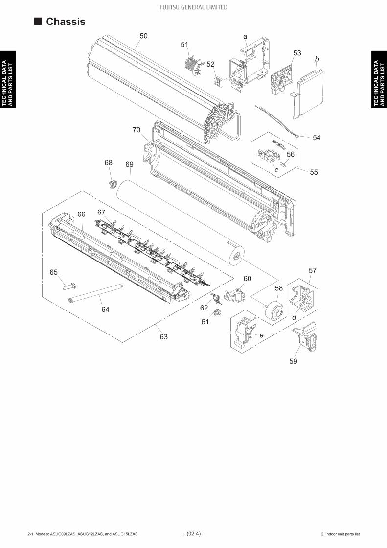
¢ Chassis
70
51
50
69
60
59
61
58
d
e
68
63
62
a
53b
52
54
55
56
57
c
65
64
6766
2-1. Models: ASUG09LZAS, ASUG12LZAS, and ASUG15LZAS - (02-4) - 2. Indoor unit parts list
TEC
HN
ICA
L D
ATA
AN
D P
AR
TS L
IST
TEC
HN
ICA
L D
ATA
AN
D P
AR
TS L
IST

Item no. Part no. Part name Service part
509383735042 Evaporator total assy (for 09-12 model) ♦9383735059 Evaporator total assy (for 15 model) ♦
51 9387467000 Room thermistor holder ♦52 9306489045 Terminal ♦
539711141392 Main PCB (for 09 model) ♦9711141408 Main PCB (for 12 model) ♦9711141415 Main PCB (for 15 model) ♦
54 9900627041 Thermistor assy ♦55 9711146014 Display assy ♦56 9317755061 Pyroelectric sensor ♦57 9387589023 Motor case assy ♦58 9603821005 Brushless motor ♦59 9383565007 Pipe bracket ♦60 9387488043 Cable guide ♦61 9387714012 Gear case assy ♦62 9383728006 R and L louver SPM assy ♦63 9387590036 Drain pan total assy ♦64 9316904002 Drain hose assy ♦65 9316177017 Drain cap ♦66 9387591019 Drain pan assy ♦67 9383727009 Spacer K assy ♦68 9333628004 Bearing D assy ♦69 9387055054 Crossflow fan assy ♦70 9387587029 Base assy ♦a — Control box —b — Control cover —c — Display case —d — Motor case —e — Motor cover assy —
2-1. Models: ASUG09LZAS, ASUG12LZAS, and ASUG15LZAS - (02-5) - 2. Indoor unit parts list
TEC
HN
ICA
L D
ATA
AN
D P
AR
TS L
IST
TEC
HN
ICA
L D
ATA
AN
D P
AR
TS L
IST

3. Outdoor unit parts list
3-1. Models: AOUG09LZAS1, AOUG12LZAS1, andAOUG15LZAS1
¢ Exterior parts and chassis
14
15
9
a
1016
18
19
21
22
20
8
1
2
65
1311
12
b
4
17
3
7
3-1. Models: AOUG09LZAS1, AOUG12LZAS1, and AOUG15LZAS1 - (02-6) - 3. Outdoor unit parts list
TEC
HN
ICA
L D
ATA
AN
D P
AR
TS L
IST
TEC
HN
ICA
L D
ATA
AN
D P
AR
TS L
IST

Item no. Part no. Part name Service part1 9322556028 Top panel assy ♦2 9377854001 Protective net assy ♦3 9322327000 Thermistor holder ♦4 9322552242 Cabinet right assy ♦5 9384276001 Conduit cover ♦6 9322570062 Switch cover assy ♦7 9383720000 Drain cap assy ♦8 9323550025 Base assy ♦9 9322144003 Drain pipe ♦
109710802416 Main PCB (for 09 model) ♦9710802423 Main PCB (for 12 model) ♦9710802461 Main PCB (for 15 model) ♦
11 9900935054 Thermistor assy ♦12 9900985011 Thermistor assy (Compressor temp.) ♦13 9900565060 Thermistor assy (Outdoor temp.) ♦14 9322420039 Heat sink ♦15 9810028006 Thermistor stopper ♦16 9317903011 Emblem ♦17 9384273000 Fan Guard ♦18 9322555182 Front panel assy ♦19 9322150004 Propeller fan ♦20 9603601003 Brushless motor ♦21 9322553027 Motor bracket assy ♦
229317089616 Condenser total assy (for 09-12 model) ♦9317089654 Condenser total assy (for 15 model) ♦
a — Inverter assy —b — Hair pin cushion —
3-1. Models: AOUG09LZAS1, AOUG12LZAS1, and AOUG15LZAS1 - (02-7) - 3. Outdoor unit parts list
TEC
HN
ICA
L D
ATA
AN
D P
AR
TS L
IST
TEC
HN
ICA
L D
ATA
AN
D P
AR
TS L
IST

¢ Compressor
A
A
B
B
50
51
52
53
54
55
56
5758596061
a
b
3-1. Models: AOUG09LZAS1, AOUG12LZAS1, and AOUG15LZAS1 - (02-8) - 3. Outdoor unit parts list
TEC
HN
ICA
L D
ATA
AN
D P
AR
TS L
IST
TEC
HN
ICA
L D
ATA
AN
D P
AR
TS L
IST

Item no. Part no. Part name Service part
509810542007 Compressor (for 09-12 model) ♦9810541000 Compressor (for 15 model) ♦
51 9322446015 4-way valve assy ♦52 9970194023 Solenoid ♦53 9970173028 Expansion valve coil ♦54 9322463029 Pulse motor valve assy ♦55 9322474001 2-way valve assy ♦
569322850010 3-way valve assy (for 09-12 model) ♦9387831016 3-way valve assy (for 15 model) ♦
57 9322824004 S-insulator K ♦58 9323045002 S-insulator V ♦59 9322501004 S-insulator H ♦60 9322847003 S-insulator F ♦61 9322503008 S-insulator B ♦a — Valve bracket —b — Muffler —
3-1. Models: AOUG09LZAS1, AOUG12LZAS1, and AOUG15LZAS1 - (02-9) - 3. Outdoor unit parts list
TEC
HN
ICA
L D
ATA
AN
D P
AR
TS L
IST
TEC
HN
ICA
L D
ATA
AN
D P
AR
TS L
IST

4. Accessories
4-1. Indoor unit¢ Models: ASUG09LZAS, ASUG12LZAS, and ASUG15LZAS
Part name Exterior Q’ty Part name Exterior Q’ty
Operating manual 1 Tapping screw (large) 5
Installation manual 1 Tapping screw (small) 2
Remote controller 1 Battery 2
Remote controllerholder 1 Filter holder 2
Cloth tape 1 Air cleaning filters 1
Wall hook bracket 1
4-2. Outdoor unit¢ Models: AOUG09LZAS1, AOUG12LZAS1, and AOUG15LZAS1
Part name Exterior Q’ty Part name Exterior Q’ty
Installation manual 1 Cable tie 2
Drain pipe 1 Drain cap 5
4-1. Indoor unit - (02-10) - 4. Accessories
TEC
HN
ICA
L D
ATA
AN
D P
AR
TS L
IST
TEC
HN
ICA
L D
ATA
AN
D P
AR
TS L
IST

5. Optional parts
5-1. Indoor unit¢ Controllers
Exterior Part name Model name Summary
76°F
80°F
74°F
84°F
68°FAway
CustomAuto Auto
Cool
Heat
Office
Set Temp.Mode
MenuStatusVacation
Fan
Fri 10:00AM
Room Temp.Cool
Heat
Wired remotecontroller UTY-RNRUZ*
Easy finger touch operation with LCDpanel. Backlit LCD enables easyoperation in a dark room.Wire type: Non-polar 2-wireOptional communication kit isnecessary for installation.NOTE: When this remote controller
is connected, wirelessremote controller cannot beused.
76°F
80°F
74°F
84°F
68°FAway
CustomAuto Auto
Cool
Heat
Office
Set Temp.Mode
MenuStatusVacation
Fan
Fri 10:00AM
Room Temp.Cool
Heat
Simple remotecontroller UTY-RSRY
Compact remote controllerconcentrates on the basic functionssuch as Start/Stop, fan control,temperature setting, and operationmode.Wire type: Non-polar 2-wireOptional communication kit isnecessary for installation.
Simple remotecontroller UTY-RHRY
Compact remote controllerconcentrates on the basic functionssuch as Start/Stop, fan control, andtemperature setting.Wire type: Non-polar 2-wireOptional communication kit isnecessary for installation.
NOTES:• Available functions may differ by the remote controller. For details, refer to the operation manu-
al.• When using a Wireless LAN adapter, group controlling system of the wired remote controller is
prohibited.
5-1. Indoor unit - (02-11) - 5. Optional parts
TEC
HN
ICA
L D
ATA
AN
D P
AR
TS L
IST
TEC
HN
ICA
L D
ATA
AN
D P
AR
TS L
IST

¢ Others
Exterior Part name Model name Summary
Externalconnect kit UTY-XWZXZ5
Required when external device isconnected.
External inputand output PCB UTY-XCSXZ2
Use to connect with external devicesand air conditioner PCB.Optional External connect kit isnecessary for installation.
Communicationkit UTY-TWRXZ2 Use to connect Non-polar 2-core wired
remote controller.
5-1. Indoor unit - (02-12) - 5. Optional parts
TEC
HN
ICA
L D
ATA
AN
D P
AR
TS L
IST
TEC
HN
ICA
L D
ATA
AN
D P
AR
TS L
IST

6. Refrigerant system diagrams
6-1. Models: AOUG09LZAS1, AOUG12LZAS1, andAOUG15LZAS1
Strainer
Strainer
3-way valve
2-way valve
Muffler
4-way valve
Expansion valve
Heat exchanger
Heat exchanger
(INDOOR)
(OUTDOOR)
Co
mp
resso
r
Cooling
Heating
ThD
ThR
ThO
ThHO
Muffler
Accumulator
ThPI
ThC
: Thermistor (Discharge temperature)
: Thermistor (Outdoor temperature)
: Thermistor (Heat exchanger out temperature)
ThD
: Thermistor (Compressor temperature)ThC
ThO
ThHO
: Thermistor (Room temperature)
: Thermistor (Pipe temperature)
ThR
ThPI
6-1. Models: AOUG09LZAS1, AOUG12LZAS1, and AOUG15LZAS1 - (02-13) - 6. Refrigerant system diagrams
TEC
HN
ICA
L D
ATA
AN
D P
AR
TS L
IST
TEC
HN
ICA
L D
ATA
AN
D P
AR
TS L
IST

7. Wiring diagrams
7-1. Indoor unit¢ Models: ASUG09LZAS, ASUG12LZAS, and ASUG15LZAS
7-1. Indoor unit - (02-14) - 7. Wiring diagrams
TEC
HN
ICA
L D
ATA
AN
D P
AR
TS L
IST
TEC
HN
ICA
L D
ATA
AN
D P
AR
TS L
IST

7-2. Outdoor unit¢ Models: AOUG09LZAS1, AOUG12LZAS1, and AOUG15LZAS1
7-2. Outdoor unit - (02-15) - 7. Wiring diagrams
TEC
HN
ICA
L D
ATA
AN
D P
AR
TS L
IST
TEC
HN
ICA
L D
ATA
AN
D P
AR
TS L
IST
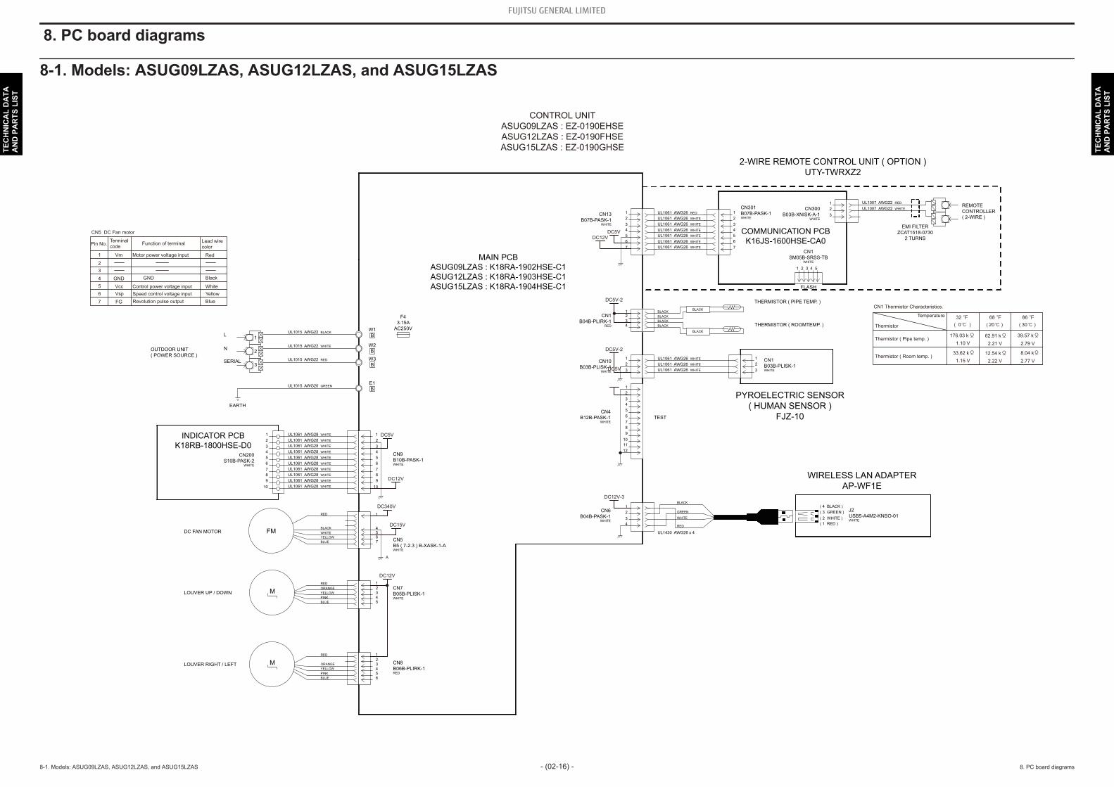
8. PC board diagrams
8-1. Models: ASUG09LZAS, ASUG12LZAS, and ASUG15LZAS
UL1061 AWG28 WHITE
UL1061 AWG28 WHITE
UL1061 AWG28 WHITE
UL1061 AWG28 WHITE
UL1061 AWG28 WHITE
UL1061 AWG28 WHITE
UL1061 AWG28 WHITE
UL1061 AWG28 WHITE
UL1061 AWG28 WHITE
UL1061 AWG28 WHITE
UL1015 AWG20 GREEN
UL1015 AWG22 RED
UL1015 AWG22 WHITE
UL1015 AWG22 BLACK
RED
WHITE
BLACK
YELLOW
BLUE
RED
ORANGE
YELLOW
PINK
BLUE
RED
ORANGE
YELLOW
PINK
BLUE
BLACK
BLACK
BLACK
BLACK
BLACK
UL1061 AWG26 WHITE
BLACK
UL1061 AWG26 WHITE
UL1061 AWG26 WHITE
UL1061 AWG26 WHITE
UL1061 AWG26 RED
UL1061 AWG26 WHITE
UL1061 AWG26 WHITE
UL1061 AWG26 WHITE
UL1061 AWG26 WHITE
UL1061 AWG26 WHITE
UL1007 AWG22 WHITE
UL1007 AWG22 RED
UL1430 AWG26 x 4
WHITE
RED
BLACK
GREEN
12
11
10
9
8
7
6
5
4
3
2
1
3
2
1
43
21
7
6
5
4
3
2
1
7
6
5
4
3
2
1
3
2
1
3
2
1
4
3
2
1
( 1 RED )
( 2 WHITE )
( 3 GREEN )
( 4 BLACK )
10
9
8
7
6
5
4
3
2
1
10
9
8
7
6
5
4
3
2
1
7654
1
5432
1
65432
1
F4
3.15A
AC250VW1
B
W2
B
W3
B
E1
B
EARTH
1
2
3
L
N
SERIAL
CN9
B10B-PASK-1WHITE
CN5
B5 ( 7-2.3 ) B-XASK-1-AWHITE
CN7
B05B-PLISK-1WHITE
CN8
B06B-PLIRK-1RED
CN200
S10B-PASK-2WHITE
CN4
B12B-PASK-1WHITE
CN6
B04B-PASK-1WHITE
CN10
B03B-PLISK-1WHITE
CN1
B04B-PLIRK-1RED
CN13
B07B-PASK-1WHITE
CN301
B07B-PASK-1WHITE
CN300
B03B-XNISK-A-1WHITE
CN1
SM05B-SRSS-TBWHITE
54321
CN1
B03B-PLISK-1WHITE
J2
USB5-A4M2-KNSO-01WHITE
LOUVER UP / DOWN
LOUVER RIGHT / LEFT
DC FAN MOTOR FM
M
M
THERMISTOR ( ROOMTEMP. )
THERMISTOR ( PIPE TEMP. )
2-WIRE REMOTE CONTROL UNIT ( OPTION )
UTY-TWRXZ2
COMMUNICATION PCB
K16JS-1600HSE-CA0
FLASH
EMI FILTER
ZCAT1518-0730
2 TURNS
REMOTE
CONTROLLER
( 2-WIRE )
WIRELESS LAN ADAPTER
AP-WF1E
PYROELECTRIC SENSOR
( HUMAN SENSOR )
FJZ-10TEST
INDICATOR PCB
K18RB-1800HSE-D0
OUTDOOR UNIT
( POWER SOURCE )
MAIN PCB
ASUG09LZAS : K18RA-1902HSE-C1
ASUG12LZAS : K18RA-1903HSE-C1
ASUG15LZAS : K18RA-1904HSE-C1
CONTROL UNIT
ASUG09LZAS : EZ-0190EHSE
ASUG12LZAS : EZ-0190FHSE
ASUG15LZAS : EZ-0190GHSE
DC340V
DC15V
A
DC12V
DC5V
DC12V
DC5V-2
DC12V-3
DC12V
DC5V
DC5V-2
DC5V
CN5 DC Fan motor
1
3
4
5
6
7
Pin No.Terminal
code
Vm
GND
Vcc
Vsp
FG
Function of terminal
Revolution pulse output
Speed control voltage input
Control power voltage input
GND
Motor power voltage input
Lead wire
color
Red
Black
White
Yellow
Blue
2
CN1 Thermistor Characteristics.
Thermistor
Thermistor ( Pipe temp. )176.03 k 62.91 k 39.57 k
1.10 V 2.21 V 2.79 V
Thermistor ( Room temp. )33.62 k 12.54 k 8.04 k
1.15 V 2.22 V 2.77 V
Temperature
( 20 ) ( 30 )( 0 )
32 68 86
8-1. Models: ASUG09LZAS, ASUG12LZAS, and ASUG15LZAS - (02-16) - 8. PC board diagrams
TEC
HN
ICA
L D
ATA
AN
D P
AR
TS L
IST
TEC
HN
ICA
L D
ATA
AN
D P
AR
TS L
IST

8-2. Models: AOUG09LZAS1, AOUG12LZAS1, and AOUG15LZAS1
W103
B
W104
B
W70
B
W100
B
W101
B
W102
B
1
2
3
4
1
2
3
1
2
3
W400
B
U
W401
B
V
W402
B
W
12
11
10
9
8
7
6
5
4
3
2
1
3
1
5
4
3
2
1
5
4
1
7
6
2
1
3
1
UL3271 AWG16RED
UL3271 AWG16WHITE
UL3271 AWG16BLACK
RED
BLACK
WHITE
BLUE
RED
RED
BLACK
WHITE
YELLOW
RROWN
RED
BLUE
ORANGE
YELLOW
WHITE
WHITE
BLACK
BLACK
BLACK
UL1015 AWG20BLACK
UL1015 AWG20WHITE
UL1015 AWG20RED
UL1015 AWG14BLACK
UL1015 AWG14WHITE
UL1015 AWG16GREEN
BLACK
BLACK
BLACK
BLACK
BLACK
BLACK
BLACK
BLACK
P1
B04B-PLIRK-1RED
P5
B03B-PLISK-1WHITE
P15
B03B-PASK-1WHITE
P60
B2P3-VH-BWHITE
P650
B5 ( 7-2.3 ) B-XASK-1-AWHITE
P30
B05B-PLISK-1WHITE
P50
B2P ( 4-2.4 ) -VH-B-CBLACK
P600
B12B-PASK-1WHITE
TRCB-25-15-12
7 TURNS
WIRE w/TERMINAL ( CORE )
1015#GREENTERMINAL
HP-T3036B-2-6P-A1
FRAME FRAME
SLR-03VF
FM
M
CM1
2
3
L
N
L
N
SERIAL
TO INDOOR UNIT
POWER SOURCE
AC208/230V
60Hz
EARTH
THERMISTOR ( PIPE TEMP. )
THERMISTOR ( DISCHARGE TEMP. )
THERMISTOR ( OUTDOOR TEMP. )
THERMISTOR ( COMPRESSOR TEMP. )
TEST
BASE HEATER
AC230V 150W
EXPANSION VALVE COIL
DC FAN MOTOR
COMPRESSOR
4-WAY VALVE COIL
DC Resistance 1970 (20 )
U-V
V-W
U-W
Winding Resistance
1.916
1(Red) - 3(Blue)
1(Red) - 4(Orange)
1(Red) - 5(Yellow)
1(Red) - 6(White)
P30 Expansion Valve Coil
46.0
Recommended Drive Condition
Unipolar Drive, 1-2 Phase Excitation.
Coil resistance
1
3
4
5
6
Pin No.Terminal
code
Vm
GND
Vcc
Vsp
FG
Function of terminal
Revolution pulse output
Speed control voltage input
Control power voltage input
GND
Motor power voltage input
Lead wire
color
Red
Black
White
Yellow
Brown
2
7
P650 DC Fan Motor
AC
AC208/230V
( ON )
AC208/230V
( ON )
DC5V
Thermistor ( Discharge temp. )168.60 k 62.55 k 40.01 k
0.36 V 0.86 V 1.23 V
Thermistor ( Outdoor temp. )35.21 k 12.64 k 7.97 k
2.61 V 3.76 V 4.14 V
Thermistor ( Pipe temp. )16.05 k 5.98 k 3.84 k
1.14 V 2.21 V 2.77 V
Thermistor ( Compressor temp. )168.60 k 62.55 k 40.01 k
0.36 V 0.86 V 1.23 V
( 20 )
68
68
(20 ) 68
P1 Thermistor Characteristics.
Thermistor
Temperature
( 20 ) ( 30 )( 0 )
32 68 86
P5 Thermistor Characteristics.
Thermistor
Temperature
( 20 ) ( 30 )( 0 )
32 68 86
P15 Thermistor Characteristics.
Thermistor
Temperature
( 20 ) ( 30 )( 0 )
32 68 86
DC15V-1
DC5V
DC12VDC12V
DC340V
MAIN PCB
AOUG09LZAS1: K16JG-190CHUE-C1
AOUG12LZAS1: K16JG-190DHUE-C1
AOUG15LZAS1 : K16JG-190GHUE-C1
AOUG09LZAH1: K16JG-190EHUE-C1
AOUG12LZAH1: K16JG-190FHUE-C1
AOUG15LZAH1: K16JG-190HHUE-C1
*AOUG09LZAH1, 12LZAH1 and 15LZAH1 only.
*
INVERTER ASSEMBLY
AOUG09LZAS1 : EZ-0190MHUE
AOUG12LZAS1 : EZ-0190PHUE
AOUG15LZAS1 : EZ-0190THUE
AOUG09LZAH1 : EZ-0190RHUE
AOUG12LZAH1 : EZ-0190SHUE
AOUG15LZAH1 : EZ-0190WHUE
EMI FILTER
KRFC-13
2 TURNS
EMI FILTER
KRFC-13
1 TURN
EMI FILTER
KRFC-13
2 TURNS
8-2. Models: AOUG09LZAS1, AOUG12LZAS1, and AOUG15LZAS1 - (02-17) - 8. PC board diagrams
TEC
HN
ICA
L D
ATA
AN
D P
AR
TS L
IST
TEC
HN
ICA
L D
ATA
AN
D P
AR
TS L
IST