Embed Size (px)
Citation preview

SERVICE MANUAL
SALISBURY 5HA AXLES
WINGET LIMITEDP.O. BOX 41
EDGEFOLD INDUSTRIAL ESTATE PLODDER LANE
BOLTONLANCS
BL4 OLRTEL: ++ 44 (0) 1204 854650 FAX: +
+ 44 (0) 1204 854663 parts@winget .co.uk
WINGET LIMITED CANNOT ASSIST USERS OF EQUIPMENT THAT WAS MANUFACTURED BY OTHER OEM’S
WINGET LIMITED WILL ONLY OFFER PARTS AND SERVICE ASSISTANCE TO USERS OF EQUIPMENT MANUFACTURED BY WINGET LIMITED
PLEASE BE AWARE THAT THE MAJORITY OF THE AXLE COMPONENTS ARE NO LONGER AVAILABLE

Introduction
Winget Limited gratefully acknowledge the assistance given by GKN Salisbury inthe preparation of this manual, however neither Winget Limited or Salisbury canbe held responsible for any errors or omissions.
The procedures described within this manual should enable experienced servicepersonnel to strip, repair and re-build Salisbury 5HA series axles fitted to WingetSite Dumpers in a safe and competent manner. The procedures are not intendedto be used by personnel who are unfamiliar with the product or mechanicallyinexperienced.
It is assumed that personnel are aware of the Health & Safety Regulations whichshould be applied but the following should act as a reminder.
Whenever possible any repairs or service should be carried out in a cleanenvironment. If work must be carried out on site or in the field steps should betaken to ensure that dirt or foreign materials cannot enter the assembly.
Ensure all works tools are in good condition and only use the correct tool for thejob in hand.
Always wear safety spectacles when using soft or hard faced hammers, chisels,drifts or when using air tools. Wear safety spectacles when cleaning componentsor when grinding.
Do not misuse air lines and be aware of the damage compressed air can cause ifmisused.
Always make sure lifting equipment is in good condition and the Safe WorkingLoad exceeds the weight of the component to be lifted.
Always use suitable supports i.e. axle stands or baulks of timber in conjunctionwith hydraulic jacks etc. Never rely on hydraulic jacks alone to support amachine.
Be aware of hot surface temperatures and take care when draining hot oils.Always dispose of waste oils in accordance with local and national regulations.
Whenever possible always disconnect the battery or battery isolator whenworking on the machine to prevent electrical shorts and unauthorised starting.
Refer to the operator's handbook for a guide to the correct sequence forassembling components and sub-assemblies.

Oils, fuels, silicone sealer etc can cause skin diseases if allowed to contaminatethe skin. Always apply barrier creams, wear suitable protective clothing or whencontamination is unavoidable clean the area with soap and water as soon aspossible. Do not use thinners or other solvents to clean skin.
Health & Safety is a matter of common sense. If common sense is appliedcorrectly the risk of accidents can be reduced.
Spares for Salisbury Axles fitted to Winget Equipment can only be obtained fromWinget Limited or one of our authorised distributors and not from GKN Salisbury.
Always quote your machine's serial number and model together with axle serialnumber and model when ordering spare parts.
5HA series axles are designed to operate under arduous conditions andproviding they are regularly and correctly maintained they will provide longtrouble free service.
The contents of this manual although correct at the time of publication, may besubject to alteration by the manufacturers without notice and Winget Limited canaccept no responsibility for any errors or omissions contained within the followingpages. Nor can we accept any liability whatsoever arising from the use of thismanual howsoever caused.
Winget Limited operate a policy of continuous product development. Therefore,some illustrations or text within this publication may differ from your machine.

INDEX
INTRODUCTION
A. CENTRE SUB ASSEMBLIES
A-1 Shim adjusted centre sub-assemblies.A-2 Collapsible Spacer centre sub-assemblies.
B. DIFFERENTIAL ASSEMBLIES
B-1 2 Pin Diff AssemblyB-2 4 Pin Diff Assembly
C. HUB ASSEMBLIES
C-1 Semi Floating HubC-2 Semi Floating Outrigger HubC-3 Fully Floating HubC-4 End Float Adjustment on 05HA OIMPD Hub
D. BRAKES
D-1 Drum BrakesD-2 Disc BrakesD-3 Oil Immersed Brake (05HA)
E. INTENTIONALLY BLANK
F. AXLE SHAFTS
F-1 Semi FloatingF-2 Semi Floating OutriggerF-3 Fully Floating

G. GEAR TOOTH CONTACT
H. TABLES
J. DIAGRAMS

Section A
CENTREHUB ASSEMBLIES
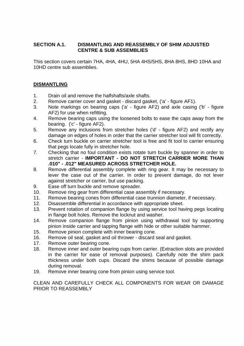
SECTION A.1. DISMANTLING AND REASSEMBLY OF SHIM ADJUSTEDCENTRE & SUB ASSEMBLIES
This section covers certain 7HA, 4HA, 4HU, 5HA 4HS/5HS, 8HA 8HS, 8HD 10HA and10HD centre sub assemblies.
DISMANTLING
1. Drain oil and remove the halfshafts/axle shafts.2. Remove carrier cover and gasket - discard gasket, (‘a’ - figure AF1).3. Note markings on bearing caps ('a' - figure AF2) and axle casing ('b' - figure
AF2) for use when refitting.4. Remove bearing caps using the loosened bolts to ease the caps away from the
bearing. ('c' - figure AF2).5. Remove any inclusions from stretcher holes ('d' - figure AF2) and rectify any
damage on edges of holes in order that the carrier stretcher tool will fit correctly.6. Check turn buckle on carrier stretcher tool is free and fit tool to carrier ensuring
that pegs locate fully in stretcher hole.7. Checking that no foul condition exists rotate turn buckle by spanner in order to
stretch carrier - IMPORTANT - DO NOT STRETCH CARRIER MORE THAN.010" - .012" MEASURED ACROSS STRETCHER HOLE.
8. Remove differential assembly complete with ring gear. It may be necessary tolever the case out of the carrier. In order to prevent damage, do not leveragainst stretcher or carrier, but use packing.
9. Ease off turn buckle and remove spreader.10. Remove ring gear from differential case assembly if necessary.11. Remove bearing cones from differential case trunnion diameter, if necessary.12. Disassemble differential in accordance with appropriate sheet.13. Prevent rotation of companion flange by using service tool having pegs locating
in flange bolt holes. Remove the locknut and washer.14. Remove companion flange from pinion using withdrawal tool by supporting
pinion inside carrier and tapping flange with hide or other suitable hammer.15. Remove pinion complete with inner bearing cone.16. Remove oil seal, gasket and oil thrower - discard seal and gasket.17. Remove outer bearing cone.18. Remove inner and outer bearing cups from carrier. (Extraction slots are provided
in the carrier for ease of removal purposes). Carefully note the shim packthickness under both cups. Discard the shims because of possible damageduring removal.
19. Remove inner bearing cone from pinion using service tool.
CLEAN AND CAREFULLY CHECK ALL COMPONENTS FOR WEAR OR DAMAGEPRIOR TO REASSEMBLY

REASSEMBLY
20. Check that pinion and gear are matched in that the serial no's. on the end faceof the pinion and on the outer diameter of the gears are identical. (It should benoted that marks on the pinion end adjacent to serial number have nosignificance in service.)
21. Assembly inner bearing cone onto pinion using service tool or suitable press.22. Select new shim pack the size of that removed from the inner bearing. Insert into
carrier. Press inner bearing cup into housing, using press and suitable adaptor(if new gear set or bearings are used the shim pack is to be chosen to give thecorrect pinion height setting as described later.)
23. Select new shim pack the size of that removed from the outer bearing. Insertinto carrier. Press outer bearing cup into housing using press and suitableadaptor (if new gear set or bearings are used the shim pack is to be chosen togive a bearing preload as stated in table AT2).
NOTES
a. Ensure both cups are pressed and firmly seated into carrier.b. Take care not to damage face or taper of bearings whilst assembling.c. Both bearing cups may be assembled together if the appropriate service tool
is available.
24. Insert pinion and pinion bearing into housing and support in position.25. Fit outer bearing cone over pinion and seat into cup.26. Fit oil slinger.27. Fit new oil seal gasket and oil seal. The seal is to be fitted with the lip facing
inwards. As an aid to assembly and to prevent lip damage, apply a small amountof grease to lip prior to assembly. The oil seal should be pressed into housingusing a suitable adaptor locating near the outer diameter of the seal.
28. Fit companion flange. If it is necessary to press or tap the flange into position donot let flange react against bearing but react against support on pinion head.
29. Fit washer and new lock nut.30. Before tightening locknut apply a small amount of oil to both bearings.31. Tighten nut gradually to figure given in table AT3 rotating the pinion assembly
slightly at intervals throughout.32. Check the correct positional setting of the pinion is as follows:
a. Check the nominal pinion cone setting distance from table AT1.b. Check the variation figure marked on the head of the pinion (see figure AF3).
This figure is given in thousandths of an inch.c. Add these figures to give the actual required pinion cone setting distance.

Example:
Nominal cone distance = 2.500 2.500Marked variation = (+3) + .003 (-2) - .002Actual required distance = 2.503 2.498
d. Read the differential bearing seat diameter from table AT1.e. Subtract half the figure at 32(d) from that at 32(c) to give nominal clock
setting height.
Example
32(c) = 2.50332(d) = 1.500
--------Clock setting height 1.003
--------
33. Using a small magnetic base clock and setting piece or slipblocks set the clockto the dimension obtained in 32(e). this method of clock setting is shown infigure AF4.
34. Ensure the pinion end is free from burrs.35. Mount the magnetic base of the clock onto the pinion end so that the stylus
registers in the bottom of the differential bearing bore. This is shown in figureAF5. The clock can be moved slightly to and fro by turning the pinion in order toensure maximum reading is obtained.
36. Repeat operation on other differential bearing bore.37. Add the two readings and halve the result in order to obtain the mean figure. If
the pinion is set correctly a mean reading of zero should be obtained. A negativereading indicates the pinion is set too high and shims need to be removed fromunder the inner pinion bearing cup.
A positive reading indicates that the pinion is set too low and more shims needto be added under the inner pinion bearing cup.
NOTES
a. The amount of variation away from zero gives the amount of shimadjustment required.
b. If a change in shim pack is required it is essential that a correspondingopposite change takes place under the outer pinion bearing cup i.e. if .003"is removed from the inner bearing cup shim pack to give the correct pinionheight the .003" must be added to the outer bearing cup shim pack. This is inorder to maintain the correct preload for the two bearings as given in tableAT2.

38. Assemble ring gear onto differential case and bolt together by gradually andevenly tightening the bolts. Do not tighten one bolt at a time but work ondiametrically opposite bolts. This ensures the ring gear is seated correctly on thecase. It is advised to use Loctite 'studlock' grade or similar locking compound onthe bolt treads. Do not use excessively and remove any surplus. Tighten bolts totorque figures given in table AT3.
39. Assemble differential bearing cones to differential case using press and suitableadaptor. NOTE when pressing second bearing cone onto case, seat first bearingcone into its cup in order to prevent damage to bearing case etc.
40. With bearing cups fitted onto cones lower differential case assembly into thecarrier. Take care when meshing gear and pinion not to damage teeth.
41. Position a dial gauge as shown in figure AF6.42. Fit suitable shim packs between the differential bearing cups and carrier on each
side in order to give a reading of .007" on the dial gauge when the gearbacklash is measured. It is important that the pinion is not moved whenmeasuring ring gear backlash otherwise false results are obtained.
The shim packs should be a resistance fit.
Shims are available in .003", .005", .010" and .030"
NOTE
When using new bearings rotate differential assembly approx. six times whilstpressing towards each bearing in turn - this is in order to settle bearings.Following this adjust shim packs if necessary to give resistance fit and repeatbacklash check.
43. Remove differential assembly together with shim packs. Carefully note to whichend the shim pack relates - add .003" shim to each pack in order to give bearingpreload.
44. Remove one differential bearing cone from case and fit appropriate shim pack tocase trunnion. Refit bearing cone.
45. Repeat above on other differential bearing.46. Fit carrier stretcher tool to carrier and stretch carrier - IMPORTANT - DO NOT
STRETCH CARRIER MORE THAN .010" - .012" MEASURED ACROSSSTRETCHER HOLES.
47. Assemble differential assembly together with bearing cups into carrier. It may benecessary to tap lightly in order to assemble. Do not force assembly into positionas this could cause damage to bearings.
48. Fit bearing caps noting that markings match with markings on carrier.49. Tighten bearing cap bolts to torque figures as stated in table AT3.50. Check companion torque to turn figures as stated in table AT2.51. Re-fit carrier cover using new gasket. Tighten cover bolts to figure given in table
AT3.52. Re-fit half shafts/axle shafts.53. Re-fill with oil of correct grade.

SECTION A.2. DISMANTLING AND REASSEMBLY OF AXLECENTRE ASSEMBLIES USING COLLAPSIBLE SPACER
This section covers certain 7HA, 4HA, 4HU, 8HA 8HS, 8HD 10HA and 10HD centresub assemblies.
DISMANTLING
1. Drain oil and remove the halfshafts/axle shafts.2. Remove carrier cover and gasket - discard gasket, (‘a’ - figure AF1).3. Note markings on bearing caps ('a' - figure AF2) and axle casing ('b' - figure
AF2) for use when refitting.4. Remove bearing caps using the loosened bolts to ease the caps away from the
bearing. ('c' - figure AF2).5. Remove any inclusions from stretcher holes ('d' - figure AF2) and rectify any
damage on edges of holes in order that the carrier stretcher tool will fit correctly.6. Check turn buckle on carrier stretcher tool is free and fit tool to carrier ensuring
that pegs locate fully in stretcher hole.7. Checking that no foul condition exists rotate turn buckle by spanner in order to
stretch carrier - IMPORTANT - DO NOT STRETCH CARRIER MORE THAN.010" - .012" MEASURED ACROSS STRETCHER HOLE.
8. Remove differential assembly complete with ring gear. It may be necessary tolever the case out of the carrier. In order to prevent damage, do not leveragainst stretcher or carrier, but use packing.
9. Ease off turn buckle and remove spreader.10. Remove ring gear from differential case assembly if necessary.11. Remove bearing cones from differential case trunnion diameter, if necessary.12. Disassemble differential in accordance with appropriate sheet.13. Prevent rotation of companion flange by using service tool having pegs locating
in flange bolt holes. Remove the locknut and washer.14. Remove companion flange from pinion using withdrawal tool by supporting
pinion inside carrier and tapping flange with hide or other suitable hammer.15. Remove pinion complete with inner bearing cone.16. Remove oil seal, gasket and oil thrower - discard seal and gasket.17. Remove outer bearing cone and collapsible spacer - discard spacer.18. Remove inner and outer bearing cups from carrier. (Extraction slots are provided
in the carrier for ease of removal purposes). Carefully note the shim packthickness under inner cup. Discard the shims because of possible damageduring removal.
19. Remove inner bearing cone from pinion using service tool.
CLEAN AND CAREFULLY CHECK ALL COMPONENTS FOR WEAR OR DAMAGEPRIOR TO REASSEMBLY

REASSEMBLY
20. Check that pinion and gear are matched in that the serial no's. on the end faceof the pinion and on the outer diameter of the gears are identical. (It should benoted that marks on the pinion end adjacent to serial number have nosignificance in service.)
21. Assembly inner bearing cone onto pinion using service tool or suitable press.22. Select new shim pack the size of that removed from the inner bearing. Insert into
carrier. Press inner bearing cup into housing, using press and suitable adaptor(if new gear set or bearings are used the shim pack is to be chosen to give thecorrect pinion height setting as described later.)
23. Select new shim pack the size of that removed from the outer bearing. Insert into carrier. Press outer bearing cup into housing using press and suitable adaptor.
NOTES
a. Ensure both cups are pressed and firmly seated into carrier.b. Take care not to damage face or taper of bearings whilst assembling.c. Both bearing cups may be assembled together if the appropriate service tool
is available.
24. Insert pinion and pinion bearing into housing and support in position.25. Fit new collapsible spacer over pinion shank, slide outer bearing cone over pinion
and seat onto collapsible spacer.26. Fit oil slinger.27. Fit new oil seal gasket and oil seal. The seal is to be fitted with the lip facing
inwards. As an aid to assembly and to prevent lip damage, apply a small amount ofgrease to lip prior to assembly. The oil seal should be pressed into housing using asuitable adaptor locating near the outer diameter of the seal.
28. Fit companion flange. If it is necessary to press or tap the flange into position do notlet flange react against bearing but react against support on pinion head.
29. Fit washer and new lock nut.30. Before tightening locknut apply a small amount of oil to both bearings.31. Tighten nut gradually, rotating the pinion assembly slightly at intervals throughout,
until torque to turn companion flange stated in table AT2 is attained.NOTE: Take care to tighten nut gradually as torque loading on bearings is appliedrapidly.
32. Check the correct positional setting of the pinion is as follows:
a. Check the nominal pinion cone setting distance from table AT1.b. Check the variation figure marked on the head of the pinion (see figure AF3).
This figure is given in thousandths of an inch.c. Add these figures to give the actual required pinion cone setting distance.

Example:
Nominal cone distance = 2.500 2.500Marked variation = (+3) + .003 (-2) -.002Actual required distance = 2.503 2.498
d. Read the differential bearing seat diameter from table AT1.e. Subtract half the figure at 32(d) from that at 32(c) to give nominal clock
setting height.
Example
32(c) = 2.50332(d) = 1.500
--------Clock setting height 1.003
--------
33. Using a small magnetic base clock and setting piece or slipblocks set the clock tothe dimension obtained in 32(e). this method of clock setting is shown in figure AF4.
34. Ensure the pinion end is free from burrs.35. Mount the magnetic base of the clock onto the pinion end so that the stylus
registers in the bottom of the differential bearing bore. This is shown in figure AF5.The clock can be moved slightly to and fro by turning the pinion in order to ensuremaximum reading is obtained.
36. Repeat operation on other differential bearing bore.37. Add the two readings and halve the result in order to obtain the mean figure. If the
pinion is set correctly a mean reading of zero should be obtained. A negativereading indicates the pinion is set too high and shims need to be removed fromunder the inner pinion bearing cup.
A positive reading indicates that the pinion is set too low and more shims need to be added under the inner pinion bearing cup.
NOTES
a. The amount of variation away from zero gives the amount of shimadjustment required.
b. If a change in shim pack is required it is essential that a new collapsiblespacer is fitted when rebuilding. Each spacer can be used once only.

38. Assemble ring gear onto differential case and bolt together by gradually and evenlytightening the bolts. Do not tighten one bolt at a time but work on diametricallyopposite bolts. This ensures the ring gear is seated correctly on the case. It isadvised to use Loctite 'studlock' grade or similar locking compound on the bolttreads. Do not use excessively and remove any surplus. Tighten bolts to torquefigures given in table AT3.
39. Assemble differential bearing cones to differential case using press and suitableadaptor. NOTE when pressing second bearing cone onto case, seat first bearingcone into its cup in order to prevent damage to bearing case etc.
40. With bearing cups fitted onto cones lower differential case assembly into the carrier.Take care when meshing gear and pinion not to damage teeth.
41. Position a dial gauge as shown in figure AF6.42. Fit suitable shim packs between the differential bearing cups and carrier on each
side in order to give a reading of .007" on the dial gauge when the gear backlash ismeasured. It is important that the pinion is not moved when measuring ring gearbacklash otherwise false results are obtained.
The shim packs should be a resistance fit.
Shims are available in .003", .005", .010" and .030"
NOTE
When using new bearings rotate differential assembly approx. six times whilstpressing towards each bearing in turn - this is in order to settle bearings.Following this adjust shim packs if necessary to give resistance fit and repeatbacklash check.
43. Remove differential assembly together with shim packs. Carefully note to which endthe shim pack relates - add .003" shim to each pack in order to give bearingpreload.
44. Remove one differential bearing cone from case and fit appropriate shim pack tocase trunnion. Refit bearing cone.
45. Repeat above on other differential bearing.46. Fit carrier stretcher tool to carrier and stretch carrier - IMPORTANT - DO NOT
STRETCH CARRIER MORE THAN .010" - .012" MEASURED ACROSSSTRETCHER HOLES.
47. Assemble differential assembly together with bearing cups into carrier. It may benecessary to tap lightly in order to assemble. Do not force assembly into position asthis could cause damage to bearings.
48. Fit bearing caps noting that markings match with markings on carrier.49. Tighten bearing cap bolts to torque figures as stated in table AT3.50. Check companion torque to turn figures as stated in table AT2.51. Re-fit carrier cover using new gasket. Tighten cover bolts to figure given in table
AT3.52. Re-fit half shafts/axle shafts.53. Re-fill with oil of correct grade.

Section B
DIFFERENTIALASSEMBLIES

SECTION B - DIFFERENTIAL UNITS
B1. 2 PIN DIFFERENTIAL
DISMANTLING1. Remove fixings and withdrawn crown wheel.
2. Remove pinion mate shaft fixing pin.
3. Withdraw pinion mate shaft.
4. Hold one side gear and rotate the other until pinion mates can be withdrawn
from differential case
5. Remove pinion mate thrustwashers.
6. Remove side gears and side gear thrustwashers.
7. Remove differential bearing cones using extractor and press.
INSPECTION8. Examine all components and replace as necessary.
a. Replace all thrustwashers.
b. Bearing cones must be a push fit on the trunnion.
c. Remove all nicks, burrs etc., from crown wheel location surfaces.
ASSEMBLY9. Reverse the procedure for dismantling (1 to 6).
10. Fit ring gear as per section on dismantling and reassembly of axle centres.
11. Bearing cones and shims to be fitted in accordance with instructions for setting
backlash.
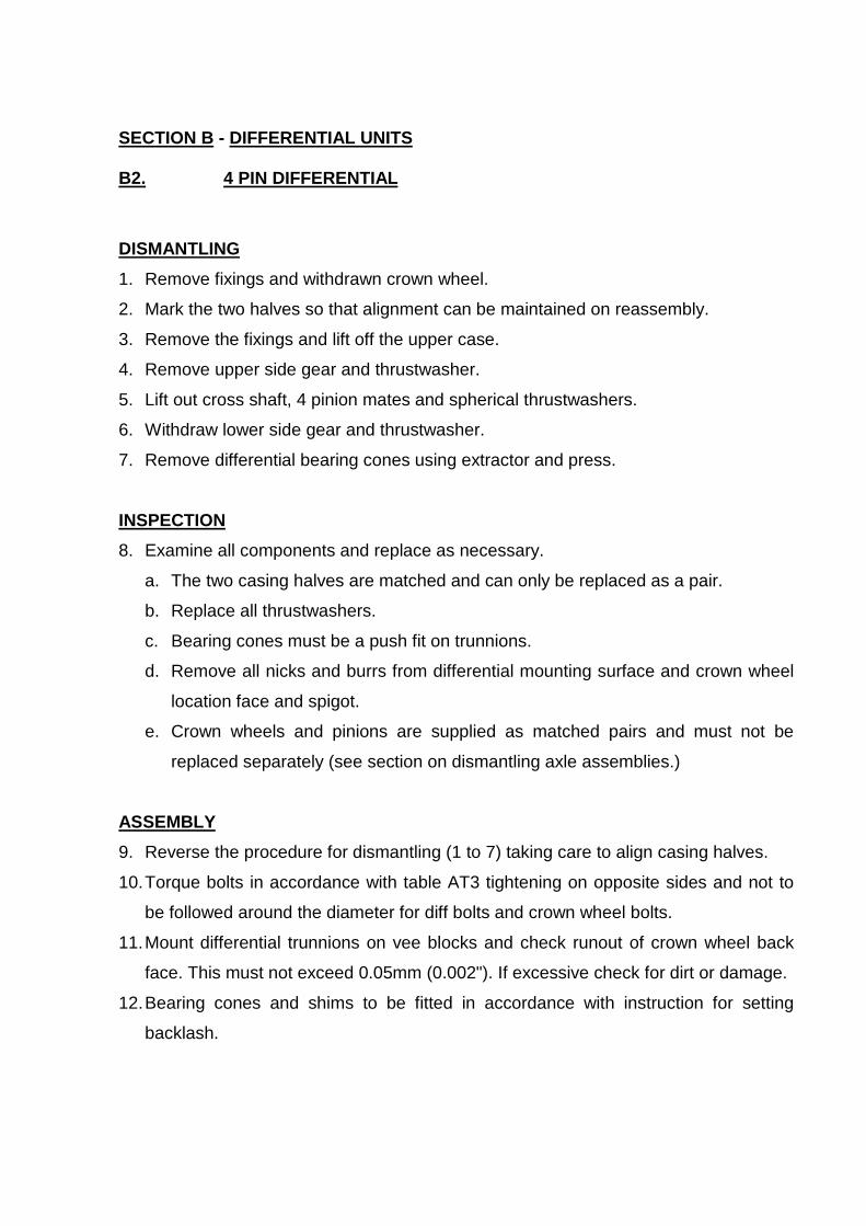
SECTION B - DIFFERENTIAL UNITS
B2. 4 PIN DIFFERENTIAL
DISMANTLING1. Remove fixings and withdrawn crown wheel.
2. Mark the two halves so that alignment can be maintained on reassembly.
3. Remove the fixings and lift off the upper case.
4. Remove upper side gear and thrustwasher.
5. Lift out cross shaft, 4 pinion mates and spherical thrustwashers.
6. Withdraw lower side gear and thrustwasher.
7. Remove differential bearing cones using extractor and press.
INSPECTION8. Examine all components and replace as necessary.
a. The two casing halves are matched and can only be replaced as a pair.
b. Replace all thrustwashers.
c. Bearing cones must be a push fit on trunnions.
d. Remove all nicks and burrs from differential mounting surface and crown wheel
location face and spigot.
e. Crown wheels and pinions are supplied as matched pairs and must not be
replaced separately (see section on dismantling axle assemblies.)
ASSEMBLY9. Reverse the procedure for dismantling (1 to 7) taking care to align casing halves.
10. Torque bolts in accordance with table AT3 tightening on opposite sides and not to
be followed around the diameter for diff bolts and crown wheel bolts.
11. Mount differential trunnions on vee blocks and check runout of crown wheel back
face. This must not exceed 0.05mm (0.002"). If excessive check for dirt or damage.
12. Bearing cones and shims to be fitted in accordance with instruction for setting
backlash.

Section C
HUB ASSEMBLIES

SECTION C - HUB ASSEMBLIES
C-1 - SEMI FLOATING HUB
1. Remove split pin.2. Unscrew shaft nut (rectifying damage is necessary).3. Pull-off hub using either conventional 3 leg puller or proprietary pullers engaging
either on extractor thread or hub studs.
N.B.
Shock treatment may be necessary in which case try:-
a. Striking opposite shaft end using soft hammer
Or
b. Striking hub to be removed with blunt cold chisel in proximity of shaft key.
4. Re-assemble in reverse order being sure to smear anti scuffing paste (rougeetc) on shaft taper.
Replace shaft key if any sign of fretting causing loose fit. Nut must be reallytight. Grease seal journal lightly with lithium-based grease.

SECTION C - HUB ASSEMBLIES
C-2 - SEMI FLOATING OUTRIGGER HUB
1. Remove split pin.2. Unscrew shaft nut (rectifying damage is necessary).3. Pull-off hub using either conventional 3 leg puller or proprietary pullers engaging
either on extractor thread or hub studs.
N.B.
Shock treatment may be necessary in which case try:-
c. Striking opposite shaft end using soft hammer
Or
d. Striking hub to be removed with blunt cold chisel in proximity of shaft key.
4. Re-assemble in reverse order being sure to smear anti scuffing paste (rougeetc) on shaft taper.
Replace shaft key if any sign of fretting causing loose fit. Nut must be reallytight. Grease seal journal lightly with lithium-based grease.

SECTION C - HUB ASSEMBLIES
C-3 - FULLY FLOATING HUB
1. Remove axle shaft securing bolts (discard tags if fitted).
2. Withdraw axle shafts (discard gasket if not torn in removal).
3. Unbend locking tab on Tube Nut Locktab and remove both tube nuts.
4. Steadying Hub to keep in position, withdraw outer Bearing Cone.
5. Pull off (with gentle shock if necessary) Hub.
6. Remove Inner Bearing Cone.
7. Examine Bearings Cups for signs of wear and replace both cup and cone ifnecessary. Cut-outs in the cup abutments are provided for drift access. Removalof inner bearing cup will cause oil seal to be knocked out at the same time. If anoil seal fault is suspected, seal must be removed in this manner.
8. Examine oil seal for wear, misplaced garter spring etc and re-new if necessary.Use smear of gasket sealant in either event. The oil seal journal on the axle tubeshould also be examined.
9. (If necessary) press-in replacement bearing cups, preferably with therecommended Service Tool or on a hand press using convenient dollies (whichwill not damage either bearing or bearing bore) to ensure proper abutment. Theinner bearing must be inserted complete with cone, liberally greased, which willthen be held in situ by the fitment of the oil seal.
10. Having greased oil seal journal, carefully offer Hub onto tube end with gentlepressure, until resistance is felt by bearing inner cone coming against its journal.Gently tab hub home with soft hammer until bearing is hard against itsabutment. (Note if gentle pressure does not result in movement of Hub,alignment is incorrect).
11. Position outer bearing cone, having applied a liberal quantity of lithium-basedgrease.
12. Tighten inner Tube Nut until slight binding is felt when rotating Hub in bothdirections. Back-off nut a quarter of a turn. Insert tab washer in place and tightenouter tube nut to a force of 100-120 lbf ft. Check end-float which should be asfollows:-

Drum Brake applications - .003'' - .008''Disc Brake applications - .003'' - .005''
If end float is incorrect, reposition inner tube nut as appropriate and repeatoperations.
13. Using large screwdriver, bend over locking tabs onto nearest convenient flat onboth inner and outer tube nuts.
14. Clean off faces of both hubs and shaft and fit new gasket, applying sealant toboth faces.
15. Replace axle shaft and secure bolts using either lockwashers or fresh lockstrapsas appropriate. Tighten bolts to 38 - 43 lbf.ft.

SECTION C - HUB ASSEMBLIES
C-4 SERVICE INSTRUCTIONS FOR ADJUSTMENT OF AXLE SHAFT END FLOATON SEMI FLOATING SEALED BRAKED AXLES (05HA SERIES)
The recommended end float for the axle shaft of the above axle is .003" - .008" (0.08 -0.20mm). As it is unlikely that servicing agents would have the necessary DTL gaugessuitable for directly measuring this adjustment, the following procedure isrecommended:
a. For replacing single axle shaft.
1. Jack axle clear of ground and remove road wheels.2. Remove hub assembly, bearing housing, hub adjustment shims and axle shaft
to be replaced.3. Re-assemble axle shaft taking care to carefully align splines in both differential
side gear and brake plates.4. Assemble bearing housing complete with bearing over axle shaft and locate on
brake housing studs.5. Fit bearing housing retaining nuts on the studs and finger tighten sufficient only
to locate bearing housing.6. Tap lightly end of shaft to ensure that no free play is apparent in opposing shaft
assembly. If necessary re-tighten bearing housing retainer nuts sufficient only to'lightly pinch' bearing housing.
7. Using feeler gauges measure gap between bearing housing and brake housingfaces. Measurements to be taken at four equally spaced points around thebearing housing circumference.
8. Obtain the mean reading and add to this dimension .005" (0.12mm).9. This dimension thus found is the shim thickness required.10. Remove bearing housing and re-assemble using above shim pack between
bearing housing and brake housing faces.11. Assemble and tighten bearing housing nuts to correct torque figure.12. Assemble hub componentry.13. Check that end float exists on axle shaft assembly.14. Re-fit road wheels.
b. For replacing both axle shafts.
When removing bearing housing note shim thickness as fitted. Re-assemble oneside of housing using a shim pack thickness the same as that removed. Re-assemble other side of axle using method as described in (a) above.

Section D
BRAKES

SECTION 3 - BRAKES
D - 1 - DRUM BRAKES
1. Remove the brake drums.
2. Remove the hub as outlined in section C1 or C2 as appropriate.
3. Remove brake securing screws which may be of either the nut and bolt varietyor tapped into the tube flange.
4. Note the position of the adjuster, actuator etc. to identify correct handling ofreplacement brake assembly.
5. Reassemble in reverse order as specified in the appropriate section. Ensure thatthe brake drum path is clear and smooth. Difficulty in fitting the brake drum maymean that the brake show adjuster is fully expanded.

SECTION 3 - BRAKES
D-2 - DISC BRAKES
1. Break the locking wire securing the two caliper mounting bolts.
2. Remove the caliper mounting bolts, being careful not to lose the washers andshims.
3. Remove the caliper assembly.
4. Clean the disc faces.
5. Present the replacement caliper assembly onto the mounting flange (havingensured the correct "handing").
6. Insert shims between the caliper lug and the mounting flange on the tube toensure that the (Hydraulic) pads are equidistant from the disc. The securingbolts must be tightened to ensure correct seating of all the components. Toapply these, first seat the small plain washer against the bolt head and then thelarge plain washer next to that.
7. Tighten to 35/40 lbt ft and reapply locking wire. If hand brakes are fitted, theseare self adjusting and will be positioned correctly after initial application of thehand brake lever.

SECTION D - BRAKES
D3 - INSTRUCTIONS FOR REPLACING AND ADJUSTING BRAKES FOR STL 5HAOIL IMMERSED BRAKED AXLES (S/F TYPE DESIGN).
DIS-ASSEMBLY
If brake adjustment only is required, the following axle strip down need not apply.
Adjustment instructions are given separately.
1. Remove axle shaft nut lock pin.2. Remove axle shaft lock nut and washer.3. Withdraw hub complete with Key.4. Remove the nuts and washers holding the bearing housing in position.5. Withdraw housing assembly from studs. The bearing housing assembly
incorporates the oil seal, shaft bearing cup and bearing housing 'O' ring.6. Carefully remove the retaining bearing housing shims taking care not to damage
them.7. Withdraw axle shaft complete with axle shaft bearing cone.8. Remove the nuts retaining brake housing plate.9. Withdraw brake housing cover plate from studs.10. Remove the brake friction discs and reaction plates which will now be loose
within the brake housing.11. Remove brake reaction pin.12. Remove brake housing pressed cover and gasket. Upon removal of this cover
the conical return spring will be free and should be removed also.13. From end opening of brake housing remove the circlip retaining the pin between
the pull rod and the brake actuator.14. Push pin through pull rod and swing pull rod away from actuator.15. Remove actuator from housing.16. Remove internal brake friction discs and reaction plates from brake housing.17. Discard all worn plates. Worn plates are identified when the plate surface goes
below both of the circular grooves. This worn condition is evidenced by thenoticeable increase in pedal effort for the same vehicle retardation.

ASSEMBLY
GENERAL NOTE
Replace all worn or damaged components and lightly grease bearings and oil sealsprior to assembly.
1. Insert correct number of internal brake friction discs and reaction plates intohousing in correct sequence.
2. Loosly assemble actuator plate into housing.3. Locate actuator plate arms in correct position with pull rod and insert locator pin
complete with inner circlip, from back of the brake housing.4. Attach outer circlip to pin. Use new circlip.5. Assemble correct number of brake friction discs and reaction plates onto shaft
spline in correct order.6. Assemble shaft complete with bearing cone together with brakes plates and
discs through actuator plate and inner friction discs and reaction plates, takingcare whilst engaging the shaft splines into both inner side gear and the brakediscs.
7. Assemble brake reaction pin into brake housing ensuring that all brake reactionplaces are correctly aligned.
8. Assemble brake cover plate over studs ensuring correct location of brakereaction pin. Fit cover plate locking nuts and tighten to correct torque. Use agood quality gasket sealant beneath plate surface, i.e. silicone gasketcompound.
9. Fit correct shim amount (i.e. that removed from the axle) over bearing housinglocation studs. Assemble bearing housing* together with bearing cup and sealonto studs. Fit lockwashers and nuts and tighten to recommended torque. Fitleather wiping seal.
10. Fit hub assembly* complete with bearing cup onto shaft.11. Fit shaft key.12. Fit shaft washer and nut and tighten to recommended torque.13. Fit new nut locking pin.
On axles built prior to June 1979, (Serial No. prefix F79) bearing housing05HA - 014-012 and hub 05HA-928-113 were used in place of the abovementioned components. (It should be noted that the old level hub andbearing housings are not interchangeable as individual items with the newlevel components).

ADJUSTMENT
1. Tighten pull rod nut to lock brakes and thus take up all slack in the system.2. Loosen pull rod nut until a clearance of .0001" (0.25mm) per working brake
surface is obtained. With an eight plate assembly this would give .016" (.4mm)*total clearance. This clearance should be measured by two shims of correctthickness being inserted between a suitable brake disc and brake reaction plateeither side of axle shaft from top cover.
* Although .016 (.4mm) is the theoretical clearance figure to use, in practice it isfound that a .015 shim is more readily available.
3. When correct adjustment is achieved re-assemble brake housing covercomplete with conical return spring correctly located in position.
RECOMMENDED TORQUE TIGHTNESS
Axle Shaft Nut - 130/140 lbf.ft (175/190 Nm)Bearing Housing Nuts - 38/43 lbf.ft (51/58Nm)Brake Cover Nuts - 65/75 lbf.ft (89/102 Nm)Brake Pressing Cover - 19/22 lbf.ft (26/30 Nm)Pressing Bolts

Section E
BLANK

Section F
AXLESHAFTS

SECTION F - AXLE SHAFTSF-1. SEMI FLOATING
1. Remove brake drum.
2. Remove hub in accordance with Page C1.
3. Remove the brake back plate retaining bolts, the outer oil seal assembly, thehub bearing retainer plate and the brake back plate, taking care not to lose ordamage any of the shaft bearing adjusting shims which control the shaftendfloat.
4. Check outer oil seal for wear, misplaced garter spring etc and replace isnecessary.
5. Remove the axle shaft with its taper roller bearing.
6. To remove a broken axle shaft, make a loop at one end of a length of stiff wire,slide the loop down the axle tube and over the broken end of the shaft for asufficient distance so that on pulling the loop will bind on the shaft and withdrawit from the differential side gear. This applies where sufficient shaft remains. (i.e.minimum length 6").
6a. To remove a broken axle shaft with the break close to the spline, it is necessarythen to withdraw the opposite shaft and remove the differential assemblycomplete i.e. follow the instruction conveyed in Pages A-1, A-2 or A-3.
7. Examine the shaft oil seal which is pressed inside the axle tube, and ifnecessary withdraw same and replace with a new seal.
8. Examine the shaft bearing for wear and if replacement is necessary, the conemay be withdrawn from the shaft by means of the extractor tool with suitableadaptor.
9. Fit the replacement bearing (if required) making sure that the cone is pressedsquarely on the bearing diameter until it firmly abuts against the shoulderprovided. If the bearing is not pressed home, it will creep in service, resulting inexcessive shaft endfloat, which will damage the surfaces due to hammering.
10. Re-assemble in reverse order ensuring inner shaft oil seal is not damaged whenshaft is re-fitted.
10a. If new bearing is fitted ensure correct axle shaft endfloat (.003" - .009") isobtained by the removal/addition of shims from one axle end only.
11. Refit hub in accordance with Page C-1.N.B. New paper gaskets must be fitted when components are re-assembled.
12. Re-grease the assembly by means of the grease nipple.

SECTION F - AXLE SHAFTSF-2. SEMI FLOATING OUTRIGGER
1. Remove brake drum.
2. Remove hub in accordance with Page C2.
3. Remove the bearing housing/brake back plate mounting bolts.
4. Remove the brake back plate and the bearing housing, taking care not to lose ordamage any of the hub bearing adjusting shims which control the shaft endfloat.
4a. Check oil seal as fitted into bearing housing for wear, misplaced garter spring etc and replace is necessary.
5. Remove axle shaft complete with bearing cone.
6. To remove a broken axle shaft, make a loop at one end of a length of stiff wire,slide the loop down the axle tube and over the broken end of the shaft for asufficient distance so that on pulling the loop will bind on the shaft and withdrawit from the differential side gear. This applies where sufficient shaft remains. (i.e.minimum length 6").
6a. To remove a broken axle shaft with the break close to the spline, it is necessarythen to withdraw the opposite shaft and remove the differential assemblycomplete i.e. follow the instruction conveyed in Page A-1, A-2 or A-3.
7. Examine shaft oil seal which is pressed inside the axle tube for wear, misplacedgarter spring etc and replace if necessary.
8. Examine the shaft bearing for where and replace if necessary.
9. If replacing axle shaft bearing ensure bearing cup is seated correctly in bearinghousing, if this is not done creeping will occur which will result in excessive shaftend float which in turn will damage the bearing.
10. Re-assemble components in reverse ensuring that inner shaft oil seal is notdamaged when shaft is re-fitted.
10a. If new bearing is fitted ensure correct axle shaft endfloat (.003" - .009") isobtained by the removal/addition of shims from one axle end only.
11. Refit hub in accordance with Page C-2.N.B. New paper gaskets must be fitted when components are re-assembled.
12. Re-grease the assembly by means of the grease nipple.

SECTION F - AXLE SHAFTS
F-3. FULLY FLOATING
This procedure is covered within the strip and re-build procedure for the fully floatinghub in Page C-3.

Section G
GEAR TOOTHCONTACT

T O O T H C O N T A C T C H A R T
Diagrams show contact on drive gear tooth.
TOOTH CONTACT CONDITION REMEDY
A IDEAL TOOTH CONTACTEvenly spread over profile,nearer toe than heel
0--0
B HIGH TOOTH CONTACTHeavy on the top of thedrive gear tooth profile.
Move the DrivePINION DEEPERinto MESHi.e. Reduce thepinion cone setting.
C LOW TOOTH CONTACTHeavy in the root of thedrive gear tooth profile.
Move the DrivePINION OUT ofMESH i.e. IncreaseThe pinion coneSetting.
D TOE CONTACTHard on the small end ofthe drive Gear tooth.
Move the DriveGEAR OUT of meshi.e. INCREASEBACKLASH
E HEEL CONTACTHard on the large end ofthe drive gear tooth.
Move the Drive GEARinto MESH i.e.DECREASEBACKLASH BUTMAINTAIN MINIMUMBACKLASH

Section H
TABLES

S A L I S B U R Y T R A N S M I S S I O N L I M I T E D
TABLE AT1
4HA/4HU 5HA 7HA/7DR 8HA/8DR 10HA/10HD/10DR
NOMINALPINIONCONE
2.625 2.9685 2.219 3.125 3.500
DIFFBEARINGSEAT
DIAMETER
3.2660
3.2674
3.4385
3.4399
2.8920
3.8934
3.8140
3.8155
4.1273 } } } Heavy }
4.1256 }
3.8155 } } } Light }
3.8140 }

S A L I S B U R Y T R A N S M I S S I O N L I M I T E D
TABLE AT2
MODEL TORQUE TOTURN PINIONWITH OIL
A LBF. IN.
TORQUE TOTURN PINION ANDDIFFERENTIAL
* B LBF. IN.`
TORQUE TO TURNCOMPLETE AXLE
* C LBF. IN.
4HU 2 PIN 30-40 5-15 2-10
4HU POWER-LOK 30-40 10-20 2-10
4HA/4HS 30-40 5-15 2-10
5HA 23-35 5-15
10HD 30-40 5-15
7DR/8DR8HA/8HS/10HA
**30-40
5-105-15
NOTE:
Torque B is additional to A and C is additional to B.
i.e. 35 at A + 10 at B = 45 + 8 at C = 53lbf in total.
7DR/8DR/10DR Helical Ratio Torque to turn helicalGears and Hypoid Pinion
lbf. In.
1.4 - 2.0 6 - 92.0 - 2.6 4 - 72.6 - 4.4 3 - 5
Torque to turn hypoid pinion assy 15 - 20 lbf. In.
Primary input pinion bearing end float 0.002" - 0.005"

S A L I S B U R Y T R A N S M I S S I O N L I M I T E D
TABLE AT3
TORQUE TIGHTNESS lbf ft
MODEL DRIVEPINIONNUT*
DRIVEGEARBOLT
DIFF BRG.CAPBOLT
GEARCARRIERCOVERSCREW
DIFFCASEBOLT
4HA/4HU ¾" UNF 'T' 3/8" or 7/16"UNF 'X'
½" UNC 'R' 5/16" UNC 'S' 3/8" UNC 'X'
4HS 180/190 49/56-70/88 63/72 18/20 43/50
5HA 180/190 7/16" UNF 'X' 63/72 3/8" UNC 'S' 5/16" UNC 'W'
70/88 29/33 23/26
7HA 5/8" UNF 3/8" UNF 'X' 3/8" UNC 'T' 5/16" UNC 'S' 3/8" UNC 'X'
95/105 49/56 32/36 18/20 43/50
8HA/10HA 7/8" UNF ½" UNF 'X' ½" UNC 'R' 3/8" UNC 'S' 7/16" UNC 'V'
250/270 118/135 63/72 20/28 60/69
8HD 250/270 118/135 63/72 3/8" UNC 'R' 60/69
26/30
TORQUE TIGHTNESS Nm
MODEL DRIVEPINIONNUT*
DRIVEGEARBOLT
DIFF BRG.CAPBOLT
GEARCARRIERCOVERSCREW
DIFF.CASEBOLT
STRADDLEHSG.BO
8HA/10HA 24mm- 8* 12mm -12.9 Grade129/142
12mm -10.9 Grade125/142
10mm -8.8 Grade27/38
12mm -8.8 Grade98/102
• For axles with collapsible spacers the nut is tightened until the torque to turn thepinion is in accordance with table AT2.
S A
L I S
B U
R Y
T
R A
N S
M I
S S
I O N
L
I M I
T E
D
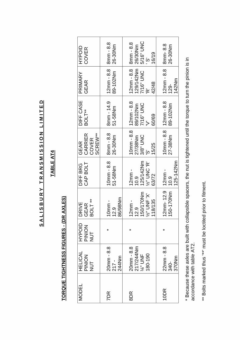
TAB
LE A
T4
TOR
QU
E TI
GH
TNES
S FI
GU
RES
- (D
R A
XLES
)
MO
DEL
HEL
ICAL
PIN
ION
NU
T
HYP
OID
PIN
ION
NU
T
DR
IVE
GEA
RBO
LT **
DIF
F BR
GC
AP B
OLT
GEA
RC
ARR
IER
CO
VER
SCR
EW**
DIF
F C
ASE
BOLT
**PR
IMAR
YG
EAR
HYP
OID
CO
VER
7DR
20m
m -
8.8
217
-24
4Nm
*10
mm
-12
.986
/98N
m
10m
m -
8.8
51-5
8Nm
8mm
- 8.
826
-30N
m8m
m -
14.9
51-5
8Nm
12m
m -
8.8
89-1
02N
m8m
m -
8.8
26-3
0Nm
8DR
20m
m -
8.8
217/
244N
m¼
" UN
F18
0-19
0
*12
mm
-12
.915
0/17
0Nm
½" U
NF
'X'
118/
135
12m
m -
10.9
125/
142N
m½
" UN
C 'R
'63
/72
10m
m -
8.8
27/3
8Nm
3/8"
UN
C'S
'15
/25
12m
m -
8.8
89/1
02N
m7/
16" U
NC
'V'
60/6
9
12m
m -
8.8
129/
142N
m7/
16" U
NC
'R'
42/4
8
8mm
- 8.
826
/30N
m5/
16" U
NC
' S'
16/1
9
10D
R22
mm
- 8.
834
0-37
0Nm
*12
mm
- 12.
915
0-17
0Nm
12m
m -
10.9
125-
142N
m
10m
m -
8.8
27-3
8Nm
12m
m -
8.8
89-1
02N
m12
mm
- 8.
812
9-14
2Nm
8mm
- 8.8
26-3
0Nm
* Bec
ause
thes
e ax
les
are
built
with
col
laps
ible
spa
cers
, the
nut
is ti
ghte
ned
until
the
torq
ue to
turn
the
pini
on is
inac
cord
ance
with
tabl
e AT
2.
** B
olts
mar
ked
thus
'**'
mus
t be
loct
ited
prio
r to
fitm
ent.

Section J
DIAGRAMS

SECTION J: DIAGRAMS
J1

SECTION J: DIAGRAMS
J2