Embed Size (px)
Citation preview

SERVICE MANUAL
Screw Compressor
Model: CSDNo.: 9.5700.02E
Manufacturer:
KAESER KOMPRESSOREN GmbH
96410 Coburg � PO Box 2143 � GERMANY � Tel. + 49---(0)9561---6400 � Fax + 49---(0)9561---640130
http://www.kaeser.com


ContentsChapter --- page
i
1 Regarding this Document 1 --- 1. . . . . . . . . . . . . . . . . . . . . . . . . . . . . . . . . . . . .
1.1 Handling the Document 1 --- 1. . . . . . . . . . . . . . . . . . . . . . . . . . . . . . . . . . . . . . . . . . . . .1.2 Further Documents 1 --- 1. . . . . . . . . . . . . . . . . . . . . . . . . . . . . . . . . . . . . . . . . . . . . . . . .
1.3 Copyright 1 --- 1. . . . . . . . . . . . . . . . . . . . . . . . . . . . . . . . . . . . . . . . . . . . . . . . . . . . . . . . .1.4 Symbols and Identifications 1 --- 1. . . . . . . . . . . . . . . . . . . . . . . . . . . . . . . . . . . . . . . . . .1.4.1 Warning notices 1 --- 1. . . . . . . . . . . . . . . . . . . . . . . . . . . . . . . . . . . . . . . . . . . . . . . . . . . .
1.4.2 Miscellaneous notices and symbols 1 --- 2. . . . . . . . . . . . . . . . . . . . . . . . . . . . . . . . . . .
2 Technical Specification 2 --- 3. . . . . . . . . . . . . . . . . . . . . . . . . . . . . . . . . . . . . . .
2.1 Weight 2 --- 3. . . . . . . . . . . . . . . . . . . . . . . . . . . . . . . . . . . . . . . . . . . . . . . . . . . . . . . . . . . .2.2 Temperature 2 --- 3. . . . . . . . . . . . . . . . . . . . . . . . . . . . . . . . . . . . . . . . . . . . . . . . . . . . . . .2.3 Ambient Conditions 2 --- 4. . . . . . . . . . . . . . . . . . . . . . . . . . . . . . . . . . . . . . . . . . . . . . . . .
2.4 Pressure 2 --- 4. . . . . . . . . . . . . . . . . . . . . . . . . . . . . . . . . . . . . . . . . . . . . . . . . . . . . . . . . .2.5 Sound Pressure Level 2 --- 4. . . . . . . . . . . . . . . . . . . . . . . . . . . . . . . . . . . . . . . . . . . . . . .2.6 Motor and Performance 2 --- 4. . . . . . . . . . . . . . . . . . . . . . . . . . . . . . . . . . . . . . . . . . . . .
2.6.1 Compressor motor: 2 --- 4. . . . . . . . . . . . . . . . . . . . . . . . . . . . . . . . . . . . . . . . . . . . . . . . .2.6.2 Fan Motor 2 --- 5. . . . . . . . . . . . . . . . . . . . . . . . . . . . . . . . . . . . . . . . . . . . . . . . . . . . . . . . .2.7 Cooling oil 2 --- 5. . . . . . . . . . . . . . . . . . . . . . . . . . . . . . . . . . . . . . . . . . . . . . . . . . . . . . . .
2.7.1 Recommended cooling oil 2 --- 5. . . . . . . . . . . . . . . . . . . . . . . . . . . . . . . . . . . . . . . . . . .2.7.2 Cooling Oil Volumes 2 --- 6. . . . . . . . . . . . . . . . . . . . . . . . . . . . . . . . . . . . . . . . . . . . . . . .
2.8 Power supply 2 --- 6. . . . . . . . . . . . . . . . . . . . . . . . . . . . . . . . . . . . . . . . . . . . . . . . . . . . . .2.8.1 Power supply 2 --- 6. . . . . . . . . . . . . . . . . . . . . . . . . . . . . . . . . . . . . . . . . . . . . . . . . . . . . .2.8.2 Power supply specifications 2 --- 6. . . . . . . . . . . . . . . . . . . . . . . . . . . . . . . . . . . . . . . . . .
2.9 Water cooling (option K2) 2 --- 8. . . . . . . . . . . . . . . . . . . . . . . . . . . . . . . . . . . . . . . . . . .2.9.1 Design data 2 --- 8. . . . . . . . . . . . . . . . . . . . . . . . . . . . . . . . . . . . . . . . . . . . . . . . . . . . . . .2.9.2 Cooling Water Quality 2 --- 8. . . . . . . . . . . . . . . . . . . . . . . . . . . . . . . . . . . . . . . . . . . . . . .
2.10 Internal Heat Recovery (option W2 / W3) 2 --- 9. . . . . . . . . . . . . . . . . . . . . . . . . . . . . . .
3 Safety and Responsibility 3 --- 11. . . . . . . . . . . . . . . . . . . . . . . . . . . . . . . . . . . . .
3.1 Correct Use 3 --- 11. . . . . . . . . . . . . . . . . . . . . . . . . . . . . . . . . . . . . . . . . . . . . . . . . . . . . . .3.2 Incorrect Use 3 --- 11. . . . . . . . . . . . . . . . . . . . . . . . . . . . . . . . . . . . . . . . . . . . . . . . . . . . . .3.3 User’s Responsibilities 3 --- 11. . . . . . . . . . . . . . . . . . . . . . . . . . . . . . . . . . . . . . . . . . . . . .
3.4 Safety Devices 3 --- 12. . . . . . . . . . . . . . . . . . . . . . . . . . . . . . . . . . . . . . . . . . . . . . . . . . . . .3.5 Hazards 3 --- 12. . . . . . . . . . . . . . . . . . . . . . . . . . . . . . . . . . . . . . . . . . . . . . . . . . . . . . . . . .3.5.1 Danger from electric current 3 --- 12. . . . . . . . . . . . . . . . . . . . . . . . . . . . . . . . . . . . . . . . .
3.5.2 Danger from released spring force 3 --- 13. . . . . . . . . . . . . . . . . . . . . . . . . . . . . . . . . . . .3.5.3 Danger from released compressed air 3 --- 13. . . . . . . . . . . . . . . . . . . . . . . . . . . . . . . . .3.5.4 Further dangers 3 --- 13. . . . . . . . . . . . . . . . . . . . . . . . . . . . . . . . . . . . . . . . . . . . . . . . . . . .
3.6 Warning Symbols 3 --- 14. . . . . . . . . . . . . . . . . . . . . . . . . . . . . . . . . . . . . . . . . . . . . . . . . .3.7 Emergencies 3 --- 14. . . . . . . . . . . . . . . . . . . . . . . . . . . . . . . . . . . . . . . . . . . . . . . . . . . . . .
3.7.1 Fire fighting 3 --- 14. . . . . . . . . . . . . . . . . . . . . . . . . . . . . . . . . . . . . . . . . . . . . . . . . . . . . . .3.7.2 Cooling oil 3 --- 14. . . . . . . . . . . . . . . . . . . . . . . . . . . . . . . . . . . . . . . . . . . . . . . . . . . . . . . .3.8 Environmental Protection 3 --- 14. . . . . . . . . . . . . . . . . . . . . . . . . . . . . . . . . . . . . . . . . . . .

ContentsChapter --- page
ii
4 Design and Function 4 --- 15. . . . . . . . . . . . . . . . . . . . . . . . . . . . . . . . . . . . . . . . . .
4.1 Machine Overview 4 --- 15. . . . . . . . . . . . . . . . . . . . . . . . . . . . . . . . . . . . . . . . . . . . . . . . . .
4.1.1 Cabinet 4 --- 15. . . . . . . . . . . . . . . . . . . . . . . . . . . . . . . . . . . . . . . . . . . . . . . . . . . . . . . . . . .
4.1.2 Function 4 --- 15. . . . . . . . . . . . . . . . . . . . . . . . . . . . . . . . . . . . . . . . . . . . . . . . . . . . . . . . . .
4.2 Options 4 --- 17. . . . . . . . . . . . . . . . . . . . . . . . . . . . . . . . . . . . . . . . . . . . . . . . . . . . . . . . . . .
4.2.1 Machine mountings (option H1) 4 --- 17. . . . . . . . . . . . . . . . . . . . . . . . . . . . . . . . . . . . . .
4.2.2 Cooling air filter mats (option K3) 4 --- 17. . . . . . . . . . . . . . . . . . . . . . . . . . . . . . . . . . . . .
4.2.3 Water cooling (option K2) 4 --- 17. . . . . . . . . . . . . . . . . . . . . . . . . . . . . . . . . . . . . . . . . . .
4.2.4 Heat recovery 4 --- 17. . . . . . . . . . . . . . . . . . . . . . . . . . . . . . . . . . . . . . . . . . . . . . . . . . . . .
4.3 Operating States and Control Modes 4 --- 18. . . . . . . . . . . . . . . . . . . . . . . . . . . . . . . . . .
4.3.1 Operating states 4 --- 18. . . . . . . . . . . . . . . . . . . . . . . . . . . . . . . . . . . . . . . . . . . . . . . . . . .
4.3.2 Tasks of the controller 4 --- 18. . . . . . . . . . . . . . . . . . . . . . . . . . . . . . . . . . . . . . . . . . . . . . .
4.3.3 Control Modes 4 --- 18. . . . . . . . . . . . . . . . . . . . . . . . . . . . . . . . . . . . . . . . . . . . . . . . . . . . .
4.3.4 Modulating control (option C1) 4 --- 19. . . . . . . . . . . . . . . . . . . . . . . . . . . . . . . . . . . . . . .
4.4 Safety Devices 4 --- 19. . . . . . . . . . . . . . . . . . . . . . . . . . . . . . . . . . . . . . . . . . . . . . . . . . . . .
4.5 SIGMA CONTROL Keys and Indicators 4 --- 20. . . . . . . . . . . . . . . . . . . . . . . . . . . . . . . .
5 Installation and Operating Conditions 5 --- 22. . . . . . . . . . . . . . . . . . . . . . . . . .
5.1 Ambient Conditions 5 --- 22. . . . . . . . . . . . . . . . . . . . . . . . . . . . . . . . . . . . . . . . . . . . . . . . .
5.2 Installation Conditions 5 --- 22. . . . . . . . . . . . . . . . . . . . . . . . . . . . . . . . . . . . . . . . . . . . . .
5.2.1 Place of installation and space required 5 --- 22. . . . . . . . . . . . . . . . . . . . . . . . . . . . . . . .
5.2.2 Ventilation 5 --- 23. . . . . . . . . . . . . . . . . . . . . . . . . . . . . . . . . . . . . . . . . . . . . . . . . . . . . . . . .
5.2.3 Operating in a compressed air network 5 --- 24. . . . . . . . . . . . . . . . . . . . . . . . . . . . . . . .
6 Installation 6 --- 25. . . . . . . . . . . . . . . . . . . . . . . . . . . . . . . . . . . . . . . . . . . . . . . . . .
6.1 Safety 6 --- 25. . . . . . . . . . . . . . . . . . . . . . . . . . . . . . . . . . . . . . . . . . . . . . . . . . . . . . . . . . . .
6.2 Report any Transport Damage 6 --- 25. . . . . . . . . . . . . . . . . . . . . . . . . . . . . . . . . . . . . . . .
6.3 Install the Compressed Air Connection 6 --- 25. . . . . . . . . . . . . . . . . . . . . . . . . . . . . . . .
6.4 Electrical Connection 6 --- 26. . . . . . . . . . . . . . . . . . . . . . . . . . . . . . . . . . . . . . . . . . . . . . .
6.5 Options 6 --- 26. . . . . . . . . . . . . . . . . . . . . . . . . . . . . . . . . . . . . . . . . . . . . . . . . . . . . . . . . . .
6.5.1 Machine fixing (option H1) 6 --- 26. . . . . . . . . . . . . . . . . . . . . . . . . . . . . . . . . . . . . . . . . . .
6.5.2 Water cooling connection (option K2) 6 --- 26. . . . . . . . . . . . . . . . . . . . . . . . . . . . . . . . .
6.5.3 Heat recovery system connection 6 --- 27. . . . . . . . . . . . . . . . . . . . . . . . . . . . . . . . . . . . .
7 Initial Start---up 7 --- 29. . . . . . . . . . . . . . . . . . . . . . . . . . . . . . . . . . . . . . . . . . . . . . .
7.1 Before Initial Start ---up (or Recommissioning) 7 --- 29. . . . . . . . . . . . . . . . . . . . . . . . . . .
7.2 Check Installation and Operating Conditions 7 --- 29. . . . . . . . . . . . . . . . . . . . . . . . . . .
7.3 Setting the overload protection cut ---out 7 --- 29. . . . . . . . . . . . . . . . . . . . . . . . . . . . . . .
7.4 Motor Protection Switch Setting 7 --- 30. . . . . . . . . . . . . . . . . . . . . . . . . . . . . . . . . . . . . .
7.5 Pour Cooling Oil into the Inlet Port 7 --- 30. . . . . . . . . . . . . . . . . . . . . . . . . . . . . . . . . . . .
7.6 Checking Direction of Rotation 7 --- 31. . . . . . . . . . . . . . . . . . . . . . . . . . . . . . . . . . . . . . .
7.7 Initial Start ---up 7 --- 31. . . . . . . . . . . . . . . . . . . . . . . . . . . . . . . . . . . . . . . . . . . . . . . . . . . . .
7.8 Setting Network Pressure 7 --- 31. . . . . . . . . . . . . . . . . . . . . . . . . . . . . . . . . . . . . . . . . . . .

ContentsChapter --- page
iii
8 Operation 8 --- 32. . . . . . . . . . . . . . . . . . . . . . . . . . . . . . . . . . . . . . . . . . . . . . . . . . .
8.1 Switching On and Off 8 --- 32. . . . . . . . . . . . . . . . . . . . . . . . . . . . . . . . . . . . . . . . . . . . . . .8.1.1 Switching on 8 --- 32. . . . . . . . . . . . . . . . . . . . . . . . . . . . . . . . . . . . . . . . . . . . . . . . . . . . . .
8.1.2 Automatic restart 8 --- 32. . . . . . . . . . . . . . . . . . . . . . . . . . . . . . . . . . . . . . . . . . . . . . . . . . .8.1.3 Switching off 8 --- 33. . . . . . . . . . . . . . . . . . . . . . . . . . . . . . . . . . . . . . . . . . . . . . . . . . . . . .8.2 Switching Off in an Emergency and Switching On Again 8 --- 33. . . . . . . . . . . . . . . . .
8.3 Remote On and Off Switching 8 --- 33. . . . . . . . . . . . . . . . . . . . . . . . . . . . . . . . . . . . . . . .8.4 Switching on and off with the Clock 8 --- 34. . . . . . . . . . . . . . . . . . . . . . . . . . . . . . . . . . .8.5 Acknowledging and Resetting Warning and Alarm Messages 8 --- 34. . . . . . . . . . . . .
8.5.1 Resetting alarm messages 8 --- 34. . . . . . . . . . . . . . . . . . . . . . . . . . . . . . . . . . . . . . . . . . .8.5.2 Resetting warning messages 8 --- 35. . . . . . . . . . . . . . . . . . . . . . . . . . . . . . . . . . . . . . . . .
9 Event Recognition and Fault Rectification 9 --- 36. . . . . . . . . . . . . . . . . . . . . .
9.1 Alarms (machine shut ---down, red LED blinking) 9 --- 36. . . . . . . . . . . . . . . . . . . . . . . .9.2 Warning Messages (yellow LED blinking) 9 --- 41. . . . . . . . . . . . . . . . . . . . . . . . . . . . . .
9.3 Miscellaneous events (faults) 9 --- 44. . . . . . . . . . . . . . . . . . . . . . . . . . . . . . . . . . . . . . . . .
10 Maintenance 10 --- 46. . . . . . . . . . . . . . . . . . . . . . . . . . . . . . . . . . . . . . . . . . . . . . . . .
10.1 Safety 10 --- 46. . . . . . . . . . . . . . . . . . . . . . . . . . . . . . . . . . . . . . . . . . . . . . . . . . . . . . . . . . . .
10.2 Maintenance Schedule 10 --- 47. . . . . . . . . . . . . . . . . . . . . . . . . . . . . . . . . . . . . . . . . . . . . .10.2.1 Resetting maintenance interval counters 10 --- 47. . . . . . . . . . . . . . . . . . . . . . . . . . . . . . .
10.2.2 Regular maintenance work 10 --- 48. . . . . . . . . . . . . . . . . . . . . . . . . . . . . . . . . . . . . . . . . .10.2.3 Oil change intervals 10 --- 48. . . . . . . . . . . . . . . . . . . . . . . . . . . . . . . . . . . . . . . . . . . . . . . . .10.2.4 Regular service work 10 --- 49. . . . . . . . . . . . . . . . . . . . . . . . . . . . . . . . . . . . . . . . . . . . . . . .
10.3 Cooler Maintenance 10 --- 50. . . . . . . . . . . . . . . . . . . . . . . . . . . . . . . . . . . . . . . . . . . . . . . .10.3.1 Air cooling (option K1) 10 --- 50. . . . . . . . . . . . . . . . . . . . . . . . . . . . . . . . . . . . . . . . . . . . . .10.3.2 Filter mat maintenance (option K3) 10 --- 50. . . . . . . . . . . . . . . . . . . . . . . . . . . . . . . . . . . .
10.3.3 Water cooling maintenance (option K2) 10 --- 51. . . . . . . . . . . . . . . . . . . . . . . . . . . . . . . .10.4 Internal Heat Recovery Maintenance (option W2 / W3) 10 --- 52. . . . . . . . . . . . . . . . . . .
10.5 Air Filter Maintenance. 10 --- 52. . . . . . . . . . . . . . . . . . . . . . . . . . . . . . . . . . . . . . . . . . . . . .10.6 Filter mat maintenance (control cabinet ventilator) 10 --- 53. . . . . . . . . . . . . . . . . . . . . . .10.7 Electric motor maintenance 10 --- 54. . . . . . . . . . . . . . . . . . . . . . . . . . . . . . . . . . . . . . . . . .
10.8 Checking the Coupling 10 --- 55. . . . . . . . . . . . . . . . . . . . . . . . . . . . . . . . . . . . . . . . . . . . . .10.9 Venting the Machine Manually 10 --- 56. . . . . . . . . . . . . . . . . . . . . . . . . . . . . . . . . . . . . . . .10.10 Checking and Topping up the Cooling Oil 10 --- 57. . . . . . . . . . . . . . . . . . . . . . . . . . . . . .
10.10.1 Check cooling oil level. 10 --- 57. . . . . . . . . . . . . . . . . . . . . . . . . . . . . . . . . . . . . . . . . . . . . .10.10.2 Topping up the cooling oil 10 --- 58. . . . . . . . . . . . . . . . . . . . . . . . . . . . . . . . . . . . . . . . . . .10.11 Changing the Cooling Oil 10 --- 60. . . . . . . . . . . . . . . . . . . . . . . . . . . . . . . . . . . . . . . . . . . .
10.12 Oil filter maintenance 10 --- 63. . . . . . . . . . . . . . . . . . . . . . . . . . . . . . . . . . . . . . . . . . . . . . .10.13 Checking the Pressure Relief Valve. 10 --- 64. . . . . . . . . . . . . . . . . . . . . . . . . . . . . . . . . . .
10.14 Changing the Oil Separator Cartridge 10 --- 65. . . . . . . . . . . . . . . . . . . . . . . . . . . . . . . . .10.15 Logging Maintenance Work 10 --- 67. . . . . . . . . . . . . . . . . . . . . . . . . . . . . . . . . . . . . . . . . .

ContentsChapter --- page
iv
11 Spares, Operating Materials, Service 11 --- 68. . . . . . . . . . . . . . . . . . . . . . . . . . .
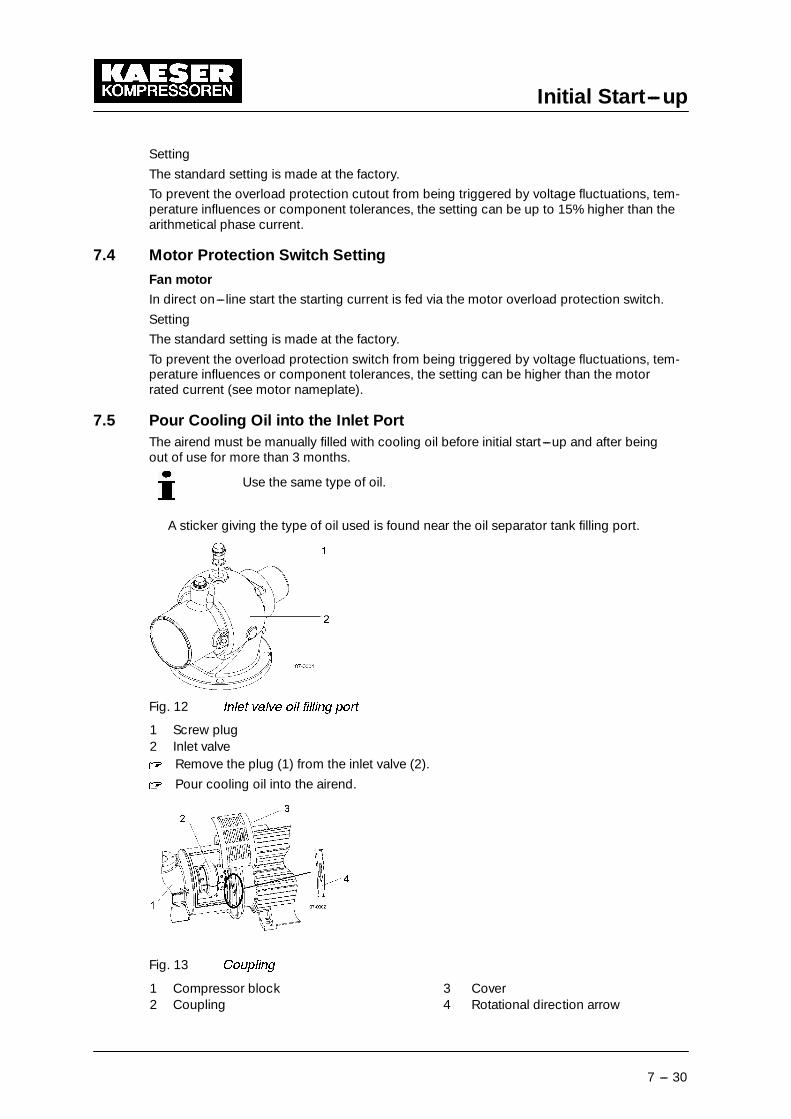
11.1 Note the nameplate 11 --- 68. . . . . . . . . . . . . . . . . . . . . . . . . . . . . . . . . . . . . . . . . . . . . . . . .11.2 Ordering Maintenance Parts and Operating Materials 11 --- 68. . . . . . . . . . . . . . . . . . . .
11.3 Maintenance Contract 11 --- 68. . . . . . . . . . . . . . . . . . . . . . . . . . . . . . . . . . . . . . . . . . . . . .11.4 Service Addresses 11 --- 68. . . . . . . . . . . . . . . . . . . . . . . . . . . . . . . . . . . . . . . . . . . . . . . . . .11.5 Spare Parts for Service and Repair 11 --- 68. . . . . . . . . . . . . . . . . . . . . . . . . . . . . . . . . . . .
12 De---commissioning, Storage and Transport 12 --- 75. . . . . . . . . . . . . . . . . . . .
12.1 De---commissioning 12 --- 75. . . . . . . . . . . . . . . . . . . . . . . . . . . . . . . . . . . . . . . . . . . . . . . .
12.2 Packing 12 --- 75. . . . . . . . . . . . . . . . . . . . . . . . . . . . . . . . . . . . . . . . . . . . . . . . . . . . . . . . . . .12.3 Storage 12 --- 75. . . . . . . . . . . . . . . . . . . . . . . . . . . . . . . . . . . . . . . . . . . . . . . . . . . . . . . . . . .12.4 Transporting 12 --- 76. . . . . . . . . . . . . . . . . . . . . . . . . . . . . . . . . . . . . . . . . . . . . . . . . . . . . . .
12.5 Disposal 12 --- 76. . . . . . . . . . . . . . . . . . . . . . . . . . . . . . . . . . . . . . . . . . . . . . . . . . . . . . . . . .
13 Annex 13 --- 77. . . . . . . . . . . . . . . . . . . . . . . . . . . . . . . . . . . . . . . . . . . . . . . . . . . . . . .
13.1 Conformity 13 --- 77. . . . . . . . . . . . . . . . . . . . . . . . . . . . . . . . . . . . . . . . . . . . . . . . . . . . . . . .
13.2 Diagrams and Drawings 13 --- 77. . . . . . . . . . . . . . . . . . . . . . . . . . . . . . . . . . . . . . . . . . . . .13.2.1 Pipeline and instrument flow diagram (P&I diagrams) 13 --- 77. . . . . . . . . . . . . . . . . . . .13.2.2 Pipeline and instrument flow diagram (option C1) 13 --- 83. . . . . . . . . . . . . . . . . . . . . . .
13.2.3 Dimensional drawing 13 --- 89. . . . . . . . . . . . . . . . . . . . . . . . . . . . . . . . . . . . . . . . . . . . . . .13.2.4 Electrical diagram 13 --- 95. . . . . . . . . . . . . . . . . . . . . . . . . . . . . . . . . . . . . . . . . . . . . . . . . .

Directory of IllustrationsChapter --- page
v
Fig. 1 Cabinet 4 --- 15. . . . . . . . . . . . . . . . . . . . . . . . . . . . . . . . . . . . . . . . . . . . . . . . . . . . . . . . . . . .
Fig. 2 Air ---cooled machine 4 --- 16. . . . . . . . . . . . . . . . . . . . . . . . . . . . . . . . . . . . . . . . . . . . . . . . .Fig. 3 Cooling air filter mats 4 --- 17. . . . . . . . . . . . . . . . . . . . . . . . . . . . . . . . . . . . . . . . . . . . . . . .Fig. 4 Water cooling 4 --- 17. . . . . . . . . . . . . . . . . . . . . . . . . . . . . . . . . . . . . . . . . . . . . . . . . . . . . . .
Fig. 5 Internal heat recovery 4 --- 18. . . . . . . . . . . . . . . . . . . . . . . . . . . . . . . . . . . . . . . . . . . . . . . .Fig. 6 SIGMA CONTROL keys 4 --- 20. . . . . . . . . . . . . . . . . . . . . . . . . . . . . . . . . . . . . . . . . . . . . .
Fig. 7 SIGMA CONTROL indicators 4 --- 21. . . . . . . . . . . . . . . . . . . . . . . . . . . . . . . . . . . . . . . . . .Fig. 8 Installation recommendation, dimensions [mm] 5 --- 23. . . . . . . . . . . . . . . . . . . . . . . . . .Fig. 9 Compressed Air Connection 6 --- 25. . . . . . . . . . . . . . . . . . . . . . . . . . . . . . . . . . . . . . . . . .
Fig. 10 Water cooling connection 6 --- 27. . . . . . . . . . . . . . . . . . . . . . . . . . . . . . . . . . . . . . . . . . . . .Fig. 11 Heat recovery 6 --- 28. . . . . . . . . . . . . . . . . . . . . . . . . . . . . . . . . . . . . . . . . . . . . . . . . . . . . . .Fig. 12 Inlet valve oil filling port 7 --- 30. . . . . . . . . . . . . . . . . . . . . . . . . . . . . . . . . . . . . . . . . . . . . . .
Fig. 13 Coupling 7 --- 30. . . . . . . . . . . . . . . . . . . . . . . . . . . . . . . . . . . . . . . . . . . . . . . . . . . . . . . . . . .Fig. 14 Switching On and Off 8 --- 32. . . . . . . . . . . . . . . . . . . . . . . . . . . . . . . . . . . . . . . . . . . . . . . .Fig. 15 Switching off in an emergency 8 --- 33. . . . . . . . . . . . . . . . . . . . . . . . . . . . . . . . . . . . . . . . .
Fig. 16 Acknowledging and Resetting Warning and Alarm Messages 8 --- 34. . . . . . . . . . . . . . .Fig. 17 Cleaning the cooler 10 --- 50. . . . . . . . . . . . . . . . . . . . . . . . . . . . . . . . . . . . . . . . . . . . . . . . . .
Fig. 18 Cooler filter mats 10 --- 51. . . . . . . . . . . . . . . . . . . . . . . . . . . . . . . . . . . . . . . . . . . . . . . . . . . .Fig. 19 Air filter maintenance. 10 --- 52. . . . . . . . . . . . . . . . . . . . . . . . . . . . . . . . . . . . . . . . . . . . . . . .Fig. 20 Control cabinet ventilator 10 --- 53. . . . . . . . . . . . . . . . . . . . . . . . . . . . . . . . . . . . . . . . . . . . .
Fig. 21 Compressor motor maintenance 10 --- 54. . . . . . . . . . . . . . . . . . . . . . . . . . . . . . . . . . . . . . .Fig. 22 Checking the Coupling 10 --- 55. . . . . . . . . . . . . . . . . . . . . . . . . . . . . . . . . . . . . . . . . . . . . . .Fig. 23 Ventilate the machine. 10 --- 57. . . . . . . . . . . . . . . . . . . . . . . . . . . . . . . . . . . . . . . . . . . . . . . .
Fig. 24 Check cooling oil level. 10 --- 58. . . . . . . . . . . . . . . . . . . . . . . . . . . . . . . . . . . . . . . . . . . . . . .Fig. 25 Topping up the cooling oil 10 --- 59. . . . . . . . . . . . . . . . . . . . . . . . . . . . . . . . . . . . . . . . . . . .
Fig. 26 Changing the Cooling Oil, Oil Separator Tank 10 --- 60. . . . . . . . . . . . . . . . . . . . . . . . . . . .Fig. 27 Changing the Cooling Oil 10 --- 62. . . . . . . . . . . . . . . . . . . . . . . . . . . . . . . . . . . . . . . . . . . . .Fig. 28 Changing the Oil Filter 10 --- 63. . . . . . . . . . . . . . . . . . . . . . . . . . . . . . . . . . . . . . . . . . . . . . .
Fig. 29 Changing the Oil Separator Cartridge 10 --- 65. . . . . . . . . . . . . . . . . . . . . . . . . . . . . . . . . . .Fig. 30 Transport by fork truck 12 --- 76. . . . . . . . . . . . . . . . . . . . . . . . . . . . . . . . . . . . . . . . . . . . . . .Fig. 31 Transport by lifting cradle 12 --- 76. . . . . . . . . . . . . . . . . . . . . . . . . . . . . . . . . . . . . . . . . . . . .

Table DirectoryChapter --- page
vi
Tab. 1 Nameplate 2 --- 3. . . . . . . . . . . . . . . . . . . . . . . . . . . . . . . . . . . . . . . . . . . . . . . . . . . . . . . . .
Tab. 2 Options 2 --- 3. . . . . . . . . . . . . . . . . . . . . . . . . . . . . . . . . . . . . . . . . . . . . . . . . . . . . . . . . . . .Tab. 3 Machine weights 2 --- 3. . . . . . . . . . . . . . . . . . . . . . . . . . . . . . . . . . . . . . . . . . . . . . . . . . . .Tab. 4 Machine temperatures 2 --- 3. . . . . . . . . . . . . . . . . . . . . . . . . . . . . . . . . . . . . . . . . . . . . . .
Tab. 5 Ambient Conditions 2 --- 4. . . . . . . . . . . . . . . . . . . . . . . . . . . . . . . . . . . . . . . . . . . . . . . . . .Tab. 6 Pressure relief valve setting 2 --- 4. . . . . . . . . . . . . . . . . . . . . . . . . . . . . . . . . . . . . . . . . . .
Tab. 7 Sound Pressure Level 2 --- 4. . . . . . . . . . . . . . . . . . . . . . . . . . . . . . . . . . . . . . . . . . . . . . . .Tab. 8 Compressor motor data 2 --- 5. . . . . . . . . . . . . . . . . . . . . . . . . . . . . . . . . . . . . . . . . . . . . .Tab. 9 Fan motor data (option K1) 2 --- 5. . . . . . . . . . . . . . . . . . . . . . . . . . . . . . . . . . . . . . . . . . .
Tab. 10 Fan motor data (option K2) 2 --- 5. . . . . . . . . . . . . . . . . . . . . . . . . . . . . . . . . . . . . . . . . . .Tab. 11 Recommended cooling oil 2 --- 6. . . . . . . . . . . . . . . . . . . . . . . . . . . . . . . . . . . . . . . . . . . .Tab. 12 Cooling oil volumes 2 --- 6. . . . . . . . . . . . . . . . . . . . . . . . . . . . . . . . . . . . . . . . . . . . . . . . . .
Tab. 13 Supply 230V/3/50Hz 2 --- 7. . . . . . . . . . . . . . . . . . . . . . . . . . . . . . . . . . . . . . . . . . . . . . . . .Tab. 14 Supply 400V/3/50Hz 2 --- 7. . . . . . . . . . . . . . . . . . . . . . . . . . . . . . . . . . . . . . . . . . . . . . . . .Tab. 15 Supply 230V/3/60Hz 2 --- 7. . . . . . . . . . . . . . . . . . . . . . . . . . . . . . . . . . . . . . . . . . . . . . . . .
Tab. 16 Supply 380V/3/60Hz 2 --- 7. . . . . . . . . . . . . . . . . . . . . . . . . . . . . . . . . . . . . . . . . . . . . . . . .Tab. 17 Supply 440V/3/60Hz 2 --- 7. . . . . . . . . . . . . . . . . . . . . . . . . . . . . . . . . . . . . . . . . . . . . . . . .
Tab. 18 Supply 460V/3/60Hz 2 --- 7. . . . . . . . . . . . . . . . . . . . . . . . . . . . . . . . . . . . . . . . . . . . . . . . .Tab. 19 Water cooling design data:
�T= 10 K 2 --- 8. . . . . . . . . . . . . . . . . . . . . . . . . . . . . . . . . . .
Tab. 20 Water cooling design data:�
T= 30 K 2 --- 8. . . . . . . . . . . . . . . . . . . . . . . . . . . . . . . . . . .
Tab. 21 Cooler specification; water cooling 2 --- 8. . . . . . . . . . . . . . . . . . . . . . . . . . . . . . . . . . . . .Tab. 22 Cooling Water Quality 2 --- 9. . . . . . . . . . . . . . . . . . . . . . . . . . . . . . . . . . . . . . . . . . . . . . . .Tab. 23 Water Quality Specification 2 --- 9. . . . . . . . . . . . . . . . . . . . . . . . . . . . . . . . . . . . . . . . . . .
Tab. 24 General specification of the heat exchanger 2 --- 10. . . . . . . . . . . . . . . . . . . . . . . . . . . . .Tab. 25 Flow rate and heat available (option W2) 2 --- 10. . . . . . . . . . . . . . . . . . . . . . . . . . . . . . . .
Tab. 26 Flow rate and heat available (option W3) 2 --- 10. . . . . . . . . . . . . . . . . . . . . . . . . . . . . . . .Tab. 27 Inspection schedule for Germany 3 --- 12. . . . . . . . . . . . . . . . . . . . . . . . . . . . . . . . . . . . . .Tab. 28 SIGMA CONTROL keys 4 --- 21. . . . . . . . . . . . . . . . . . . . . . . . . . . . . . . . . . . . . . . . . . . . . .
Tab. 29 SIGMA CONTROL indicators 4 --- 21. . . . . . . . . . . . . . . . . . . . . . . . . . . . . . . . . . . . . . . . . .Tab. 30 Ventilation 5 --- 24. . . . . . . . . . . . . . . . . . . . . . . . . . . . . . . . . . . . . . . . . . . . . . . . . . . . . . . . . .Tab. 31 Checklist, installation conditions 7 --- 29. . . . . . . . . . . . . . . . . . . . . . . . . . . . . . . . . . . . . . .
Tab. 32 Alarm messages and actions 9 --- 40. . . . . . . . . . . . . . . . . . . . . . . . . . . . . . . . . . . . . . . . . .Tab. 33 Warning messages and actions 9 --- 44. . . . . . . . . . . . . . . . . . . . . . . . . . . . . . . . . . . . . . . .
Tab. 34 Miscellaneous events (faults) 9 --- 45. . . . . . . . . . . . . . . . . . . . . . . . . . . . . . . . . . . . . . . . . .Tab. 35 Regular maintenance work 10 --- 48. . . . . . . . . . . . . . . . . . . . . . . . . . . . . . . . . . . . . . . . . . . .Tab. 36 Oil change intervals 10 --- 48. . . . . . . . . . . . . . . . . . . . . . . . . . . . . . . . . . . . . . . . . . . . . . . . . .
Tab. 37 Regular service work 10 --- 49. . . . . . . . . . . . . . . . . . . . . . . . . . . . . . . . . . . . . . . . . . . . . . . . .Tab. 38 Maintenance log 10 --- 67. . . . . . . . . . . . . . . . . . . . . . . . . . . . . . . . . . . . . . . . . . . . . . . . . . . .Tab. 39 Machine maintenance parts 11 --- 68. . . . . . . . . . . . . . . . . . . . . . . . . . . . . . . . . . . . . . . . . . .

Regarding this Document
1 --- 1
1 Regarding this Document
1.1 Handling the DocumentThe service manual is part of the machine.� Keep the service manual in a safe place throughout the life of the machine.� Pass the manual on the next owner/user of the machine.� Ensure that all amendments are entered in the manual.� Enter details from the machine nameplate in the table in chapter 2 ’Technical Specifica-
tions’.
1.2 Further DocumentsIncluded with this Service Manual are documents intended to assist in safe and sure oper-ation of the machine:�
certificate of acceptance / operating instructions for the pressure vessel�manufacturer’s declaration or declaration of conformity in accordance with applicabledirectives�SIGMA CONTROL Service Manual� Make sure all documents are to hand and their contents understood.
Request the supply of any missing documents from KAESER.Make sure you give the data from the nameplate.
1.3 CopyrightThis service manual is copyright protected. Queries regarding use or duplication of thedocumentation should be referred to KAESER. Correct use of information will be fully sup-ported.
1.4 Symbols and Identifications
1.4.1 Warning notices
Here is a notice warning of danger.
Here are consequences of ignoring the warning notice.The word ’Danger’ indicates that death or severe injury can result from ig-noring the notice.� Always read and diligently comply with warning notices.
Danger levels
Warning notices indicate three levels of danger identified by the signal word under thedanger symbol.
Signal word Meaning Consequences of ignoring the warningDANGER Warns of imminent threa-
tening dangerDeath or severe injury or serious damage tothe machine is possible
WARNING Warns of possible threate-ning danger
Death or severe injury or serious damage tothe machine is possible
CAUTION Warns of a possiblydangerous situation
Light injury or slight damage possible
DANGER

Regarding this Document
1 --- 2
1.4.2 Miscellaneous notices and symbols� Here is a task to be carried out.
This symbol identifies environmental protection measures .
This indicates important information.

Technical Specification
2 --- 3
2 Technical Specification
Model and important technical information is to me found on the machine nameplate.
Please transfer data from the nameplate.
Model
Material no.
Serial no.
Year of manufactureRated power
Motor speed
Maximum working pressure
Ambient temperatureTab. 1 Nameplate
A summary of the included options helps to relate the service manual information to yourmachine.Please enter details of options.
Option Code ExistsAir cooling K1
Water cooling K2
Cooling air filter mat K3Additional fan for fitted exhaust ducting K4
Machine mountings H1
Prepared for heat recovery W1
Internal heat recovery�
T= 25K W2
Internal heat recovery�
T= 55K W3Modulating control C1
Transformer power supply for refrigerationdryer
T2
Tab. 2 Options
2.1 WeightMaximum weights are shown. Actual weights of individual machines are dependent onequipment fitted.
CSD 82 CSD 102 CSD 122Weight [kg] 1300 1350 1400
Tab. 3 Machine weights
2.2 Temperature
CSD 82 CSD 102 CSD 122Minimum cut---in temperature[˚ C]
3 3 3
Typical airend discharge tem-perature during operation [˚ C]
75 --- 100 75 --- 100 75 --- 100
Max. airend discharge temp.(automatic shut ---down) [˚ C]
110 110 110
Tab. 4 Machine temperatures

Technical Specification
2 --- 4
2.3 Ambient Conditions
CSD 82 CSD 102 CSD 122Maximum elevation [m] 1000 1000 1000Ambient temperature [˚ C] 3 – 45 3 – 45 3 – 45Inlet air / cooling air tempera-ture [˚ C]
3 – 45 3 – 45 3 – 45
Maximum relative inlet air hu-midity at 31 ˚ C [%]
100 100 100
Maximum relative inlet air hu-midity at 45 ˚ C [%]
50 50 50
* Higher elevation permissible only after consultation with the manufacturer
Tab. 5 Ambient Conditions
2.4 Pressure
See nameplate for maximum working pressure
Maximum working pressure[bar]
Blow---off setting of the pressure relief valve [bar]
CSD 82 CSD 102 CSD 1228 11,5 11,5 11,5
11 14 14 1415 16 16 16
Tab. 6 Pressure relief valve setting
2.5 Sound Pressure Level
Operational state�under load at rated speed, rated delivery and rated pressure.
Measuring conditions:�Free---field measurement to CAGI/PNEUROP PN8 NTC 2.3 at 1 m distance
CSD 82 CSD 102 CSD 122Sound pressure level (50Hz) [dB(A)] 68 69 70Sound pressure level (60Hz) [dB(A)] 69 70 71
Tab. 7 Sound Pressure Level
2.6 Motor and Performance
2.6.1 Compressor motor:
CSD 82 CSD 102 CSD 122Rated power [kW] 45 55 75Rated speed [rpm] (50 Hz) 2965 2965 2978Rated speed [rpm] (60 Hz) 3568 3568 3580
Enclosure protection IP 55 IP 55 IP 55* Transfer data from motor nameplate to the table

Technical Specification
2 --- 5
CSD 122CSD 102CSD 82Motor bearing greasing[operating hours]
2000 2000 2000
Grease requirement, each bearing[g]** Transfer data from motor nameplate to the table
Tab. 8 Compressor motor data
2.6.2 Fan Motor
Air cooling (option K1)
CSD 82 CSD 102 CSD 122Rated power [kW] 1,1 1,1 1,1Rated speed [rpm] (50 Hz) 940 940 940
Rated speed [rpm] (60 Hz) 1120 1120 1120Enclosure protection IP 54 IP 54 IP 54
Tab. 9 Fan motor data (option K1)
Water cooling (option K2)
CSD 82 CSD 102 CSD 122Rated power [kW] (50 Hz) 0,12 0,12 0,12Rated power [kW] (60 Hz) 0,17 0,17 0,17Rated speed [rpm] (50 Hz) 2500 2500 2500Rated speed [rpm] (60 Hz) 2700 2700 2700
Enclosure protection IP 54 IP 54 IP 54Tab. 10 Fan motor data (option K2)
2.7 Cooling oilOrdering: see ’Spare Parts, Operating Materials, Service’ chapter 11.
2.7.1 Recommended cooling oil
The standard factory filling is SIGMA FLUID PLUS. SIGMA FLUID FGL/FGH is recom-mended for use in connection with foodstuff.
A sticker showing the type of oil filled is to be found near the oil separator filling port.
SIGMA FLUID PLUS SIGMA FLUID MOL SIGMA FLUIDFGL
� � � �Description Synthetic oil Mineral oil Synthetic oilApplication: Standard oil for all
applications except inconnection with fo-odstuffs.Designed for highloading and longoperational life.
Standard oil for allapplications exceptin connection withfoodstuffs.Designed for lightloading.
Specially for use incompressors where theair comes in direct con-tact with foodstuff.
Authorization — — USDA H–1, approved forthe manufacture of fo-odstuff packaging, meatprocessing and otherfood processing.

Technical Specification
2 --- 6
SIGMA FLUIDFGL � � � �SIGMA FLUID MOLSIGMA FLUID PLUS
Viscosity at40 ˚ C
70 mm2/s(DIN 51562---1)
44 mm2/s(DIN 51562---1)
50.7 / 70 mm2/s(D 445; ASTM test)
Viscosity at100 ˚ C
10.6 mm2/s(DIN 51562---1)
6.8 mm2/s(DIN 51562---1)
8.2 / 10.4 mm2/s(D 445; ASTM test)
Flash point 260 ˚ C(DIN ISO 2592)
220 ˚ C(DIN ISO 2592)
254 ˚ C(D92; ASTM test)
Density at 15 ˚ C 843 kg/m3
(DIN 51757)— —
Pour point ---39 ˚ C(DIN ISO 3016)
---33 ˚ C(DIN ISO 3016)
—
Demulsibility at54 ˚ C
30 min(DIN ISO 6614)
— —
Tab. 11 Recommended cooling oil
2.7.2 Cooling Oil Volumes
CSD 82 CSD 102 CSD 122Total charge [l] 28 28 28Top---up volume [l](minimum --- maximum
4 4 4
Additional volume [l] (option W2) 4,7 4,7 4,7
Additional volume [l] (option W3) 3,8 3,8 3,8Additional volume [l] (option W1) ** Input the additional volume corresponding to your heat recovery system.
Tab. 12 Cooling oil volumes
2.8 Power supply
See electrical diagrams in chapter 13.2.4.
2.8.1 Power supply
The machine is designed for an electrical supply in accordance with EN60204---1(IEC 204---1), section 4.3. In the absence of user---specified alternatives, the limits given inthis standard must be adhered to. It is recommended that the supplier and user confer andagree on the basis of EN60204---1, annex B.
The machine requires a symmetrical three---phase power supply.In a symmetrical three---phase supply the phase angles and voltages are all the same.
The machine may only be operated with a neutral point earthed TN or TT three---phasesupply. An IT supply is not permitted.
2.8.2 Power supply specifications
The following conductor cross---sections (multicore Cu) and fusing (HRC fuse slow blow)are given according to VDE 0100, parts 430 and 523, for ambient temperatures of 30 ˚ C. Ifother local conditions prevail (high temperature, non---standard cable laying or cablelengths above > 50 m) the cross---section should be checked and adjusted accordingly.

Technical Specification
2 --- 7
Rated power supply 230V � 10%, 3---ph, 50Hz
CSD 82 CSD 102 CSD 122Pre---fuse [A] 200 224 ---
Supply [mm2] 4 x 95 4 x 120 ---Consumption [A] 155 189 ---
Tab. 13 Supply 230V/3/50Hz
Rated power supply 400V � 10%, 3---ph, 50Hz
CSD 82 CSD 102 CSD 122Pre---fuse [A] 100 125 160
Supply [mm2] 4 x 35 4 x 50 4 x 70Consumption [A] 88 108 138
Tab. 14 Supply 400V/3/50Hz
Rated power supply 230V � 10%, 3---ph, 60Hz
CSD 82 CSD 102 CSD 122Pre---fuse [A] 200 224 ---
Supply [mm2] 4 x 95 4 x 120 ---Consumption [A] 160 191 ---
Tab. 15 Supply 230V/3/60Hz
Rated power supply 380V � 10%, 3---ph, 60Hz
CSD 82 CSD 102 CSD 122Pre---fuse [A] 125 125 160
Supply [mm2] 4 x 50 4 x 50 4 x 70Consumption [A] 98 115 147
Tab. 16 Supply 380V/3/60Hz
Rated power supply 440V � 10%, 3---ph, 60Hz
CSD 82 CSD 102 CSD 122Pre---fuse [A] 100 125 160
Supply [mm2] 4 x 35 4 x 50 4 x 70Consumption [A] 84 102 124
Tab. 17 Supply 440V/3/60Hz
Rated power supply 460V � 10%, 3---ph, 60Hz
CSD 82 CSD 102 CSD 122Pre---fuse [A] 100 125 160
Supply [mm2] 4 x 35 4 x 50 4 x 70Consumption [A] 81 98 119
Tab. 18 Supply 460V/3/60Hz

Technical Specification
2 --- 8
2.9 Water cooling (option K2)
2.9.1 Design data
Cooling water temperature rise 10 K
CSD 82 CSD 102 CSD 122Max. permissible discharge tempera-ture [˚ C]
70 70 70
Max. permissible inlet temperature[˚ C]
40 40 40
Cooling water volume [m3/h] 4,4 5,4 6,3
Water pressure drop [bar] 1,2 1,7 2,4Tab. 19 Water cooling design data:
�T= 10 K
Cooling water temperature rise 30 K
CSD 82 CSD 102 CSD 122Max. permissible discharge tempera-ture [ � C]
70 70 70
Max. permissible inlet temperature[ � C]
20 20 20
Cooling water volume [m3/h] 1,5 1,8 2,1
Water pressure drop [bar] 0,5 0,5 0,5Tab. 20 Water cooling design data:
�T= 30 K
Cooler specification
Material of manufacture 1.4401
Solder Copper
Maximum working pressure (cooling waterend) [bar]
10
UNsuitable cooling medium Seawater
Consult Kaeser before using cooling watersolutions
Tab. 21 Cooler specification; water cooling
2.9.2 Cooling Water Quality
Measures for cooling water treatment and filtration are essential and must be carried out.
The addresses of companies specialising in the analysis of cooling water and supplyingsuitable equipment for the its treatment can be obtained from KAESER on request.
To avoid operating breakdowns from a corroded or clogged cooler, the cooling water mustmeet certain minimum requirements:
pH value 7.5 to 9Hardness [ dH] 4,0---8,5Chloride (Cl) [mg/l] < 150Free chlorine gas (Cl2) [mg/l] < 1Sulphate (SO3) [mg/l] < 1Dissolved iron (Fe) [mg/l] < 0.2

Technical Specification
2 --- 9
Hydrogen carbonate (HCO3) [mg/l] 70---300Sulphate (SO4) [mg/l] < 70HCO3 / SO4 > 1Electrical conductivity [� S/cm] 10---500Ammonia (NH3) [mg/l] < 2Dissolved magnesium (Mn) [mg/l] < 0,1Dissolved aluminium (Al) [mg/l] < 0,2Nitrate (NO3), dissolved [mg/l] < 100Hydrogen sulphate (SO2) [mg/l] < 0,05Free aggressive carbon dioxide (CO2) [mg/l] < 5Glycol [%] < 50Solids (particle size) [mm] < 0,1Alge not permissible
Tab. 22 Cooling Water Quality
2.10 Internal Heat Recovery (option W2 / W3)
A soldered, plate heat exchanger is installed for heat recovery.
Generally water is used as the heat transfer medium. This must conform to the specifica-tion given below.
The manufacturer should be consulted before another type of heat transfermedium is used.
Water Quality Specification
pH value 7.5 to 9Hardness [ dH] 4,0---8,5Chloride (Cl)* [mg/l] < 150Free chlorine gass (Cl2) [mg/l] < 1Sulphate (SO3) [mg/l] < 1Dissolved iron (Fe) [mg/l] < 0.2Hydrogen carbonate (HCO3) [mg/l] 70---300Sulphate (SO4) [mg/l] < 70HCO3 / SO4 > 1Electrical conductivity [� S/cm] 10---500Ammonia (NH3) [mg/l] < 2Dissolved magnesium (Mn) [mg/l] < 0,1Dissolved aluminium (Al) [mg/l] < 0,2Nitrate (NO3), dissolved [mg/l] < 100Hydrogen sulphate (SO2) [mg/l] < 0,05Free aggressive carbon dioxide (CO2) [mg/l] < 5Glycol [%] < 50Solids (particle size) [mm] < 0,1Alge not permissible
Tab. 23 Water Quality Specification
If the heat transfer medium outlet temperature is to be kept constant, theuser must install an appropriate regulating device.

Technical Specification
2 --- 10
Heat Exchanger Specification
CSD 82 CSD 102 CSD 122Maximum working pressure of theheat transfer medium [bar]
10 10 10
Pressure drop [bar] < 0,1 < 0,1 < 0,1Plate material 1.4401 1.4401 1.4401Solder Cu Cu CuMaximum permissible temperature ofthe heat transfer medium [˚ C]
100 100 100
Tab. 24 General specification of the heat exchanger
Flow rate and heat capacity by heating from 45 ˚ C to 70 ˚ C (equi valent to � T= 25 K),(option W2)
CSD 82 CSD 102 CSD 122Flow rate [m3/h] 1,39 1,70 2,00
Max. heat capacity available [kW] 40,3 49,4 58,1
Max. heat capacity available [MJ/h] 145 178 209Max. heat capacity available [kcal/h] 34669 42511 49940
Tab. 25 Flow rate and heat available (option W2)
Flow rate and heat capacity by heating from 15 ˚ C to 70 ˚ C (equi valent to � T= 55 K),(option W3)
CSD 82 CSD 102 CSD 122Flow rate [m3/h] 0,63 0,77 0,91
Max. heat capacity available [kW] 40,3 49,4 58,1
Max. heat capacity available [MJ/h] 145 178 209
Max. heat capacity available [kcal/h] 34669 42511 49940
Tab. 26 Flow rate and heat available (option W3)

Safety and Responsibility
3 --- 11
3 Safety and Responsibility
Disregarding this notice can result in serious injury!
The machine is made to the latest technical safety standards and acknowledged safetyregulations. Nevertheless, risk of injury and death for the user and third parties and dam-age to the machine and other property can arise from its use.
The machine may only be used: when it is in technically perfect condition; for the purposefor which it is intended; and when all safety measures as detailed in the service manual areput into practice.
In particular, any faults relating to safety must be rectified immediately.
3.1 Correct Use
The machine is intended solely for industrial use in generating compressed air. Any otheruse is considered incorrect. The manufacturer is not liable for any damages resulting fromsuch unspecified use or application. The responsibility, in case, lies solely with the user.
Correct use also includes compliance with the data contained in this manual.
The machine may only be used in consideration of the installation conditions.
3.2 Incorrect Use
Untreated compressed air may not be used:�as breathing air,�for any process in which the air can come into contact with foodstuff.
3.3 User’s Responsibilities
Personnel
Allow only specialists or persons who have been trained or instructed on this machine tocarry out work on the machine. This applies particularly for:�
installation and initial start ---up,�maintenance and service work,�repairs,�inspections.
Allow work to be carried out on electrical equipment only by a qualified electrician ortrained personnel under the supervision of a qualified electrician, and according to electri-cal engineering regulations.
Ensure that all persons working on the machine have read, understood and observe thesafety---relevant passages in the service manual.
Give clear instructions on reporting faults and damage to the machine.
Observe the relevant regulations during installation, operation, maintenance and repair ofthe machine. These are, for example, nationally applied European directives and/or validnational laws and safety and accident prevention regulations.
Adhere to inspection schedules and accident prevention reg ulations
The machine is subject to local inspection schedules.

Safety and Responsibility
3 --- 12
Operation in Germany:�Recurring inspections in accordance with VBG 16 --- § 18
The company (user) must ensure that recurring inspections of safety devices on com-pressors with motor power greater than 0.5 kW are carried out by qualified persons.Inspection intervals of one year are generally sufficient.�
Oil change in accordance with VBG16 --- §17
Oil change as required but at least once a year. The oil need not be changed if analysisshows it to be still useable.�
Inspection schedule in accordance with operating safety regulations and with thestrictest according to §15.
Inspection Schedule Inspecting authorityInstallation and equip-ping
before initial start ---up approved supervisory board
Internal inspection every 5 years after installation orthe last inspection
approved supervisory board
Strength test every 10 years after installationor the last inspection
approved supervisory board
Tab. 27 Inspection schedule for Germany
3.4 Safety DevicesDo not change, bypass or disable safety devices.
Do not remove or obliterate labels and notices.
Ensure that labels and notices are clearly legible.
More information on safety devices is contained in chapter 4 ’Design and Function’, sec-tion 4.4 ’Safety Devices’.
3.5 Hazards
Fundamentals: observe the accepted safety regulations
Observe safety regulations at all times when working on the machine.
Examples of these are directives and national regulations concerning safety and accidentprevention.
3.5.1 Danger from electric current
Electric shock can kill!
Touching electrically live components can cause serious injury or death.� Isolate completely from the mains supply (all conductors)(switch off at the main isolator)� Ensure the supply cannot be switched on again (lock off).� Check that no voltage is present.� Only work on electrical components when they are voltage---free.� Work carefully.� Before switching on again ensure that:�
no one is working on the machine,�all panels are in place and secured,�all access doors are closed.
DANGER

Safety and Responsibility
3 --- 13
Work on the electrical equipment may only be carried out by a qualified electrician or byinstructed persons under the supervision of a qualified electrician.
Before the machine is switched on for the first time the user must provide and checkmeasures to guard against electric shock by direct or indirect contact.
3.5.2 Danger from released spring force
Springs under tension or compression contain force. Uncontrolled release of this force canbe life---threatening.
There is considerable danger of injury or death from the rele ase ofspring force if spring--- loaded components are incorrectl y opened (dis-mantled).
Minimum pressure/check valves, pressure relief valves and inlet valves areunder powerful spring loading.� Do not open (dismantle) valves.
3.5.3 Danger from released compressed air
Compressed air is a contained force. Uncontrolled release of this force can be life---threat-ening.
Compressed air can cause injury or death.
Serious injury or death can result from loosening or opening componentsunder pressure.� Close shut ---off valves or otherwise isolate the machine from the air
main to ensure that no compressed air can flow back into the ma-chine.� De---pressurize all pressurized components and enclosures.� Check all machine hose connectors with a hand---held pressure gaugeto ensure that all read zero.
Extension or change to the compressed air supply system
If a compressed air installation is changed or a new machine installed, check the blow---offcapacity of the pressure relief valves on air receivers and pipelines.
Any pressure relief vales of insufficient capacity must be replaced with larger models.
3.5.4 Further dangers
Handling cooling and lubricating fluids�Avoid contact with skin and eyes.�Do not inhale oil mist or vapour.�Do not eat or drink while handling cooling and lubricating fluids.�Fire, open flame and smoking are strictly forbidden.
Welding
When welding is taking place on or near the machine take adequate measures to ensurethat no parts of the machine or any oil vapours are ignited by sparks.
WARNING
WARNING

Safety and Responsibility
3 --- 14
Spare parts
The use of unsuitable parts may adversely influence the safe working of the machine.Use only genuine KAESER spares for parts subject to pressure.
3.6 Warning Symbols
Beware of life---threatening electrical voltage.� Do not touch electrical components; danger of electric shock.� Before opening, switch off at the main switch and lock off to secure againstunwanted or accidental switching on.
Warning of hot surface.� Do not touch surface --- danger of burning.� Wear long---arm garments (not synthetics such as polyester) and protectivegloves.
Beware --- machine starts automatically.� Machine can start automatically or by remote start command.� Before opening the machine, switch off at the main switch and lock off tosecure against unwanted or accidental switching on.
3.7 Emergencies
3.7.1 Fire fighting
Suitable extinguishing media:�foam�powder�carbon dioxide�sand or earth
Unsuitable or unsafe extinguishing media:�powerful water jet
3.7.2 Cooling oil
Skin contact:� wash off immediately
Eye contact:� rinse thoroughly with lukewarm water and seek medical assistance.
If necessary, request a copy of the safety data sheet for KAESER SIGMA FLUID.
3.8 Environmental Protection
Do not allow cooling oil to escape to the environment or into t he sew-age system.
Store and dispose of operating materials and replaced parts in accordance with local envi-ronment protection regulations. Observe national regulations. This applies particularly toparts contaminated with cooling oil.

Design and Function
4 --- 15
4 Design and Function
4.1 Machine Overview
4.1.1 Cabinet
Fig. 1 Cabinet
1 Control cabinet door2 Latch3 Removable panel
The cabinet serves various purposes:�sound damping�protection�cooling air flow control
Safe and reliable operation can only be ensured with the cabinet closed.
Latches are released by a key supplied with the machine.
Access doors are hinged to swing open, removable panels must be lifted off.
4.1.2 Function
Items in brackets [ ] correspond to the Pipe and Instrument Flow Diagram (P & I Diagram)in chapter 13.2.1.
An air ---cooled machine serves to illustrate function.

Design and Function
4 --- 16
Fig. 2 Air ---cooled machine
1 Inlet valve [2] 6 Control cabinet2 Coupling [5] 7 Oil separator tank [6]3 Drive motor [3] 8 Air filter [1]4 Oil filter [10] 9 Oil/air cooler [11/13]5 Airend [4]
Compressor
Atmospheric air is cleaned as it is drawn in through the filter (8).
The air is then compressed in the airend (5).
The airend is driven by an electric motor (3).
Cooling oil is injected into the airend. It lubricates moving parts and forms a seal betweenthe rotors themselves and between them and the airend casing. The cooling effect directlywithin the compression chamber ensures a low airend discharge temperature.
Cooling oil is recovered from the compressed air in the oil separator tank (7) gives up itsheat in the oil cooler (9). The oil then flows through the filter (4) and back to the point ofinjection. Air pressure within the machine keeps the oil circulating. A separate pump is notnecessary. A thermostatic valve maintains optimum oil temperature.
Compressed air, freed of its oil content in the separator tank (7), flows through the mini-mum pressure/check valve (8) into the aftercooler (9). The minimum pressure/check valveensures there is always sufficient air pressure to maintain cooling oil circulation.
The aftercooler brings down the compressed air temperature to 5 to 10 K above ambient.Most of the moisture carried in the air is removed in the aftercooler.

Design and Function
4 --- 17
4.2 Options
4.2.1 Machine mountings (option H1)
The machine mountings enable the machine to be anchored to the floor.
4.2.2 Cooling air filter mats (option K3)
Mats filter the cooling air and keep the cooler surface clean.
Fig. 3 Cooling air filter mats
1 Cooling air filter mat
4.2.3 Water cooling (option K2)
Plate heat exchangers in stainless steel are used for water---cooled machines.
Fig. 4 Water cooling
1 Oil cooler [11] 3 Cooling water connection2 Compressed air aftercooler [13] 4 Cooling water connection
4.2.4 Heat recovery
Prepared for external heat recovery (option W1)
Connections are provided and bridged.
An external heat recovery system can be retro ---fitted at any time.
Internal heat recovery (option W2 / W3)
A plate heat exchanger (1) is installed for heat recovery.

Design and Function
4 --- 18
Fig. 5 Internal heat recovery
1 Plate heat exchanger [26]
4.3 Operating States and Control Modes
4.3.1 Operating states
There are three operating states:�LOAD: the inlet valve is open. The airend delivers compressed air to the system.The drive motor runs under full load.�IDLING: The inlet valve is closed. The minimum pressure/check valve shuts off the oilseparator from the air system. The oil separator tank is vented.A small volume of air circulates through the bleed hole in the inlet valve, through theairend and back to the inlet valve via the venting valve.The drive motor runs without load and draws little current.�STANDSTILL: The inlet valve is closed. The minimum pressure/check valve shuts offthe oil separator from the air system. The oil separator tank is vented.The drive motor is stopped.�PARTIAL LOAD (option C1): The proportional controller continuously varies the degreeof opening of the inlet valve, and thereby the delivery rate of the compressor, in re-sponse and in proportion to the air demand. The airend delivers compressed air to thesystem.The load and power consumption of the drive motor rises and falls with the air de-mand.
4.3.2 Tasks of the controller
Using the selected control mode, the controller switches the compressor between its vari-ous operational states in order to maintain system pressure between the set minimum andmaximum values.
According to the individual compressed air demand one of the various control modes avail-able will provide the optimum duty cycle for the machine.
4.3.3 Control Modes
The following control modes are available:�DUAL�VARIO�QUADRO
DUAL
In the DUAL control mode, the compressor is switched back and forth between full loadand idle to maintain system pressure between the set minimum and maximum values.

Design and Function
4 --- 19
When the maximum pressure is reached the machine switches to IDLING. When the presetidling time has elapsed the machine is switched to STANDSTILL.
The shorter the idling time setting, the sooner and more frequently the motor is stopped.
VARIO
The VARIO control mode is an extension of DUAL control. The difference being that underDUAL control the idling time is automatically increased or decreased corresponding to theincreased or decreased switching frequency of the drive motor.
QUADRO
In QUADRO control mode the machine switches from LOAD to IDLE during periods of highair demand and directly from LOAD to STANDSTILL during periods of low air demand.
This mode of control requires two pre---set time periods: the running time and the idle/standstill time. The shorter these time settings, the sooner and more frequently the motor isstopped.
4.3.4 Modulating control (option C1)
The modulating control mode is an extension of DUAL control. The difference being that, inthis mode, the delivery of the compressor is steplessly varied within the control range ofthe machine.�
Increasing air demand
The machine operates between PARTIAL LOAD and LOAD.�Falling air demand
The machine operates between PARTIAL LOAD, IDLE RUNNING and STANDSTILL.
4.4 Safety Devices
The following safety devices are provided and may not be changed:�EMERGENCY STOP buttonThe EMERGENCY STOP button shuts down the compressor immediately. The motorremains still. The pressure system is vented.�Pressure relief valveThe pressure relief valve protects the system from excessive pressure. This is factoryset.�Housing and covers for moving parts and electrical connections.Protection from accidental contact.

Design and Function
4 --- 20
4.5 SIGMA CONTROL Keys and Indicators
Fig. 6 SIGMA CONTROL keys
Symbol Item Description Function
1 ON (I) Switch the machine on.
Programmed operating mode is active.
2 OFF (0) Switch the machine off.
3 Operating mode:Clock
Switching clock---control on and off.
The LED lights when the machine is under clockcontrol.
4 Operating mode:Remote control
Switching remote control on and off.
The LED illuminates when the machine is under re-mote control.
5 Operating mode:LOAD / IDLE
Toggles the machine between LOAD and IDLE.
6 Arrow key Scrolls down menu.
Reduces a parameter value.
7 Arrow key Scrolls menu up.
Increases a parameter value.
8 Escape Returns to the next higher menu level.
Exits the edit mode without saving.
Returns to the main menu when held down at least10 seconds.
9 Return/enter/savekey
Only affects the message in the third line of the dis-play (12).
Returns to the selected submenu.
Saves and leaves the edit mode.

Design and Function
4 --- 21
Symbol FunctionDescriptionItem
10 Events and infor-mation key
Displays the event memory.
Selection from every menu.
Returns together with ’esc’ key (8).
11 Acknowledge (re-set) key
Acknowledges (re---sets) messages and resets theevent memory (if permitted).
Tab. 28 SIGMA CONTROL keys
Fig. 7 SIGMA CONTROL indicators
Symbol Item Description Function
12 Display Alphanumeric display with 4 lines.
13 Alarm Blinks red when an alarm occurs.
Lights continuously when acknowledged.
14 Communication Lights red if communication via the Profibus is inter-rupted.
15 Service/warningLED
Blinks yellow for:--- maintenance work required--- warning message
16 Controller powerON
Lights green when the power supply to the controlleris switched on.
17 LOAD Lights green when the machine is in the operatingstate LOAD
18 Operating modeIDLE
Lights green when the machine is in the IDLE mode.
Blinks green if the manualLOAD/IDLING changeoverkey (5) is used.
19 Machine ON The machine is switched on.
Tab. 29 SIGMA CONTROL indicators

Installation and Operating Conditions
5 --- 22
5 Installation and Operating Conditions
5.1 Ambient Conditions�There must be no open flames or sparks at the place of installation.�Any welding work carried out on the equipment must not cause a fire hazard throughflying sparks or excessive temperature.�The machine is not explosion---proof.Do not operate in areas in which specific requirements with regard to explosionprotection are applied.For instance, the requirements of 94/9/EU (ATEX directive) for correct use in explosionhazardous areas.�Clean inlet air with no damaging contaminants.�Inlet air free of explosive or chemically unstable gas or vapour.�Ambient temperature must be acceptable and stable.�The airend discharge temperature must remain constant to prevent the build ---up ofcondensate.�Suitable fire extinguishing material must be to hand.
5.2 Installation Conditions
5.2.1 Place of installation and space required�The floor must be level, firm and able to bear the weight of the equipment.�If installed outdoors, the equipment must be protected from frost, direct sunlight, dustand rain.

Installation and Operating Conditions
5 --- 23
Fig. 8 Installation recommendation, dimensions [mm]
A Exhaust fanB Exhaust air ductZ Inlet air opening
5.2.2 Ventilation
Values given are minimum guidelines.
If the inlet aperture is insufficient a dangerous vacuum can be created inthe compressor room.� Ensure that the volume of air flowing into the compressor room is at
least equivalent to that being removed from it by the compressor andexhaust fan.� Make sure that the machine and exhaust fan can only operate whenthe inlet aperture is actually open.
CSD 82 CSD 102 CSD 122Inlet opening [m � ] (option K1) 1 1,3 1,6Extractor for forced ventilating:Flow rate [m � /h] at 100 Pa(option K1)
16000 22000 25000
Inlet opening [m � ] (option K2) 0,3 0,3 0,3
Installation and Operating Conditions
5 --- 24
CSD 122CSD 102CSD 82Extractor for forced ventilating:Flow rate [m � /h] at 100 Pa(option K2)
3000 3000 3000
Exhaust air duct:Dimensions [mm]
700 x 700 700 x 700 700 x 700
Tab. 30 Ventilation
Exhaust ducting
Consult the manufacturer on the design of the ducting, length, number of bends, etc.
Further information on exhaust air ducts can be found in chapter 13.2.3.
Air ---cooled compressors (option K1) have two exhaust apertures, a largeone for the oil cooler and a smaller one for the rest of the machine.
If a single exhaust duct is to be connected to both exhaust apertures anauxiliary fan (option K4) must be installed.If the machine is ordered with option K4, the auxiliary fan is already in-stalled.� If necessary, the auxiliary fan must be installed by an authorised
KAESER technician.
5.2.3 Operating in a compressed air network
When the machine is connected to an air network, the network operating pressure mustnot exceed 16 bar.
Initial filling of a fully vented air network generally creates very a high rate of flow throughair treatment devices. These conditions are detrimental to correct air treatment. Air qualitysuffers.
To ensure maintenance of desired air quality when filling a vented air main we recommendthe installation of an air main charging system.
KAESER is ready to offer good advice.

Installation
6 --- 25
6 Installation
6.1 Safety
There is considerable danger of injury or death if insuffici ently or inad-equately treated compressed air is used.
Injury and/or poisoning caused by the use of insufficiently treated com-pressed air as breathing air or for the processing of foodstuffs.� Never use compressed air as breathing air unless it has been suitably
treated, the pressure is appropriately reduced and breathing appar-atus is used.� Use foodstuff---compatible cooling oil and suitable treatment whenevercompressed air is to come into contact with foodstuffs.
There is considerable danger of injury or death because of sp ringforces when spring--- loaded components are incorrectly op ened (dis-mantled).
Minimum pressure/check valves, pressure relief valves and inlet valves areheavily spring loaded.� Do not open (dismantle) valves.
All functioning parts are factory set.Changes may not be made without the permission of the manufacturer.
Installation may only be carried out by persons fully conversant with the basic safety con-cepts of compressed air engineering.
6.2 Report any Transport Damage� Check the machine for visible and hidden transport damage.� Inform the carrier and the manufacturer in writing of any damage.
6.3 Install the Compressed Air Connection
Pre---condition: air main completely vented.
Fig. 9 Compressed Air Connection
1 Axial compensator or flexible hose2 Shut---off valve
DANGER
WARNING

Installation
6 --- 26
� Shut---off valve (2) to be installed by the user in the connection line.� Make the compressed air connection with a flexible hose (1) or an axial compensa-tor (1).
6.4 Electrical Connection
Have the electrical connection made only by a qualified and authorised electrician.
Carry out protection measures as stipulated in relevant regulations (IEC 364 or DINVDE 0100, for example) and in national accident prevention regulations (BGV A2 in Ger-many). Also observe the regulations of the local power utility company.
Use wire conductor dimensions and fuse ratings in accordance with local regulations (DINVDE 0100 parts 430 and 523 in Germany, for example).Check the reaction time of overload protection devices (e.g. DIN VDE 0100 part 413).Guide values are given in chapter 2.8.� The user must provide the machine with a lockable supply---disconnecting device.
This could be, for example, a switch---disconnector with fuses. If a circuit breaker isused it must be suitable for the motor starting characteristics.
Before initial start---up� The control transformer in the control cabinet has connections for various supply volt-ages. Check that the correct connections are made for the supply voltage provided forthe machine. If necessary, re---connect the transformer using the � 5% taps to matchthe supply voltage.� Connect the machine to the mains power supply in accordance with the electrical dia-gram in chapter 13.2.4.
6.5 Options
6.5.1 Machine fixing (option H1)
If the machine is supplied with mountings, these can be used to anchor it to the floor. De-tails of the fixing holes are contained in the dimensional drawing in chapter 13.2.3.� Use appropriate bolts to anchor the machine.
6.5.2 Water cooling connection (option K2)
The dimensional drawing in chapter 13.2.3 gives the flow direction, size and position of thecooling water connection ports.
Use connecting lines made of the appropriate material for the water system. Take into ac-count the effect of electro ---chemical reaction.
Keep the effect of pressure surge on the cooler as low as possible.
Where pressure surges are unavoidable provide an expansion tank to damp pulsations.

Installation
6 --- 27
Fig. 10 Water cooling connection
A Cooling water outlet 10 Shut---off valveB Cooling water inlet 12 Connection port with stopper
17 Pressure relief valve
The user is to provide the following fittings:�Dirt trap with max. 0.1 mm strainer mesh.�Shut---off valves (10) and connection ports (12) for maintenance and venting.�Pressure relief valve (17) prevents build ---up of excessive pressure.
Blowoff pressure and capacity are related to the user’s installation design.Keep to the cooler technical specification.� Connect the cooling water line to the fitting.� Open the shut ---off valve on the cooling water outlet (A).� Slowly open the cooling water inlet shut ---off valve (B) to gradually fill the cooler with
water.� Vent the water lines.
6.5.3 Heat recovery system connection
6.5.3.1 Internal heat recovery (option W2, W3)
The dimensional drawing in chapter 13.2.3 gives the flow direction, size and position of theconnection ports.
Use connecting lines of suitable material. Take into account the effect of electro ---chemicalreaction.
Keep the effect of pressure surge on the heat exchanger as low as possible.Where pressure surges are unavoidable provide an expansion tank as a damper.

Installation
6 --- 28
Fig. 11 Heat recovery
A Outlet 10 Shut---off valveB Inlet 12 Connection port with stopper
17 Pressure relief valve
The user is to provide the following fittings:�Dirt trap with max. 0.1 mm strainer mesh.�Shut---off valves (10) and connection ports (12) for maintenance and venting.�Pressure relief valve (17) on the inlet (B) prevents build ---up of excessive pressure.
Blowoff pressure and capacity are related to the user’s installation design.Keep to the heat exchanger technical specification.� Connect the water lines to the fittings.� Open the shut ---off valve on the outlet (A).� Slowly open the inlet (B) shut ---off tap to gradually fill the heat exchanger with water.� Vent the lines.
6.5.3.2 External heat recovery system (option W1)
The dimensional drawing in chapter 13.2.3 gives the flow direction, size and position of theconnection ports.� Follow the manufacturer’s instructions on connecting the external heat exchanger.

Initial Start---up
7 --- 29
7 Initial Start---up
7.1 Before Initial Start---up (or Recommissioning)A trained specialist may only carry out the initial start ---up procedure.
Incorrect start ---up can cause damage to the machine.
Special measures on recommissioning after storage
Storage period longerthan
Action
12 months � Change the oil filter.� Change the oil separator cartridge.� Change the cooling oil.� Have the motor bearings checked by an authorisedKAESER service agent.
36 months � Have the overall technical condition checked by an autho-rised KAESER service agent.
7.2 Check Installation and Operating ConditionsCover all points in the check list before starting the machine.
Check Chapter Done?1 � All installation conditions fulfilled? 52 � User’s lockable supply disconnecting device installed? 6.43 � Is the power supply as specified on the nameplate? 2
4 � Supply cable section and fuse rating adequate? 2.8.25 � All electrical connections checked for tightness?6 � Shut---off valve fitted to compressed air outlet? 6.37 � Connection made to air main with hose or axial compen-
sator?6.3
8 � Sufficient cooling oil in the oil separator tank?(cooling oil indicator outside the red zone?)
9 � Required quantity of cooling oil poured into the inlet port? 7.510 � Motor protection relay set correctly with regard to the
power supply?7.4
11 � Operators full conversant with safety regulations?12 � Supply of cooling water ensured?
(option K2)6.5.2
13 � Machine anchored to the floor?(option H1)
6.5.1
14 � All access doors closed and latched and all removablepanels in place and secured?
4.1.1
Tab. 31 Checklist, installation conditions
7.3 Setting the overload protection cut---out
Compressor motor
In the star---delta configuration the phase current is fed via the overload protection cut ---out. This phase current is 0.58 times the rated motor current (see motor nameplate).
Initial Start---up
7 --- 30
Setting
The standard setting is made at the factory.
To prevent the overload protection cutout from being triggered by voltage fluctuations, tem-perature influences or component tolerances, the setting can be up to 15% higher than thearithmetical phase current.
7.4 Motor Protection Switch Setting
Fan motor
In direct on---line start the starting current is fed via the motor overload protection switch.
Setting
The standard setting is made at the factory.
To prevent the overload protection switch from being triggered by voltage fluctuations, tem-perature influences or component tolerances, the setting can be higher than the motorrated current (see motor nameplate).
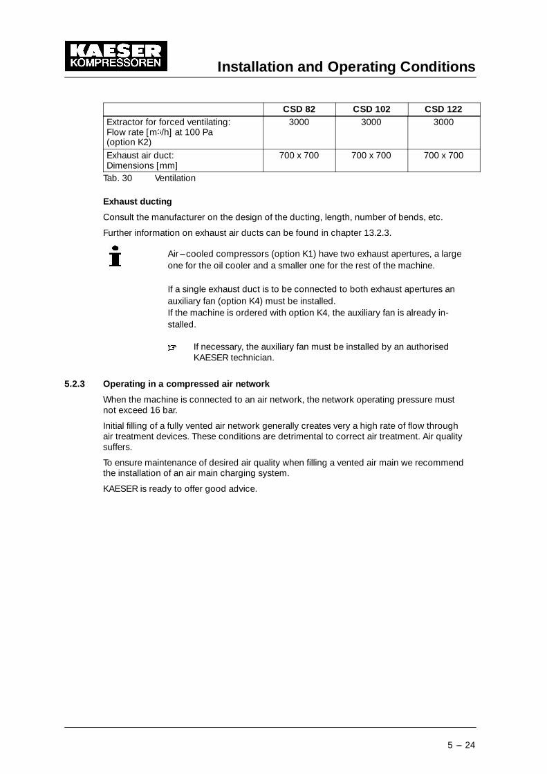
7.5 Pour Cooling Oil into the Inlet PortThe airend must be manually filled with cooling oil before initial start ---up and after beingout of use for more than 3 months.
Use the same type of oil.
A sticker giving the type of oil used is found near the oil separator tank filling port.
Fig. 12� � � � � � � � � � � � � � � � � � � � � �
1 Screw plug2 Inlet valve Remove the plug (1) from the inlet valve (2). Pour cooling oil into the airend.
Fig. 13 � � � � � � � 1 Compressor block 3 Cover2 Coupling 4 Rotational direction arrow

Initial Start---up
7 --- 31
� Remove the cover (3).� Note the rotational direction arrow (4).� Grasp the coupling (2) and turn it and the airend shaft (1).� Replace the coupling cover (3).
7.6 Checking Direction of RotationThe machine is designed for a clockwise field.� Check the supply with a phase sequence indicator.� If the compressor motor turns in the wrong direction, change the motor supply phases
L1 and L2.
Alternatively, the direction of rotation can be checked by briefly switchingthe machine on and off again.� Switch the machine off as soon as the direction of rotation is seen
and compare it with the direction arrows on the motor and airend.
7.7 Initial Start---up� Open the shut ---off valve to the air network.� Switch on at the main supply isolator.
The controller makes a self---test and the green LED ’Power ON’ (16) lights.� Press the ’Operating state LOAD/IDLE’ key.� Press the ’ON’ key (2).
The green LED ’Machine ON’ lights (1).� Allow the machine to idle for at least one minute.
This ensures good distribution of cooling oil.� Press the ’Operating state LOAD/IDLE’ key.
The machine switches to the LOAD state and delivers compressed air.
Watch for any faults occurring in the first hour of operation.
After the first 50 operating hours carry out the following:� Check that all electrical connections are tight.
7.8 Setting Network PressureThe network pressure (working pressure) is set at the works.
Adjustment is possible to suit individual operating conditions.� Network pressure setting is described in the SIGMA CONTROL service manual.
The machine may toggle a maximum of twice per minute between LOADand IDLE.
Reducing starting frequency:� Increase the difference between cut ---in and cut ---out pressure.� Add an air receiver downstream to increase buffer capacity.

Operation
8 --- 32
8 Operation
Fig. 14 Switching On and Off
1 ’Machine ON’ LED (green) 5 ’Remote’ key2 ’ON’ key (’I’) 6 ’LOAD’ LED3 OFF key (’0’) 7 ’IDLE’LED4 ’Clock’ key 8 ’Power ON’ LED (green)
13 LOAD / IDLE toggle key
8.1 Switching On and OffAlways switch the machine on and off with the ’ON’ and ’OFF’ keys.
The supply disconnecting device is installed by the user.
8.1.1 Switching on
Compressed air can cause serious injury!
Serious injury possible.� Never direct compressed air at a person or animal!� Ensure that:�no one is working on the machine,�all panels are in place,�all access doors are closed,�no parts of the machine are colder than + 3 ˚ C.� Switch on at the main supply isolator.
The controller makes a self---test and the green LED ’Power ON’ (16) lights.� Press the ’ON’ key (2).
The green LED ’Machine ON’ lights (1).
The compressor motor runs, assuming the network pressure is lower than the cut ---outpressure.
8.1.2 Automatic restart
Pre---condition: Network pressure is lower than cut ---out pressure.
Automatic restart is factory---set.
The machine restarts automatically when power is resumed after a power cut.
WARNING

Operation
8 --- 33
8.1.3 Switching off� Press the ’LOAD/IDLE’ toggle key (13).
The machine switches to IDLE and the LED (7) blinks.� After running in idle for 20 seconds, press the OFF key (3).
The ’Machine ON’ LED goes out (1).� Switch off and lock out the main supply isolator.
8.2 Switching Off in an Emergency and Switching On Again
Fig. 15 Switching off in an emergency
9 EMERGENCYSTOP button
Switching off� Press the ’EMERGENCY STOP’ button (9)
The ’EMERGENCY STOP’ remains latched in.
The machine pressure system is vented and the machine is prevented from re---starting.
Starting again
Pre---condition: Fault rectified.� Turn the ’EMERGENCY STOP’ button in the direction of the arrow to unlatch it.� Press the ’Reset’ key (11).� Switch the machine on.
8.3 Remote On and Off Switching
Pre---condition: Connection to a remote control device.� Press the ’Remote’ key (5).
The LED in the corner of the key lights. The remote control device has control of the ma-chine.
The machine can still be switched on and off by the ’ON’ and ’OFF’ keys (2 and 3) if re-quired.

Operation
8 --- 34
Apply the remote warning label to the machine where it is plainly visible.BEWARE! This machine is remotely controlled and can start at anytime.
Label the remote control device accordingly:”Before starting, make sure that no one is working on the mach ine andit can be safely started.”
8.4 Switching on and off with the Clock
Pre---condition: Clock programmed� Press the ’Clock’ key (4).
The LED in the corner of the key lights. The integrated clock has control of the machine.
Apply the time---controlled warning label to the machine where it is plainlyvisible.”BEWARE! This machine is clock---controlled and can start a t anytime.”
8.5 Acknowledging and Resetting Warning and Alarm Messages
Fig. 16 Acknowledging and Resetting Warning and Alarm Messages
10 ’Warning’ LED (yellow)11 ’Alarm’ LED (red)12 ’Acknowledge’ (reset) key
Alarm
An alarm shuts the machine down automatically. The red ’Alarm’ LED blinks (11).
Warning
The display shows a maintenance or warning message.
The yellow warning LED (10) blinks, for example, if a maintenance task is due.
8.5.1 Resetting alarm messages
Pre---condition: Fault rectified.

Operation
8 --- 35
� Press the ’Acknowledgement (reset)’ key (12).
The alarm LED (red) goes out (11).
The machine is now ready to start again.
8.5.2 Resetting warning messages
Pre---condition: The cause of the warning eliminated.Maintenance task completed.� Press the ’Acknowledgement (reset)’ key (12).
The warning LED (yellow) goes out (10).

Event Recognition and Fault Rectification
9 --- 36
9 Event Recognition and Fault Rectification
Inform KAESER service if the event cannot be rectified by the action suggested.
Do not attempt rectifications other than those given in this manual.
The measures valid for your machine are dependant on the individual equipment.
There are three types of event:
Description Indicated by see chapterAn event that triggers an alarm (with automaticshut ---down)
Blinking red LED 9.1
An event that triggers a warning (no shut ---down)
Blinking yellow LED 9.2
Miscellaneous events (faults) No indication 9.3
9.1 Alarms (machine shut---down, red LED blinking)
Message Possible cause Action KAESER servicetechnician only
access doors Door opened duringmachine operation.
Close the door(s).
ADT � Maximum airend di-scharge tempera-ture exceeded.
Ensure adequateventilation.
Ensure permittedroom temperaturenot exceeded.
Clean the cooler.
Cooling air outlet toonear a wall
Check the coolingoil level.
ADT dT/dt Maximum airend di-scharge tempera-ture rise rate excee-ded.
Check airend andpiping to airend.
Check the coolingoil level.
Check oil circulation.
airend rotation The motor is turningin the wrong direc-tion.
Changeover phaselines L1 and L2.
AI 1 open cct. Connection is bro-ken between thesystem pressuretransducer and ana-log input 1.
Short circuit toearth.
Check line and con-nection.
Check the sensor.
AI 2 open cct. Connection is bro-ken between the in-ternal pressuretransducer and ana-log input 2.
Short circuit toearth.
Check line and con-nection.
Check the sensor.

Event Recognition and Fault Rectification
9 --- 37
Message KAESER servicetechnician only
ActionPossible cause
AI 3 open cct. No connection be-tween the sensormeasuring airend di-scharge tempera-ture and the analoginput 3.
Check line and con-nection.
Check the sensor.
AI 4 open cct. No connection be-tween the sensormeasuring motortemperature and theanalog input 4.
Check line and con-nection.
Check the sensor.
AI 5 open cct. There is no connec-tion between thesensor allocated toanalog input 5 andthe input itself.
Short circuit toearth.
Check line and con-nection.
Check the sensor.
AI 6 open cct. There is no connec-tion between thesensor allocated toan analog input andthe input itself.
Short circuit toearth.
Check line and con-nection.
Check the sensor.
...
AI 8 open cct.
AI 1 short cct. The connection be-tween the sensorand the analog inputis shorted.
Check line and con-nection.
Replace defectivesensor.
...AI 8 short cct.back pressure Back pressure in the
oil separator tankcaused by poor ven-ting.
Check venting line. Check venting valve.
Check minimumpressure/checkvalve.
blowoff prot. The blowoff pres-sure of the pressurerelief valve on the oilseparator tank hasbeen exceeded.
Change the oil sepa-rator cartridge.
Open the shut ---offvalve in the ventingline.
Check the minimumpressure/checkvalve, the controlvalve and the inletvalve.
Check sensor, lineand connection.
condensate drain Fault in condensatedrainage.
Check condensatedrainage.
coolingwater low Cooling water pres-sure too low.
Check cooling watersupply.
Check that coolingwater shut ---off valveis fully open.

Event Recognition and Fault Rectification
9 --- 38
Message KAESER servicetechnician only
ActionPossible cause
EMERGENCYSTOP EMERGENCY STOPbutton pressed.
Unlatch the push-button.
ext. message 0 Rectify fault....
ext. message 5Fan M2 I � First fan motor shut
down because ofoverload.
Investigate cause.
Reset overload trip.
Fan M3 I � Second fan motorshut down becauseof overload.
Investigate cause.
Reset overload trip.
Fan M4 I � Third fan motor shutdown because ofoverload.
Investigate cause.
Reset overload trip.
HT cell Fault in the high ten-sion cell.
Check high tensioncell.
mains cont. off? The mains contactordoes not drop outdespite an OFFcommand.
Check auxiliary con-tact block.
Check 230 V avai-lable for the contac-tor.
mains cont. on? The mains contactordoes not pull in de-spite an ON com-mand.
Check auxiliary con-tact block on K1M.
Check 230 V avai-lable for the contac-tor.
mains monitor Fault in mains powersupply.
Have the mains po-wer supply checked.
model Machine model in-distinct
Re---enter modelname
Exchange controllermotor I � Drive motor shut-
down because ofoverload.
Change the oil sepa-rator cartridge.
Check minimumpressure/checkvalve.
Investigate cause.
motor T � Drive motor over-heated.
Ensure adequateventilation.
Install an extractor.
Clean the motor.motor bearings Drive motor bear-
ings overheated.Grease the motorbearings with thegreasing device.
Change motor bear-ings.
neutral p ---switch Rectify faultneutral T---switch Rectify fault

Event Recognition and Fault Rectification
9 --- 39
Message KAESER servicetechnician only
ActionPossible cause
no press. buildup Machine producesno compressed air.
The setpoint pres-sure does not riseabove 3.5 bar for apreset period.
Check for air leaks.
Check the coupling /V---belts.
Check the inletvalve.
Check minimumpressure/checkvalve.
Compare the ’inter-nal pressure’ indica-ted with the readingshown on the oil se-parator tank pres-sure gauge.
O 0.6/A 0.7 Short circuit in theline between outputO 0.6 or O 0.7 and aconsumer.
Check line and con-nection.
Check the consu-mer.
O 1.6/A 1.7 Short circuit in theline between outputO 1.6 or O 1.7 and aconsumer.
Check line and con-nection.
Check the consu-mer.
oil p � No changeover toload as long as theminimum oil pres-sure is not reached.
Check oil circulation.
Check pressureswitch, line and con-nection.
Replace defectiveswitch.
PD temperature � Compressor outlettemperature too low.
Check sensor, regu-lator.
Check the frequencyconverter.
PD temperature � Compressor outlettemperature toohigh.
Check the fan motor.
Clean the cooler.
Check the coolingoil level.
Check sensor, regu-lator.
Check the frequencyconverter.
Power supply � 2. Power failure Check power supplyvoltage.
Check door inter-lock.
pRV � The blowoff pres-sure of the pressurerelief valve on the oilseparator tank hasbeen exceeded.
Replace the pres-sure relief valve.
RD compr. p � Pressure switch onthe refrigerantcompressor activa-ted.
Ensure adequateventilation.
Clean the refrigerantcondenser.
Clean the cooler.
Replace defectivesensor.

Event Recognition and Fault Rectification
9 --- 40
Message KAESER servicetechnician only
ActionPossible cause
RD compr. T � Refrigerant comp-ressor overheating.
Clean the refrigerantcondenser.
Ensure adequateventilation.
Install an extractor.
Cleaning the cooler
RD compr. T � Refrigerant comp-ressor too cold.
Check refrigerationdryer.
separator dp � Oil separator cart-ridge clogged.
Replace the oil se-parator cartridge.
separator T � Maximum tempera-ture on oil separatortank outlet excee-ded.
Check the cutoutline.
Check the cutout onthe oil separatortank outlet.
SIGMA CONTROL T � SIGMA controllerhousing temperatureexceeded 70˚ C.
Ensure adequateventilation.
Ensure permittedroom temperaturenot exceeded.
Check control cabi-net ventilator (filtermats).
softstart Fault in the soft startsystem.
Check the soft startsystem.
start T � Air temperature atthe airend dischargeport too low.
Ambient tempera-ture below + 3˚ C.
Heat the compres-sor room.
Install auxiliary hea-ting.
V---belts broken The V---belts partedduring machine ope-ration.
Replace theV---belts.
VFD Frequency converterfaulty.
Check the frequencyconverter.
Tab. 32 Alarm messages and actions

Event Recognition and Fault Rectification
9 --- 41
9.2 Warning Messages (yellow LED blinking)
Message Possible cause Action KAESER servicetechnician only
access doors Doors opened dur-ing machine opera-tion.
Close access doors.
ADT � The maximum per-missible airend di-scharge tempera-ture will soon be re-ached.
Ensure adequateventilation.
Clean the cooler.
Cooling air outlet toonear a wall.
Check the coolingoil level.
Replace the oil filter.air filter dp � The pressure drop
across the air filter isrising.
Air filter elementclogged.
Clean/replace the airfilter element.
air filter h � The service intervalto the next air filterelement check hasexpired.
Clean/replace the airfilter element.
Bearingmaintenance h
� The service intervalto the next bearinggreasing has expi-red.
Grease the motorbearings.
blowoff prot. WarningThe blowoff pres-sure of the pressurerelief valve will soonbe reached.
Change the oil sepa-rator cartridge.
Open the shut ---offvalve in the ventingline.
Check the minimumpressure/checkvalve, the controlvalve and the inletvalve.
Check the pressuretransducer.
Buffer battery Data---retention bat-tery run down.
ContactKAESER service.
bus alarm The bus link fromthe Profibus DP in-terface is interrup-ted.
Check link and plug. Check the interfaceconfiguration.
condensatedrain Fault in condensatedrainage.
Check condensatedrain and lines.
elect. equip. h � The service intervalfor checking electri-cal equipment andwiring has expired.
Reset the service in-terval counter.
Check electricalcomponents.
ext.load signal? External load signalindistinct:Increased cut ---outpressure exceeded.
The external loadcontrol has notswitched to idle.
Check settings ofthe external control-ler.
Take the pressuredrops across filtersand dryer into ac-count.
Check discrepan-cies between pres-sure transducers.

Event Recognition and Fault Rectification
9 --- 42
Message KAESER servicetechnician only
ActionPossible cause
error: RS 485 Wrong configurationor transmission er-ror.
Bit rate and charac-ter frame for bothsubscribers identi-cal.
Check the link/inter-face connectionsbetween the twocontrollers.
Check maximumcable length andscreening.
Check interface pa-rameters.
1 master and 1 slaveconfigured.
ext. message 0 Rectify fault....
ext. message 5flash memory Internal controller
memory error.Exchange the cont-roller.
mains voltage � 1. power failure:Machine was re---started automati-cally.
Check power supplyvoltage.
Check door inter-lock.
modem problem SIGMA CONTROLdoes not recognisethe modem.
Check the link be-tween theSIGMA controllerand the modem.
motor T � Drive motor over-heating.
Ensure adequateventilation.
Install an extractor.
Clean the motor.motor bearings h � The service interval
to the next motorbearing change hasexpired.
Change motor bear-ings.
motorstarts /h � The permissiblenumber of motorstarts was exceededin the last 60 minu-tes.
Extend the idle pe-riod.
Increase capacity ofair receiver.
Increase cross---sec-tion of piping be-tween compressorand air receiver.
Check pressuretransducer.
Replace defectivesensor.
motor starts /d � The permissiblenumber of motorstarts was exceededin the last 24 hours.
Extend the idle pe-riod.
Increase capacity ofair receiver.
Increase cross---sec-tion of piping be-tween compressorand air receiver.
Check pressuretransducer.
Replace defectivesensor.
neutral p ---switch Rectify fault
neutral T---switch Rectify fault

Event Recognition and Fault Rectification
9 --- 43
Message KAESER servicetechnician only
ActionPossible cause
no press. buildup The compressorcannot build ---uppressure.
Check for air leaks.
Check the value gi-ven in the analogdata menu with thereading on the oilseparator tank pres-sure gauge.
Check the minimumpressure/checkvalve, the controlvalve and the inletvalve.
Check venting valve.
oil change h � The service intervalto the next oilchange has expired.
Change the coolingoil.
oil filter dp � Oil filter clogged. Change the oil filter.oil filter h � The service interval
to the next oil filtercheck has expired.
Change the oil filter.
oillevel � Oil level too low. Top up the coolingoil.
oil T � Cooling oil tempera-ture too low.
Increase room tem-perature.
Check the oil circuit.
Check temperaturegauge switch, lineand connection.
Replace defectiveswitch.
Install auxiliary hea-ting.
PD temperature � WarningCompressor outlettemperature is low.
Check sensor, regu-lator.
Check the frequencyconverter.
PD temperature � WarningCompressor di-scharge tempera-ture too high.
Clean the cooler.
Check the coolingoil level.
Check the fan motor.
RAM Internal RAM defec-tive.
Check controller.
Exchange the cont-roller.
Remaining oil con-tent � Warning
The purest class oilcontent limit willsoon be reached.
Check the scavengetube in the oil sepa-rator tank.
Check the dirt trapstrainer in the sca-venge line.
Check the oil sepa-rator cartridge.
Check oil sensor lineand connection.
Remaining oilcontent � The purest class oil
content limit is ex-ceeded.
Check the scavengetube in the oil sepa-rator tank.
Check the dirt trapstrainer in the sca-venge line.
Check the oil sepa-rator cartridge.
Check oil sensor lineand connection.
separator dp � Oil separator cart-ridge clogged.
Change the oil sepa-rator cartridge.

Event Recognition and Fault Rectification
9 --- 44
Message KAESER servicetechnician only
ActionPossible cause
separator h � The service intervalto the next oil sepa-rator cartridge checkhas expired.
Change the oil sepa-rator cartridge.
set output The ’set output’ testfunction is activated.
End the ”set output”mode.
System pressure � System pressurehas fallen below theset ’low’ value.
Air consumption toohigh.
Check air demand.
Check line and con-nection.
Check ’systpress.low’ setting.
Check pressuretransducer.
Replace defectivesensor.
System pressure �(vacuum machinesonly)
System pressurehas fallen below theset ’high’ value.
Check for air leaks.
Check ’syspress.high’ setting.
Check if the mac-hine switches toLOAD.
VFD mains Failure of powersupply to the fre-quency converter.
Check powersupply.
V---belt tension V---belt tension toolow.
Re---tension theV---belts.
V---belt tens. h � The service intervalto the next V---beltre---tensioning hasexpired.
Re---tension theV---belts.
Tab. 33 Warning messages and actions
9.3 Miscellaneous events (faults)
Alarm Possible cause Action KAESER servicetechnician only
Motor overload pro-tection relay trippedout.
Overload relay is de-fective or incorrectlyset.
Check setting. Replace the over-load relay.
out.Oil separator cart-ridge clogged.
Check pressuredrop across the se-parator cartridge.
Change the oil sepa-rator cartridge if ne-cessary.
The pressure sys-tem does not vent.
Open the shut ---offvalve in the venting
Check venting valve.The pressure sys-tem does not vent.
Open the shut ---offvalve in the ventingline.
Check minimumpressure/checkvalve.
Motor defective; be-aring damage orwindings shorted.
Check the motor.
Airend defective. Check the airend.

Event Recognition and Fault Rectification
9 --- 45
Alarm KAESER servicetechnician only
ActionPossible cause
Machine runs butproduces no comp-ressed air.
Inlet valve not ope-ning or only openingpartially.
Check the valve.
ressed air.Venting valve notclosing.
Check venting valve.
Pressure system lea-king.
Check pipework andconnections for le-aks and tighten.
The air demand isgreater than the ca-pacity of the comp-ressor.
Check air networkfor leaks.
Shut down the con-sumer(s).
Install auxiliarycompressor.
Hose coupling ormaintenance hosestill plugged into thequick---releasecoupling on the oilseparator tank.
Remove coupling ormaintenance hose.
Cooling oil runs outof the air filter.
Oil level in the sepa-rator tank too high.
Drain off oil until thecorrect level is reac-hed.
Inlet valve defective Check the valve.Compressor switc-hes between loadand idle more than
Air receiver toosmall.
Install an air receiverof sufficient capacity.hes between load
and idle more thantwice per minute.
Flow into the air net-work restricted.
Increase air line dia-meters.
Check filter ele-ments.
Oil leaking into thefloor pan.
Hose coupling ormaintenance hosestill plugged into thequick---releasecoupling on the oilseparator tank.
Remove coupling ormaintenance hose.
Oil cooler leaking Replace the oil coo-ler.
Connection leaking. Tighten connec-tions.
Replace seals.Cooling oil con-sumption too high.
Unsuitable oil used. Use SIGMA FLUIDcooling oil.sumption too high.
Oil separator cart-ridge split.
Change the oil sepa-rator cartridge.
Oil level in the sepa-rator tank too high.
Drain off oil until thecorrect level is reac-hed.
Oil return line clog-ged.
Check dirt trap inthe oil return line.
Tab. 34 Miscellaneous events (faults)

Maintenance
10 --- 46
10 Maintenance
10.1 Safety
Disregarding these notes and/or improper handling may resu lt in serious injury.
Electric shock can kill!
Touching electrically live components can cause serious injury or death.� Isolate completely from the mains supply (all conductors)(switch off at the main isolator)� Ensure the supply cannot be switched on again (lock off).� Check that no voltage is present.� Only work on electrical components when they are voltage---free.� Work carefully.� Before switching on again ensure that:�
no one is working on the machine,�all panels are in place and secured,�all access doors are closed.
There is considerable danger of injury or death from the rele ase ofspring force if spring--- loaded components are incorrectl y opened (dis-mantled).
Minimum pressure/check valves, pressure relief valves and inlet valves areunder powerful spring loading.� Do not open (dismantle) valves.
Compressed air can cause injury or death.
Serious injury or death can result from loosening or opening componentsunder pressure.� Close shut ---off valves or otherwise isolate the machine from the air
main to ensure that no compressed air can flow back into the ma-chine.� De---pressurize all pressurized components and enclosures.� Check all machine hose connectors with a hand---held pressure gaugeto ensure that all read zero.
Machine damage from leakage
Leaks result in loss of oil and reduced performance.
Damage or complete breakdown can result.� Test run after maintenance or service.� Carry out a visual check of the machine.
DANGER
WARNING
WARNING
CAUTION

Maintenance
10 --- 47
Maintenance work may only be carried out:�by persons trained in the machine and persons under the supervi-sion of an expert,�by experts,�by an authorised KAESER service agent.
Work on electrical devices may only be carried out in accordance with elec-trical regulations:�
by persons trained in the machine under the supervision of anelectrician,�by an electrician,�by an authorised KAESER service agent.
10.2 Maintenance Schedule
Maintenance intervals are recommendations only and should be adjustedto suit the installation and operating conditions.
According to the way a machine is equipped, sensors and/or maintenance intervalcounters monitor the operational state of important functional devices. Necessary mainten-ance tasks are signalled by the SIGMA controller.� Keep a log of all service work.
This enables the frequency of individual maintenance tasks to be compared withKAESER’s recommendations. A list is given in chapter 10.15.
10.2.1 Resetting maintenance interval counters
Maintenance interval counters indicate the operating hours between maintenance tasks.
When a maintenance task is completed, reset the corresponding counter to its originalvalue.
See the SIGMA CONTROL service manual.
Pre---condition: Maintenance task completed.Service message reset.Activate password level 4.� Select the appropriate entry from the maintenance menu.� Select ’reset’ and ’y’ and confirm with the enter key.

Maintenance
10 --- 48
10.2.2 Regular maintenance work
When operating conditions are unfavourable (e.g. dusty atmosphere) orwhen the equipment is heavily utilised, maintenance tasks must be carriedout more frequently (shorter intervals).� Heed controller maintenance messages.� Have KAESER service adjust the maintenance interval counters to
suit operating conditions.
Interval Maintenance tasks see chapterWeekly Check cooling oil level. 10.10.1Weekly
Clean or renew the filter mats. 10.3.2 / 10.6Every 1000 h Oil and air cooler maintenance. 10.3Every 1000 h
Heat recovery system maintenance. 10.4
Indicated bySIGMA CONTROL
Air filter maintenance. 10.5
Indicated bySIGMA CONTROLbut at least an-nually.
Change the oil filter. 10.12
Indicated bySIGMA CONTROLbut at least every3 years.
Change the oil separator cartridge. 10.14
Every 2000 h, but atleast annually.
Grease the motor bearings. 10.7
Every 3000 h Check the coupling. 10.8Variable (seebelow)
Change the cooling oil. 10.11
Annually Check that all electrical connections are tight.AnnuallyCheck the pressure relief valve. 10.13
Check the oil and air coolers for leaks. 10.3h = operating hours
Tab. 35 Regular maintenance work
10.2.3 Oil change intervals
The duty cycle and ambient conditions are important criteria for the number and length ofthe change intervals.
Coolant Maximum permissible oil change interval[operating hours / year]Favourable operating condi-tions*
Unfavourable operating condi-tions
SIGMA FLUID PLUS
SIGMA FLUID MOL
SIGMA FLUID FGL
SIGMA FLUID FGH
9 000 / 3
3 000 / 1
3 000 / 1
3 000 / 1
6 000 / 1
2 000 / 1
2 000 / 1
2 000 / 1* Cool to moderate ambient temperatures, low humidity, high duty cycle
Tab. 36 Oil change intervals

Maintenance
10 --- 49
10.2.4 Regular service work
Only authorised KAESER service agents should carry out service work.
When operating conditions are unfavourable (e.g. dusty atmosphere) orwhen the equipment is heavily utilised, service work must be carried outmore frequently (shorter intervals).
Interval Maintenance tasksUp to 12000 h Check valves.Up to 12000 h, atthe latest every3 years
Change the fan motor bearings or the motor complete.
Up to 36000 h, atthe latest every
Change the drive motor bearings.Up to 36000 h, atthe latest every8 years
Change the coupling.8 years
Change the hose lines.
Tab. 37 Regular service work

Maintenance
10 --- 50
10.3 Cooler Maintenance
10.3.1 Air cooling (option K1)
Material: brushvacuum cleaner
Pre---condition: Machine switched off.Mains isolator locked offMachine cooled down.
Check the cooler regularly for contamination. Frequency is mainly dependant on local op-erating conditions.
Contamination causes overheating and machine damage.
Avoid dust disturbance. Wear breathing apparatus if necessary.
Do not use sharp objects to clean the cooler. The cooler could be damaged.
A severely contaminated cooler should be cleaned by a KAESER service agent.
Fig. 17 Cleaning the cooler
1 Cooler2 Brush� Dry brush the cooler (1) and use a vacuum cleaner to suck up the dirt.
10.3.2 Filter mat maintenance (option K3)
Material: Warm water and household detergentSpare parts (as required)
Pre---condition: Machine switched off.Mains isolator locked offMachine cooled down.

Maintenance
10 --- 51
Fig. 18 Cooler filter mats
1 Filter mat2 Retaining frame3 Fixing
Removal� Unlock the fixings (3).Use a screwdriver to turn the fixing 90˚ anti---clockwise.� Remove the frame (2).
Cleaning� Beat the mat (1) or use a vacuum cleaner to remove loose dirt. If necessary, wash themat in lukewarm water and household detergent then rinse thoroughly.
Renew the mat if cleaning is not possible of has already been carried out five times.
Replacing� Replace the frame and close the fixings.Press and turn the fixings 90˚ clockwise until they latch.
10.3.3 Water cooling maintenance (option K2)
Pre---condition: Machine switched off.Mains isolator locked offMachine cooled down.
Check the cooler regularly for leaks and contamination. Frequency of checking is depend-ant on the characteristics of the cooling water.
Contamination causes overheating and machine damage.� Observe the airend discharge temperature to detect any tendency to rise.
Cleaning:� An authorised KAESER service agent should clean the cooler when the airend dis-charge temperature is 10 ˚ C above the annual average.
Leakage
Pressure in the cooling oil circuit is generally higher than that in the cooling water system.If a leak occurs, oil will run into the cooling water.� Check the cooler visually for leaks.� Have an authorised KAESER service agent check the cooler for internal leaks at least
once a year.

Maintenance
10 --- 52
10.4 Internal Heat Recovery Maintenance (option W2 / W3)
Pre---condition: Machine switched off.Mains isolator locked offMachine cooled down.
Deposits in the heat exchanger in machines with heat recovery systems can adversely af-fect heat transfer.
Check the heat exchanger regularly for leaks and contamination. Frequency of checking isdependant on the characteristics of the heat transfer medium.
Contamination� Have an authorised KAESER service agent clean the heat exchanger as soon as apressure drop in the heat transfer medium is detected.
Leakage
If a leak occurs, cooling oil can flow into the heat transfer medium as pressure the coolingoil circuit is generally higher.� Check the heat exchanger visually for leaks.� Have an authorised KAESER service agent check the heat exchanger for internal leaks
at least once a year.
10.5 Air Filter Maintenance.
Material: Compressed airSpare parts (as required)
Pre---condition: Machine switched offMains isolator locked offMachine cooled down.
Fig. 19 Air filter maintenance.
1 Retaining clip 3 Air filter cartridge2 Cover

Maintenance
10 --- 53
Open the air filter housing:� Pull the retaining clips (1) outwards and remove the cap (2).� Pull out the air filter cartridge (3) by turning lightly.� Clean the sealing surfaces and the air filter housing.
Do not wet---clean the air filter element.
Clean the air filter cartridge by tapping
Renew the cartridge after two years or after it has been cleaned five times.� Tap the cartridge on the end a number of times with the palm of the hand.� Clean the sealing faces.
Cleaning the air filter cartridge with compressed air� Use dry compressed air at not more than 5 bar to blow dirt from the air filter cartridgefrom inside to outside.
Close the air filter housing� Insert the filter cartridge.� Push on the housing and close the retaining clips.� Close all access doors and replace all cover panels.� Switch on the power supply and reset the maintenance interval counter.
10.6 Filter mat maintenance (control cabinet ventilator)
Material: Warm water and household detergentSpare parts (as required)
Pre---condition: Machine switched off.Mains isolator locked offMachine cooled down.
Fig. 20 Control cabinet ventilator
1 Ventilator grill2 Filter mat

Maintenance
10 --- 54
Removal� Remove the ventilator grill (1) and the filter mat (2).
Cleaning� Beat the mat or use a vacuum cleaner to remove loose dirt. If necessary, wash the matin lukewarm water and household detergent then rinse thoroughly.Renew the mat if cleaning is not possible of has already been carried out five times.
Replacing� Lay the filter mat in the frame and push on the grill to latch.
10.7 Electric motor maintenance
Material: Bearing greaseCleaning rags
Pre---condition: Machine running.
Hot components --- danger of burning� Wear long---arm clothing and gloves.� Work carefully.
Compressor motor
The motor bearings are fitted with grease nipples.
High---temperature grease ESSO UNIREX N3 should be used for re---greas-ing the motor bearings. Bearing damages caused by the use of otherbrands of grease are excluded from the warranty.
Fig. 21 Compressor motor maintenance
1 Grease nipple� Clean the grease nipple (1) with a rag.
Apply the quantity of grease as given on the motor nameplate.� Grease both bearings.� Close all access doors; replace and secure all removable panels.� Switch on the machine and reset the maintenance interval counter.
Fan motor
Fan motor bearings are permanently greased and need no further greasing.
CAUTION

Maintenance
10 --- 55
10.8 Checking the Coupling
Danger of injury from rotating coupling!
Severe injury could result from touching the coupling while it is rotating.� Never switch the machine on without the guard in place over thecoupling.
The coupling must be carefully inspected at regular intervals.
A defective coupling is recognisable by:�noisy running,�surface cracks,�colour change.
Fig. 22 Checking the Coupling
1 Safety screen2 Coupling
Check for uneven or noisy running� Switch the machine on.� Check the coupling (2) for noisy or uneven running.
Check for damage
Pre---condition: Machine switched off.Mains isolator locked offMachine cooled down.� Remove the fixing screws from the safety screen (1).� Turn the coupling my hand and look for damage or colour change.� Have a damaged coupling changed by an authorised KAESER Service agent.� Refit the safety screen.� Close all access doors and replace all cover panels.
WARNING

Maintenance
10 --- 56
10.9 Venting the Machine Manually
Pre---condition: Machine switched off.Mains isolator locked offMachine cooled down.
Compressed air can cause injury or death.
Compressed air and devices under pressure can injure or cause death ifthe contained energy of the air is released suddenly or uncontrolled.
After shutting down the compressor and venting the oil separator tankthere is still pressure on the check valve from the air main.� Close the shut ---off valve provided by the user to isolate the machine
from the air main.� Vent the oil separator tank.� Vent the air aftercooler to completely depressurise the system betweenthe user’s shut ---off valve and the minimum pressure/check valve.
Escaping oil mist is damaging to health.� Do not direct the maintenance hose at a person while venting.� Do not inhale oil mist or vapour.� Avoid contact with skin and eyes.
Before undertaking any maintenance or service work on the pressure system the machinemust be isolated from the air system and completely vented.
The machine is vented in three stages:�the oil circuit vents automatically when the machine is switched off,�air is vented manually from the oil separator tank,�air is vented manually from the air cooler.
Venting� Close the user’s shut ---off valve between the machine and the air main.
If no shut ---off valve is provided, the complete air system must be vented.
The hose coupling, shut ---off valve and maintenance hose lie beneath theoil separator tank.
WARNING
CAUTION

Maintenance
10 --- 57
Fig. 23 Ventilate the machine.
1 Hose coupling (air cooler venting) 6 Male hose coupling/fitting2 Pressure gauge 7 Shut---off valve
A: closedB: open
3 Hose coupling (oil separator tank ven-ting)
8 Maintenance hose� Check that the oil separator tank pressure gauge reads zero.
After automatic venting the pressure gauge does not read zero?� Make sure that the shut ---off valve is closed.� If manual venting does not bring the oil separator tank pressure gaugeto zero, call KAESER service.
Manually venting the oil separator tank� With the shut ---off valve closed, insert the male hose fitting (6) into the hose coupl-ing (3).� Open the shut ---off valve (7) slowly to release pressure.� Withdraw the male hose fitting and close the shut ---off valve.
Manually venting the compressed air cooler� With the shut ---off valve closed, insert the male hose fitting (6) into the hose coupl-ing (1).� Open the shut ---off valve (7) slowly to release pressure.� Withdraw the male hose fitting and close the shut ---off valve.
10.10 Checking and Topping up the Cooling Oil
10.10.1 Check cooling oil level.
Pre---condition: Machine has been running at least five minutes under load.(minimum 50 Hz for machines under frequency control).
Danger of burning from hot surfaces!
Skin burns are possible.� Wear long---arm garments and protective gloves.� Work carefully.
CAUTION

Maintenance
10 --- 58
Fig. 24 Check cooling oil level.
2 Oil separator tank min Minimum oil level3 Oil level indicator OK Oil level optimum4 Indicator markings max Oil level maximum5 Green zone� Readout oil level.
When the indicator shows minimum level, top up the oil.
10.10.2 Topping up the cooling oil
Material: Cooling oil
Pre---condition: Machine switched offMains isolator locked offMachine cooled down.
Danger of explosion from oils and lubricants!
Danger of explosion from oil mist and vapours.� Fire, naked flame and smoking are forbidden!
Damage to the machine from unsuitable oil� Never mix different types of oil.� Top up only with the same type of oil as already in the machine.
Venting� Close the user’s shut ---off valve between the machine and the air main.
If no shut ---off valve is provided, the complete air system must be vented.
The hose coupling, shut ---off valve and maintenance hose lie beneath theoil separator tank.
WARNING
CAUTION

Maintenance
10 --- 59
Fig. 25 Topping up the cooling oil
1 Hose coupling (air cooler venting) 5 Oil level indicator2 Pressure gauge 6 Male hose coupling/fitting3 Hose coupling (oil separator tank ven-
ting)7 Shut---off valve
A: closedB: open
4 Oil filling port with plug 8 Maintenance hose� Check that the oil separator tank pressure gauge (2) reads zero.
After automatic venting the pressure gauge does not read zero?� Make sure that the shut ---off valve is closed.� If manual venting does not bring the oil separator tank pressure gaugeto zero, call KAESER service.
Manually venting the oil separator tank� With the shut ---off valve closed, insert the male hose fitting (6) into the hose coupl-ing (3).� Open the shut ---off valve (7) slowly to release pressure.� Withdraw the male hose fitting and close the shut ---off valve.
Manually venting the compressed air cooler� With the shut ---off valve closed, insert the male hose fitting (6) into the hose coupl-ing (1).� Open the shut ---off valve (7) slowly to release pressure.� Withdraw the male hose fitting and close the shut ---off valve.
Topping up the cooling oil� Open the filler plug (4) slowly.� Top up the cooling oil.� Replace the plug gasket if necessary and re---insert the plug.
Start the machine and carry out a test run� Close all access doors; replace and secure all removable panels.� Open the user’s shut ---off valve between the machine and the air main.� Start the machine and allow it to idle for at least one minute. Then switch to LOAD.� After about five minutes, check the oil level and top up if necessary.� Carry out a visual check for leaks.

Maintenance
10 --- 60
10.11 Changing the Cooling Oil
Material: Cooling oilHave the oil container ready.
Thoroughly drain the oil from the separator tank, the cooler and the heat recovery system iffitted.
Dispose of the old oil in accordance with local environment p rotectionregulations.
Danger of burning from hot components and oil.� Wear long---arm clothing and gloves.� Work carefully.
Fig. 26 Changing the Cooling Oil, Oil Separator Tank
1 Hose coupling (air cooler venting) 6 Male hose coupling/fitting2 Pressure gauge 7 Shut---off valve
A: closedB: open
3 Hose coupling (oil separator tank ven-ting)
8 Maintenance hose
4 Oil filling port with plug 9 Hose coupling (oil drain)5 Oil level indicator 10 Shut---off valve (venting line)
11 Shut---off valve (oil drain)Compressed air helps to expel the oil.
This pressure can be generated by the machine itself.
Alternatively, an external source of compressed can be used.
External air is necessary when:�the machine is not operational�the machine is to be restarted after a long standstill period.
Oil changing with help from internal pressure
Pre---condition: Machine has been running at least five minutes under LOAD.Machine is switched off.Machine fully vented (no pressure).Pressure gauge on the oil separator tank indicates zero.
CAUTION

Maintenance
10 --- 61
� Close the shut ---off valve (10) in the venting line.� Start the machine in idle and watch the oil separator tank pressure gauge (2) until itreads 3---5 bar.� Switch the machine off.� Switch off and lock out the main supply isolator.� Wait at least two minutes for oil to flow back to the separator tank.
Alternative: Oil changing with help from an external pressu re source
Pre---condition: Machine switched off.Mains isolator locked offMachine fully vented (no pressure).Pressure gauge on the oil separator tank indicates zero.External source of compressed air available.� Close the shut ---off valve (10) in the venting line.� With the shut ---off valve closed, insert the male hose fitting (6) into the hose coupl-
ing (3).� Connect the maintenance hose to an external air supply.� Open the shut ---off valve (7) until the pressure gauge on the oil separator tank reads3---5 bar.� Close the shut ---off valve (7) and withdraw the hose fitting from the coupling.
Draining the oil from the separator tank
Contact KAESER service if condensate is detected in the oil.It is necessary to adjust the airend discharge temperature to suit operatingconditions.� Have the oil container ready.� With the shut ---off valve closed, insert the male hose fitting (6) into the hose coupl-
ing (9).� Place the end of the maintenance hose in the oil container and secure it in place.� Open the shut ---off valve (11).� Open the shut off valve (7) in the maintenance hose slowly and close when air es-capes.� Close the shut ---off valve (11) and unplug the hose.

Maintenance
10 --- 62
Draining the oil from the cooler
Fig. 27 Changing the Cooling Oil
1 Oil cooler 6 Male hose coupling/fitting2 Hose coupling (oil drain) 7 Shut---off valve3 Shut---off valve� Have the oil container ready.� With the shut ---off valve closed, insert the male hose fitting (6) into the hose coupl-
ing (2).� Place the end of the maintenance hose in the oil container and secure it in place.� Open the shut ---off valve (3).� Open the shut ---off valve (7) slowly and allow oil and air to drain completely.� Check that the oil separator tank pressure gauge reads zero.� Close the shut ---off valve (2) and unplug the hose.
Filling with cooling oil� Open filler plug (4, Fig. 26) slowly.� Fill with oil.
Machines with heat recovery systems need correspondingly more oil.� Check the plug and gasket for damage and re---insert the plug.
Start the machine and carry out a test run� Close all access doors; replace and secure all removable panels.� Open the user’s shut ---off valve between the machine and the air main.

Maintenance
10 --- 63
� Switch on the power supply and reset the maintenance interval counter.� Allow the machine to idle for at least one minute. Then switch to LOAD.� After about five minutes, check the oil level and top up if necessary.� Carry out a visual check for leaks.
10.12 Oil filter maintenance
Material: Spare partsHave the oil container ready.
Pre---condition: Machine switched offMains isolator locked offMachine fully vented (no pressure).Pressure gauge on the oil separator tank indicates zero.
Danger of burning from hot components and oil.� Wear long---arm clothing and gloves.� Work carefully.
Fig. 28 Changing the Oil Filter
1 Oil filter2 Direction to unscrew
Dispose of parts and materials contaminated with oil in acco rdancewith local environment protection regulations.� Unscrew the oil filter anti---clockwise, catch oil spillage and dispose of correctly.� Lightly oil the new oil filter gasket.
Screw on the new filter using hand pressure only. Do not use any tool.� The oil filter is turned clockwise to tighten.
CAUTION

Maintenance
10 --- 64
Start the machine and carry out a test run� Close all access doors; replace and secure all removable panels.� Open the user’s shut ---off valve between the machine and the air main.� Switch on the power supply and reset the maintenance interval counter.� Allow the machine to idle for at least one minute. Then switch to LOAD.� After about five minutes, check the oil level and top up if necessary.� Carry out a visual check for leaks.
10.13 Checking the Pressure Relief Valve.
Pre---condition: Machine switched off.Activate password level 4.
In order to check the pressure relief valve, the machine’s working pressure is raised abovethe blowoff pressure of the valve.
There is danger of bursting if the permissible working press ure is ex-ceeded.
Noise from the pressure relief valve blowing off. Danger of scalding fromhot oil. Danger of injury from bursting components or the release of com-pressed air.� Close all access doors; replace and secure all removable panels.� Wear ear and eye protection.� Work carefully.� Abort the test if the working pressure reaches 10% above the blowoff
pressure of the valve.
Carry out the test exactly as described in the SIGMA CONTROL manual.
Blowoff protection and system pressure monitoring are switched off duringthe test.The machine may only be operated with a correctly functioning pressurerelief valve.� Close the user’s shut ---off valve between the machine and the air main.� Observe the pressure indicator on the SIGMA controller and call up the test function.� Stop the test as soon as the pressure relief valve blows off or working pressure re-
aches 10% above the blowoff set point.� Replace a defective pressure relief valve.� Deactivate the test function.� Open the user’s shut ---off valve between the machine and the air main.
WARNING

Maintenance
10 --- 65
10.14 Changing the Oil Separator Cartridge
Material: Spare partsPrecision pressure gaugeCleaning rags
Pre---condition: Machine switched off.Mains isolator locked offMachine fully vented (no pressure).Pressure gauge on the oil separator tank indicates zero.Machine cooled down.
The life of the oil separator cartridge is influenced by:�contamination in the air drawn into the compressor,�adherence to the schedule of oil and air filter changes,
Fig. 29 Changing the Oil Separator Cartridge
14 Cover 19 Pipe fitting15 Dirt trap 20 Fitting16 Air pipe 21 Gasket17 Retaining screw 23 Oil separator cartridge
25 Minimum pressure/check valve� Unscrew the fitting (20) and carefully put the parts to one side; pull out the copperpipe at item (15).� Unscrew the fittings (19) from the ends of the air pipe (16).� Withdraw the air pipe from the minimum pressure/check valve (25) and push carefullyto one side.� Remove the cover retaining screws (17) and carefully lift the cover (14).
The oil separator element cannot be cleaned.

Maintenance
10 --- 66
Dispose of parts and materials contaminated with oil in acco rdancewith local environment protection regulations.� Take out the old oil separator element (23) together with the gaskets (21) and dispose
of according to environmental regulations.� Wipe all sealing faces with a cleaning rag.� Insert the new oil separator cartridge with gaskets and re---fix the cover.� Renew the dirt trap (15) strainer and O---ring.� Connect the air pipe to the minimum pressure/check valve.� Replace and tighten all fittings.
Start the machine and carry out a test run� Close all access doors; replace and secure all removable panels.� Open the user’s shut ---off valve between the machine and the air main.� Switch on the power supply and reset the maintenance interval counter.� Allow the machine to idle for at least one minute. Then switch to LOAD.� Carry out a visual check for leaks.

Maintenance
10 --- 67
10.15 Logging Maintenance Work
Machine number:
Date Maintenance task carried out Operating hours Signature
Tab. 38 Maintenance log
Spares, Operating Materiels, Service
11 --- 68
11 Spares, Operating Materials, Service
11.1 Note the nameplate
Take data from the nameplate for all enquiries and spare parts orders.
11.2 Ordering Maintenance Parts and Operating Materials
Personal injury or machine damage may result from the use of u nsuit-able spare parts or operating materials.
Unsuitable or poor quality maintenance parts and operating materials maydamage the machine or impair its proper function.
Damage to the machine can also result in personal injury.� Use only genuine spare parts and authorised operating materials.� Have an authorised KAESER service agent carry out regular mainten-ance.
KAESER maintenance parts and operating materials correspond to the original. These arecorrect for use in our machines.
Compressor
Name Quantity material numberAir filter cartridge 1 1250
Filter mat, control cabinet fan 2 1100
Filter mat (cooler) 1 1050Oil filter 1 1200
Oil separator cartridge 1 1450
Cooling oil 1 1600
Bearing grease [g] 100 9.0915.0Bearing grease [g]
400 6.3234.0Tab. 39 Machine maintenance parts
11.3 Maintenance Contract� Sign a maintenance contract with an authorised KAESER service agent.
This ensures the utmost reliability and availability of your compressed air supply system.
11.4 Service Addresses
Address of KAESER agents are given at the end of this manual.
11.5 Spare Parts for Service and Repair
These spare parts lists are intended for trained personnel.
They contain important information for preventive service.
Service and repair work not described in the this manual should only becarried out by a KAESER service workshop or one authorised by KAESER.
CAUTION


De---commissioning, Storage and Transport
12 --- 75
12 De---commissioning, Storage and Transport
12.1 De---commissioningDe---commissioning is necessary when:�
the machine will not be needed for some time,�the machine is to be moved to another location,�the machine is no longer needed,�the machine is to be scrapped.
Temporarily out of service
Pre---condition: The machine can be started at regular intervals.� Run the machine once a week under load for at least 30 minutes to ensure corrosionprotection.
Out of service for a considerable period
Pre---condition: When running for the last time before taking out of service the machineshould have run under load for at least 30 minutes.Machine switched off and fully vented.Main supply isolator switched off and locked.� Allow the machine to cool down completely.� In water---cooled machines, disconnect the water supply and drain all water from the
machine.� Disconnect all air and electrical connections.
12.2 Packing
Material: DesiccantPlastic sheetingWooden transport crate
Pre---condition: Machine is de---commissioned.Machine dry and cool.� Place desiccant inside the machine cabinet.� Wrap the machine in plastic sheeting.
Transport packing
A wooden crate is required for overland transport to protect the machine from mechanicaldamage.
Consult an authorised KAESER service agent for advice on packing for sea or air transport.
12.3 Storage
Pre---condition: The machine is adequately packed.� Store the machine in a dry, frost ---free room.� Prevent entry of moisture and condensation.

De---commissioning, Storage and Transport
12 --- 76
12.4 TransportingUse only a fork truck or lifting cradle.
Take weight and centre of gravity into consideration. The centre of gravity is shown in thedrawing in chapter 13.2.3.
The water cooling system of water---cooled machines must be drainedcompletely if there is danger of frost.
Fork truck
Pre---condition: The whole machine is over the forks.
Fig. 30 Transport by fork truck
Lifting cradle
Pre---condition: No pressure on the sides of the machine cabinet.
Fig. 31 Transport by lifting cradle
12.5 Disposal
Pre---condition: Machine is de---commissioned.
When disposing of a machine, drain out all liquids and remove dirty filters.
Parts contaminated with cooling oil must be disposed of in ac cordancewith local environment protection regulations.� Completely drain the cooling oil from the machine.� Remove used ail filter and separator cartridge.� Hand the machine over to an authorised disposal expert.

Annex
13 --- 77
13 Annex
13.1 Conformity
Machines with CE mark conform to European directives and may be operated in the EU.
A Declaration of Conformity is provided with the machine.
13.2 Diagrams and Drawings
13.2.1 Pipeline and instrument flow diagram (P&I diagrams)


Appendix
13 --- 83
13.2.2 Pipeline and instrument flow diagram (option C1)


Appendix
13 --- 89
13.2.3 Dimensional drawing
13.2.3.1 Air cooling (option K1)


Appendix
13 --- 92
13.2.3.2 Water cooling (option K2)


Appendix
13 --- 95
13.2.4 Electrical diagram