Embed Size (px)
Citation preview

Service Manual – MAXIMA UV Page 1 of 14
Strictly confidential – For internal use only
SERVICE MANUAL – MAXIMA UV
Prepared by: Eureka Forbes Limited, THQ Centre
Product Name: MAXIMA UV(GWPDMAXUV00000)
Project Number: SM-CL-003-2016-2017
Document Date: 04.08.2016
Revision No. & Date : None

Service Manual – MAXIMA UV Page 2 of 14
Strictly confidential – For internal use only
INDEX
# Description
1 Product details
2 Product Concept
3 Technical Specifications
4 Water Flow diagram
5 Wiring Diagram
6 Visual Indications
7 Major components and its functions
8 Packing List
9 Product Inspection & installation
10 Working Procedure of the product
11 Exploded view and part list
12 Care during service
13 Membrane cleaning by DBR
14 AMC Policy
Service Manual – MAXIMA UV Page 3 of 14
Strictly confidential – For internal use only
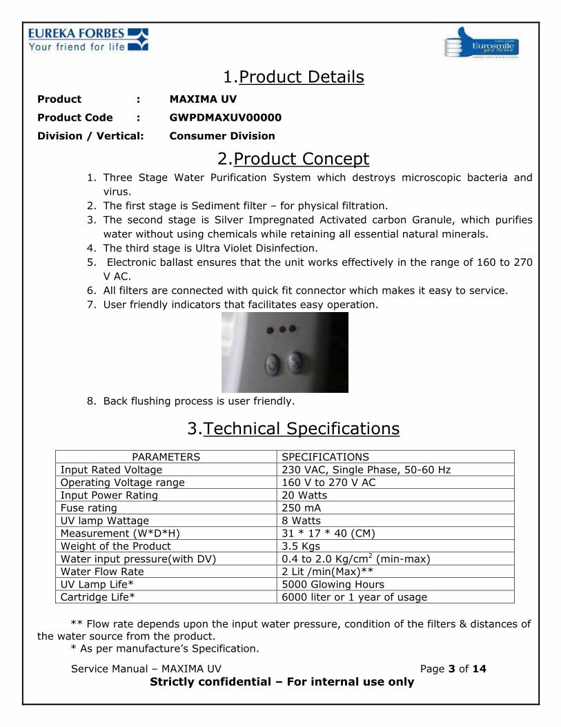
1.Product Details
Product : MAXIMA UV
Product Code : GWPDMAXUV00000
Division / Vertical: Consumer Division
2.Product Concept 1. Three Stage Water Purification System which destroys microscopic bacteria and
virus.
2. The first stage is Sediment filter – for physical filtration.
3. The second stage is Silver Impregnated Activated carbon Granule, which purifies
water without using chemicals while retaining all essential natural minerals.
4. The third stage is Ultra Violet Disinfection.
5. Electronic ballast ensures that the unit works effectively in the range of 160 to 270
V AC.
6. All filters are connected with quick fit connector which makes it easy to service.
7. User friendly indicators that facilitates easy operation.
8. Back flushing process is user friendly.
3.Technical Specifications
PARAMETERS SPECIFICATIONS
Input Rated Voltage 230 VAC, Single Phase, 50-60 Hz
Operating Voltage range 160 V to 270 V AC
Input Power Rating 20 Watts
Fuse rating 250 mA
UV lamp Wattage 8 Watts
Measurement (W*D*H) 31 * 17 * 40 (CM)
Weight of the Product 3.5 Kgs
Water input pressure(with DV) 0.4 to 2.0 Kg/cm2 (min-max)
Water Flow Rate 2 Lit /min(Max)**
UV Lamp Life* 5000 Glowing Hours
Cartridge Life* 6000 liter or 1 year of usage
** Flow rate depends upon the input water pressure, condition of the filters & distances of the water source from the product.
* As per manufacture’s Specification.

Service Manual – MAXIMA UV Page 4 of 14
Strictly confidential – For internal use only
4.WATER FLOW DIAGRAM – MAXIMA UV

Service Manual – MAXIMA UV Page 5 of 14
Strictly confidential – For internal use only
5.WIRING DIAGRAM – MAXIMA UV

Service Manual – MAXIMA UV Page 6 of 14 Strictly confidential – For internal use only
6. Visual indication
1. Red LED (solid) indicates the POWER ON.
2. Yellow LED (solid) indicates the unit in PROCESS.
3. Green LED (solid) indicates the unit is READY.
4. After ready indication the single beep buzzer comes on.
5. Lamp Current Sensing (LCS) detects the Ultra Violet Lamp connectivity
6. Failure of the lamp is detected by audio and visual indication (Blinking of the Yellow LED
and continuous Buzzer beeps).
7.MAJOR COMPONENTS & their FUNCTIONS
1st Sage – Sediment Filter :
The water passes thru the sediment filter which incorporates a specially developed 10” long melt blown Polypropylene fiber candle, which strains out physical impurities present in the
water, such as dust , dirt & mud. 2nd Stage – Silver Impregnated activated carbon Block:
The Water passes through the specialyy treated silver impregnated activated carbon, which
reduces colour, odour, organic impurities & free gases like chlorine. 3rd Stage – UV disinfection chamber
In third stage water is subject to ultra-violet radiation which has been documented as proven
technology for eleminating water borne desease causting Bacteria viruses. The ultravoilet germicidal dosage is even at its lowest, i.e., 1.2 times of that is rquired to destroy all known wter borne deisease-causing organisesm.
The major components are as below:

Service Manual – MAXIMA UV Page 7 of 14 Strictly confidential – For internal use only
Solenoid valve: Water flow, and power on/off swich:
PCB:
It is An in-built electronic circuit which stops water flow immediately, if the purification is inadequate. Thereby ensuring purified water or no water. Auto Shut Off, in which UV lamp
will shut off if water is not drawn for 10 minutes. Thus enhancing the life of UV lamp. Protection for SV short, when SV fails as short,UV lamp & SV goes Off, yellow LED will start blinking with beep sound, To recover from this condition, AC input has to be turned off &
turned ON again
# Snap shot of the part Part Code & Description
1
Part Name : FRONT COVER - SMART UV Part Number : GWPBSMTUV00005
Standard : Standard part which is used in SMART UV MODEL

Service Manual – MAXIMA UV Page 8 of 14 Strictly confidential – For internal use only
2
Part Name : BACK COVER - AS SMART UV Part Number : GWPBSMTUV00010 Standard : Standard part which is used in
SMART UV model
3
Part Name : TRAY & TRAY COVER –SMART UV
Part Number : GWPBSMTUV00095 & GWPBSMTUV00090
Standard : Standard part which is used in SMART UV MODEL.
4
Part Name : SOLENOID VALVE Part Number : GWPMSTRDX10055 Standard : Standard which is used in the Smart
UV & Etc.,
6
Part Name: REFLECTOR ALUMINIUM HOUSING FOR 8 WATT NEW
Part Number: GWPGAGNEO00390
Standard : Standard part which is used in AG NEO UV, enhance UV and other models
Material : Aluminium
7
Part Name: QUARTZ TUBE 22 x 25 x 281MM
Part Number: GWPMAGNEO00380 Material : Quartz Glass
8
Part Name: UV Lamp G 8 T5 Part Number: GWPMCLASI00380

Service Manual – MAXIMA UV Page 9 of 14 Strictly confidential – For internal use only
9
Part Name : SMPS PCB ASSY – FAF DLX Part Number : GWPMAFLDX10245 Standard : Standard part which is used in
AQUAFLO DX UV MODEL
10
Part Name : CHEMI BLOCK FILTER ASSY Part Number : GWPBENHUV10055 Standard : Standard part which is used in
ENHANCE RO MODEL Material : Coconut shell based activated carbon
with antimicrobial property and PP housing
11
Part Name : CLARITY CARTRIDGE ASSEMBLY
(5/16")
Part Number : GWPMENHUV30006 Standard : Standard part which is used in
magna models Material : PP Yarn candle and PP Housing
12
Part Name: DIVERTER VALVE ASSY PL4
Part Number: GWPMCOMMO10665 Suitable for 5/16” tube
Back flushing of clarity cartridge:
1. fix the PL tube one end into the DV.
2. Insert the other end of white colored PL tube to the unit inlet.
3. Disconnect the blue colored drain dummy plug from the unit.
4. Connect the blue colored PL tube to the Drain.
5. Switch ON the unit and run the water with full pressure from 10 minutes.
6. Connect tubes back into original position for normal usage.
7. Turn on the unit and drain out water for 1-2 minutes and then use the unit.

Service Manual – MAXIMA UV Page 10 of 14 Strictly confidential – For internal use only
8. Packing List
GWPBSMTUV00090 TRAY - MAXIMA UV 1 NOS
GWPBSMTUV00095 TRAY COVER - MAXIMA UV 1 NOS
GWPBMAXUV00835 Z CARD - MAXIMA UV 1 NOS
GWPBSTRLX00085 TRAY DRAIN CAP - STAR LX / DX 1 NOS
GWPBGENUS00650 INSTALLATION SCREW – GENEUS 2 NOS
GWPBGENUS00655 INSTALLATION SCREW INSERT – GENEUS 2 NOS
GWPMCOMMO10665 DIVERTER VALVE ASSY - PL4 1 NOS
GWPBREVIV00265 PL 4 TUBE WHITE COLOUR 1.5 M
GWPBREVIV00270 PL 4 TUBE BLUE COLOUR 1.5 M
GWPBCOMUV00809 PLUMBING KIT STICKER-UV (60*80 MM) 1 NOS
GWPBPRTUV00020 END PLUG PL4 WHITE 1 NOS
GWPBSMART10040 1/4" BSPX1/4" QUICK ST CONNECTOR (WHITE) 1 NOS
9. Inspection of Product & Installation
Inspect the unit as below given and make the product ready for installation: Unpack the unit from carton and check for contents
Inspect the unit for finish and ensure that there are no external damages
Check internals and ensure that there are no damages
The Service Person should understand the function of various key components & unit before commencing the installation.
Preparation of product for installation\
Finalize the location in consultation with the customer for the product to be installed.
Ensure that the location of the product is finalized such that no sunlight / excess heat falls on
the product.
Ensure that there are water & power connections available, where product is proposed to
install. Both should be in the range of one meter.
Mark the location of the installation with the help of the installation template sticker provided
along with the product. Drill holes and fix the installation screws along with inserts.
Decide the water source where the product to be installed and ensure that the power source
is also available near the point.
Ensure that there are water & power connections available, where product is proposed to
install. Both should be in the range of one meter.
Close the input water supply to the source point. Remove the existing tap and fix the Diverter
valve, fix the tap which is removed from the source point to the other end of the Diverter
valve.

Service Manual – MAXIMA UV Page 11 of 14 Strictly confidential – For internal use only
Open the water source and ensure that there are no leakages and the pressure is more than
0.6 kg/sq. cm. In case the pressure is more than 2 Kg/ sq. cm it is mandatory to install the
product only with PRV (available at additional cost).
Connect the 1/4” while tube, provided in the installation kit to the nozzle of Diverter valve
Flush the I cartridge adequately by connecting the filter to the other end of the Diverter valve
Place the product in a convenient place to prepare for installation
There are 2 ports on right side of the product like inlet and flushing
Connect the other end of the tube from I cartridge to the inlet port of the product after
removing the dummy plug used on the inlet port
Remove the dummy plug used on the flushing port and keep it safe
Connect the additional tube to the flushing port and keep the other end of the tube in the
sink. Now, open the Diverter valve so that the I-cartridge and pre carbon filter will be
flushed.
Flush both the cartridges adequately for 5 to 10 minutes. Close the Diverter valve (water
supply to the product); remove the tube from flushing port. Replace the plug in to the
flushing port.
Insert the Power Adaptor to the DC Power IN socket provided with the product and plug it
with 230 V AC power socket
Now the Product is ready for installation
Mount the product on the wall where the installation screw is fitted
Connect the other end of the tube (connected to the Diverter valve) to the inlet of the
product
Ensure the routing is proper by adjusting the tube length. If necessary cut the tube
Switch on the Power and open the water source to the product
Now the product installation is completed and the product will start working as per the
product function
Refer the Working Procedure of the product for details
10. WORKING PROCEDURE
Customer Interface Process:
1. When the unit is switched on the RED LED indicates the POWER ON. YELLOW LED (solid)
will be on for 59 sec. indicating self-check/sterilization of UV reactor water.
2. After 60 seconds GREEN LED (solid) will light up along with single beep indicating unit is ready to dispense safe drinking water.
3. Press Water switch to dispense water from the system.
Important Note: whenever the new cartridges are replaced, proper flushing and fixing is important and refer preparation / installation procedure of the product

Service Manual – MAXIMA UV Page 12 of 14 Strictly confidential – For internal use only
11. Exploded View

Service Manual – MAXIMA UV Page 13 of 14 Strictly confidential – For internal use only
12. SPARE LIST
# Component no. Object description Qty UOM
1 GWPBSTRLX00085 TRAY DRAIN CAP - STAR LX / DX 1 NOS
2 GWPBSMTUV00090 TRAY - AS SMART UV 1 NOS
3 GWPBCLBOO00908 PH PAN HD SCREW M4 X 15 7 NOS
4 GWPBSMTUV00095 TRAY COVER - AS SMART 1 NOS
5 GWPBSMTUV00005 FRONT COVER - AS SMART UV 1 NOS
6 GWPBCLASI00410 SPOUT CAP ( FACIA) 1 NOS
7 GWPBSMTUV00410 OUTLET SPOUT SET (SMART) 1 NOS
8 GWPBCLASI00420 SMALL "O" RING 2 NOS
9 GWPBREVIV00190 EQUAL ELBOW ¼ 5 NOS
10 GWPGAGNEO00390 REFLECTOR - ALUMINUM - A G NEO 1 NOS
11 GWPBVIJAY00295 4 PIN UV HARNESS 1 NOS
12 GEPBPRTEC00060 FILTER CLAMP - SINGLE - PROTEC+ 1 NOS
13 GWPBAGNEO00380 QUARTZ TUBE 22 X 25 X 281MM 1 NOS
14 GWPMCLASI00380 UV LAMP G8T5 1 NOS
15 GWPBAGDUO00350 LAMP COVER WITH FLAP 2 NOS
16 GWPBAGNEO10240 QG SEAL VITON 2 NOS
17 GWPBENHUV00391 U V END CAP - ENHANCE UV - PL 4 TUBE 2 NOS
18 GWPBSMTUV00910 PH PAN WASHER HD SCREW M4 X 24 4 NOS
19 GWPBSMTUV00096 POWER SWITCH KNOB - AS SMART 1 NOS
20 GWPBSMTUV00097 FLOW SWITCH KNOB - AS SMART 1 NOS
21 GWPBSMTUV00195 SWITCH PP 98 SINGLE - 180 DEG TERMINAL 2 NOS
22 GWPMREVIV10260 EQUAL TEE ¼ 1 NOS
23 GWPMENHUV30006 i FILTER ASSEMBLY NEW 1 NOS
24 GWPBPRLUV00170 FILTER CLAMP - PEARL / VERVE 2 NOS
25 GAPBAEROG00736 SCREW M3.5 X 9 (POINTED) 6 NOS
26 GWPBENHUV10055 CARBON BLOCK FILTER ASSY 1 NOS
27 GWPBREVIV00190 EQUAL ELBOW ¼ 6 NOS
28 GWPMAFLDX10245 NEW S M P S PCB ASSY. - FAF DLX 1 NOS
29 GFCBECACE00135 FIBRE WAHSER 8.0X4 3 NOS
30 GAPBAEROG00736 SCREW M3.5 X 9 (POINTED) 3 NOS
31 GWPBSMBOO00530 POWER HARNESS - SMART UV 1 NOS
32 GWPBVIJAY00070 8 + 2 PIN HARNESS ASSY 1 NOS
33 GWPBSMTUV00015 TOP COVER - AS SMART UV 1 NOS
34 GWPBPRTUV00020 END PLUG PL4 WHITE 1 NOS
35 GWPBANANO00320 QC BULK HEAD UNION - PL4 2 NOS
36 GWPBSMTUV00010 BACK COVER - AS SMART UV 1 NOS
37 GWPBCOMMO00175 3 PIN POWER CORD - GREY RO MODEL 1.65 M 1 NOS

Service Manual – MAXIMA UV Page 14 of 14 Strictly confidential – For internal use only
38 GWPBDESIN00005 RUBBER FOOT 4 NOS
39 GWPBGENUS00650 INSTALLATION SCREW - GENEUS 2 NOS
40 GWPBGENUS00655 INSTALLATION SCREW INSERT - GENEUS 2 NOS
41 GWPBENHUV00190 FEMALE ST CONNECTOR 1 NOS
42 GWPBCLASI00910 PH PAN HD SCREW M4 X 10 8 NOS
43 GWPBCLASI00513 PLAIN WASHER M4 5 NOS
44 GWPBCLASI00516 S V CLAMP 1 NOS
45 GWPMSTRDX10055 SOLENOID VALVE 3/8" BSP X 1/4" BSP 1 NOS
46 GWPBCLASI00090 NUT NOZZLE WASHER (3/4",GREY) 1 NOS
47 GWPBLUXWP00006 NUT 3/4" X ¼ 1 NOS
48 GWPBSMART10040 1/4" BSPX1/4" QUICK ST CONNECTOR (WHITE) 1 NOS
49 GWPMCOMMO00665 DIVERTER VALVE ASSY - PL4 1 NOS
50 GWPBREVIV00265 PL 4 TUBE WHITE COLOUR 2 M
51 GWPBREVIV00270 PL 4 TUBE BLUE COLOUR 0.2 M
13. Care during service Important care to be taken during any service of product / replacement of consumables:
a. Consumables / cartridges are to be adequately flushed before fixing in to the product
b. All the tubes are to be pushed properly in to the quick fix connectors
c. To get proper output, input flow rate and the condition of consumables is very critical
d. The cutting of the tube to be proper
e. Ensure that all electrical connectors are properly pushed and no loose contact
f. Use the right tool for the right component
g. Before leaving the place ensure that there are no leakages; ensure that the product
function is as per Working Procedure / specification of the product
h. Leave the place neat and tidy.
14. AMC POLICY
The AMC policy will be available on the website which is updated time to time. Please contact
your area leader for the latest AMC details