Embed Size (px)
Citation preview

Rev Description Date ECO#
1 SERVICE MANUAL 7/31/09 00499
Document Number:
040-00119
Form Instructions
Title SERVICE MANUAL, FRONT PULLEYS & BELTS & BEARINGS REPLACEMENT
Operation Description Sub Assembly
Man Occup. Machine Occup. Cycle Time Setup Time Batch Qty Standards
Equipment Manufacturer Qty
1- Channel lock type pliers Any 2
2- Soft face mallet Any 1
3- 5/32 inch Allen driver Any 1
4- Standard screwdriver Any 1
5- 9/16 inch wrench Any 1
6- ¼ inch Allen wrench Any 1
7- 1 1/8 inch open end wrench Any 1
8- Secondary Pulley (Small) T3 Motion 1
9- Secondary Pulley (Large) T3 Motion 1
10- Bearings T3 Motion 2
11- Crush Tube T3 Motion 1
12- Primary Belt T3 Motion 1
13-Secondary Belt T3 Motion 1
Equipment
List
Reference
Docs
Document #
Description
Document #
Description
Related Files
RESP ENGR Mark Jones
ALL TEXT AND GRAPHICS COMPUTER GENERATED, DO
NOT REVISE MANUALLY
T3MOTION, INC. PROPRIETARY INFORMATION This document is the sole property of T3MOTION, Inc. The release of data contained in this document and the reproduction of this document in whole or in part, without the written permission of T3MOTION, Inc. is prohibited.
SHEET 1 of 15
Form 040-00119 Rev.1

SERVICE MANUAL
T3MOTION PROPRIETARY INFORMATION Use or disclosure of data contained on this sheet is subject to the restriction on the cover or title page of this document.
Document No
040-00119
Revision
1
Sheet 2
Item#
Part #
Description
Qty
8 9 10 11 12 13
200-00118 (18G) 200-00111 (49G) 100-50043 200-00148 100-50028 100-50027
Secondary Pulley Small(10:1 shown) Secondary Pulley Large(10:1 shown) Bearings Crush Tube Primary Belt Secondary Belt
1 1 1 2 1 1

SERVICE MANUAL
T3MOTION PROPRIETARY INFORMATION Use or disclosure of data contained on this sheet is subject to the restriction on the cover or title page of this document.
Document No
040-00119
Revision
1
Sheet 3
• ALWAYS TURN OFF POWER BREAKER IN GLOVE BOX AND REMOVE POWER MODULES BEFORE PERFORMING ANY ELECTRICAL WORK.
Power breaker in glove box Power modules
• ALSO SET THE PARKING BRAKE PRIOR TO ANY WORK.
Parking brake
Serious electrical shock can occur if precautions are
not followed.

SERVICE MANUAL
T3MOTION PROPRIETARY INFORMATION Use or disclosure of data contained on this sheet is subject to the restriction on the cover or title page of this document.
Document No
040-00119
Revision
1
Sheet 4
WORK INSTRUCTIONS: 1.0 Recommended tools for replacing the secondary pulley set, bearings and belts.
See equipment table above for the details. NOTE:This instruction shows the parts of a 10:1 ratio pulley and belt system. Other ratios are available but require different parts. The process is the same for all ratios. Be sure to verify the ratio of the vehicle work is being performed on prior to commencing work.
1.1 A support or stand is required to elevate the front of the vehicle. A stand like this works well.
2.0 Secondary pulleys, bearings and crush tube.
2- Channel lock type pliers 3- Soft face mallet 4- 5/32 inch Allen driver 5- Standard screwdriver 6- 9/16 inch wrench 7- ¼ inch Allen wrench 8- 1 1/8 inch open end wrench

SERVICE MANUAL
T3MOTION PROPRIETARY INFORMATION Use or disclosure of data contained on this sheet is subject to the restriction on the cover or title page of this document.
Document No
040-00119
Revision
1
Sheet 5
2.1 Primary (small) and Secondary (large) belts.
3.0 Remove the two 5/32 Allen bolts at the axle, (one on each side). Note that some vehicles have mounting points on the bottoms of the fender instead of the sides as shown below.
3.1 Remove the two 5/32 Allen bolts at the top rear sides of the fender, (one on each
side). If your T3 unit has only these four fasteners, remove fender and proceed to step 4.0. If your T3 unit has two more fasteners on the top, proceed to step 3.2.
3.2 Remove the two 5/32 Allen bolts at the top of the fender, and remove the fender.

SERVICE MANUAL
T3MOTION PROPRIETARY INFORMATION Use or disclosure of data contained on this sheet is subject to the restriction on the cover or title page of this document.
Document No
040-00119
Revision
1
Sheet 6
4.0 Front tire and final drive pulley assembly left hand side:
4.1 Check the tension of the belt now so you will know what the proper tension feels like and can check it after you reassemble it.
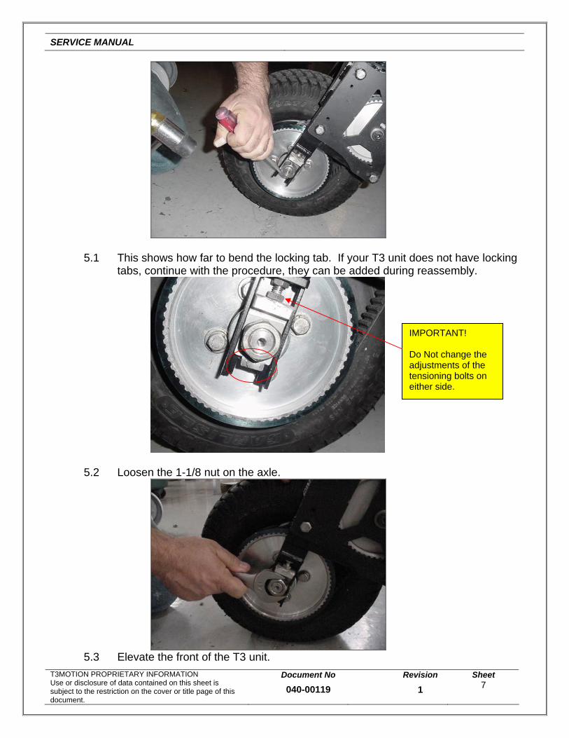
5.0 With the screwdriver and the mallet, pry down the locking tab on the left side.
SERVICE MANUAL
T3MOTION PROPRIETARY INFORMATION Use or disclosure of data contained on this sheet is subject to the restriction on the cover or title page of this document.
Document No
040-00119
Revision
1
Sheet 7
5.1 This shows how far to bend the locking tab. If your T3 unit does not have locking
tabs, continue with the procedure, they can be added during reassembly.
5.2 Loosen the 1-1/8 nut on the axle.
5.3 Elevate the front of the T3 unit.
IMPORTANT! Do Not change the adjustments of the tensioning bolts on either side.

SERVICE MANUAL
T3MOTION PROPRIETARY INFORMATION Use or disclosure of data contained on this sheet is subject to the restriction on the cover or title page of this document.
Document No
040-00119
Revision
1
Sheet 8
5.4 Remove the nut you loosened on the left side of the axle.
6.0 Slide the axle through towards the right side. You will probably need the mallet
and screwdriver.

SERVICE MANUAL
T3MOTION PROPRIETARY INFORMATION Use or disclosure of data contained on this sheet is subject to the restriction on the cover or title page of this document.
Document No
040-00119
Revision
1
Sheet 9
6.1 Note the amount and location of the shims when the axle comes out. There are two shims for the left side of the axle.
6.2 Remove the wheel assembly from the belt and fork.
7.0 Remove the 9/16 inch nylock nut on the on the shoulder bolt.

SERVICE MANUAL
T3MOTION PROPRIETARY INFORMATION Use or disclosure of data contained on this sheet is subject to the restriction on the cover or title page of this document.
Document No
040-00119
Revision
1
Sheet 10
7.1 Remove the three 9/16 bolts that hold the side plate onto the fork frame.
7.2 Remove the shoulder bolt with a ¼ inch Allen wrench. (Socket type shown.)
7.3 Remove the side plate with the shoulder bolt and secondary pulley assembly as
one unit. (The secondary belt is on the floor in this picture.)

SERVICE MANUAL
T3MOTION PROPRIETARY INFORMATION Use or disclosure of data contained on this sheet is subject to the restriction on the cover or title page of this document.
Document No
040-00119
Revision
1
Sheet 11
7.4 If you are changing the primary belt, remove and replace it at this time.
8.0 Note there is a shim between the small pulley and the inner mounting plate. It is
possible to have different sized shims and one or more on each side of the pulley/bearing assembly. Note location of shoulder bolt in side plate and the shims on the shoulder bolt. Be sure to replace them the same way they were installed originally.
Shims. There maybe more than one on each side. Only one shim shown on each side of the pulley in these pictures. Note the thickness and locations of shims while disassembling.

SERVICE MANUAL
T3MOTION PROPRIETARY INFORMATION Use or disclosure of data contained on this sheet is subject to the restriction on the cover or title page of this document.
Document No
040-00119
Revision
1
Sheet 12
8.1 This is an assembled secondary pulley and bearing set with a crush tube between the bearings. If the removed assembly did not have a crush tube when it was disassembled, install one at this time when you are installing new bearings. Bearings should be a very tight fit into the pulleys as should the fit of the smaller pulley into the larger pulley. Be sure to seat the bearings completely into the pulleys.
9.0 Slide the secondary pulley/bearing assembly onto the shoulder bolt that is
installed in the side plate with the shims that were removed earlier. Place the primary belt on the larger pulley as shown.

SERVICE MANUAL
T3MOTION PROPRIETARY INFORMATION Use or disclosure of data contained on this sheet is subject to the restriction on the cover or title page of this document.
Document No
040-00119
Revision
1
Sheet 13
9.1 Place the secondary belt on the smaller pulley and thread the shoulder bolt into the fork. (Allen wrench socket is shown in shoulder bolt.) Do Not tighten the shoulder bolt at this time.
9.2 Install the three 9/16 bolts that attach the side plate to the fork. Fully tighten
them at this time.

SERVICE MANUAL
T3MOTION PUse or disclosubject to thedocument.
9.3 Tighten the shoulder bolt using the ¼ inch Allen wrench. Be sure not to pinch any shims between the edge of the shoulder bolt and the fork. Torque to 20 ft.lbs. Install the nylock nut onto the shoulder bolt and tighten.
10.0 Sometimes the bearings shift inside the hub during transit or being moved
without an axle installed. They can be realigned easily with the axle just by sliding it in at an angle to catch the bearings. See photo in step 10.2.
10.1 Note the order of the nut, locking tab, adjustment block and spacer on the axle.
This is the right side.
This is the left side.
t
NuAdjustment Block
ROPRIETARY INFORMATION sure of data contained on this sheet is restriction on the cover or title page of th
Spacer
is
Document No
040-00119
Revision
1
Sheet 14
Locking tab
SERVICE MANUAL
T3MOTION PROPRIETARY INFORMATION Use or disclosure of data contained on this sheet is subject to the restriction on the cover or title page of this document.
Document No
040-00119
Revision
1
Sheet 15
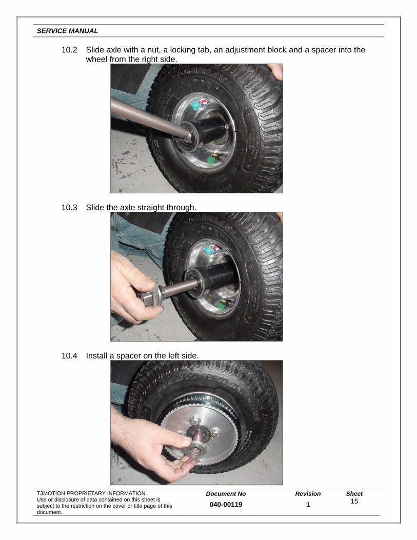
10.2 Slide axle with a nut, a locking tab, an adjustment block and a spacer into the wheel from the right side.
10.3 Slide the axle straight through.
10.4 Install a spacer on the left side.

SERVICE MANUAL
T3MOTION PROPRIETARY INFORMATION Use or disclosure of data contained on this sheet is subject to the restriction on the cover or title page of this document.
Document No
040-00119
Revision
1
Sheet 16
10.5 Guide the secondary belt around the pulley and position the wheel assembly between the forks.
11.0 Note the orientation of the adjustment block in this picture. This is the right side
and for now, install the adjustment block upside down to the way it came off.
11.1 On the left side, slide the two shims back between the fork and spacer.

SERVICE MANUAL
T3MOTION PROPRIETARY INFORMATION Use or disclosure of data contained on this sheet is subject to the restriction on the cover or title page of this document.
Document No
040-00119
Revision
1
Sheet 17
11.2 Then push the axle all the way through.
11.3 Install the left side adjustment block the same way it came off. You will probably
need to tap it into place with the mallet.
11.4 Install the locking tab and nut, but leave a space between the nut and adjustment
block as shown.

SERVICE MANUAL
T3MOTION PROPRIETARY INFORMATION Use or disclosure of data contained on this sheet is subject to the restriction on the cover or title page of this document.
Document No
040-00119
Revision
1
Sheet 18
11.5 Tap the axle back towards the right side with the mallet.
11.6 Rotate the right side adjustment block 180 degrees back to the position it was
before disassembly.
11.7 Tap the axle back through towards the left side.

SERVICE MANUAL
T3MOTION PROPRIETARY INFORMATION Use or disclosure of data contained on this sheet is subject to the restriction on the cover or title page of this document.
Document No
040-00119
Revision
1
Sheet 19
11.8 Tighten nut on left side. Make it firmly snug, but do not over tighten.
12.0 Check the tension of the belt.
12.1 With the pliers bend the locking tab up against the nut.

SERVICE MANUAL
T3MOTION PROPRIETARY INFORMATION Use or disclosure of data contained on this sheet is subject to the restriction on the cover or title page of this document.
Document No
040-00119
Revision
1
Sheet 20
13.0 Reinstall front fender. Use the same fasteners you removed to take it off. Just reverse the procedure. Do not fully tighten any of the fasteners until all of the fasteners are in place. Do not over tighten the fasteners.
For addition information, contact T3 Motion at: (714)-619-3605.


![0) · 2016. 7. 8. · x\hsp[`th`]hy`klwlukpunvu svjh[pvu ;opz^psshhlj[Äuhs lhkpunz ... pj /\tpjhjpk)sluk-sv^ly luohujly t3 t3 t3 t3 t3 t3 t3 t3 t3 t3 t3 t3 t3 t3 t3 t3 t3 t3 t3 t3](https://img.dokumen.tips/doc/110x75/60d98d4a31005a4c8d3c5fa4/0-2016-7-8-xhspthhyklwlukpunvu-svjhpvu-opzpsshhljuhs-lhkpunz-.jpg)