Embed Size (px)
Citation preview
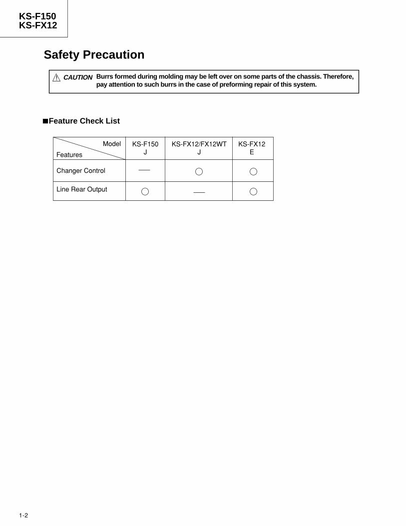
KS-F150KS-FX12
Safety precaution ------------------------------------- 1-2Instructions --------------------------------------------- 1-3 - 12Disassembly method --------------------------------- 2-1Adjustment method ----------------------------------- 2-8Description of major ICs ----------------------------- 2-12
Block diagram ----------------------------------------- 2-18Standard schematic diagrams --------------------- 2-19Printed circuit boards -------------------------------- 2-22 - 24Parts list ------------------------------------------------ 3-1 - 13
Contents
CASSETTE RECEIVER
SERVICE MANUAL
KS-FX12KS-FX12WT
KS-F150
No.49522Nov. 1999
COPYRIGHT 1999 VICTOR COMPANY OF JAPAN, LTD.
Area Suffix
[KS-F150]
J ...... Northern America
Area Suffix
[KS-FX12WT]
J ...... Northern America
Area Suffix
[KS-FX12]
J ...... Northern America
E ... Continental Europe
SYSTEM CPU
LC72362N
HEAD AMP
UPC1228HA
PLAYBACK HEAD
1-0036-7016S
1-2
KS-F150KS-FX12
! CAUTION Burrs formed during molding may be left over on some parts of the chassis. Therefore, pay attention to such burrs in the case of preforming repair of this system.
Safety Precaution
Model
Features
KS-F150J
KS-FX12/FX12WTJ
KS-FX12E
Changer Control
Line Rear Output
Feature Check List
1-3
KS-F150KS-FX12
Instructions
2
EN
GL
ISH
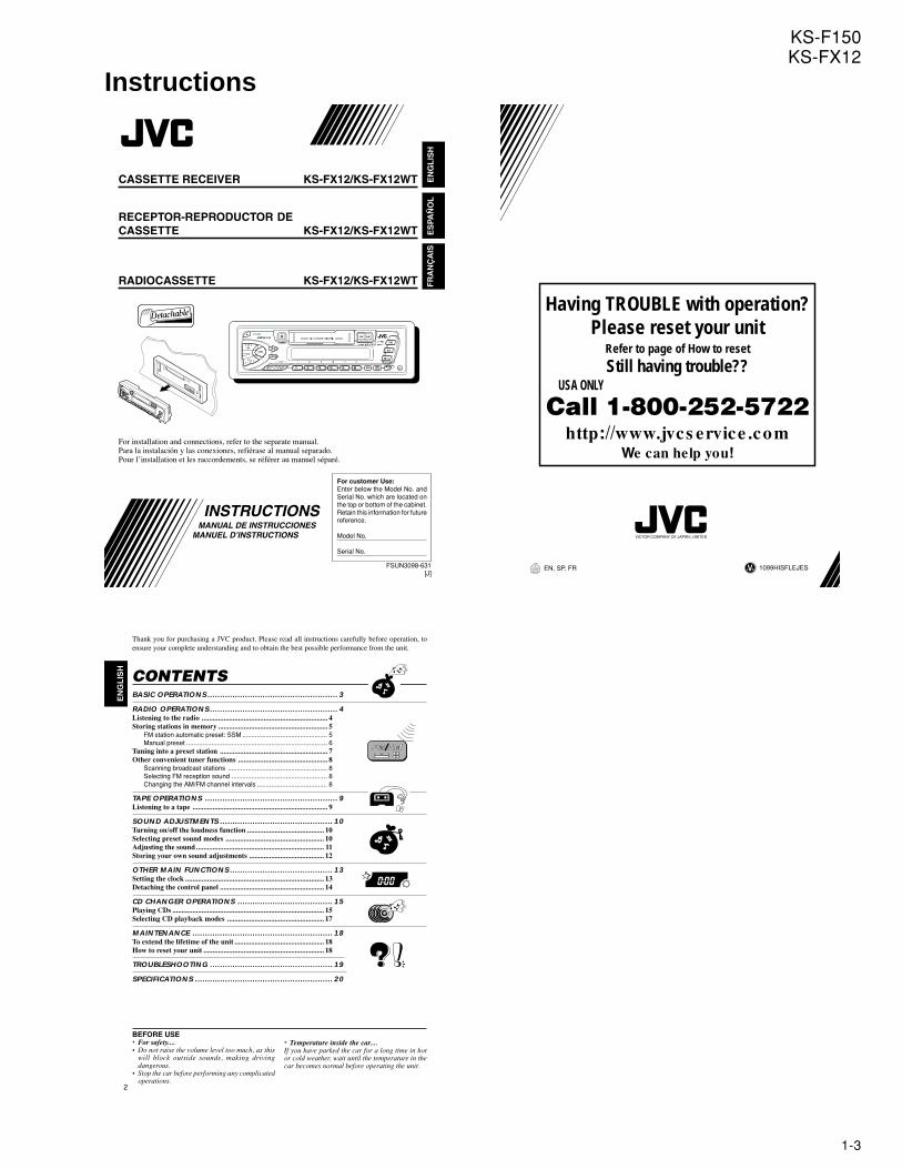
Thank you for purchasing a JVC product. Please read all instructions carefully before operation, toensure your complete understanding and to obtain the best possible performance from the unit.
CONTENTSBASIC OPERATIONS.................................................... 3
RADIO OPERATIONS................................................... 4Listening to the radio ..................................................................... 4Storing stations in memory ............................................................ 5
FM station automatic preset: SSM ............................................... 5Manual preset .............................................................................. 6
Tuning into a preset station ........................................................... 7Other convenient tuner functions ................................................. 8
Scanning broadcast stations ....................................................... 8Selecting FM reception sound ..................................................... 8Changing the AM/FM channel intervals ....................................... 8
TAPE OPERATIONS ..................................................... 9Listening to a tape .......................................................................... 9
SOUND ADJUSTMENTS ............................................. 10Turning on/off the loudness function .......................................... 10Selecting preset sound modes ...................................................... 10Adjusting the sound ...................................................................... 11Storing your own sound adjustments ......................................... 12
OTHER MAIN FUNCTIONS ......................................... 13Setting the clock ............................................................................ 13Detaching the control panel ......................................................... 14
CD CHANGER OPERATIONS ...................................... 15Playing CDs ................................................................................... 15Selecting CD playback modes ..................................................... 17
MAINTENANCE ........................................................ 18To extend the lifetime of the unit ................................................. 18How to reset your unit .................................................................. 18
TROUBLESHOOTING ................................................. 19
SPECIFICATIONS ....................................................... 20
BEFORE USE* For safety....• Do not raise the volume level too much, as this
will block outside sounds, making drivingdangerous.
• Stop the car before performing any complicatedoperations.
* Temperature inside the car....If you have parked the car for a long time in hotor cold weather, wait until the temperature in thecar becomes normal before operating the unit.
CASSETTE RECEIVER KS-FX12/KS-FX12WT EN
GL
ISH
ES
PAÑ
OL
RECEPTOR-REPRODUCTOR DECASSETTE KS-FX12/KS-FX12WT
RADIOCASSETTE KS-FX12/KS-FX12WT
INSTRUCTIONSMANUAL DE INSTRUCCIONES
MANUEL D’INSTRUCTIONS
For customer Use:Enter below the Model No. andSerial No. which are located onthe top or bottom of the cabinet.Retain this information for futurereference.
Model No.
Serial No.
FSUN3098-631[J]
For installation and connections, refer to the separate manual.Para la instalación y las conexiones, refiérase al manual separado.Pour l’installation et les raccordements, se référer au manuel séparé.
FR
AN
ÇA
IS
1099HISFLEJESJVCEN, SP, FR
VICTOR COMPANY OF JAPAN, LIMITED
Having TROUBLE with operation?Please reset your unit
Refer to page of How to reset
Still having trouble?? USA ONLY
Call 1-800-252-5722http://www.jvcs ervice .com
We can help you!
1-4
KS-F150KS-FX12
4
EN
GL
ISH
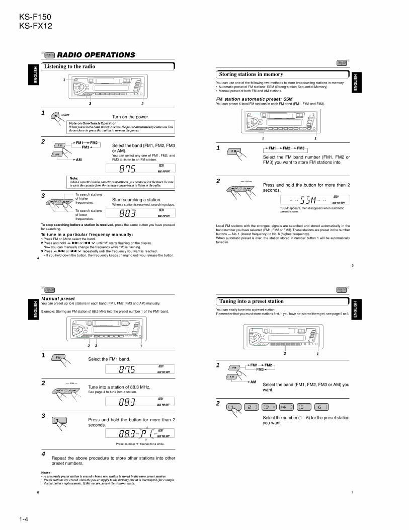
1Turn on the power.
2Select the band (FM1, FM2, FM3or AM).You can select any one of FM1, FM2, andFM3 to listen to an FM station.
3Start searching a station.When a station is received, searching stops.
To stop searching before a station is received, press the same button you have pressedfor searching.
To tune in a particular frequency manually:1 Press FM or AM to select the band.2 Press and hold T or S until “M” starts flashing on the display.
Now you can manually change the frequency while “M” is flashing.3 Press T or S repeatedly until the frequency you want is reached.
• If you hold down the button, the frequency keeps changing until you release the button.
RADIO OPERATIONSListening to the radio
To search stationsof lowerfrequencies.
To search stationsof higherfrequencies.
Note on One-Touch Operation:When you select a band in step 2 below, the power automatically comes on. Youdo not have to press this button to turn on the power.
Note:When a cassette is in the cassette compartment, you cannot select the tuner. Be sureto eject the cassette from the cassette compartment to listen to the radio.
1
23
/I/ATT
FM1 FM2FM3
A M
F M
AM
5
EN
GL
ISHStoring stations in memory
You can use one of the following two methods to store broadcasting stations in memory.• Automatic preset of FM stations: SSM (Strong-station Sequential Memory)• Manual preset of both FM and AM stations.
FM station automatic preset: SSMYou can preset 6 local FM stations in each FM band (FM1, FM2 and FM3).
1Select the FM band number (FM1, FM2 orFM3) you want to store FM stations into.
2Press and hold the button for more than 2seconds.
Local FM stations with the strongest signals are searched and stored automatically in theband number you have selected (FM1, FM2 or FM3). These stations are preset in the numberbuttons — No. 1 (lowest frequency) to No. 6 (highest frequency).When automatic preset is over, the station stored in number button 1 will be automaticallytuned in.
“SSM” appears, then disappears when automaticpreset is over.
F MFM1 FM2 FM3
12
6
EN
GL
ISH
Manual presetYou can preset up to 6 stations in each band (FM1, FM2, FM3 and AM) manually.
Example: Storing an FM station of 88.3 MHz into the preset number 1 of the FM1 band.
1Select the FM1 band.
2Tune into a station of 88.3 MHz.See page 4 to tune into a station.
3Press and hold the button for more than 2seconds.
4Repeat the above procedure to store other stations into otherpreset numbers.
Notes:• A previously preset station is erased when a new station is stored in the same preset number.• Preset stations are erased when the power supply to the memory circuit is interrupted (for example,
during battery replacement). If this occurs, preset the stations again.
Preset number “1” flashes for a while.
12 3
F M
7
EN
GL
ISH
1
Select the band (FM1, FM2, FM3 or AM) youwant.
2
Select the number (1 – 6) for the preset stationyou want.
Tuning into a preset stationYou can easily tune into a preset station.Remember that you must store stations first. If you have not stored them yet, see page 5 or 6.
2 1
FM1 FM2FM3
A M
F M
AM
1-5
KS-F150KS-FX12
8
EN
GL
ISH
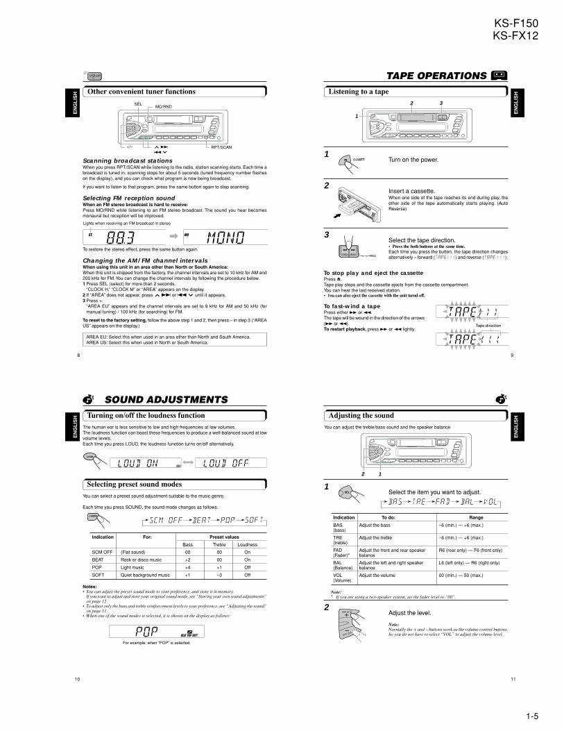
Scanning broadcast stationsWhen you press RPT/SCAN while listening to the radio, station scanning starts. Each time abroadcast is tuned in, scanning stops for about 5 seconds (tuned frequency number flasheson the display), and you can check what program is now being broadcast.
If you want to listen to that program, press the same button again to stop scanning.
Selecting FM reception soundWhen an FM stereo broadcast is hard to receive:Press MO/RND while listening to an FM stereo broadcast. The sound you hear becomesmonaural but reception will be improved.
To restore the stereo effect, press the same button again.
Changing the AM/FM channel intervalsWhen using this unit in an area other than North or South America:When this unit is shipped from the factory, the channel intervals are set to 10 kHz for AM and200 kHz for FM. You can change the channel intervals by following the procedure below.1 Press SEL (select) for more than 2 seconds.
“CLOCK H,” “CLOCK M” or “AREA” appears on the display.2 If “AREA” does not appear, press T or S until it appears.3 Press +.
“AREA EU” appears and the channel intervals are set to 9 kHz for AM and 50 kHz (formanual tuning) / 100 kHz (for searching) for FM.
To reset to the factory setting, follow the above step 1 and 2, then press – in step 3 (“AREAUS” appears on the display.)
AREA EU: Select this when used in an area other than North and South America.AREA US: Select this when used in North or South America.
Other convenient tuner functionsSEL
MO/RND
RPT/SCAN
Lights when receiving an FM broadcast in stereo
+/– TS
\
9
EN
GL
ISH
TAPE OPERATIONSListening to a tape
1Turn on the power.
2Insert a cassette.When one side of the tape reaches its end during play, theother side of the tape automatically starts playing. (AutoReverse)
3Select the tape direction.• Press the both buttons at the same time.Each time you press the button, the tape direction changesalternatively – forward ( ) and reverse ( ).
To stop play and eject the cassettePress 0.Tape play stops and the cassette ejects from the cassette compartment.You can hear the last received station.• You can also eject the cassette with the unit turnd off.
To fast-wind a tapePress either ¡ or 1.The tape will be wound in the direction of the arrows(¡ or 1).To restart playback, press ¡ or 1 lightly.
PROG
1
2 3
/I/ATT
Tape direction
10
EN
GL
ISH
SOUND ADJUSTMENTSTurning on/off the loudness function
The human ear is less sensitive to low and high frequencies at low volumes.The loudness function can boost these frequencies to produce a well-balanced sound at lowvolume levels.Each time you press LOUD, the loudness function turns on/off alternatively.
Selecting preset sound modes
You can select a preset sound adjustment suitable to the music genre.
Each time you press SOUND, the sound mode changes as follows.
Indication For: Preset values
Bass Treble Loudness
SCM OFF (Flat sound) 00 00 On
BEAT Rock or disco music +2 00 On
POP Light music +4 +1 Off
SOFT Quiet background music +1 –3 Off
Notes:• You can adjust the preset sound mode to your preference, and store it in memory.
If you want to adjust and store your original sound mode, see “Storing your own sound adjustments”on page 12.
• To adjust only the bass and treble reinforcement levels to your preference, see “Adjusting the sound”on page 11.
• When one of the sound modes is selected, it is shown on the display as follows:
For example, when “POP” is selected.
LOUD
|\
SOUND
11
EN
GL
ISHAdjusting the sound
You can adjust the treble/bass sound and the speaker balance.
1Select the item you want to adjust.
Indication To do: Range
BAS Adjust the bass –6 (min.) — +6 (max.)(bass)
TRE Adjust the treble –6 (min.) — +6 (max.)(treble)
FAD Adjust the front and rear speaker R6 (rear only) — F6 (front only)(Fader)* balance
BAL Adjust the left and right speaker L6 (left only) — R6 (right only)(Balance) balance
VOL Adjust the volume 00 (min.) — 50 (max.)(Volume)
Note:* If you are using a two-speaker system, set the fader level to “00”.
2Adjust the level.
Note:Normally the + and – buttons work as the volume control buttons.So you do not have to select “VOL” to adjust the volume level.
2 1
1-6
KS-F150KS-FX12
12
EN
GL
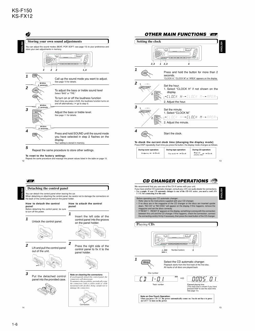
ISH Storing your own sound adjustments
You can adjust the sound modes (BEAT, POP, SOFT: see page 10) to your preference andstore your own adjustments in memory.
1Call up the sound mode you want to adjust.See page 10 for details.
2To adjust the bass or treble sound levelSelect “BAS” or “TRE.”
To turn on or off the loudness functionEach time you press LOUD, the loudness function turns onand off alternatively. (= go to step 4)
3Adjust the bass or treble level.See page 11 for details.
4Press and hold SOUND until the sound modeyou have selected in step 1 flashes on thedisplay.Your setting is stored in memory.
5Repeat the same procedure to store other settings.
To reset to the factory settingsRepeat the same procedure and reassign the preset values listed in the table on page 10.
Within5 seconds
Within5 seconds
Within5 seconds
3 2 2 1,4
SOUND
LOUD
SOUND
13
EN
GL
ISH
OTHER MAIN FUNCTIONSSetting the clock
1Press and hold the button for more than 2seconds.“CLOCK H,” “CLOCK M” or “AREA” appears on the display.
2Set the hour.1. Select “CLOCK H” if not shown on the
display.
2. Adjust the hour.
3Set the minute.1. Select “CLOCK M.”
2. Adjust the minute.
4Start the clock.
To check the current clock time (changing the display mode)Press DISP repeatedly. Each time you press the button, the display mode changes as follows.
1.
2.
2,3 1 42,3
During tuner operation: During tape operation:
ClockPlay mode ClockFrequency ClockElaps edplay ing time
During CD operation:
1.
2.
14
EN
GL
ISH
How to detach the controlpanelBefore detaching the control panel, be sureto turn off the power.
1Unlock the control panel.
2Lift and pull the control panelout of the unit.
3Put the detached controlpanel into the provided case.
How to attach the controlpanel
1Insert the left side of thecontrol panel into the grooveon the panel holder.
2Press the right side of thecontrol panel to fix it to thepanel holder.
Detaching the control panel
You can detach the control panel when leaving the car.When detaching or attaching the control panel, be careful not to damage the connectors onthe back of the control panel and on the panel holder.
Note on cleaning the connectors:If you frequently detach the control panel, theconnectors will deteriorate.To minimize this possibility, periodically wipethe connectors with a cotton swab or clothmoistened with alcohol, being careful not todamage the connectors.
Connectors
15
EN
GL
ISH
CD CHANGER OPERATIONSWe recommend that you use one of the CH-X series with your unit.If you have another CD automatic changer, consult your JVC car audio dealer for connections.• For example, if your CD automatic changer is one of the KD-MK series, you need a cord (KS-
U15K) for connecting it to this unit.
Before operating your CD automatic changer:• Refer also to the Instructions supplied with your CD changer.• If no discs are in the magazine of the CD changer or the discs are inserted upside
down, “NO CD” or “NO DISC” will appear on the display. If this happens, remove themagazine and set the discs correctly.
• If “RESET 1 - RESET 8” appears on the display, something is wrong with the connectionbetween this unit and the CD changer. If this happens, check the connection, connectthe connecting cord(s) firmly if necessary, then press the reset button of the CD changer.
Playing CDs
1Select the CD automatic changer.Playback starts from the first track of the first disc.All tracks of all discs are played back.
¢4
Number buttons
Note on One-Touch Operation:When you press CD-CH, the power automatically comes on. You do not have to press
to turn on the power.
Track number
Disc number
Elapsed playing time(The clock time is shown if you havepressed DISP to see the clock time.See page 13.)
\
1
CD-CH
1-7
KS-F150KS-FX12
16
EN
GL
ISH
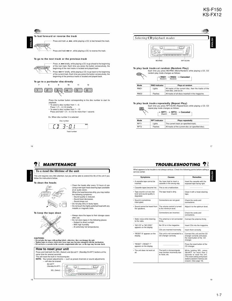
To fast forward or reverse the track
Press and hold ¢, while playing a CD, to fast forward the track.
Press and hold 4 , while playing a CD, to reverse the track.
To go to the next track or the previous track
Press ¢ briefly, while playing a CD, to go ahead to the beginningof the next track. Each time you press the button consecutively, thebeginning of the next tracks is located and played back.
Press 4 briefly, while playing a CD, to go back to the beginningof the current track. Each time you press the button consecutively, thebeginning of the previous tracks is located and played back.
To go to a particular disc directly
Press the number button corresponding to the disc number to start itsplayback.• To select a disc number from 1 – 6:
Press 1 (7) – 6 (12) briefly.• To select a disc number from 7 – 12:
Press and hold 1 (7) – 6 (12) for more than 1 second.
Ex. When disc number 3 is selected
Track number
Disc number
7 8 9 10 11 12
17
EN
GL
ISHSelecting CD playback modes
To play back tracks at random (Random Play)Each time you press MO/RND (Mono/Random) while playing a CD, CDrandom play mode changes as follows:
Mode RND Indicator Plays at random
RND1 Lights All tracks of the current disc, then the tracks of thenext disc, and so on.
RND2 Flashes All tracks of all discs inserted in the magazine.
To play back tracks repeatedly (Repeat Play)Each time you press RPT/SCAN (Repeat/Scan) while playing a CD, CDrepeat play mode changes as follows:
Mode RPT Indicator Plays repeatedly
RPT1 Lights The current track (or specified track).
RPT2 Flashes All tracks of the current disc (or specified disc).
RND1 RND2 Canceled(Random1) (Random2)
RPT1 RPT2 Canceled(Repeat1) (Repeat2)
MO/RND RPT/SCAN
MO/RND
RPTSCAN
18
EN
GL
ISH
MAINTENANCETo extend the lifetime of the unit
This unit requires very little attention, but you will be able to extend the life of the unit if youfollow the instructions below.
To clean the heads• Clean the heads after every 10 hours of use
using a wet-type head cleaning tape (availableat an audio store).When the head becomes dirty, you may realizethe following symptoms:– Sound quality is reduced.– Sound level decreases.– Sound drops out.
• Do not play dirty or dusty tapes.• Do not touch the highly-polished head with any
metallic or magnetic tools.
To keep the tape clean• Always store the tapes to their storage cases
after use.• Do not store tapes in the following places:
– Subject to direct sunlight– With high humidity– At extremely hot temperatures
CAUTIONS:• Do not play the tapes with peeling labels; otherwise, they can damage the unit.• Tighten tapes to remove slack since loose tape may become entangled with the mechanism.• Do not leave a cassette in the cassette compartment after use, as the tape may become slack.
How to reset your unitPress and hold both the SEL (Select) and (Standby/On/ATT) buttons at thesame time for several seconds.This will reset the built-in microcomputer.NOTE: Your preset adjustments — such as preset channels or sound adjustments
— will also be erased.
SEL (Select)
(Standby/On/ATT)
19
EN
GL
ISH
TROUBLESHOOTINGWhat appears to be trouble is not always serious. Check the following points before calling aservice center.
Symptoms
• A cassette tape cannot beinserted.
• Cassette tapes become hot.
• Tape sound is at very lowlevel and sound quality isdegraded.
• Sound is sometimesinterrupted.
• Sound cannot be heard fromthe speakers.
• Static noise while listeningto the radio.
• “NO CD” or “NO DISC”appears on the display.
• “RESET 8” appears on thedisplay.
• “RESET 1-RESET 7”appears on the display.
• The unit does not work atall.
Causes
You have tried to insert acassette in the wrong way.
This is not a malfunction.
The tape head is dirty.
Connections are not good.
The volume control is turnedto the minimum level.
Connections are incorrect.
The antenna is not connectedfirmly.
No CD is in the magazine.
CDs are inserted incorrectly.
This unit is not connected to aCD changer correctly.
The built-in microcomputermay function incorrectly dueto noise, etc.
Remedies
Insert the cassette with theexposed tape facing right.
Clean it with a head cleaningtape.
Check the cords andconnections.
Adjust it to the optimum level.
Check the cords andconnections.
Connect the antenna firmly.
Insert CDs into the magazine.
Insert them correctly.
Connect this unit and the CDchanger correctly and pressthe reset button of the CDchanger.
Press the reset button of theCD changer.
While holding SEL, press for more than 2
seconds to reset the unit.(The clock setting and presetstations stored in memory areerased.) (See page 18).
1-8
KS-F150KS-FX12
20
EN
GL
ISH
AUDIO AMPLIFIER SECTIONMaximum Power Output:
Front: 40 watts per channelRear: 40 watts per channel
Continuous Power Output (RMS):Front: 16 watts per channel into 4 Ω, 40
to 20,000 Hz at no more than 0.8%total harmonic distortion.
Rear: 16 watts per channel into 4 Ω, 40to 20,000 Hz at no more than 0.8%total harmonic distortion.
Load Impedance: 4 Ω (4 to 8 Ω allowance)Tone Control Range
Bass: ±10 dB at 100 HzTreble:±10 dB at 10 kHz
Frequency Response: 40 to 20,000 HzSignal-to-Noise Ratio: 70 dB
TUNER SECTIONFrequency RangeFM: 87.5 to 107.9 MHz
(with channel interval set to 200 kHz)87.5 to 108.0 MHz
(with channel interval set to 50 kHz)AM: 530 to 1,710 kHz
(with channel interval set to 10 kHz)531 to 1,602 kHz
(with channel interval set to 9 kHz)
[FM Tuner]Usable Sensitivity: 11.3 dBf (1.0 µV/75 Ω)50 dB Quieting Sensitivity:
16.3 dBf (1.8 µV/75 Ω)Alternate Channel Selectivity (400 kHz):
65 dBFrequency Response: 40 to 15,000 HzStereo Separation: 35 dBCapture Ratio: 2.0 dB
[AM Tuner]Sensitivity: 20 µVSelectivity: 35 dB
CASSETTE DECK SECTIONWow & Flutter: 0.15% (WRMS)Fast-Wind Time: 190 sec. (C-60)Frequency Response:
50 to 14,000 Hz (±3 dB)Signal-to-Noise Ratio: 52 dBStereo Separation: 40 dB
GENERALPower RequirementOperating Voltage: DC 14.4 volts (11 to 16
volts allowance)Grounding System: Negative groundDimensions (W x H x D)Installation Size:
182 x 52 x 150 mm(7-3/16" x 2-1/16" x 5-15/16")
Panel Size: 188 x 58 x 14 mm(7-7/16" x 2-5/16" x 5/8")
Mass: 1.3 kg (2.9 lbs) (excluding accessories)
Design and specifications subject to changewithout notice.
If a kit is necessary for your car, consultyour telephone directory for the nearestcar audio speciality shop.
SPECIFICATIONS
1-9
KS-F150KS-FX12
10
184 mm
53 mm
MultiMus icScan
KS-FX12KS-FX12WTInstallation/Connection ManualManual de instalación/conexiónManuel d’installation/raccordement
ESPAÑOL
• Esta unidad está diseñada para funcionar con 12 voltios deCC, con sistemas eléctricos de masa NEGATIVA.
INSTALACION (MONTAJE EN ELTABLERO DE INSTRUMENTOS)• La siguiente ilustración muestra una instalación típica. Sin
embargo usted deberá efectuar los ajustes correspondientesa su automóvil. Si tiene alguna pregunta o necesita informaciónacerca de las herramientas para instalación, consulte con suconcesionario de JVC de equipos de audio para automóviles oa una compañía que suministra tales herramientas.
FRANÇAIS
• Cet appareil est conçu pour fonctionner sur des sources decourant continu de 12 volts à masse NEGATIVE.
INSTALLATION (MONTAGE DANS LETABLEAU DE BORD)• L’illustration suivante est un exemple d’installation typique.
Cependant, vous devez faire les ajustements correspondant àvotre voiture particulière. Si vous avez des questions ou avezbesoin d’information sur des kits d’installation, consulter votrerevendeur d’autoradios JVC ou une compagnied’approvisionnement.
ENGLISH
• This unit is designed to operate on 12 volts DC, NEGATIVEground electrical systems.
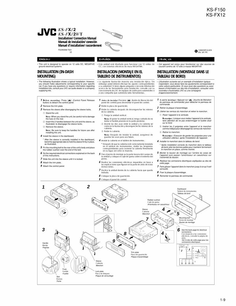
INSTALLATION (IN-DASHMOUNTING)• The following illustration shows a typical installation. However,
you should make adjustments corresponding to your specificcar. If you have any questions or require information regardinginstallation kits, consult your JVC car audio dealer or a companysupplying kits.
1 Antes de ins talar: Presione (botón de liberación delpanel de control) para desmontar el panel de control.
2 Retire la placa de guarnición.
3 Retire la cubierta después de desenganchar los retenesde la cubierta.
1 Ponga la unidad vertical.
Nota: Al poner la unidad vertical, tenga cuidado de nodañar el fusible provisto en la parte posterior.
2 Inserte las dos asas entre la unidad y la cubierta talcomo en la ilustración y desenganche los retenes de lacubierta.
3 Retire la cubierta.
Nota: Después de instalar la unidad, asegúrese deguardar las asas para uso futuro.
4 Instale la cubierta en el tablero de instrumentos.
* Después de que la cubierta esté correctamente instaladaen el tablero de instrumentos, doble las lengüetascorrespondientes para sostener la cubierta firmementeen su lugar, tal como se muestra.
5 Fixe el perno de montaje ou la parte trasera del cuerpo dela unidad y coloque el cojín de goma sobre el extremo delperno.
6 Realice las conexiones eléctricas requeridas en base alas explicaciones que figuran en la parte de atrás de estasinstrucciones.
7 Deslice la unidad dentro de la cubierta hasta que quedetrabada.
8 Coloque la placa de guarnición.
9 Coloque el panel de control.
1 Avant le montage: Appuyer sur (touche de libérationdu panneau de commande) pour détacher le panneau decommande.
2 Retirer la plaque d’assemblage.
3 Libérer les verrous du manchon et retirer le manchon.
1 Poser l’appareil à la verticale.
Remarque: Lorsque vous mettez l’appareil à la verticale,faire attention de ne pas endommager le fusible situésur le fond.
2 Insérer les 2 poignées entre l’appareil et le manchoncomme indiqué pour désengagé les verrous de manchon.
3 Retirer le manchon.
Remarque: S'assurer de garder les poignées pour uneutilisation ultérieur, après l'installation de l'appareil.
4 Installer le manchon dans le tableau de bord.
* Après installation correcte du manchon dans le tableaude bord, plier les bonnes pattes pour maintenir fermementle manchon en place, comme montré.
5 Monter le boulon de montage sur l’arrière du corps del’appareil puis passer l’amortisseur en caoutchouc surl’extrémité du boulon.
6 Réalisez les connexions électriques expliquées au dos decette page.
7 Faire glisser l’appareil dans le manchon jusqu’à ce qu’il soitverrouillé.
8 Fixer la plaque d’assemblage.
9 Remonter le panneau de commande.
1 Before mounting : Press (Control Panel Releasebutton) to detach the control panel.
2 Remove the trim plate.
3 Remove the sleeve after disengaging the sleeve locks.
1 Stand the unit.
Note: When you stand the unit, be careful not to damagethe fuse on the rear.
2 Insert the 2 handles between the unit and the sleeve, asillustrated, to disengage the sleeve locks.
3 Remove the sleeve.
Note: Be sure to keep the handles for future use afterinstalling the unit.
4 Install the sleeve in the dashboard.
* After the sleeve is correctly installed in the dashboard,bend the appropriate tabs to hold the sleeve firmly in place,as illustrated.
5 Fix the mounting bolt to the rear of the unit’s body and placethe rubber cushion over the end of the bolt.
6 Do the required electrical connections explained on the backof this instructions.
7 Slide the unit into the sleeve until it is locked.
8 Attach the trim plate.
9 Attach the control panel.
JVC
FSUN3098-T631[J]
1099HISFLEJESEN, SP, FR
Rubber cushionCojín de gomaAmortisseur en caoutchouc
7
Trim platePlaca de guarniciónPlaque d’assemblage
*3
Mounting boltPerno de montajeBoulon de montage
DashboardTablero de instrumentosTableau de bord
See the back page for electricalconnections.Con respecto a las conexioneseléctricas, consulte la página deatrás.Voir le dos de cette page pour lesconnexions électriques.
SleeveCubiertaManchon
46
54
1 2
FuseFusibleFusible
89
MultiMus icScan
10
12 3
1
2
3
5
4
SlotRanuraFente
HandleManijaPoignée
Lock platePlaca de bloqueoPlaque de verrouillage
SleeveCubiertaManchon
1-10
KS-F150KS-FX12
Liste des pièces pour l’installation etraccordementLes pièces suivantes sont fournies avec cet appareil.Après vérification, veuillez les placer correctement.
Lista de piezas para instalación y conexiónCon esta unidad se suministran las siguientes piezas.Después de inspeccionarlas, colóquelas correctamente.
3
HandleManijaPoignée
21
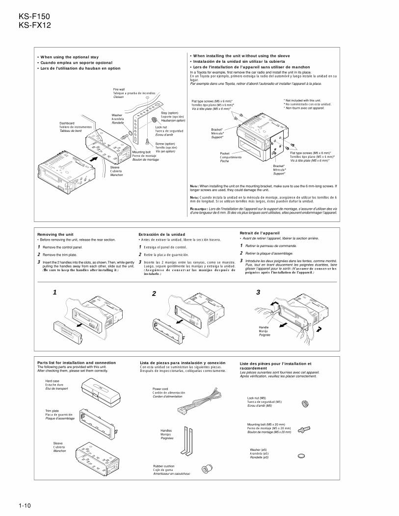
Removing the unit• Before removing the unit, release the rear section.
1 Remove the control panel.
2 Remove the trim plate.
3 Insert the 2 handles into the slots, as shown. Then, while gentlypulling the handles away from each other, slide out the unit.(Be s ure to keep the handles after ins talling it.)
Extracción de la unidad• Antes de extraer la unidad, libere la sección trasera.
1 Extraiga el panel de control.
2 Retire la placa de guarnición.
3 Inserte las 2 manijas entre las ranuras, como se muestra.Luego, separe gentilmente las manijas y extraiga la unidad.(As e g úre s e de c o ns e rv ar las manijas de s pués de
ins talarlo .)
Note: When installing the unit on the mounting bracket, make sure to use the 6 mm-long screws. Iflonger screws are used, they could damage the unit.
Nota: Cuando instala la unidad en la ménsula de montaje, asegúrese de utilizar los tornillos de 6mm de longitud. Si se utilizan tornillos más largos, éstos pueden dañar la unidad.
Remarque: Lors de l'installation de l’appareil sur le support de montage, s’assurer d’utiliser des visd’une longueur de 6 mm. Si des vis plus longues sont utilisées, elles peuvent endommager l’appareil.
•When installing the unit without using the sleeve• Instalación de la unidad sin utilizar la cubierta•Lors de l'installation de l’appareil sans utiliser de manchonIn a Toyota for example, first remove the car radio and install the unit in its place.En un Toyota por ejemplo, primero extraiga la radio del automóvil y luego instale la unidad en sulugar.Par exemple dans une Toyota, retirer d’abord l’autoradio et installer l’appareil à la place.
•When using the optional stay•Cuando emplea un soporte opcional• Lors de l'utilisation du hauban en option
DashboardTablero de instrumentosTableau de bord
Fire wallTabique a prueba de incendiosCloison
WasherArandelaRondelle
Mounting boltPerno de montajeBoulon de montage
SleeveCubiertaManchon
Screw (option)Tornillo (opción)Vis (en option)
Bracket*Ménsula*Support*
PocketCompartimientoPoche
Bracket*Ménsula*Support*
Flat type screws (M5 x 6 mm)*Tornillos tipo plano (M5 x 6 mm)*Vis à tête plate (M5 x 6 mm)*
Flat type screws (M5 x 6 mm)*Tornillos tipo plano (M5 x 6 mm)*Vis à tête plate (M5 x 6 mm)*
* Not included with this unit.* No suministrado con esta unidad.* Non fourni avec cet appareil.
Retrait de l’appareil• Avant de retirer l’appareil, libérer la section arrière.
1 Retirer le panneau de commande.
2 Retirer la plaque d’assemblage.
3 Introduire les deux poignées dans les fentes, comme montré.Puis, tout en tirant doucement les poignées écartées, faireglisser l’appareil pour le sortir. (S 'as s urer de cons erver les
poignées après l’ins tallation de l’appare il.)
Parts list for installation and connectionThe following parts are provided with this unit.After checking them, please set them correctly.
Stay (option)Soporte (opción)Hauban(en option)
Lock nutTuerca de seguridadEcrou d’arrêt
HandlesManijasPoignées
Lock nut (M5)Tuerca de seguridad (M5)Ecrou d’arrêt (M5)
Mounting bolt (M5 x 20 mm)Perno de montaje (M5 x 20 mm)Boulon de montage (M5 x 20 mm)
Power cordCordón de alimentaciónCordon d’alimentation
Rubber cushionCojín de gomaAmortisseur en caoutchouc
Washer (ø5)Arandela (ø5)Rondelle (ø5)
Trim platePlaca de guarniciónPlaque d’assemblage
Hard caseEstuche duroEtui de transport
SleeveCubiertaManchon
MultiMus icScan
MultiMus icScan
1-11
KS-F150KS-FX12
10
2
1
3
3
5
4
2
1
ENGLISH
ELECTRICAL CONNECTIONSTo prevent short circuits, we recommend that you disconnect thebattery’s negative terminal and make all electrical connectionsbefore installing the unit. If you are not sure how to install this unitcorrectly, have it installed by a qualified technician.
Note:This unit is designed to operate on 12 vo lts DC, NEGATIVEground e lectrical s ys tems . If your vehicle does not have thissystem, a voltage inverter is required, which can be purchased atJVC car audio dealers.• Replace the fuse with one of the specified rating. If the fuse
blows frequently, consult your JVC car audio dealer.• If noise is a problem...
This unit incorporates a noise filter in the power circuit. However,with some vehicles, clicking or other unwanted noise may occur.If this happens, connect the unit’s rear ground terminal (Seeconnection diagram below.) to the car’s chassis using shorterand thicker cords, such as copper braiding or gauge wire. If noisestill persists, consult your JVC car audio dealer.
• Maximum input of the speakers should be more than 40 watts atthe rear and 40 watts at the front, with an impedance of 4 to 8ohms .
• Be s ure to ground this unit to the car’s chas s is .• The heat sink becomes very hot after use. Be careful not to
touch it when removing this unit.
ESPAÑOL
CONEXIONES ELECTRICASPara evitar cortocircuitos, recomendamos que desconecte elterminal negativo de la batería y que efectúe todas las conexioneseléctricas antes de instalar la unidad. Si usted no está seguro decómo instalar correctamente la unidad, hágala instalar por untécnico cualificado.
Nota:Esta unidad está diseñada para funcionar con 12 vo ltios de CC,con s is temas e léctricos de mas a NEGATIVA. Si su vehículo noposee este sistema, será necesario un inversor de tensión, quepuede ser adquirido en los concesionarios de JVC de equiposde audio para automóviles.• Reemplace el fusible por uno con la corriente especificada. Si
el fusible se quemase frecuentemente consulte con suconcesionario de JVC de equipos de audio para automóviles.
• Si el ruido fuese un problema...Esta unidad tiene un filtro de ruido en el circuito de alimentación.Sin embargo, en algunos vehículos, pueden producirsechasquidos u otros ruidos indeseados. En tal caso conecte elterminal de tierra pos terior (Ver diagrama de conexión abajo.)del receptor al chasis del automóvil, utilizando cordones másgruesos y cortos tales como alambre de cobre trenzado o degrueso calibre. Si el ruido persiste, consulte a su concesionariode JVC de equipos de audio para automóvil.
• La entrada máxima de los altavoces traseros debe ser mayorde 40 vatios y la de los delanteros de 40 vatios, con unaimpedancia de 4 a 8 ohmnios .
• As egúres e de conectar es ta unidad a tierra en e l chas is de lautomóvil.
• El sumidero térmico estará muy caliente después del uso.Asegúrese de no tocarlo al desmontar esta unidad.
FRANÇAIS
RACCORDEMENTS ELECTRIQUESPour éviter tout court-circuit, nous vous recommandons dedébrancher la borne négative de la batterie et d’effectuer tous lesraccordements électriques avant d’installer l’appareil. Si l'on n’estpas sûr de pouvoir installer correctement cet appareil, le faireinstaller par un technicien qualifié.
Remarque:Cet appareil est conçu pour fonctionner sur des sources de courantcontinu de 12 vo lts à mas s e NEGATIVE. Si votre véhicule n’offrepas ce type d’alimentation, il vous faut un convertisseur de tension,que vous pouvez acheter chez un revendeur d’autoradios JVC.• Remplacer le fusible par un de la valeur précisée. Si le fusible
saute souvent, consulter votre revendeur d’autoradios JVC.• Si le bruit est un problème...
Cet appareil incorpore un filtre de bruit dans le circuitd’alimentation. Cependant, avec certains véhicules, quelquesclaquements ou autres bruits non désirés risquent de se produire.Si cela arrive, raccorder la borne de mas s e arrière de l’appareilau châssis de la voiture (voir le schéma de raccordement ci-dessous) en utilisant des cordons les plus gros et les plus courtspossibles telle qu'une barre de cuivre ou une tresse. Si le bruitpersiste, consulter votre revendeur d’autoradios JVC.
• La puissance admissible des haut-parleurs doit être supérieureà 40 watts à l’arrière et à 40 watts l’avant, avec une impédancede 4 à 8 ohms .
• S 'as s urer de raccorder la mis e à la mas s e de cet appare ilau châs s is de la vo iture .
• Le radiateur devient très chaud après usage. Faire attention dene pas le toucher en retirant cet appareil.
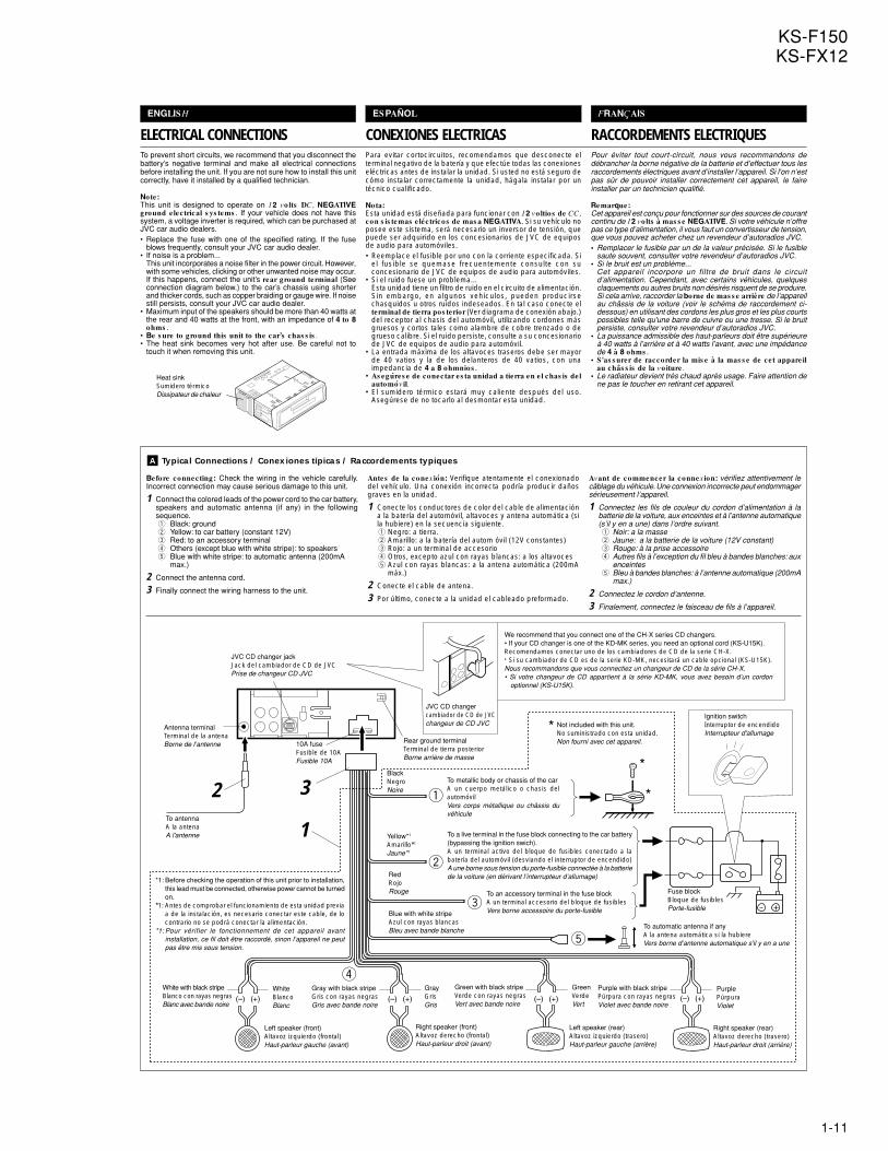
A Typical Connections / Conexiones típicas / Raccordements typiques
Before connecting: Check the wiring in the vehicle carefully.Incorrect connection may cause serious damage to this unit.
1 Connect the colored leads of the power cord to the car battery,speakers and automatic antenna (if any) in the followingsequence.1 Black: ground2 Yellow: to car battery (constant 12V)3 Red: to an accessory terminal4 Others (except blue with white stripe): to speakers5 Blue with white stripe: to automatic antenna (200mA
max.)
2 Connect the antenna cord.
3 Finally connect the wiring harness to the unit.
Antes de la conex ión: Verifique atentamente el conexionadodel vehículo. Una conexión incorrecta podría producir dañosgraves en la unidad.
1 Conecte los conductores de color del cable de alimentacióna la batería del automóvil, altavoces y antena automática (sila hubiere) en la secuencia siguiente.1 Negro: a tierra.2 Amarillo: a la batería del autom óvil (12V constantes)3 Rojo: a un terminal de accesorio4 Otros, excepto azul con rayas blancas: a los altavoces5 Azul con rayas blancas: a la antena automática (200mA
máx.)
2 Conecte el cable de antena.
3 Por último, conecte a la unidad el cableado preformado.
Avant de commencer la connex ion: vérifiez attentivement lecâblage du véhicule. Une connexion incorrecte peut endommagersérieusement l’appareil.
1 Connectez les fils de couleur du cordon d’alimentation à labatterie de la voiture, aux enceintes et à l’antenne automatique(s’il y en a une) dans l’ordre suivant.1 Noir: a la masse2 Jaune: a la batterie de la voiture (12V constant)3 Rouge: à la prise accessoire4 Autres fils à l’exception du fil bleu à bandes blanches: aux
enceintes5 Bleu à bandes blanches: à l’antenne automatique (200mA
max.)
2 Connectez le cordon d’antenne.
3 Finalement, connectez le faisceau de fils à l’appareil.
Heat sinkSumidero térmicoDissipateur de chaleur
WhiteBlancoBlanc
GrayGrisGris
GreenVerdeVert
PurplePúrpuraViolet
*1: Before checking the operation of this unit prior to installation,this lead must be connected, otherwise power cannot be turnedon.
*1: Antes de comprobar el funcionamiento de esta unidad previaa de la instalación, es necesario conectar este cable, de locontrario no se podrá conectar la alimentación.
*1: Pour vérifier le fonctionnement de cet appareil avantinstallation, ce fil doit être raccordé, sinon l’appareil ne peutpas être mis sous tension.
To antennaA la antenaA l'antenne
Left speaker (front)Altavoz izquierdo (frontal)Haut-parleur gauche (avant)
Right speaker (front)Altavoz derecho (frontal)Haut-parleur droit (avant)
Left speaker (rear)Altavoz izquierdo (trasero)Haut-parleur gauche (arrière)
Right speaker (rear)Altavoz derecho (trasero)Haut-parleur droit (arrière)
BlackNegroNoire
10A fuseFusible de 10AFusible 10A
Antenna terminalTerminal de la antenaBorne de l’antenne
Fuse blockBloque de fusiblesPorte-fusible
To metallic body or chassis of the carA un cuerpo metálico o chasis delautomóvilVers corps métallique ou châssis duvéhicule
*
*
Ignition switchInterruptor de encendidoInterrupteur d'allumage
Not included with this unit.No suministrado con esta unidad.Non fourni avec cet appareil.
*
To a live terminal in the fuse block connecting to the car battery(bypassing the ignition swich).A un terminal activo del bloque de fusibles conectado a labatería del automóvil (desviando el interruptor de encendido)A une borne sous tension du porte-fusible connectée à la batteriede la voiture (en dérivant l’interrupteur d’allumage)
Yellow*1
Amarillo*1
Jaune*1
RedRojoRouge
Blue with white stripeAzul con rayas blancasBleu avec bande blanche
To automatic antenna if anyA la antena automática si la hubiereVers borne d’antenne automatique s'il y en a une
To an accessory terminal in the fuse blockA un terminal accesorio del bloque de fusiblesVers borne accessoire du porte-fusible
Rear ground terminalTerminal de tierra posteriorBorne arrière de masse
White with black stripeBlanco con rayas negrasBlanc avec bande noire
Gray with black stripeGris con rayas negrasGris avec bande noire
Green with black stripeVerde con rayas negrasVert avec bande noire
Purple with black stripePúrpura con rayas negrasViolet avec bande noire
JVC CD changer jackJack del cambiador de CD de JVCPrise de changeur CD JVC
We recommend that you connect one of the CH-X series CD changers.• If your CD changer is one of the KD-MK series, you need an optional cord (KS-U15K).Recomendamos conectar uno de los cambiadores de CD de la serie CH-X.• Si su cambiador de CD es de la serie KD-MK, necesitará un cable opcional (KS-U15K).Nous recommandons que vous connectiez un changeur de CD de la série CH-X.• Si votre changeur de CD appartient à la série KD-MK, vous avez besoin d’un cordon
optionnel (KS-U15K).
JVC CD changercambiador de CD de JVCchangeur de CD JVC
1-12
KS-F150KS-FX12
LOCALIZACION DE AVERIAS• El fus ible s e quema.
* ¿Están los conductores rojo y negro correctamente conectados?
• No es pos ible conectar la alimentac ión.
* ¿Está el cable amarillo conectado?
• No s ale s onido de los altavoces .
* ¿Está el cable de salida del altavoz cortocircuitado?
• El s onido pres enta dis tors ión.
* ¿Está el cable de salida del altavoz conectado a masa?* ¿Están los terminales “–” de los altavoces L y R conectados a
una masa común?
• La unidad s e calienta.
* ¿Está el cable de salida del altavoz conectado a masa?* ¿Están los terminales “–” de los altavoces L y R conectados a
una masa común?
EN CAS DE DIFFICULTÉS• Le fus ible s aute .
* Les fils rouge et noir sont-ils racordés correctement?
• L’appare il ne peut pas être mis e s ous tens ion.
* Le fil jaune est-elle raccordée?
• Pas de s on des haut-parleurs .
* Le fil de sortie de haut-parleur est-il court-circuité?
• Le s on es t déformé.
* Le fil de sortie de haut-parleur est-il à la masse?* Les bornes “–” des haut-parleurs gauche et droit sont-elles mises
ensemble à la masse?
• L’appare il dev ient chaud.
* Le fil de sortie de haut-parleur est-il à la masse?* Les bornes “–” des haut-parleurs gauche et droit sont-elles mises
ensemble à la masse?
TROUBLESHOOTING• The fus e blows .
* Are the red and black leads connected correctly?
• Power cannot be turned on.
* Is the yellow lead connected?
• No s ound from the s peakers .
* Is the speaker output lead short-circuited?
• Sound is dis torted.
* Is the speaker output lead grounded?* Are the “–” terminals of L and R speakers grounded in common?
• Unit becomes hot.
* Is the speaker output lead grounded?* Are the “–” terminals of L and R speakers grounded in common?
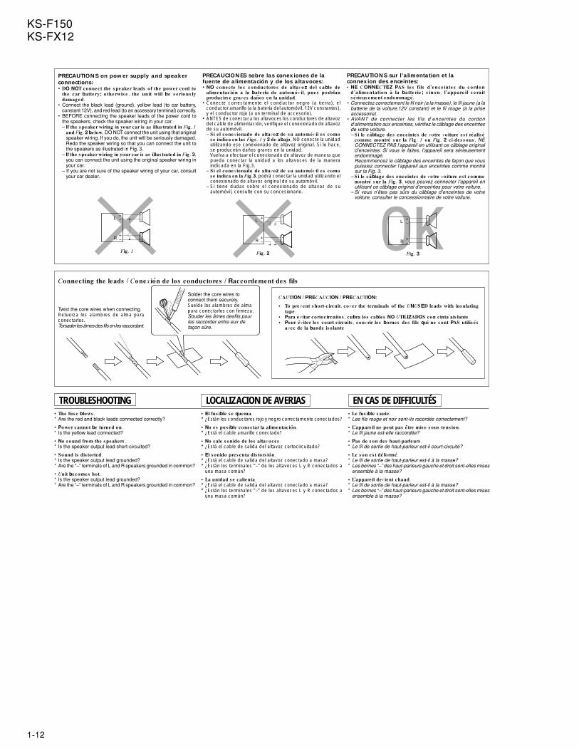
PRECAUTIONS on power supply and speakerconnections:• DO NOT connect the s peaker leads of the power cord to
the c ar batte ry; o the rwis e , the unit will be s e rio us ly
damaged.
• Connect the black lead (ground), yellow lead (to car battery,constant 12V), and red lead (to an accessory terminal) correctly.
• BEFORE connecting the speaker leads of the power cord tothe speakers, check the speaker wiring in your car.– If the s peaker wiring in your car is as illus trated in Fig . 1
and Fig. 2 below, DO NOT connect the unit using that originalspeaker wiring. If you do, the unit will be seriously damaged.Redo the speaker wiring so that you can connect the unit tothe speakers as illustrated in Fig. 3.
– If the s peaker wiring in your car is as illus trated in Fig . 3,
you can connect the unit using the original speaker wiring inyour car.
– If you are not sure of the speaker wiring of your car, consultyour car dealer.
PRECAUCIONES sobre las conexiones de lafuente de alimentación y de los altavoces:• NO c o ne c te lo s c o nduc to re s de altavo z de l c able de
alime ntac ión a la bate ría de auto móv il, pue s po dríanproducirs e graves daños en la unidad.
• Conecte correctamente el conductor negro (a tierra), elconductor amarillo (a la batería del automóvil, 12V constantes),y el conductor rojo (a un terminal de accesorio).
• ANTES de conectar a los altavoces los conductores de altavozdel cable de alimentación, verifique el conexionado de altavozde su automóvil.– Si e l conex ionado de altavoz de s u automóvil es como
s e indica en las Figs . 1 y 2 de abajo , NO conecte la unidadutilizando ese conexionado de altavoz original. Si lo hace,se producirán daños graves en la unidad.Vuelva a efectuar el conexionado de altavoz de manera quepueda conectar la unidad a los altavoces de la maneraindicada en la Fig.3.
– Si e l conex ionado de altavoz de s u automóvil es comos e indica en la Fig .3, podrá conectar la unidad utilizando elconexionado de altavoz original de su automóvil.
– Si tiene dudas sobre el conexionado de altavoz de suautomóvil, consulte con su concesionario.
Connecting the leads / Conex ión de los conductores / Raccordement des fils
CAUTION / PRECAUCION / PRECAUTION:
• To prevent s hort-c ircuit, cover the terminals of the UNUSED leads with ins ulating
tape .
• Para ev itar cortoc ircuitos , cubra los cables NO UTILIZADOS con c inta ais lante .
• Pour év iter les court-c ircuits , couvrir les bornes des fils qui ne s ont PAS utilis és
avec de la bande is o lante
Solder the core wires toconnect them securely.Suelde los alambres de almapara conectarlos con firmeza.Souder les âmes desfils pourles raccorder entre eux defaçon sûre.
Twist the core wires when connecting.Retuerza los alambres de alma paraconectarlos.Torsader les âmes des fils en les raccordant.
Fig . 1
L
R+-
+-
+
-
+
-
Fig . 2
L
R+-
+-
+
-
+
-
L
R+-
+-
+
-
+
-
Fig . 3
PRECAUTIONS sur l’alimentation et laconnexion des enceintes:• NE CONNECTEZ PAS le s fils d’e nc e inte s du c o rdo n
d’alime ntatio n à la batte rie ; s ino n, l’appare il s e raits érieus ement endommagé.
• Connectez correctement le fil noir (a la masse), le fil jaune (a labatterie de la voiture,12V constant) et le fil rouge (à la priseaccessoire).
• AVANT de connecter les fils d ’enceintes du cordond’alimentation aux enceintes, vérifiez le câblage des enceintesde votre voiture.– Si le câblage des ence intes de votre vo iture es t réalis é
comme montré s ur la Fig . 1 ou Fig . 2 c i-des s ous , NECONNECTEZ PAS l’appareil en utilisant ce câblage originald’enceintes. Si vous le faites, l’appareil sera sérieusementendommagé.Recommencez le câblage des enceintes de façon que vouspuissiez connecter l’appareil aux enceintes comme montrésur la Fig. 3.
– Si le câblage des ence intes de votre vo iture es t commemontré s ur la Fig . 3, vous pouvez connecter l’appareil enutilisant ce câblage original d’enceintes pour votre voiture.
– Si vous n’êtes pas sûrs du câblage d’enceintes de votrevoiture, consulter le concessionnaire de votre voiture.
2-1
KS-F150KS-FX12
Fig. 3
dFront chassis
a ee
a
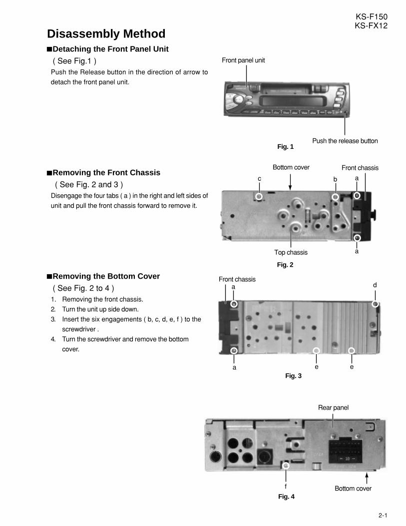
Disassembly MethodDetaching the Front Panel Unit
( See Fig.1 )Push the Release button in the direction of arrow to
detach the front panel unit.
Removing the Front Chassis
( See Fig. 2 and 3 )Disengage the four tabs ( a ) in the right and left sides of
unit and pull the front chassis forward to remove it.
Removing the Bottom Cover
( See Fig. 2 to 4 )1. Removing the front chassis.
2. Turn the unit up side down.
3. Insert the six engagements ( b, c, d, e, f ) to the
screwdriver .
4. Turn the screwdriver and remove the bottom
cover.
Fig. 1Push the release button
Front panel unit
a
a
Fig. 2
Top chassis
Front chassisBottom cover
bc
Fig. 4
f Bottom cover
Rear panel
2-2
KS-F150KS-FX12
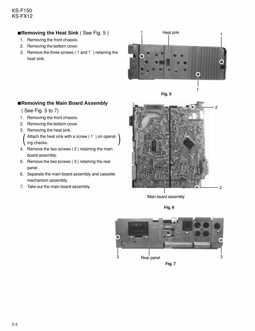
Removing the Heat Sink ( See Fig. 5 )1. Removing the front chassis.
2. Removing the bottom cover.
3. Remove the three screws ( 1 and 1` ) retaining the
heat sink.
Removing the Main Board Assembly
( See Fig. 5 to 7)1. Removing the front chassis.
2. Removing the bottom cover.
3. Removing the heat sink.
Attach the heat sink with a screw ( 1` ) on operat-
ing checks.
4. Remove the two screws ( 2 ) retaining the main
board assembly.
5. Remove the two screws ( 3 ) retaining the rear
panel .
6. Separate the main board assembly and cassette
mechanism assembly.
7. Take out the main board assembly.
Heat sink
Fig. 5
1 1
1`
Main board assembly
Fig. 6
2
2
Rear panelFig. 7
33
( )
2-3
KS-F150KS-FX12
Front cover
Front panel
Opration switch board
Fig. 9
Fig. 11
Fig. 10
Front cover
i ii
5 5
5 5
g
h h
h
g gA
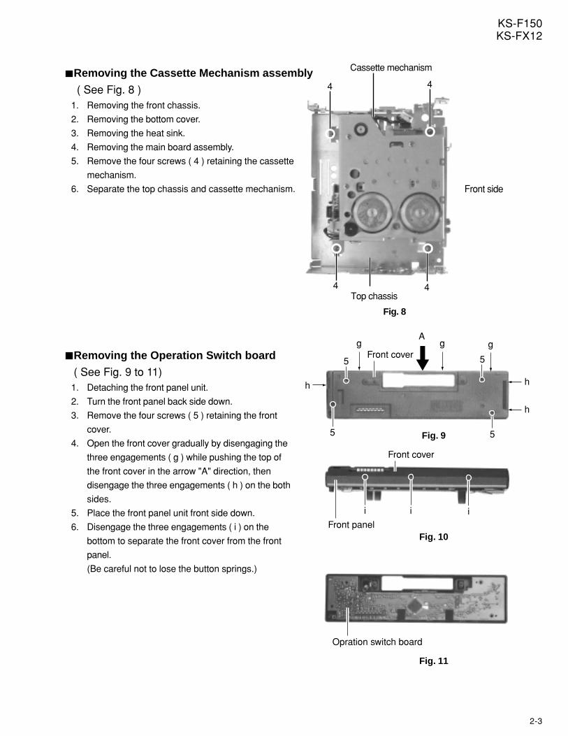
Removing the Cassette Mechanism assembly
( See Fig. 8 )1. Removing the front chassis.
2. Removing the bottom cover.
3. Removing the heat sink.
4. Removing the main board assembly.
5. Remove the four screws ( 4 ) retaining the cassette
mechanism.
6. Separate the top chassis and cassette mechanism.
Cassette mechanism
Front side
Top chassis
Fig. 8
44
4 4
Removing the Operation Switch board
( See Fig. 9 to 11)1. Detaching the front panel unit.
2. Turn the front panel back side down.
3. Remove the four screws ( 5 ) retaining the front
cover.
4. Open the front cover gradually by disengaging the
three engagements ( g ) while pushing the top of
the front cover in the arrow "A" direction, then
disengage the three engagements ( h ) on the both
sides.
5. Place the front panel unit front side down.
6. Disengage the three engagements ( i ) on the
bottom to separate the front cover from the front
panel.
(Be careful not to lose the button springs.)
2-4
KS-F150KS-FX12
Fig. 14
8
8
8
8
Chassis assembly
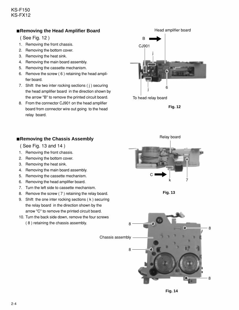
Removing the Head Amplifier Board
( See Fig. 12 )1. Removing the front chassis.
2. Removing the bottom cover.
3. Removing the heat sink.
4. Removing the main board assembly.
5. Removing the cassette mechanism.
6. Remove the screw ( 6 ) retaining the head ampli-
fier board.
7. Shift the two inter rocking sections ( j ) securing
the head amplifier board in the direction shown by
the arrow "B" to remove the printed circuit board.
8. From the connector CJ901 on the head amplifier
board from connector wire out going to the head
relay board.
Removing the Chassis Assembly
( See Fig. 13 and 14 )1. Removing the front chassis.
2. Removing the bottom cover.
3. Removing the heat sink.
4. Removing the main board assembly.
5. Removing the cassette mechanism.
6. Removing the head amplifier board.
7. Turn the left side to cassette mechanism.
8. Remove the screw ( 7 ) retaining the relay board.
9. Shift the one inter rocking sections ( k ) securing
the relay board in the direction shown by the
arrow "C" to remove the printed circuit board.
10. Turn the back side down, remove the four screws
( 8 ) retaining the chassis assembly.
Fig. 12
To head relay board
Head amplifier board
CJ901
6
j
j
B
Fig. 13
Relay board
C7k
2-5
KS-F150KS-FX12
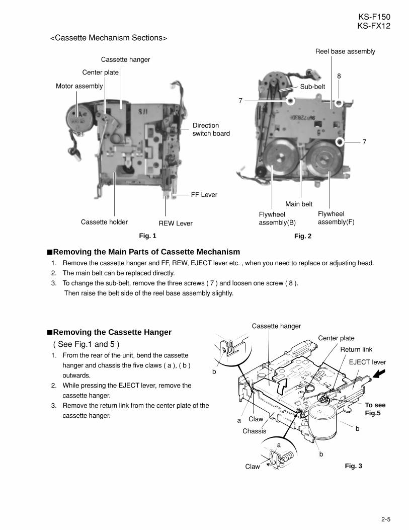
<Cassette Mechanism Sections>
Direction switch board
Motor assembly
Cassette hanger
Center plate
Cassette holder REW Lever
FF Lever
Fig. 1
Main belt
Sub-belt
Reel base assembly
Flywheel assembly(B)
Flywheel assembly(F)
Fig. 2
7
8
7
Removing the Main Parts of Cassette Mechanism1. Remove the cassette hanger and FF, REW, EJECT lever etc. , when you need to replace or adjusting head.
2. The main belt can be replaced directly.
3. To change the sub-belt, remove the three screws ( 7 ) and loosen one screw ( 8 ).
Then raise the belt side of the reel base assembly slightly.
Fig. 3
To see Fig.5
Cassette hanger
Center plate
Return link
EJECT lever
Chassis
Claw
Claw
a
a
b
b
b
Removing the Cassette Hanger
( See Fig.1 and 5 )1. From the rear of the unit, bend the cassette
hanger and chassis the five claws ( a ), ( b )
outwards.
2. While pressing the EJECT lever, remove the
cassette hanger.
3. Remove the return link from the center plate of the
cassette hanger.
2-6
KS-F150KS-FX12
Cassette hanger
Return link EJECT lever
EJECT L.Spring
EJECT C.Spring
EJECT cam
The convex section should be between the cassette hanger and EJECT cam .
Fig. 5
Push
b
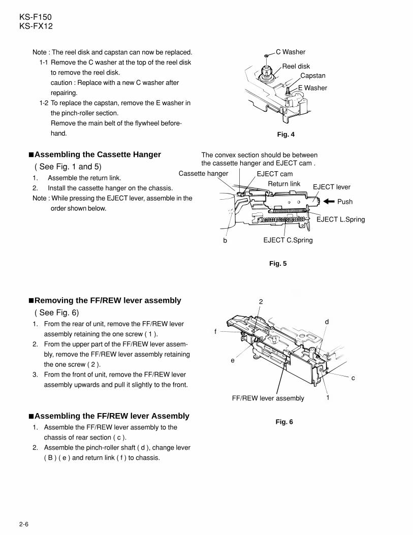
Note : The reel disk and capstan can now be replaced.
1-1 Remove the C washer at the top of the reel disk
to remove the reel disk.
caution : Replace with a new C washer after
repairing.
1-2 To replace the capstan, remove the E washer in
the pinch-roller section.
Remove the main belt of the flywheel before-
hand.
Assembling the Cassette Hanger
( See Fig. 1 and 5)1. Assemble the return link.
2. Install the cassette hanger on the chassis.
Note : While pressing the EJECT lever, assemble in the
order shown below.
Removing the FF/REW lever assembly
( See Fig. 6)1. From the rear of unit, remove the FF/REW lever
assembly retaining the one screw ( 1 ).
2. From the upper part of the FF/REW lever assem-
bly, remove the FF/REW lever assembly retaining
the one screw ( 2 ).
3. From the front of unit, remove the FF/REW lever
assembly upwards and pull it slightly to the front.
Assembling the FF/REW lever Assembly1. Assemble the FF/REW lever assembly to the
chassis of rear section ( c ).
2. Assemble the pinch-roller shaft ( d ), change lever
( B ) ( e ) and return link ( f ) to chassis.
C Washer
Reel diskCapstan
E Washer
Fig. 4
Fig. 6
FF/REW lever assembly
2
1
2
f
e
c
d
2-7
KS-F150KS-FX12
Fig. 10Fig. 10
Back side view of the reel base assembly
Fig. 9
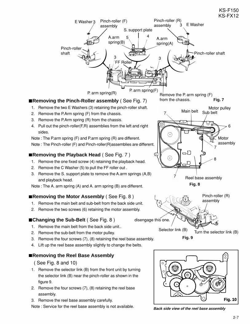
Pinch-roller (R) assembly
Selector link (B) Turn the selector link (B)
disengage this one.
Fig. 8
Main belt Sub belt
Reel base assembly
Motor assembly
Motor pulley7
7
7
8
6
Fig. 7
P. arm spring(F)P. arm spring(R)
33
E WasherE Washer
Pinch-roller shaft Pinch-roller shaft
Pinch-roller (R) assembly
Pinch-roller (F) assembly
A.arm spring(A)
A.arm spring(B)
Remove the P. arm spring (F) from the chassis.
S. support plate
FF Roller
5
3 3
4
Removing the Pinch-Roller assembly ( See Fig. 7)1. Remove the two E Washers (3) retaining the pinch-roller shaft.
2. Remove the P.Arm spring (F) from the chassis.
3. Remove the P.Arm spring (R) from the chassis.
4. Pull out the pinch-roller(F,R) assemblies from the left and right
sides.
Note : The P.arm spring (F) and P.arm spring (R) are different.
Note : The Pinch-roller (F) and Pinch-roller(R)assemblies are different.
Removing the Playback Head ( See Fig. 7 )1. Remove the one fixed screw (4) retaining the playback head.
2. Remove the C Washer (5) to pull the FF roller out .
3. Remove the S. support plate to remove the A.arm springs (A,B)
and playback head.
Note : The A. arm spring (A) and A. arm spring (B) are different.
Removing the Motor Assembly ( See Fig. 8 )1. Remove the main belt and sub-belt from the back side unit.
2. Remove the two screws (6) retaining the motor assembly.
Changing the Sub-Belt ( See Fig. 8 )1. Remove the main belt from the back side unit..
2. Remove the sub-belt from the motor pulley.
3. Remove the four screws (7), (8) retaining the reel base assembly.
4. Lift up the reel base assembly slightly to change the belts.
Removing the Reel Base Assembly
( See Fig. 8 and 10)1. Remove the selector link (B) from the front unit by turning
the selector link (B) near the pinch-roller as shown in the
figure 9.
2. Remove the four screws (7), (8) retaining the reel base
assembly.
3. Remove the reel base assembly carefully.
Note : Service for the reel base assembly is not available.
2-8
KS-F150KS-FX12
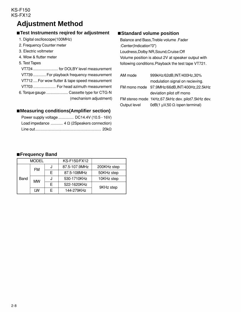
Adjustment MethodTest Instruments reqired for adjustment
1. Digital osclloscope(100MHz)
2. Frequency Counter meter
3. Electric voltmeter
4. Wow & flutter meter
5. Test Tapes
VT724 ....................... for DOLBY level measurement
VT739 ............ For playback frequency measurement
VT712 ....For wow flutter & tape speed measurement
VT703 ..................... For head azimuth measurement
6. Torque gauge .................... Cassette type for CTG-N
(mechanism adjustment)
Measuring conditions(Amplifier section)Power supply voltage .............. DC14.4V (10.5 - 16V)
Load impedance ........... 4 Ω (2Speakers connection)
Line out ............................................................ 20kΩ
Standard volume positionBalance and Bass,Treble volume .Fader
:Center(Indication"0")
Loudness,Dolby NR,Sound,Cruise:Off
Volume position is about 2V at speaker output with
following conditions.Playback the test tape VT721.
AM mode 999kHz/62dB,INT/400Hz,30%
modulation signal on recieving.
FM mono mode 97.9MHz/66dB,INT/400Hz,22.5kHz
deviation pilot off mono
FM stereo mode 1kHz,67.5kHz dev. pilot7.5kHz dev.
Output level 0dB(1 µV,50 Ω /open terminal)
Frequency BandMODEL KS-F150/FX12
FMJ 87.5-107.9MHz 200KHz step
E 87.5-108MHz 50KHz step
BandMW
J 530-1710KHz 10KHz step
E 522-1620KHz9KHz step
LW E 144-279KHz
2-9
KS-F150KS-FX12
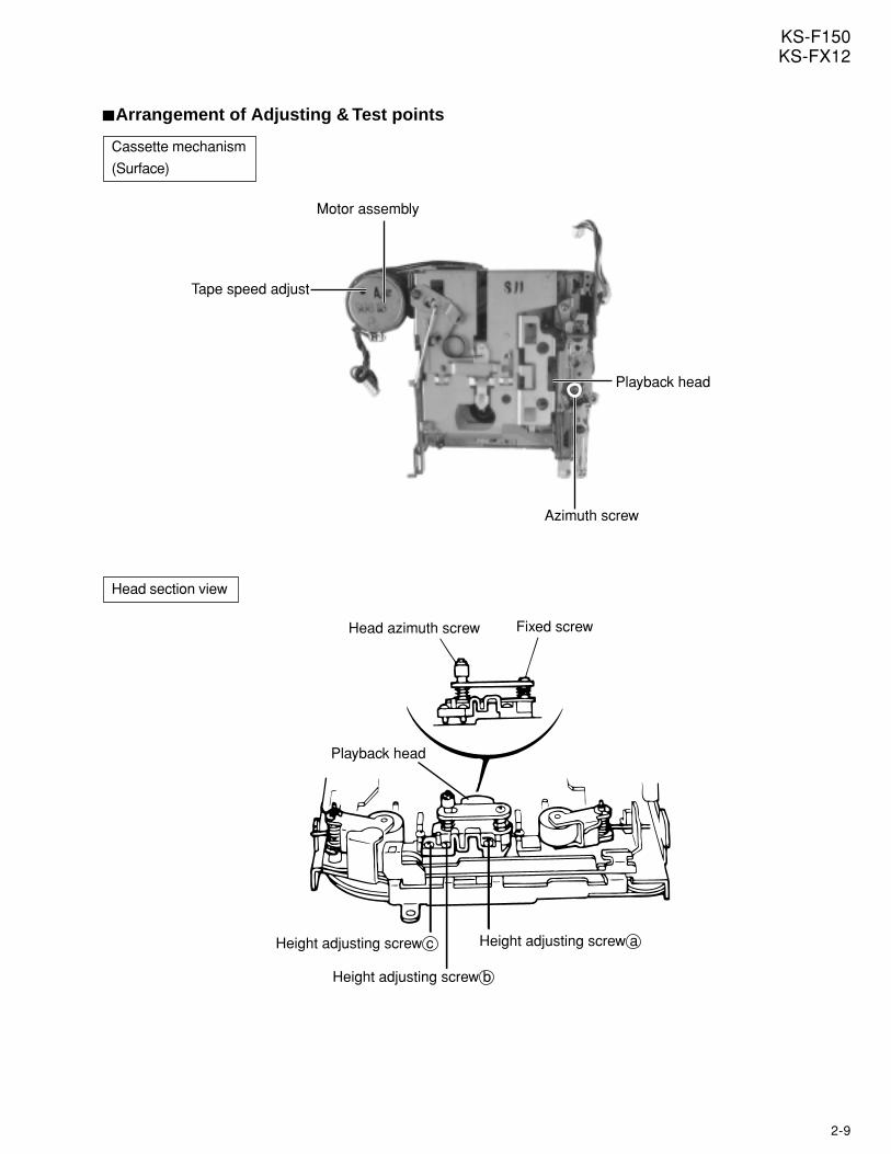
Arrangement of Adjusting & Test points
Head section view
Cassette mechanism
(Surface)
Tape speed adjust
Motor assembly
Playback head
Azimuth screw
Head azimuth screw Fixed screw
Height adjusting screw c
Height adjusting screw b
Height adjusting screw a
Playback head
2-10
KS-F150KS-FX12
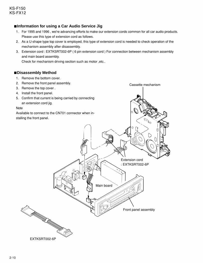
Extension cord: EXTKSRT002-6P
EXTKSRT002-6P
Front panel assembly
Main board
Cassette mechanism
Information for using a Car Audio Service Jig1. For 1995 and 1996 , we're advancing efforts to make our extension cords common for all car audio products.
Please use this type of extension cord as follows.
2. As a U-shape type top cover is employed, this type of extension cord is needed to check operation of the
mechanism assembly after disassembly.
3. Extension cord : EXTKSRT002-6P ( 6 pin extension cord ) For connection between mechanism assembly
and main board assembly.
Check for mechanism driving section such as motor ,etc..
Disassembly Method1. Remove the bottom cover.
2. Remove the front panel assembly.
3. Remove the top cover .
4. Install the front panel.
5. Confirm that current is being carried by connecting
an extension cord jig.
Note
Available to connect to the CN701 connector when in-
stalling the front panel.
2-11
KS-F150KS-FX12
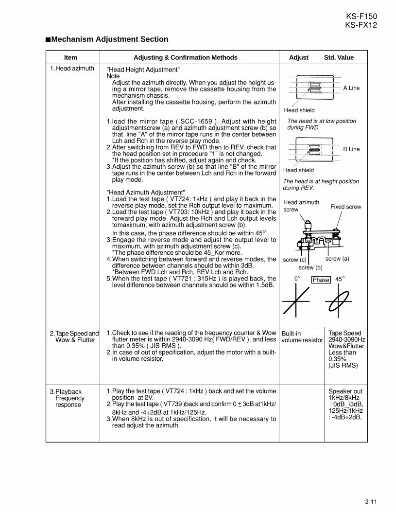
Mechanism Adjustment Section
Item Adjusting & Confirmation Methods Adjust Std. Value
"Head Height Adjustment"Note
Adjust the azimuth directly. When you adjust the height us-ing a mirror tape, remove the cassette housing from themechanism chassis.After installing the cassette housing, perform the azimuthadjustment.
1.load the mirror tape ( SCC-1659 ). Adjust with heightadjustmentscrew (a) and azimuth adjustment screw (b) sothat line "A" of the mirror tape runs in the center betweenLch and Rch in the reverse play mode.
2.After switching from REV to FWD then to REV, check thatthe head position set in procedure "1" is not changed.*If the position has shifted, adjust again and check.
3.Adjust the azimuth screw (b) so that line "B" of the mirrortape runs in the center between Lch and Rch in the forwardplay mode.
"Head Azimuth Adjustment"1.Load the test tape ( VT724: 1kHz ) and play it back in the
reverse play mode. set the Rch output level to maximum.2.Load the test tape ( VT703: 10kHz ) and play it back in the
forward play mode. Adjust the Rch and Lch output levelstomaximum, with azimuth adjustment screw (b).In this case, the phase difference should be within 45 .
3.Engage the reverse mode and adjust the output level tomaximum, with azimuth adjustment screw (c).*The phase difference should be 45_Kor more.
4.When switching between forward and reverse modes, thedifference between channels should be within 3dB.*Between FWD Lch and Rch, REV Lch and Rch.
5.When the test tape ( VT721 : 315Hz ) is played back, thelevel difference between channels should be within 1.5dB.
1.Check to see if the reading of the frequency counter & Wowflutter meter is within 2940-3090 Hz( FWD/REV ), and lessthan 0.35% ( JIS RMS ).
2.In case of out of specification, adjust the motor with a built-in volume resistor.
1.Play the test tape ( VT724 : 1kHz ) back and set the volumeposition at 2V.
2.Play the test tape ( VT739 )back and confirm 0 + 3dB at1kHz/-8kHz and -4+2dB at 1kHz/125Hz.
3.When 8kHz is out of specification, it will be necessary toread adjust the azimuth.
Head shield
Head shield
The head is at low position during FWD.
The head is at height position during REV.
A Line
B Line
Phase
screw (c) screw (a)
screw (b)
Head azimuth screw Fixed screw
0 45
Built-involume resistor
Tape Speed2940-3090HzWow&FlutterLess than0.35%(JIS RMS)
Speaker out1kHz/8kHz : 0dB_3dB,125Hz/1kHz: -4dB+2dB,
1.Head azimuth
2.Tape Speed andWow & Flutter
3.PlaybackFrequencyresponse
2-12
KS-F150KS-FX12
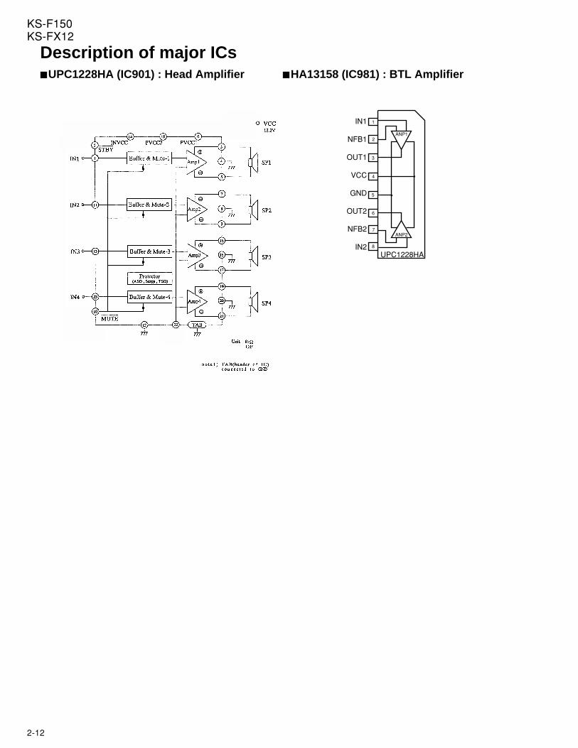
Description of major ICsUPC1228HA (IC901) : Head Amplifier HA13158 (IC981) : BTL Amplifier
ANP1
ANP2
UPC1228HA
1
2
3
4
5
6
7
8
IN1
NFB1
OUT1
VCC
GND
OUT2
NFB2
IN2
2-13
KS-F150KS-FX12
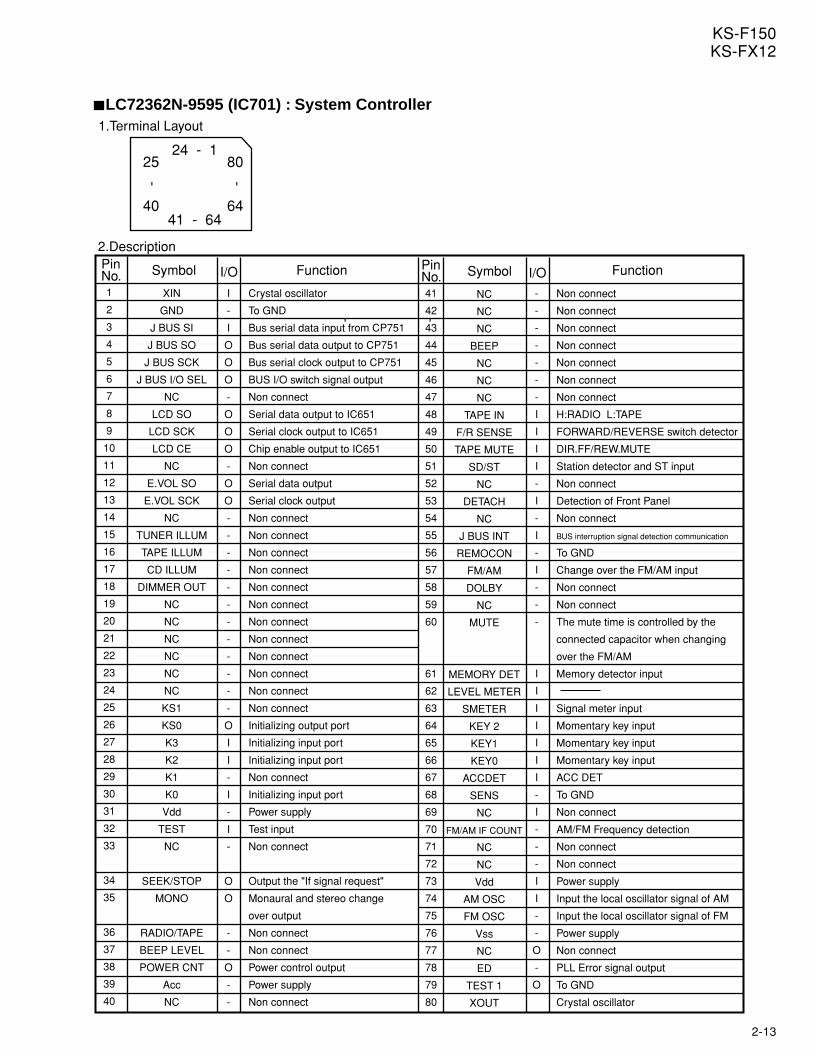
LC72362N-9595 (IC701) : System Controller
1
2
3
4
5
6
7
8
9
10
11
12
13
14
15
16
17
18
19
20
21
22
23
24
25
26
27
28
29
30
31
32
33
34
35
36
37
38
39
40
41
42
43
44
45
46
47
48
49
50
51
52
53
54
55
56
57
58
59
60
61
62
63
64
65
66
67
68
69
70
71
72
73
74
75
76
77
78
79
80
XIN
GND
J BUS SI
J BUS SO
J BUS SCK
J BUS I/O SEL
NC
LCD SO
LCD SCK
LCD CE
NC
E.VOL SO
E.VOL SCK
NC
TUNER ILLUM
TAPE ILLUM
CD ILLUM
DIMMER OUT
NC
NC
NC
NC
NC
NC
KS1
KS0
K3
K2
K1
K0
Vdd
TEST
NC
SEEK/STOP
MONO
RADIO/TAPE
BEEP LEVEL
POWER CNT
Acc
NC
NC
NC
NC
BEEP
NC
NC
NC
TAPE IN
F/R SENSE
TAPE MUTE
SD/ST
NC
DETACH
NC
J BUS INT
REMOCON
FM/AM
DOLBY
NC
MUTE
MEMORY DET
LEVEL METER
SMETER
KEY 2
KEY1
KEY0
ACCDET
SENS
NC
FM/AM IF COUNT
NC
NC
Vdd
AM OSC
FM OSC
Vss
NC
ED
TEST 1
XOUT
I
-
I
O
O
O
-
O
O
O
-
O
O
-
-
-
-
-
-
-
-
-
-
-
-
O
I
I
-
I
-
I
-
O
O
-
-
O
-
-
-
-
-
-
-
-
-
I
I
I
I
-
I
-
I
-
I
-
-
-
I
I
I
I
I
I
I
-
I
-
-
-
I
I
-
-
O
-
O
Crystal oscillator
To GND
Bus serial data input from CP751
Bus serial data output to CP751
Bus serial clock output to CP751
BUS I/O switch signal output
Non connect
Serial data output to IC651
Serial clock output to IC651
Chip enable output to IC651
Non connect
Serial data output
Serial clock output
Non connect
Non connect
Non connect
Non connect
Non connect
Non connect
Non connect
Non connect
Non connect
Non connect
Non connect
Non connect
Initializing output port
Initializing input port
Initializing input port
Non connect
Initializing input port
Power supply
Test input
Non connect
Output the "If signal request"
Monaural and stereo change
over output
Non connect
Non connect
Power control output
Power supply
Non connect
Non connect
Non connect
Non connect
Non connect
Non connect
Non connect
Non connect
H:RADIO L:TAPE
FORWARD/REVERSE switch detector
DIR.FF/REW.MUTE
Station detector and ST input
Non connect
Detection of Front Panel
Non connect
BUS interruption signal detection communication
To GND
Change over the FM/AM input
Non connect
Non connect
The mute time is controlled by the
connected capacitor when changing
over the FM/AM
Memory detector input
Signal meter input
Momentary key input
Momentary key input
Momentary key input
ACC DET
To GND
Non connect
AM/FM Frequency detection
Non connect
Non connect
Power supply
Input the local oscillator signal of AM
Input the local oscillator signal of FM
Power supply
Non connect
PLL Error signal output
To GND
Crystal oscillator
PinNo. Symbol I/O Function Pin
No. Symbol I/O Function
1.Terminal Layout
2.Description
- -
41 - 64
24 - 125
40
80
64
- -
2-14
KS-F150KS-FX12
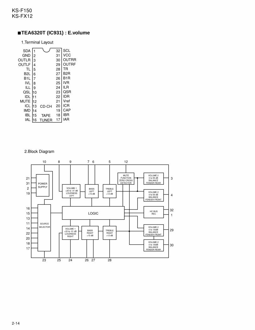
TEA6320T (IC931) : E.volume
TREBLELEFT
+12 dB
12345678910111213141516
32313029282726252423222120191817
SDAGND
OUTLROUTLF
TLB2LB1LIVLILL
QSLIDL
MUTEICLIMDIBLIAL
SCLVCCOUTRROUTRFTRB2RB1RIVRILRQSRIDRVrefICRCAPIBRIAR
CD-CH
TAPETUNER
POWERSUPPLY
SOURCE
SELECTOR
VOLUME 1+20 to -31 dBLOUDNESS
LEFT
BASSLEFT
+15 dB
BASSRIGHT+15 dB
TREBLERIGHT+12 dB
MUTEFUNCTION
ZERO CROSSDETECTOR
VOLUME 20 to 55 dBBALANCE
FENDER REAR
VOLUME 20 to 55 dBBALANCE
FENDER FRONT
HC BUSREC
VOLUME 20 to -55dBBALANCE
FENDER FRONT
VOLUME 20 to -55dBBALANCE
FENDER REAR
VOLUME 1+20 to -31 dBLOUDNESS
RIGHT
LOGIC
21
16
22
14
23 25 24 26 27 28
30
29
1
32
3
4
10 8 9 7 6 5 12
1.Terminal Layout
2.Block Diagram
2
19
31
15
13
11
20
18
17
2-15
KS-F150KS-FX12
1
2
3
4
5
6
7
8
9
10
11
12
13
14
15
16
17
18
19
20
21
22
23
24
25
26
27
28
29
30
31
32
SDA
GND
OUTLR
OUTLF
TL
B2L
B1L
IVL
ILL
QSL
IDL
MUTE
ICL
IMO
IBL
IAL
IAR
IBR
CAP
ICR
Vref
IDR
QSR
ILR
IVR
B1R
B2R
TR
OUTRF
OUTRR
Vcc
SCL
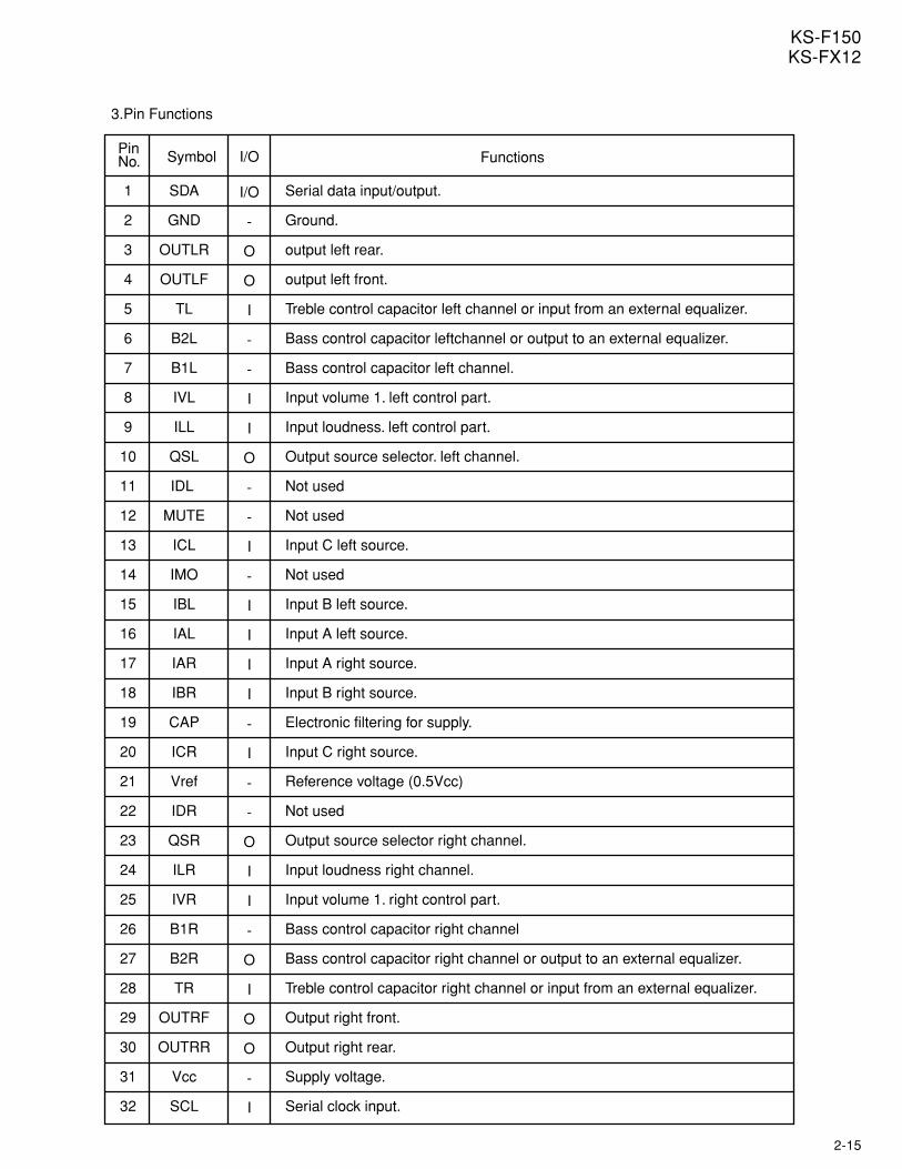
Serial data input/output.
Ground.
output left rear.
output left front.
Treble control capacitor left channel or input from an external equalizer.
Bass control capacitor leftchannel or output to an external equalizer.
Bass control capacitor left channel.
Input volume 1. left control part.
Input loudness. left control part.
Output source selector. left channel.
Not used
Not used
Input C left source.
Not used
Input B left source.
Input A left source.
Input A right source.
Input B right source.
Electronic filtering for supply.
Input C right source.
Reference voltage (0.5Vcc)
Not used
Output source selector right channel.
Input loudness right channel.
Input volume 1. right control part.
Bass control capacitor right channel
Bass control capacitor right channel or output to an external equalizer.
Treble control capacitor right channel or input from an external equalizer.
Output right front.
Output right rear.
Supply voltage.
Serial clock input.
I/O
-
O
O
I
-
-
I
I
O
-
-
I
-
I
I
I
I
-
I
-
-
O
I
I
-
O
I
O
O
-
I
PinNo. Symbol I/O Functions
3.Pin Functions
2-16
KS-F150KS-FX12
NC TUNER FM/AM POWERCNT
5V REMOTE MEMORY NC 9V AM FM GND
1
2
3
4
5
6
7
8
9
10
11
12
NC
TUNER
FM/AM
POWERCNT
5V
REMOTE
MEMORY
NC
9V
AM
FM
GND
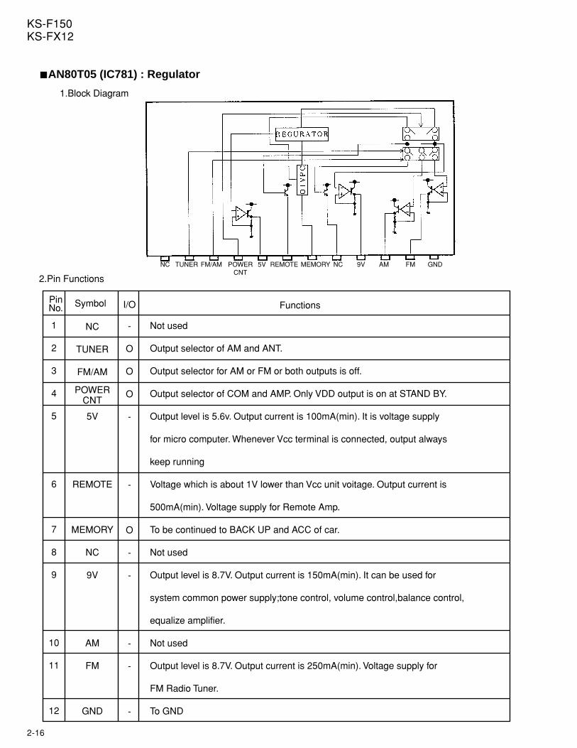
Not used
Output selector of AM and ANT.
Output selector for AM or FM or both outputs is off.
Output selector of COM and AMP. Only VDD output is on at STAND BY.
Output level is 5.6v. Output current is 100mA(min). It is voltage supply
for micro computer. Whenever Vcc terminal is connected, output always
keep running
Voltage which is about 1V lower than Vcc unit voitage. Output current is
500mA(min). Voltage supply for Remote Amp.
To be continued to BACK UP and ACC of car.
Not used
Output level is 8.7V. Output current is 150mA(min). It can be used for
system common power supply;tone control, volume control,balance control,
equalize amplifier.
Not used
Output level is 8.7V. Output current is 250mA(min). Voltage supply for
FM Radio Tuner.
To GND
PinNo. Symbol Functions
-
O
O
O
-
-
O
-
-
-
-
-
I/O
1.Block Diagram
2.Pin Functions
AN80T05 (IC781) : Regulator
2-17
KS-F150KS-FX12
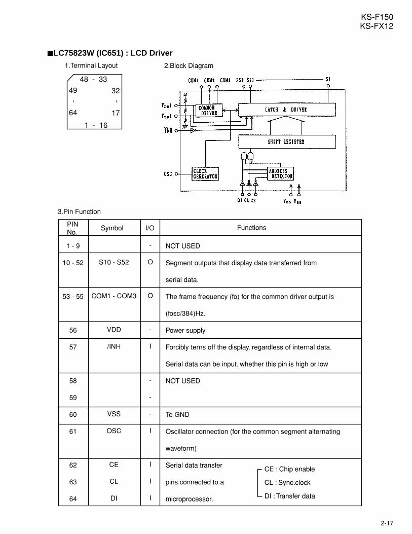
LC75823W (IC651) : LCD Driver
1 - 16
48 - 33
49
64
32
17
PINNo.
1 - 9
10 - 52
53 - 55
56
57
58
59
60
61
62
63
64
S10 - S52
COM1 - COM3
VDD
/INH
VSS
OSC
CE
CL
DI
NOT USED
Segment outputs that display data transferred from
serial data.
The frame frequency (fo) for the common driver output is
(fosc/384)Hz.
Power supply
Forcibly terns off the display. regardless of internal data.
Serial data can be input. whether this pin is high or low
NOT USED
To GND
Oscillator connection (for the common segment alternating
waveform)
Serial data transfer
pins.connected to a
microprocessor.
-
O
O
-
I
-
-
-
I
I
I
I
CE : Chip enable
CL : Sync.clock
DI : Transfer data
Symbol I/O Functions
1.Terminal Layout 2.Block Diagram
3.Pin Function
- -
2-18
KS-F150KS-FX12
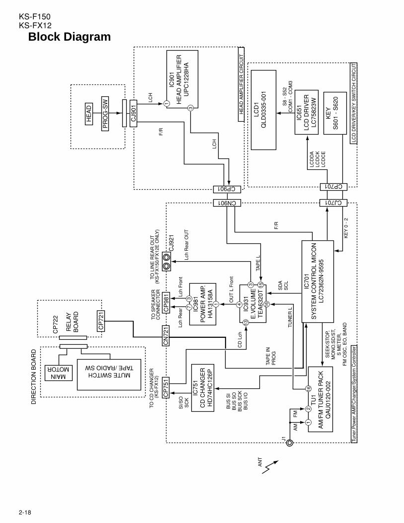
Block Diagram
HE
AD
IC90
1H
EA
D A
MP
LIF
IER
UP
C12
28H
A
IC98
1P
OW
ER
AM
P.H
A13
158A
IC75
1C
D C
HA
NG
ER
HD
74H
C12
6P
IC93
1E
.VO
LUM
ET
EA
6320
T
IC70
1S
YS
TE
M C
ON
TR
OL
MIC
ON
LC72
362N
-959
5T
U1
AM
/FM
TU
NE
R P
AC
KQ
AU
0120
-002
LCD
1Q
LD03
35-0
01
IC65
1LC
D D
RIV
ER
LC75
823W
KE
YS
601
- S
620
MAINMOTOR
MUTE SWITCHTAPE /RADIO SW
SE
EK
/STO
P,M
ON
O.S
D/S
T,S
ME
TE
R,
FM
OS
C, E
O, B
AN
DTU
NE
R L
TAP
E IN
PR
OG
BU
S S
IB
US
SO
BU
S S
CK
BU
S I/
O
OU
T L
Fro
nt
Lch
Fron
tLc
h R
ear
Lch
Rea
r O
UT
SD
AS
CL
CN901
CP
721
CN
721
CP
751
KE
Y 0
- 2
CJ701
LCD
DA
LCD
CK
LCD
CE
F/R
S8
- S
52C
OM
1 -
CO
M3
CP701
TAP
E L
LCH
F/R
LCH
CP901
CJ9
01
J1
FM
TO S
PE
AK
ER
CO
NN
EC
TOR
TO L
INE
RE
AR
OU
T (
KS
-FX
150/
FX
12E
ON
LY)
Tune
r.Pow
er A
MP.
Cha
nger
/Sys
tem
Con
trol
ler
LCD
DR
IVE
R/K
EY
SW
ITC
H C
IRC
UT
HE
AD
AM
PLI
FIE
R C
IRC
UIT
CJ9
21
CP
722
DIR
EC
TIO
N B
OA
RD
RE
LAY
BO
AR
D
AM
CP
981
SI/S
OS
CK
TO C
D C
HA
NG
ER
(
KS
-FX
12)
CD
Lch
216
1
1615
4
3
1
37
13
PR
OG
-SW
3
1
AN
T
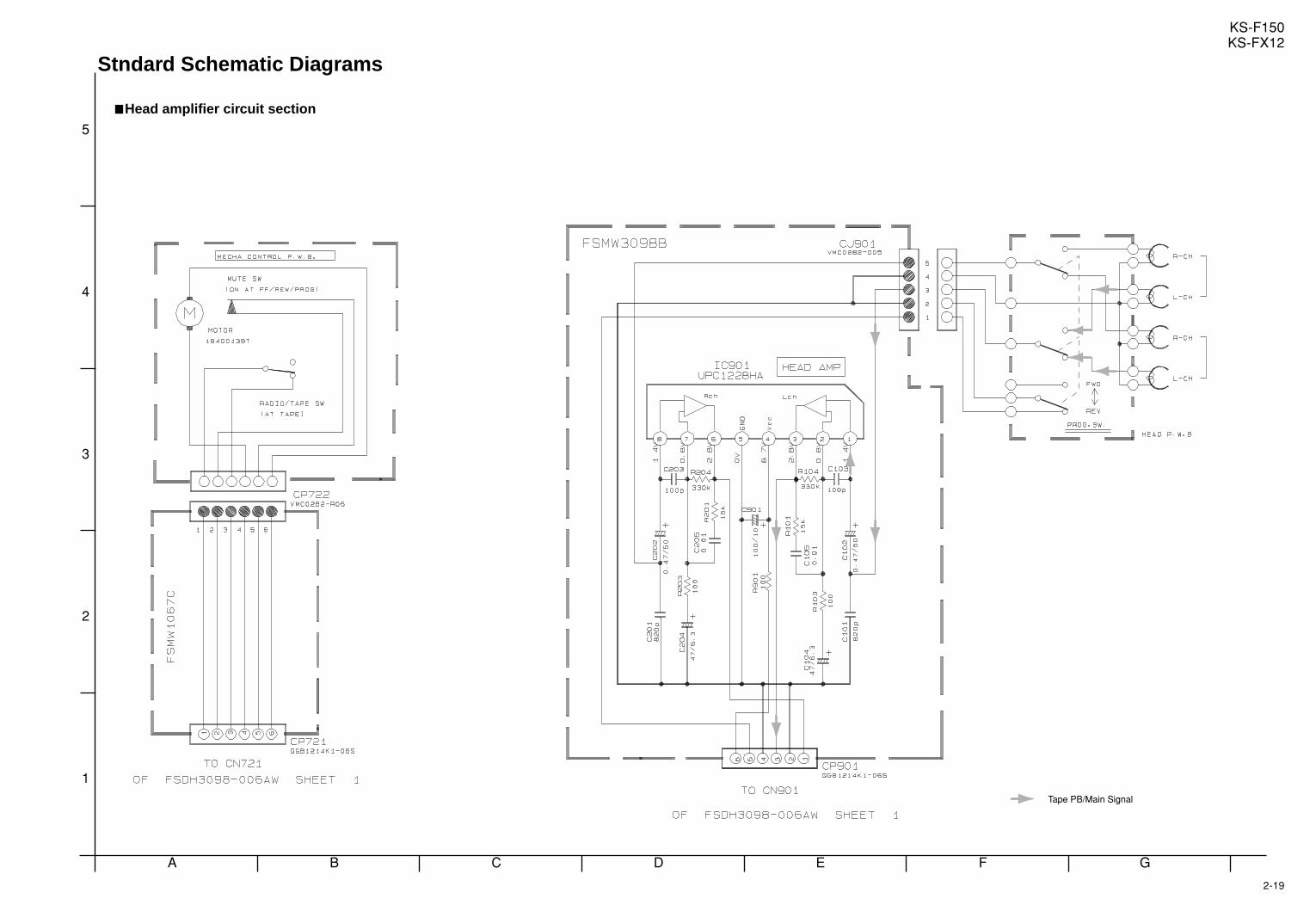
2-19
KS-F150KS-FX12
A B C D E F G
3
4
5
2
1
Head amplifier circuit section
Stndard Schematic Diagrams
Tape PB/Main Signal
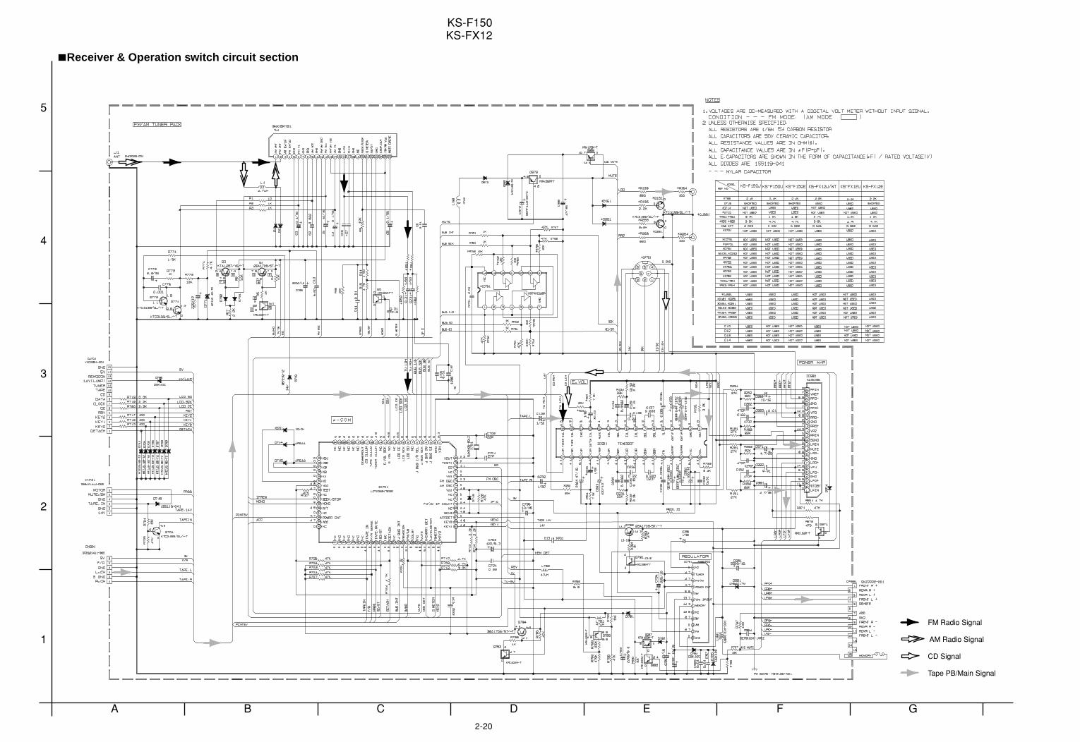
2-20
KS-F150KS-FX12
A B C D E F G
3
4
5
2
1
Receiver & Operation switch circuit section
FM Radio Signal
Tape PB/Main Signal
CD Signal
AM Radio Signal
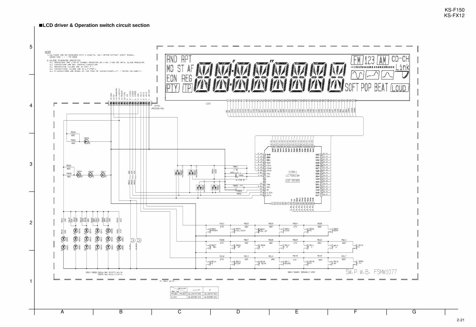
2-21
KS-F150KS-FX12
A B C D E F G
3
4
5
2
1
LCD driver & Operation switch circuit section
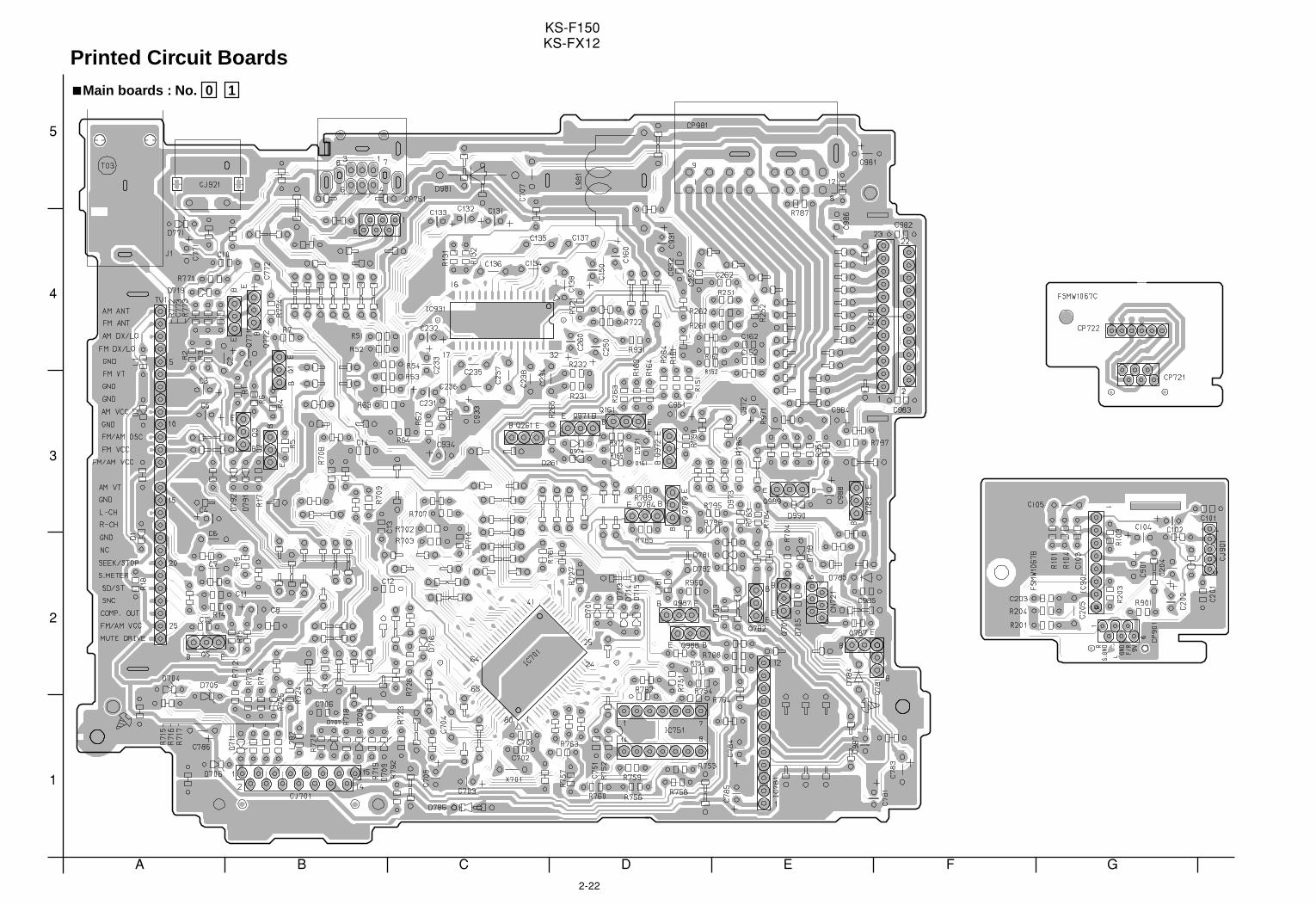
2-22
KS-F150KS-FX12
A B C D E F G
3
4
5
2
1
Printed Circuit BoardsMain boards : No. 0 1
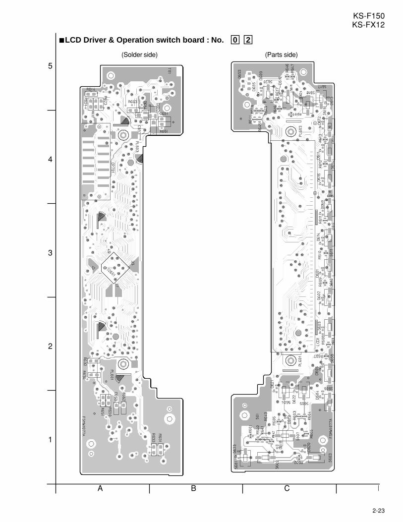
2-23
KS-F150KS-FX12
A B C D
3
4
5
2
1
LCD Driver & Operation switch board : No. 0 2
(Solder side) (Parts side)
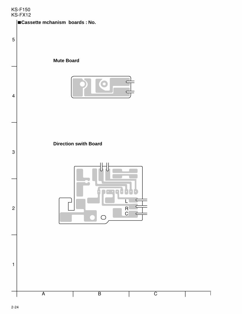
2-24
KS-F150KS-FX12
A B C D
3
4
5
2
1
L
RC
Cassette mchanism boards : No.
Direction swith Board
Mute Board
3-1
KS-F150KS-FX12
PARTS LIST
- Contents -
Exploded view of general assembly and parts list ------------------------------------------ 3 - 2
Cassette mechanism assembly and parts list ----------------------------------------------- 3 - 5
Electrical parts list ----------------------------------------------------------------------------------- 3 - 8
Packing materials and accessories parts list------------------------------------------------- 3 - 12
* All printed circuit boards and its assemblies are not available as service parts.
[ KS-FX12 ]
[ KS-FX12WT ]
[ KS-F150 ]
Area Suffix
[KS-F150]
J .......... Northern America
Area Suffix
[KS-FX12]
J ......... Northern America
E ...... Continental Europe
Area Suffix
[KS-FX12WT]
J .......... Northern America
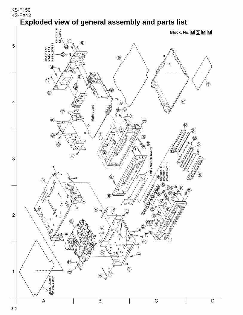
3-2
KS-F150KS-FX12
A B C D
3
4
5
2
1
Mai
n b
oar
d
LC
D /
Sw
itch
bo
ard
30
28
5052
6061
62K
S-F
X12
WT
V
er. J
On
ly
KS
-FX
12 /
EK
S-F
X12
/ J
KS
-FX
12W
T /
J KS
-FX
12 /
EK
S-F
150
/ J
KS
-FX
12 /
EK
S-F
X12
/ J
KS
-FX
12W
T /
J
Block: No. M 1 M M
Exploded view of general assembly and parts list
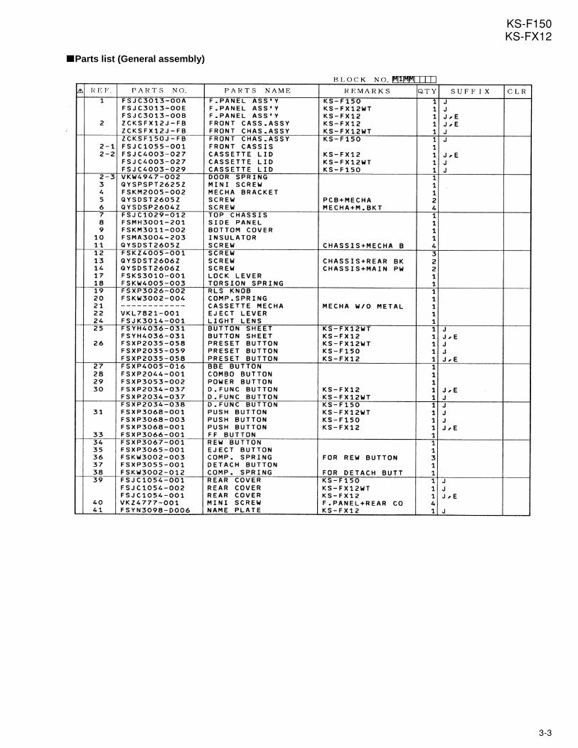
3-3
KS-F150KS-FX12
Parts list (General assembly)
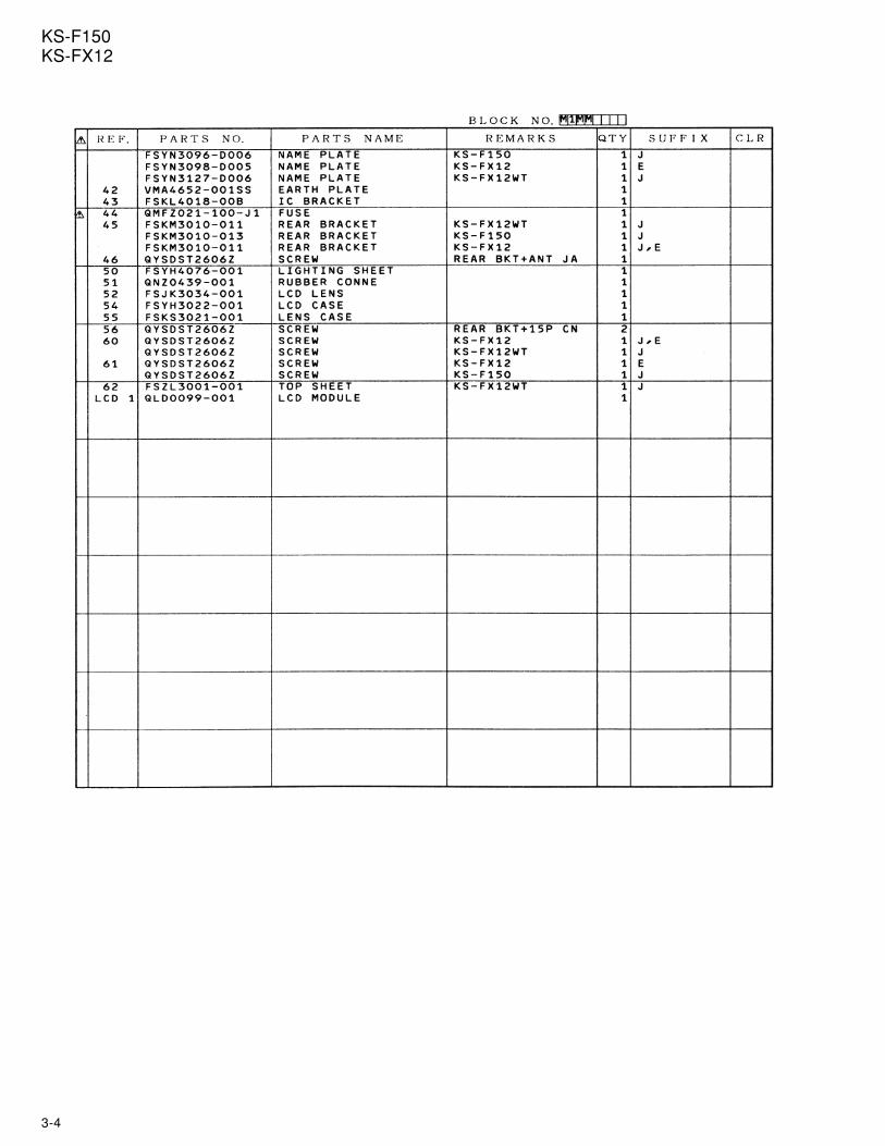
3-4
KS-F150KS-FX12
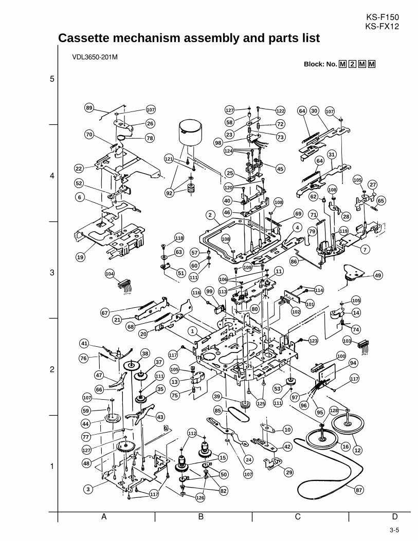
3-5
KS-F150KS-FX12
A B C D
3
4
5
2
1
123 103
114
101
102
104
107
59
66
47
76
44
127
77
48
3117
12682
50
15
112
107
24
29
85
3975
13
105
117
2068
2167
19
6
52
22
41
1
42
10
125 111
53
97
87
1216
1289596
117
94100
123
74
103
35
43
111
37
38
70
89
26
78
107
121
92
127 122
72
73
45
108
118
63
51
58
23
98124
25
120
40
2 46
108
57
106
116 11399
60
80
111
10911
105
14
49
28
7
86
65
11979 4
69 71
62
27 105
108
30 107
64
64
31
Cassette mechanism assembly and parts listVDL3650-201M
Block: No. M 2 M M
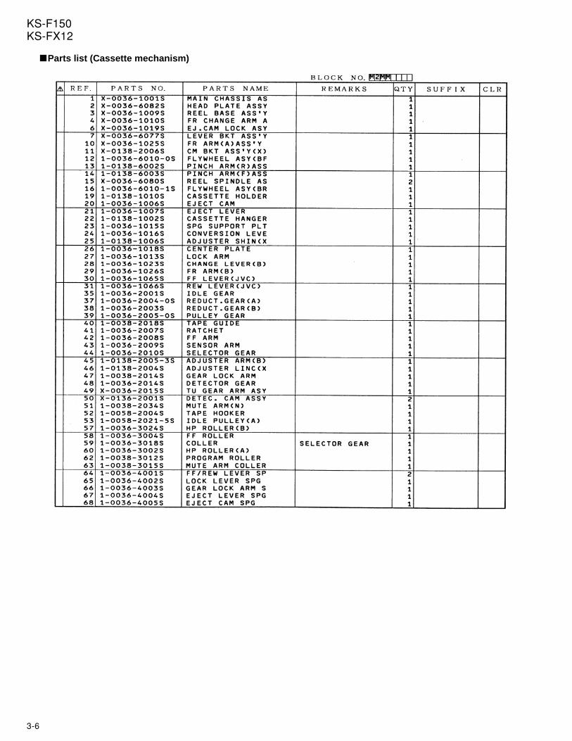
3-6
KS-F150KS-FX12
Parts list (Cassette mechanism)
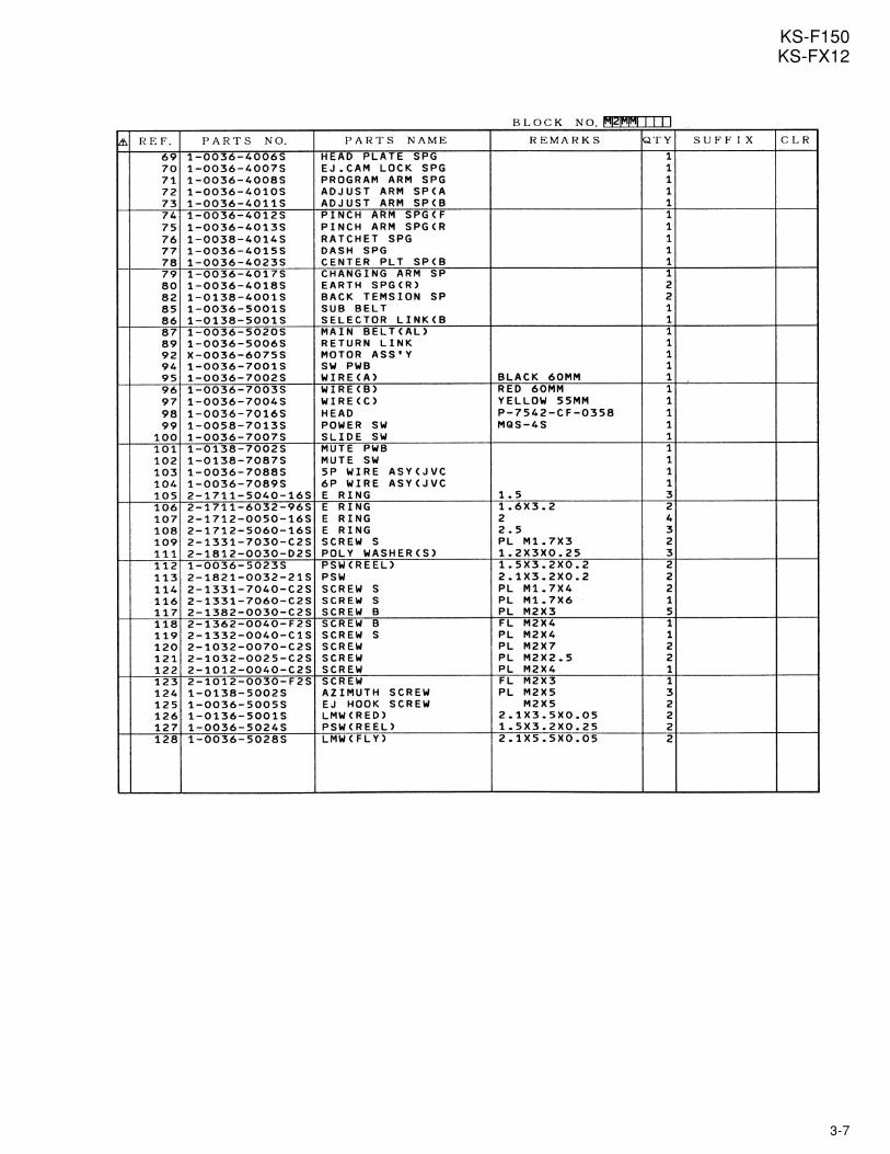
3-7
KS-F150KS-FX12
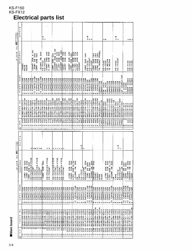
3-8
KS-F150KS-FX12
Electrical parts listM
ain
bo
ard
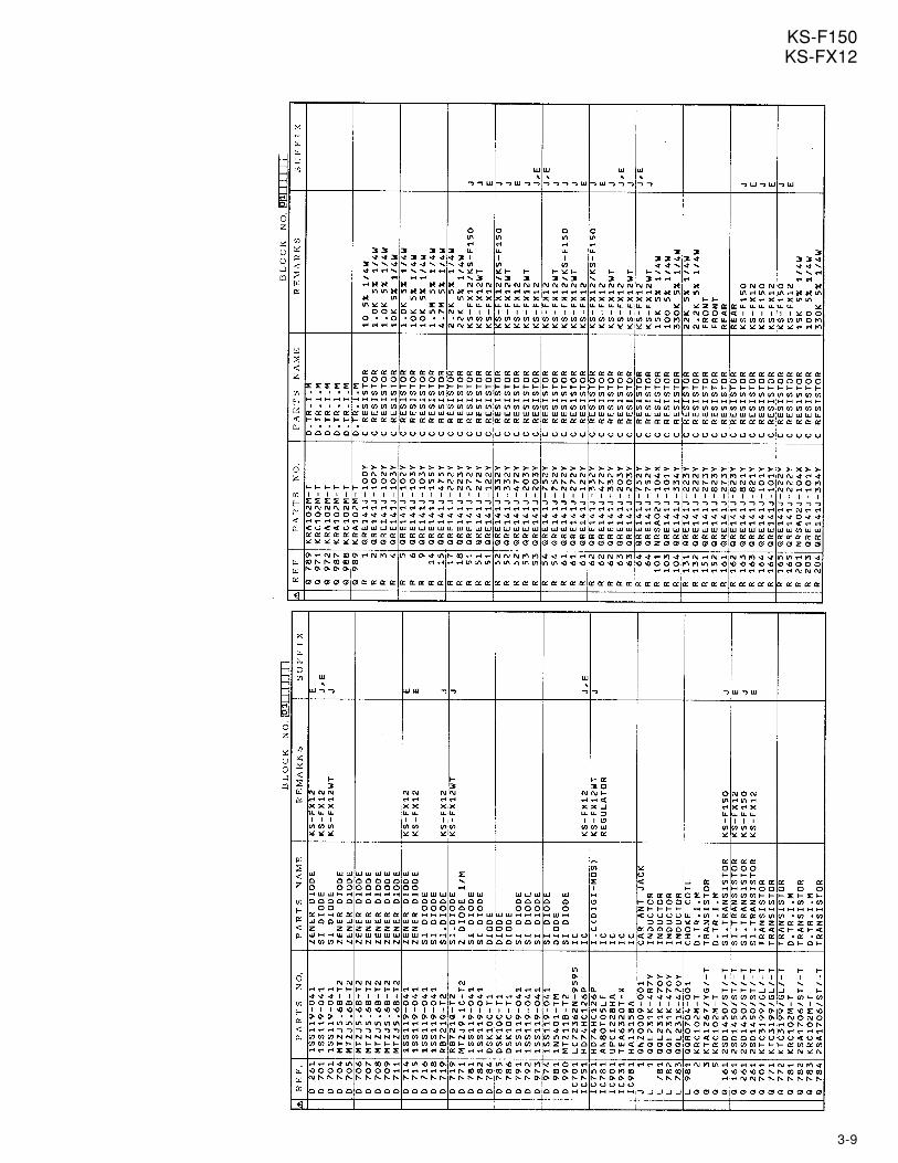
3-9
KS-F150KS-FX12
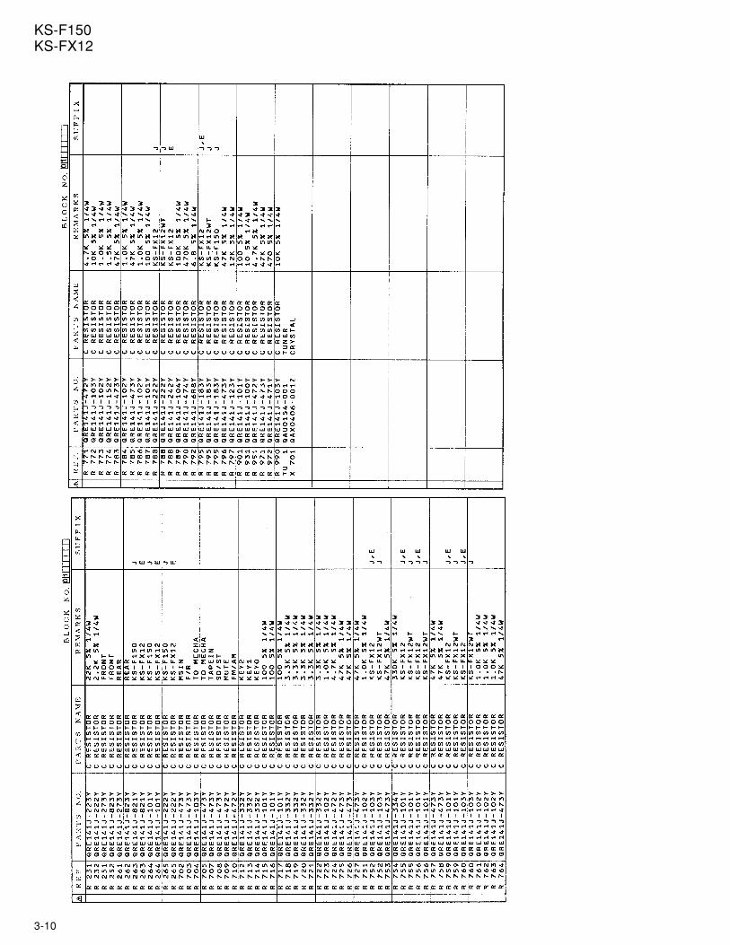
3-10
KS-F150KS-FX12
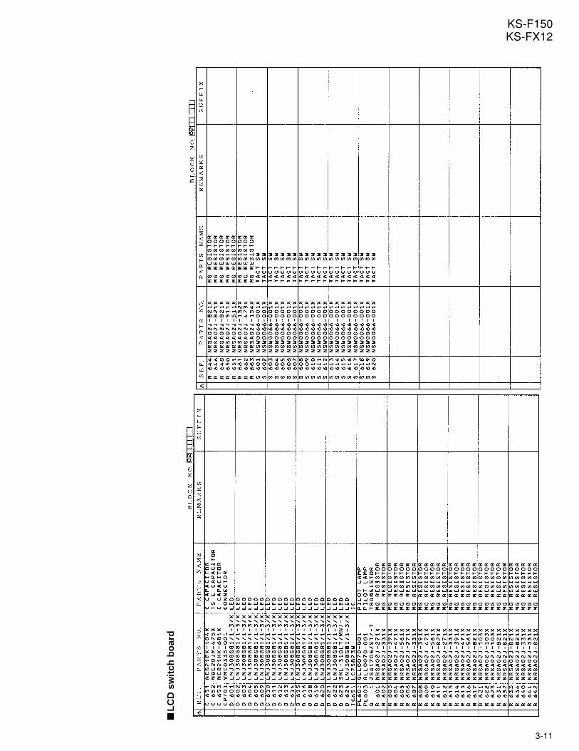
3-11
KS-F150KS-FX12
LC
D s
wit
ch b
oar
d
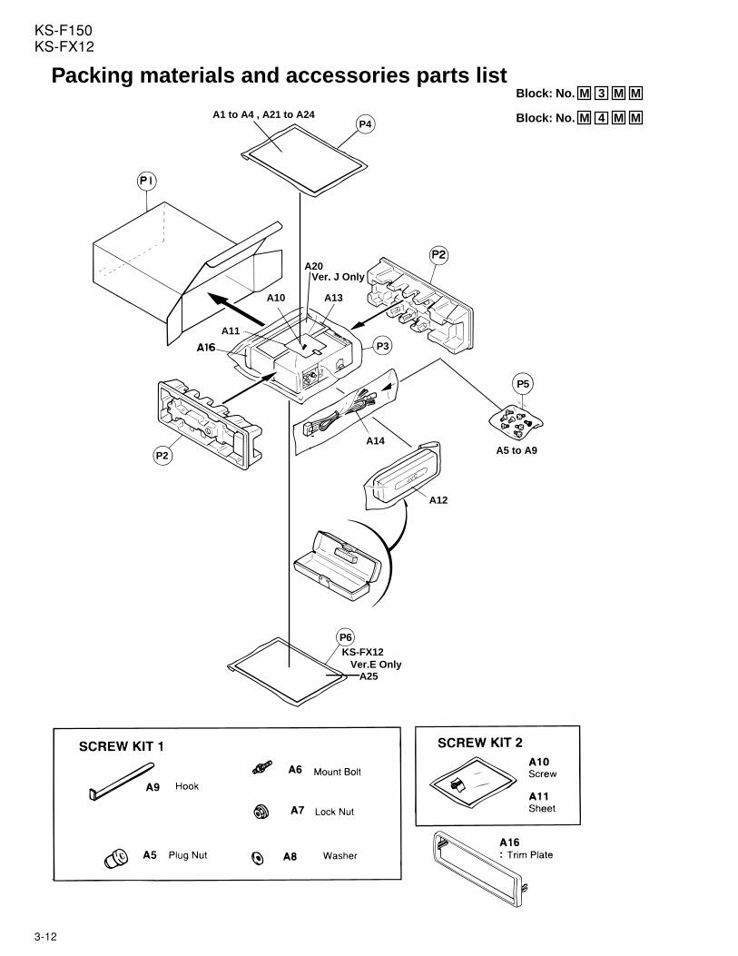
3-12
KS-F150KS-FX12
Packing materials and accessories parts list
A5 to A9
P6
A25
KS-FX12 Ver.E Only
P4
A13
A20
A10
A1 to A4 , A21 to A24
A11
A12
A14P2
P3
P5
Ver. J Only
Block: No. M 3 M M
Block: No. M 4 M M
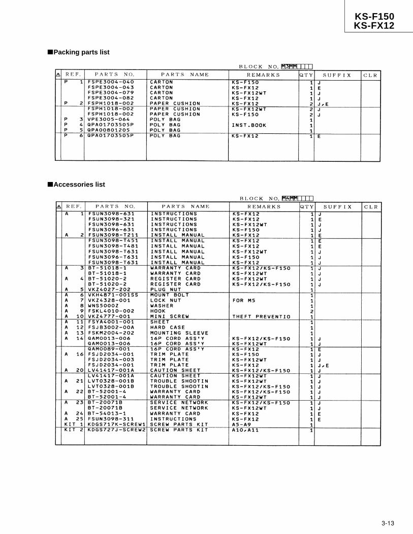
KS-F150KS-FX12
3-13
Accessories list
Packing parts list

KS-F150KS-FX12
(No.49522)
VICTOR COMPANY OF JAPAN, LIMITEDMOBILE ELECTRONICS DIVISION,10-1,1chome,Ohwatari-machi,Maebashi-city371-8543,Japan
Printed in Japan9911(M)