Embed Size (px)
Citation preview
A product of VULCAN-HART LOUISVILLE, KY 40201-0696F24682 (Rev. B, October 2007)
VC4GD WITH ROAST & HOLD SHOWN
SERVICE MANUAL
VC4G & VC6G SERIESFULL SIZE
GAS CONVECTION OVENS
MODEL MLVC4GS 126610VC4GD 126611VC4GC 136494VC6GS 126612VC6GD 126613VC6GC 136495
- NOTICE -This Manual is prepared for the use of trained Vulcan ServiceTechnicians and should not be used by those not properly qualified. Ifyou have attended a Vulcan Service School for this product, you may bequalified to perform all the procedures described in this manual.
This manual is not intended to be all encompassing. If you have notattended a Vulcan Service School for this product, you should read, inits entirety, the repair procedure you wish to perform to determine if youhave the necessary tools, instruments and skills required to perform theprocedure. Procedures for which you do not have the necessary tools,instruments and skills should be performed by a trained Vulcan ServiceTechnician.
Reproduction or other use of this Manual, without the express writtenconsent of Vulcan, is prohibited.
For additional information on Vulcan-Hart Company or to locate an authorized partsand service provider in your area, visit our website at www.vulcanhart.com.

FULL SIZE GAS CONVECTION OVENS
F24682 (Rev. B, October 2007) Page 2 of 68
TABLE OF CONTENTSGENERAL . . . . . . . . . . . . . . . . . . . . . . . . . . . . . . . . . . . . . . . . . . . . . . . . . . . . . . . . . . . . . . . . . . . . . . . . . . . . . . . . 4
Introduction . . . . . . . . . . . . . . . . . . . . . . . . . . . . . . . . . . . . . . . . . . . . . . . . . . . . . . . . . . . . . . . . . . . . . . . . . . . . 4Installation . . . . . . . . . . . . . . . . . . . . . . . . . . . . . . . . . . . . . . . . . . . . . . . . . . . . . . . . . . . . . . . . . . . . . . . . . . . . 4Operation . . . . . . . . . . . . . . . . . . . . . . . . . . . . . . . . . . . . . . . . . . . . . . . . . . . . . . . . . . . . . . . . . . . . . . . . . . . . . 4Cleaning . . . . . . . . . . . . . . . . . . . . . . . . . . . . . . . . . . . . . . . . . . . . . . . . . . . . . . . . . . . . . . . . . . . . . . . . . . . . . . 4Lubrication . . . . . . . . . . . . . . . . . . . . . . . . . . . . . . . . . . . . . . . . . . . . . . . . . . . . . . . . . . . . . . . . . . . . . . . . . . . . 4Specifications . . . . . . . . . . . . . . . . . . . . . . . . . . . . . . . . . . . . . . . . . . . . . . . . . . . . . . . . . . . . . . . . . . . . . . . . . . 4Tools . . . . . . . . . . . . . . . . . . . . . . . . . . . . . . . . . . . . . . . . . . . . . . . . . . . . . . . . . . . . . . . . . . . . . . . . . . . . . . . . . 4
REMOVAL AND REPLACEMENT OF PARTS . . . . . . . . . . . . . . . . . . . . . . . . . . . . . . . . . . . . . . . . . . . . . . . . . . . . 5Covers and Panels . . . . . . . . . . . . . . . . . . . . . . . . . . . . . . . . . . . . . . . . . . . . . . . . . . . . . . . . . . . . . . . . . . . . . . 5Control Panel Components . . . . . . . . . . . . . . . . . . . . . . . . . . . . . . . . . . . . . . . . . . . . . . . . . . . . . . . . . . . . . . . 6Component Panel Components . . . . . . . . . . . . . . . . . . . . . . . . . . . . . . . . . . . . . . . . . . . . . . . . . . . . . . . . . . . . 7Temperature Probe (VC4GD/6GD) . . . . . . . . . . . . . . . . . . . . . . . . . . . . . . . . . . . . . . . . . . . . . . . . . . . . . . . . . 8Gas Burner . . . . . . . . . . . . . . . . . . . . . . . . . . . . . . . . . . . . . . . . . . . . . . . . . . . . . . . . . . . . . . . . . . . . . . . . . . . . 8Gas Orifice . . . . . . . . . . . . . . . . . . . . . . . . . . . . . . . . . . . . . . . . . . . . . . . . . . . . . . . . . . . . . . . . . . . . . . . . . . . . 9Gas Solenoid Valve . . . . . . . . . . . . . . . . . . . . . . . . . . . . . . . . . . . . . . . . . . . . . . . . . . . . . . . . . . . . . . . . . . . . . 9Ignition Control Module . . . . . . . . . . . . . . . . . . . . . . . . . . . . . . . . . . . . . . . . . . . . . . . . . . . . . . . . . . . . . . . . . . 10Spark Igniter and Flame Sense . . . . . . . . . . . . . . . . . . . . . . . . . . . . . . . . . . . . . . . . . . . . . . . . . . . . . . . . . . . 10Blower and Motor . . . . . . . . . . . . . . . . . . . . . . . . . . . . . . . . . . . . . . . . . . . . . . . . . . . . . . . . . . . . . . . . . . . . . . 11Oven Doors and Bearings (Independent Doors) . . . . . . . . . . . . . . . . . . . . . . . . . . . . . . . . . . . . . . . . . . . . . . 12Oven Doors (Simultaneous Doors) . . . . . . . . . . . . . . . . . . . . . . . . . . . . . . . . . . . . . . . . . . . . . . . . . . . . . . . . . 13Roller Latch Assembly . . . . . . . . . . . . . . . . . . . . . . . . . . . . . . . . . . . . . . . . . . . . . . . . . . . . . . . . . . . . . . . . . . 14Door Catch Ball Assembly (Independent Doors) . . . . . . . . . . . . . . . . . . . . . . . . . . . . . . . . . . . . . . . . . . . . . . 15Door Window . . . . . . . . . . . . . . . . . . . . . . . . . . . . . . . . . . . . . . . . . . . . . . . . . . . . . . . . . . . . . . . . . . . . . . . . . 15Door Switch . . . . . . . . . . . . . . . . . . . . . . . . . . . . . . . . . . . . . . . . . . . . . . . . . . . . . . . . . . . . . . . . . . . . . . . . . . 16Mechanical KX Thermostat (VC4GS/6GS) . . . . . . . . . . . . . . . . . . . . . . . . . . . . . . . . . . . . . . . . . . . . . . . . . . . 16High Limit Thermostat . . . . . . . . . . . . . . . . . . . . . . . . . . . . . . . . . . . . . . . . . . . . . . . . . . . . . . . . . . . . . . . . . . 16Interior Lights . . . . . . . . . . . . . . . . . . . . . . . . . . . . . . . . . . . . . . . . . . . . . . . . . . . . . . . . . . . . . . . . . . . . . . . . . 17Cooling Fan . . . . . . . . . . . . . . . . . . . . . . . . . . . . . . . . . . . . . . . . . . . . . . . . . . . . . . . . . . . . . . . . . . . . . . . . . . 18
Service Procedures and Adjustments . . . . . . . . . . . . . . . . . . . . . . . . . . . . . . . . . . . . . . . . . . . . . . . . . . . . . . . . . . 19Solid State Temperature Control Calibration (VC4GD/6GD) . . . . . . . . . . . . . . . . . . . . . . . . . . . . . . . . . . . . . 19Mechanical Thermostat Calibration (VC4GS/6GS) . . . . . . . . . . . . . . . . . . . . . . . . . . . . . . . . . . . . . . . . . . . . 20Solid State Temperature Control Test (VC4GD/6GD) . . . . . . . . . . . . . . . . . . . . . . . . . . . . . . . . . . . . . . . . . . 20Temperature Probe Test (VC4GD/6GD) . . . . . . . . . . . . . . . . . . . . . . . . . . . . . . . . . . . . . . . . . . . . . . . . . . . . 21Gas Pressure Adjustment . . . . . . . . . . . . . . . . . . . . . . . . . . . . . . . . . . . . . . . . . . . . . . . . . . . . . . . . . . . . . . . . 22Verification of Spark at Ignitor . . . . . . . . . . . . . . . . . . . . . . . . . . . . . . . . . . . . . . . . . . . . . . . . . . . . . . . . . . . . 23Door Switch Adjustment . . . . . . . . . . . . . . . . . . . . . . . . . . . . . . . . . . . . . . . . . . . . . . . . . . . . . . . . . . . . . . . . . 23Blower Adjustment . . . . . . . . . . . . . . . . . . . . . . . . . . . . . . . . . . . . . . . . . . . . . . . . . . . . . . . . . . . . . . . . . . . . . 24Door Adjustment . . . . . . . . . . . . . . . . . . . . . . . . . . . . . . . . . . . . . . . . . . . . . . . . . . . . . . . . . . . . . . . . . . . . . . . 25Door Strike Adjustment (Independent Doors) . . . . . . . . . . . . . . . . . . . . . . . . . . . . . . . . . . . . . . . . . . . . . . . . . 25Door Catch Ball Adjustment (Independent Doors) . . . . . . . . . . . . . . . . . . . . . . . . . . . . . . . . . . . . . . . . . . . . . 26Door Chain Adjustment (Simultaneous Doors) . . . . . . . . . . . . . . . . . . . . . . . . . . . . . . . . . . . . . . . . . . . . . . . . 27
FULL SIZE GAS CONVECTION OVENS
F24682 (Rev. B, October 2007)Page 3 of 68
Computer Control (VC4GC/VC6GC) . . . . . . . . . . . . . . . . . . . . . . . . . . . . . . . . . . . . . . . . . . . . . . . . . . . . . . . 28Computer Control Calibration (VC4GC/VC6GC) . . . . . . . . . . . . . . . . . . . . . . . . . . . . . . . . . . . . . . . . . . . . . . 29
ELECTRICAL OPERATION . . . . . . . . . . . . . . . . . . . . . . . . . . . . . . . . . . . . . . . . . . . . . . . . . . . . . . . . . . . . . . . . . . 30Component Function . . . . . . . . . . . . . . . . . . . . . . . . . . . . . . . . . . . . . . . . . . . . . . . . . . . . . . . . . . . . . . . . . . . 30Component Location . . . . . . . . . . . . . . . . . . . . . . . . . . . . . . . . . . . . . . . . . . . . . . . . . . . . . . . . . . . . . . . . . . . 32Sequence of Operation . . . . . . . . . . . . . . . . . . . . . . . . . . . . . . . . . . . . . . . . . . . . . . . . . . . . . . . . . . . . . . . . . . 37
VC4GS, VC6GS With Roast & Hold Option (Mechanical KX Thermostat) . . . . . . . . . . . . . . . . . . . . . . . 37VC4GD, VC6GD With Roast & Hold Option (Solid State Temperature Control) . . . . . . . . . . . . . . . . . . 41Cool Down Cycle (Solid State Temperature Control) . . . . . . . . . . . . . . . . . . . . . . . . . . . . . . . . . . . . . . . 46VC4GC, VC6GC (Roast & Hold Standard on Computer Model) . . . . . . . . . . . . . . . . . . . . . . . . . . . . . . 46Cool Down Cycle (Computer Control Model) . . . . . . . . . . . . . . . . . . . . . . . . . . . . . . . . . . . . . . . . . . . . . 49
Schematics . . . . . . . . . . . . . . . . . . . . . . . . . . . . . . . . . . . . . . . . . . . . . . . . . . . . . . . . . . . . . . . . . . . . . . . . . . . 50VC4GS, VC6GS Mechanical (KX) Controls . . . . . . . . . . . . . . . . . . . . . . . . . . . . . . . . . . . . . . . . . . . . . . 50VC4GS, VC6GS Mechanical (KX) Controls, Roast & Hold Option . . . . . . . . . . . . . . . . . . . . . . . . . . . . . 51VC4GD, VC6GD Solid State Temperature Control . . . . . . . . . . . . . . . . . . . . . . . . . . . . . . . . . . . . . . . . 52VC4GD, VC6GD Solid State Temperature Control, Roast & Hold Option . . . . . . . . . . . . . . . . . . . . . . . 53VC4GC, VC6GC Computer Control (Roast & Hold Standard) . . . . . . . . . . . . . . . . . . . . . . . . . . . . . . . . 54
Wiring Diagrams . . . . . . . . . . . . . . . . . . . . . . . . . . . . . . . . . . . . . . . . . . . . . . . . . . . . . . . . . . . . . . . . . . . . . . . 56VC4GS, VC6GS Mechanical (KX) Controls . . . . . . . . . . . . . . . . . . . . . . . . . . . . . . . . . . . . . . . . . . . . . . 56VC4GS, VC6GS Mechanical (KX) Controls, Roast & Hold Option . . . . . . . . . . . . . . . . . . . . . . . . . . . . . 58VC4GD, VC6GD Solid State Temperature Control . . . . . . . . . . . . . . . . . . . . . . . . . . . . . . . . . . . . . . . . 60VC4GD, VC6GD Solid State Temperature Control, Roast & Hold Option . . . . . . . . . . . . . . . . . . . . . . . 62VC4GC, VC6GC Computer Control (Roast & Hold Standard) . . . . . . . . . . . . . . . . . . . . . . . . . . . . . . . . 64
TROUBLESHOOTING . . . . . . . . . . . . . . . . . . . . . . . . . . . . . . . . . . . . . . . . . . . . . . . . . . . . . . . . . . . . . . . . . . . . . . 66All Models . . . . . . . . . . . . . . . . . . . . . . . . . . . . . . . . . . . . . . . . . . . . . . . . . . . . . . . . . . . . . . . . . . . . . . . . . . . . 66Computer Control Models Only . . . . . . . . . . . . . . . . . . . . . . . . . . . . . . . . . . . . . . . . . . . . . . . . . . . . . . . . . . . 67
© Vulcan 2007
FULL SIZE GAS CONVECTION OVEN - GENERAL
F24682 (Rev. B, October 2007) Page 4 of 68
GENERALINTRODUCTION
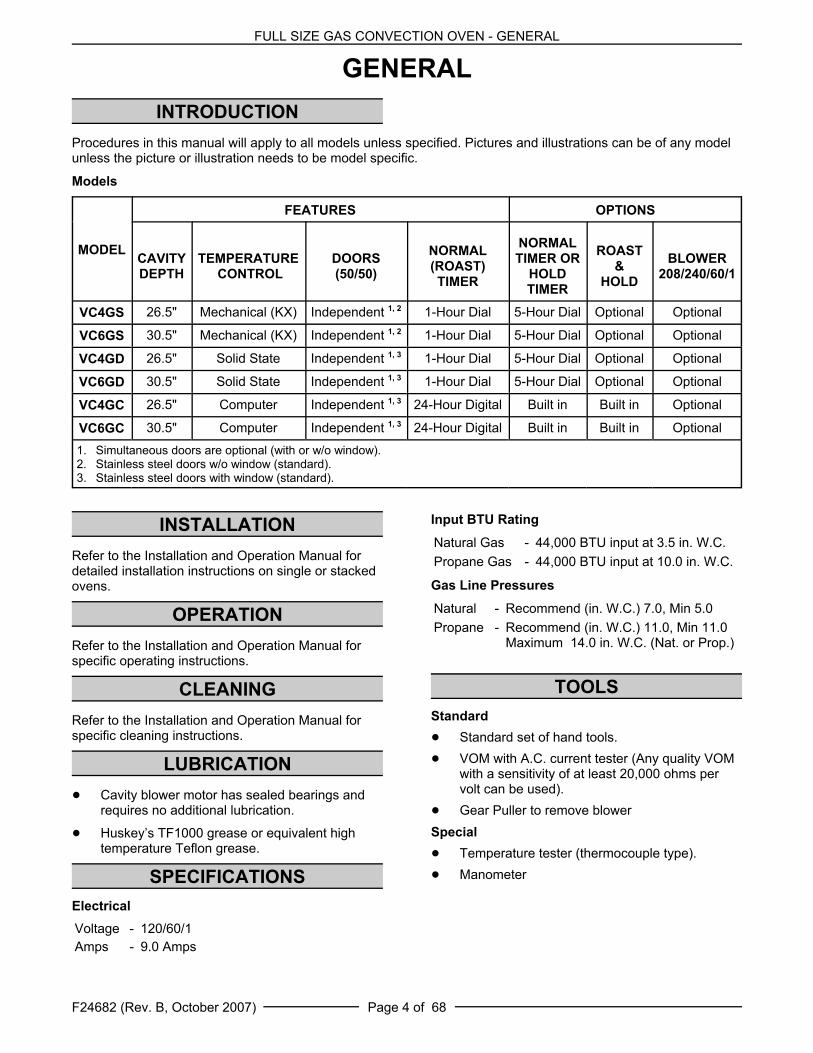
Procedures in this manual will apply to all models unless specified. Pictures and illustrations can be of any modelunless the picture or illustration needs to be model specific.
Models
MODEL
FEATURES OPTIONS
CAVITYDEPTH
TEMPERATURE CONTROL
DOORS(50/50)
NORMAL(ROAST)TIMER
NORMALTIMER OR
HOLDTIMER
ROAST&
HOLD
BLOWER208/240/60/1
VC4GS 26.5" Mechanical (KX) Independent 1, 2 1-Hour Dial 5-Hour Dial Optional Optional
VC6GS 30.5" Mechanical (KX) Independent 1, 2 1-Hour Dial 5-Hour Dial Optional Optional
VC4GD 26.5" Solid State Independent 1, 3 1-Hour Dial 5-Hour Dial Optional Optional
VC6GD 30.5" Solid State Independent 1, 3 1-Hour Dial 5-Hour Dial Optional Optional
VC4GC 26.5" Computer Independent 1, 3 24-Hour Digital Built in Built in Optional
VC6GC 30.5" Computer Independent 1, 3 24-Hour Digital Built in Built in Optional1. Simultaneous doors are optional (with or w/o window).2. Stainless steel doors w/o window (standard).3. Stainless steel doors with window (standard).
INSTALLATIONRefer to the Installation and Operation Manual fordetailed installation instructions on single or stackedovens.
OPERATIONRefer to the Installation and Operation Manual forspecific operating instructions.
CLEANINGRefer to the Installation and Operation Manual forspecific cleaning instructions.
LUBRICATION! Cavity blower motor has sealed bearings and
requires no additional lubrication.
! Huskey’s TF1000 grease or equivalent hightemperature Teflon grease.
SPECIFICATIONSElectricalVoltage - 120/60/1Amps - 9.0 Amps
Input BTU Rating
Natural Gas - 44,000 BTU input at 3.5 in. W.C.Propane Gas - 44,000 BTU input at 10.0 in. W.C.
Gas Line Pressures
Natural - Recommend (in. W.C.) 7.0, Min 5.0Propane - Recommend (in. W.C.) 11.0, Min 11.0
Maximum 14.0 in. W.C. (Nat. or Prop.)
TOOLSStandard! Standard set of hand tools.! VOM with A.C. current tester (Any quality VOM
with a sensitivity of at least 20,000 ohms pervolt can be used).
! Gear Puller to remove blowerSpecial ! Temperature tester (thermocouple type).! Manometer

FULL SIZE GAS CONVECTION OVENS - REMOVAL AND REPLACEMENT OF PARTS
F24682 (Rev. B, October 2007)Page 5 of 68
REMOVAL AND REPLACEMENT OF PARTSCOVERS AND PANELS
Top Front Cover1. The top front cover is secured with four (4)
screws, two on each side of cover. Removethese screws then remove the cover from theoven.
2. Reverse the procedure to install.
Bottom Front Cover1. The bottom front cover is secured with four (4)
screws, two on each side of cover. Removethese screws then remove the cover from theoven.
2. Reverse the procedure to install.
Control Panel1. Remove three (3) screws on the right side
which secure the control panel then pull thepanel away from the oven.
NOTE: If the oven has a mechanical (KX type)thermostat, it must be removed from the controlpanel first, before removing the control panel.
2. Disconnect the temperature probe leads fromthe solid state temperature control.
3. Unplug the wire harness connector to thecontrol panel components.
4. Reverse the procedure to install.
Right Side Panel 1. Remove the screws which secure the right side
of the top front cover, bottom front cover andcontrol panel.
2. Remove the remaining six screws securing theright side panel.
3. Pull the right side panel out at the bottom thendown to remove.
4. Reverse the procedure to install.
FULL SIZE GAS CONVECTION OVENS - REMOVAL AND REPLACEMENT OF PARTS
F24682 (Rev. B, October 2007) Page 6 of 68
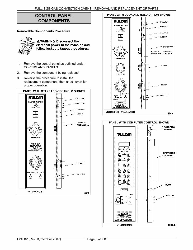
CONTROL PANELCOMPONENTS
Removable Components Procedure
1. Remove the control panel as outlined underCOVERS AND PANELS.
2. Remove the component being replaced.
3. Reverse the procedure to install thereplacement component, then check oven forproper operation.

FULL SIZE GAS CONVECTION OVENS - REMOVAL AND REPLACEMENT OF PARTS
F24682 (Rev. B, October 2007)Page 7 of 68
COMPONENT PANELCOMPONENTS
Removable Components Procedure
1. Remove the right side panel as outlined underCOVERS AND PANELS.
NOTE: If right side panel is not accessible, thiscomponent can be serviced by removing the controlpanel as outlined under COVERS AND PANELS.
2. Disconnect the wire leads to the componentbeing replaced.
3. Remove the component.
4. Reverse the procedure to install thereplacement component and check oven forproper operation.
FULL SIZE GAS CONVECTION OVENS - REMOVAL AND REPLACEMENT OF PARTS
F24682 (Rev. B, October 2007) Page 8 of 68
TEMPERATURE PROBE(VC4GD/6GD)
1. Remove the right side panel as outlined underCOVERS AND PANELS.
NOTE: If right side panel is not accessible, thiscomponent can be serviced by removing the controlpanel as outlined under COVERS AND PANELS.
2. Disconnect the probe leads from thetemperature control.
3. Remove the racks and right rack support.
4. Remove probe clips from probe.
5. Push the probe through the opening in cavityside wall and into the control panel area.
NOTE: The hole in the oven cavity wall does not lineup straight with the oven cavity outer shell, thereforethe probe must be removed at an angle.
6. Reverse the procedure to install thereplacement probe.
7. Adjust the temperature control as outlined underSOLID STATE TEMPERATURE CONTROLCALIBRATION (VC4GD/6GD) in SERVICEPROCEDURES AND ADJUSTMENTS.
GAS BURNER
Shut off the gas before servicingthe unit.1. Remove the lower front cover as outlined under
COVERS AND PANELS.
2. Disconnect the ignition cable and the flamesense lead wire.
3. Remove the bolts securing the gas manifoldand place manifold aside.
4. Remove the screws securing the burner coverthen lift out.
5. Grasp the burner and lift out.
FULL SIZE GAS CONVECTION OVENS - REMOVAL AND REPLACEMENT OF PARTS
F24682 (Rev. B, October 2007)Page 9 of 68
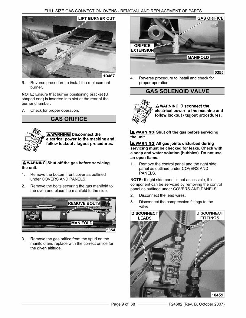
6. Reverse procedure to install the replacementburner.
NOTE: Ensure that burner positioning bracket (Ushaped end) is inserted into slot at the rear of theburner chamber.
7. Check for proper operation.
GAS ORIFICE
Shut off the gas before servicingthe unit.1. Remove the bottom front cover as outlined
under COVERS AND PANELS.
2. Remove the bolts securing the gas manifold tothe oven and place the manifold to the side.
3. Remove the gas orifice from the spud on themanifold and replace with the correct orifice forthe given altitude.
4. Reverse procedure to install and check forproper operation.
GAS SOLENOID VALVE
Shut off the gas before servicingthe unit.
All gas joints disturbed duringservicing must be checked for leaks. Check witha soap and water solution (bubbles). Do not usean open flame.1. Remove the control panel and the right side
panel as outlined under COVERS ANDPANELS.
NOTE: If right side panel is not accessible, thiscomponent can be serviced by removing the controlpanel as outlined under COVERS AND PANELS.2. Disconnect the lead wires.3. Disconnect the compression fittings to the
valve.
FULL SIZE GAS CONVECTION OVENS - REMOVAL AND REPLACEMENT OF PARTS
F24682 (Rev. B, October 2007) Page 10 of 68
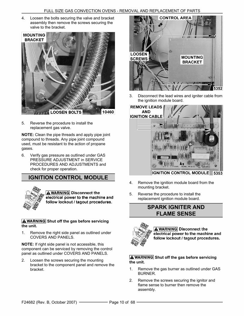
4. Loosen the bolts securing the valve and bracketassembly then remove the screws securing thevalve to the bracket.
5. Reverse the procedure to install thereplacement gas valve.
NOTE: Clean the pipe threads and apply pipe jointcompound to threads. Any pipe joint compoundused, must be resistant to the action of propanegases.
6. Verify gas pressure as outlined under GASPRESSURE ADJUSTMENT in SERVICEPROCEDURES AND ADJUSTMENTS andcheck for proper operation.
IGNITION CONTROL MODULE
Shut off the gas before servicingthe unit.1. Remove the right side panel as outlined under
COVERS AND PANELS.
NOTE: If right side panel is not accessible, thiscomponent can be serviced by removing the controlpanel as outlined under COVERS AND PANELS.
2. Loosen the screws securing the mountingbracket to the component panel and remove thebracket.
3. Disconnect the lead wires and igniter cable fromthe ignition module board.
4. Remove the ignition module board from themounting bracket.
5. Reverse the procedure to install thereplacement ignition module board.
SPARK IGNITER ANDFLAME SENSE
Shut off the gas before servicingthe unit.1. Remove the gas burner as outlined under GAS
BURNER.
2. Remove the screws securing the ignitor andflame sense to burner then remove theassembly.

FULL SIZE GAS CONVECTION OVENS - REMOVAL AND REPLACEMENT OF PARTS
F24682 (Rev. B, October 2007)Page 11 of 68
3. Reverse the procedure to install the assemblyand check for proper operation.
NOTE: Check to ensure the spark gap distance isapproximately 1/8". If the gap appears to beexcessive or poor sparking is occurring then adjust.
BLOWER AND MOTOR
Shut off the gas before servicingthe unit.1. Take out the racks and rack supports.
2. Remove screws securing the SNORKEL andremove the snorkel.
3. Remove screws securing baffle panel andremove the panel.
4. If replacing:
A. Blower Only - Loosen set screws on blowerhub and using a bearing puller, removeblower from motor shaft.
1) Reverse procedure to install andadjust blower position as outlinedunder BLOWER ADJUSTMENT inSERVICE PROCEDURES ANDADJUSTMENTS.
B. Motor - perform step 4A and continueprocedure.
5. Remove the screws securing the air baffle tothe rear wall at the lower right hand corner.
FULL SIZE GAS CONVECTION OVENS - REMOVAL AND REPLACEMENT OF PARTS
F24682 (Rev. B, October 2007) Page 12 of 68
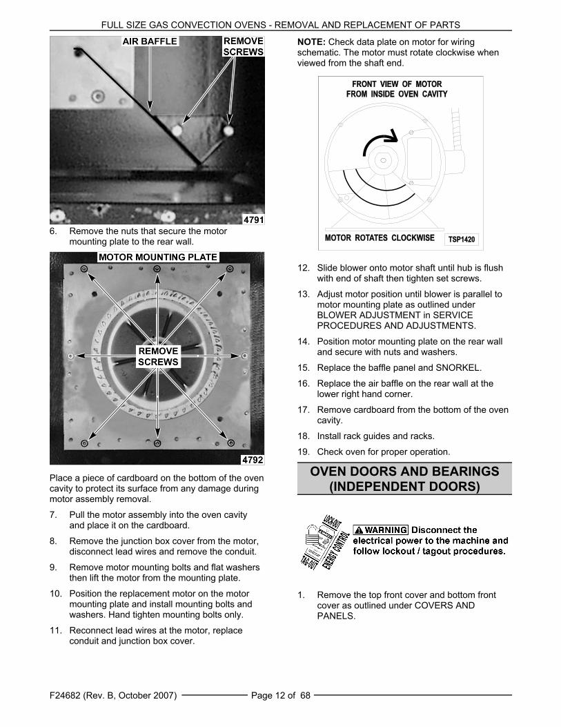
6. Remove the nuts that secure the motormounting plate to the rear wall.
Place a piece of cardboard on the bottom of the ovencavity to protect its surface from any damage duringmotor assembly removal.
7. Pull the motor assembly into the oven cavityand place it on the cardboard.
8. Remove the junction box cover from the motor,disconnect lead wires and remove the conduit.
9. Remove motor mounting bolts and flat washersthen lift the motor from the mounting plate.
10. Position the replacement motor on the motormounting plate and install mounting bolts andwashers. Hand tighten mounting bolts only.
11. Reconnect lead wires at the motor, replaceconduit and junction box cover.
NOTE: Check data plate on motor for wiringschematic. The motor must rotate clockwise whenviewed from the shaft end.
12. Slide blower onto motor shaft until hub is flushwith end of shaft then tighten set screws.
13. Adjust motor position until blower is parallel tomotor mounting plate as outlined underBLOWER ADJUSTMENT in SERVICEPROCEDURES AND ADJUSTMENTS.
14. Position motor mounting plate on the rear walland secure with nuts and washers.
15. Replace the baffle panel and SNORKEL.
16. Replace the air baffle on the rear wall at thelower right hand corner.
17. Remove cardboard from the bottom of the ovencavity.
18. Install rack guides and racks.
19. Check oven for proper operation.
OVEN DOORS AND BEARINGS(INDEPENDENT DOORS)
1. Remove the top front cover and bottom frontcover as outlined under COVERS ANDPANELS.
FULL SIZE GAS CONVECTION OVENS - REMOVAL AND REPLACEMENT OF PARTS
F24682 (Rev. B, October 2007)Page 13 of 68
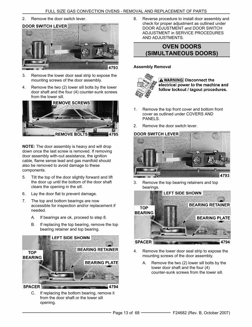
2. Remove the door switch lever.
3. Remove the lower door seal strip to expose themounting screws of the door assembly.
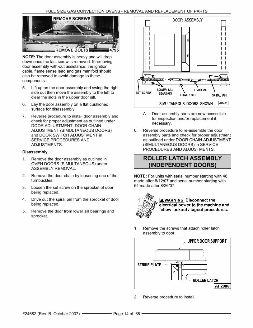
4. Remove the two (2) lower sill bolts by the lowerdoor shaft and the four (4) counter-sunk screwsfrom the lower sill.
NOTE: The door assembly is heavy and will dropdown once the last screw is removed. If removingdoor assembly with-out assistance, the ignitioncable, flame sense lead and gas manifold shouldalso be removed to avoid damage to thesecomponents.
5. Tilt the top of the door slightly forward and liftthe door up until the bottom of the door shaftclears the opening in the sill.
6. Lay the door flat to prevent damage.
7. The top and bottom bearings are nowaccessible for inspection and/or replacement ifneeded.
A. If bearings are ok, proceed to step 8.
B. If replacing the top bearing, remove the topbearing retainer and top bearing.
C. If replacing the bottom bearing, remove itfrom the door shaft or the lower sillopening.
8. Reverse procedure to install door assembly andcheck for proper adjustment as outlined underDOOR ADJUSTMENT and DOOR SWITCHADJUSTMENT in SERVICE PROCEDURESAND ADJUSTMENTS.
OVEN DOORS(SIMULTANEOUS DOORS)
Assembly Removal
1. Remove the top front cover and bottom frontcover as outlined under COVERS ANDPANELS.
2. Remove the door switch lever.
3. Remove the top bearing retainers and topbearings.
4. Remove the lower door seal strip to expose themounting screws of the door assembly.
A. Remove the two (2) lower sill bolts by thelower door shaft and the four (4)counter-sunk screws from the lower sill.
FULL SIZE GAS CONVECTION OVENS - REMOVAL AND REPLACEMENT OF PARTS
F24682 (Rev. B, October 2007) Page 14 of 68
NOTE: The door assembly is heavy and will dropdown once the last screw is removed. If removingdoor assembly with-out assistance, the ignitioncable, flame sense lead and gas manifold shouldalso be removed to avoid damage to thesecomponents.
5. Lift up on the door assembly and swing the rightside out then move the assembly to the left toclear the slots in the upper door sill.
6. Lay the door assembly on a flat cushionedsurface for disassembly.
7. Reverse procedure to install door assembly andcheck for proper adjustment as outlined underDOOR ADJUSTMENT, DOOR CHAINADJUSTMENT (SIMULTANEOUS DOORS)and DOOR SWITCH ADJUSTMENT inSERVICE PROCEDURES ANDADJUSTMENTS.
Disassembly1. Remove the door assembly as outlined in
OVEN DOORS (SIMULTANEOUS) underASSEMBLY REMOVAL.
2. Remove the door chain by loosening one of theturnbuckles.
3. Loosen the set screw on the sprocket of doorbeing replaced.
4. Drive out the spiral pin from the sprocket of doorbeing replaced.
5. Remove the door from lower sill bearings andsprocket.
A. Door assembly parts are now accessiblefor inspection and/or replacement ifnecessary.
6. Reverse procedure to re-assemble the doorassembly parts and check for proper adjustmentas outlined under DOOR CHAIN ADJUSTMENT(SIMULTANEOUS DOORS) in SERVICEPROCEDURES AND ADJUSTMENTS.
ROLLER LATCH ASSEMBLY(INDEPENDENT DOORS)
NOTE: For units with serial number starting with 48made after 8/12/07 and serial number starting with54 made after 8/26/07.
1. Remove the screws that attach roller latchassembly to door.
2. Reverse procedure to install.

FULL SIZE GAS CONVECTION OVENS - REMOVAL AND REPLACEMENT OF PARTS
F24682 (Rev. B, October 2007)Page 15 of 68
DOOR CATCH BALL ASSEMBLY(INDEPENDENT DOORS)
NOTE: For units with serial number starting with 48made before 8/13/07 and serial number starting with54 made before 8/27/07.
1. Remove the top front cover as outlined underCOVERS AND PANELS.
2. Remove the screws that secure the door catchassembly.
3. Reverse procedure to install.
4. Adjust the ball catch as outlined under DOORCATCH BALL ADJUSTMENT (INDEPENDENTDOORS) in SERVICE PROCEDURES ANDADJUSTMENTS.
DOOR WINDOW
1. Remove the screws at the top and bottom ofdoor.
2. Independent doors:
A. Remove the door handle then remove theouter door panel.
B. Lift out the inner door panel and windowassembly.
NOTE: Left door only - remove door seal fromthe inside edge of the door.
3. Simultaneous doors:
A. If replacing window on the left door,remove the handle from the front of thedoor then remove door seal from the insideedge of the door.
1) Lift out the inner door panel andwindow assembly.
2) If replacing window on the right door,remove the screws along the insideedge (if applicable) of the door thenremove the inner door panel andwindow assembly.
4. Remove the screws securing the window TABSto the door bracket and lift the window assemblyout from the door frame.

FULL SIZE GAS CONVECTION OVENS - REMOVAL AND REPLACEMENT OF PARTS
F24682 (Rev. B, October 2007) Page 16 of 68
5. Reverse procedure to install the replacementwindow.
DOOR SWITCH
1. Remove the top front cover as outlined underCOVERS AND PANELS.
2. Disconnect the lead wires to the door switch.
3. Remove the switch.
4. Reverse procedure to install the replacementswitch and check for proper adjustment asoutlined under DOOR SWITCH ADJUSTMENTin SERVICE PROCEDURES ANDADJUSTMENTS.
MECHANICAL KX THERMOSTAT (VC4GS/6GS)
1. Remove the racks and right rack support.
2. Remove the thermostat knob and mountingscrews from the control panel and then removethe control panel.
3. Remove the probe guard from the oven cavitywall.
NOTE: When installing, the probe should not extendbeyond the probe guard.
4. Remove the thermostat bulb from the ovencavity by pushing it through the oven wall andinto the control panel area.
NOTE: The hole in the oven cavity wall does not lineup straight with the oven cavity outer shell, thereforethe probe must be removed at an angle.
5. Reverse the procedure to install.
6. Adjust the thermostat as outlined underMECHANICAL THERMOSTAT CALIBRATION(VC4GS/6GS) in SERVICE PROCEDURESAND ADJUSTMENTS.
HIGH LIMIT THERMOSTAT
1. Take out racks from the oven.
2. Remove the high limit thermostatcover/mounting plate from inside the ovencavity at the top.

FULL SIZE GAS CONVECTION OVENS - REMOVAL AND REPLACEMENT OF PARTS
F24682 (Rev. B, October 2007)Page 17 of 68
3. Disconnect lead wires from high limit thermostatthen remove high limit thermostat fromcover/mounting plate.
NOTE: Remove the old RTV from the cover andmating surfaces inside the oven cavity and applynew RTV before installing.
4. Reverse procedure to install.
INTERIOR LIGHTS
Lamp1. Remove the racks.
2. Unscrew the glass lens for the light beingreplaced then unscrew the bulb.
3. Replace bulb then reverse the procedure toinstall.
Lamp Assembly
1. Remove the lens and bulb.
2. Remove the springs from the retaining tabs (2places) on the socket.
3. Depress the retaining tabs and pull the socketout from the oven, far enough to disconnect thelead wires.
4. Remove the socket from the oven.
5. Attach the lead wires to the replacement socket.
6. Insert the socket into the hole in the oven andpush until the socket is held in place by theretaining tabs.
7. Install the light bulb and lens.
8. Check for proper operation.
FULL SIZE GAS CONVECTION OVENS - REMOVAL AND REPLACEMENT OF PARTS
F24682 (Rev. B, October 2007) Page 18 of 68
COOLING FAN
1. Remove the right side panel as outlined underCOVERS AND PANELS.
NOTE: If right side panel is not accessible, thiscomponent can be serviced by removing the controlpanel as outlined under COVERS AND PANELS.
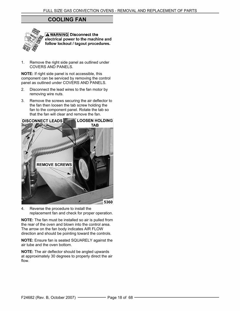
2. Disconnect the lead wires to the fan motor byremoving wire nuts.
3. Remove the screws securing the air deflector tothe fan then loosen the tab screw holding thefan to the component panel. Rotate the tab sothat the fan will clear and remove the fan.
4. Reverse the procedure to install thereplacement fan and check for proper operation.
NOTE: The fan must be installed so air is pulled fromthe rear of the oven and blown into the control area.The arrow on the fan body indicates AIR FLOWdirection and should be pointing toward the controls.
NOTE: Ensure fan is seated SQUARELY against theair tube and the oven bottom.
NOTE: The air deflector should be angled upwardsat approximately 30 degrees to properly direct the airflow.
FULL SIZE GAS CONVECTION OVENS - SERVICE PROCEDURES AND ADJUSTMENTS
F24682 (Rev. B, October 2007)Page 19 of 68
SERVICE PROCEDURES AND ADJUSTMENTS Certain procedures in this section require electrical test or measurements while power is
applied to the machine. Exercise extreme caution at all times. If test points are not easily accessible,disconnect power and follow lockout / tagout procedures, attach test equipment and reapply power totest.
SOLID STATE TEMPERATURECONTROL CALIBRATION
(VC4GD/6GD)1. Place a thermocouple in the geometric center of
the oven cavity.
2. Set the ON-OFF-COOL DOWN switch to ON.
3. Set the temperature control dial to 350°F.
4. Allow the oven temperature to stabilize(normally 3 cycles).
5. Record the temperature at which the Heat lampgoes OFF and comes ON for at least twocomplete heating cycles.
6. Calculate the differential by subtracting thetemperature indicated when the lamp goes outfrom the temperature indicated when the lampcomes on.
A. The differential calculated should be lessthan 20 °F.
1) If the differential is less than 20 °F, thetemperature control circuit isfunctioning properly.
a. Proceed to step 7.
2) If the differential is more than 20 °F:
a. Check the temperature probe asoutlined under TEMPERATUREPROBE TEST (VC4GD/6GD).
b. If the probe is functioningproperly then temperature controlis malfunctioning.
a) Install a replacementtemperature control andcheck calibration.
7. Calculate the average temperature by addingthe temperature indicated when the lamp goesout to the temperature indicated when the lampcomes on and dividing this answer by 2.
A. If the average temperature is less than 10 °F from the dial setting, the thermostatis properly calibrated.
B. If the average temperature is more than 10 °F from the dial setting, the thermostatcalibration must be adjusted.
1) Loosen the temperature control knobset screw and remove the knob fromthe stem.
2) Loosen temperature control mountingscrews only enough to rotate thecontrol.
a. Place thumb and forefinger onthe head of the mounting screws,apply pressure and slightly rotatethe screw heads (body of control)in the slot. Rotate clockwise toincrease temperature andcounterclockwise to decrease.
b. Center the stem in the openingand re-tighten the temperaturecontrol mounting screws.
c. Replace knob and re-tighten setscrew .
d. Rotate the knob to the lowesttemperature setting then back to350°F.
e. Repeat the average temperaturecalculation in step 7.
NOTE: Allow the oven to cycle atleast two times betweenadjustments before performingthe calculation.
a) If the average temperaturestill differs more than 10 °Ffrom the dial setting, adjustthe thermostat calibrationuntil the averagetemperature is withintolerance.
C. If the above adjustment cannot beobtained, replace the temperature controland check calibration.

FULL SIZE GAS CONVECTION OVENS - SERVICE PROCEDURES AND ADJUSTMENTS
F24682 (Rev. B, October 2007) Page 20 of 68
MECHANICAL THERMOSTATCALIBRATION (VC4GS/6GS)
1. Place a thermocouple in the geometric center ofthe oven cavity.
2. Set the ON-OFF-COOL DOWN switch to ON.
3. Set the thermostat dial to 350°F.
4. Allow the oven temperature to stabilize(normally 3 cycles).
5. Record the temperature when the thermostatcycles OFF and ON for at least three completecycles.
6. Calculate the differential by subtracting thetemperature indicated when heat lamp goes outfrom temperature indicated when heat lampcomes on.
A. The differential calculated should be lessthan 30EF.
1) If the differential is less than 30° F, thethermostat is functioning properly.
a. Proceed to step 7.
2) If the differential is more than 30EF,the thermostat is malfunctioning.
a. Install a replacement thermostatand check calibration.
7. Calculate the average temperature by addingthe temperature indicated when the heat lampgoes out to the temperature indicated when theheat lamp comes on and dividing this answer by2.
A. If the average temperature is less than15EF from the dial setting, the thermostat isproperly calibrated.
B. If the average temperature is more than15EF of the dial setting, the thermostatcalibration must be adjusted.
1) Remove the thermostat knob.
2) Hold the thermostat shaft and turn theinner set screw clockwise to decreasetemperature or counterclockwise toincrease temperature (1/4 turn =35EF).
8. Replace the knob and repeat step 7 until theaverage temperature is within tolerance.
NOTE: Allow the oven to cycle at least two timesbetween adjustments before performing thecalculation.
9. If the above adjustment can not be obtained,install a replacement thermostat and checkcalibration.
SOLID STATE TEMPERATURECONTROL TEST (VC4GD/6GD)
1. Remove the right side panel as outlined underCOVERS AND PANELS in REMOVAL ANDREPLACEMENT OF PARTS.
NOTE: If right side panel is not accessible, thiscomponent can be serviced by removing the controlpanel as outlined under COVERS AND PANELS.
2. Place a thermocouple in the geometric center ofthe oven cavity.
NOTE: Oven temperature must be below 450°.
NOTE: If oven is equipped with the Roast and Holdoption, turn it to Normal ROAST (normal cooking)before continuing.
3. Set the temperature control to the maximumsetting.

FULL SIZE GAS CONVECTION OVENS - SERVICE PROCEDURES AND ADJUSTMENTS
F24682 (Rev. B, October 2007)Page 21 of 68
4. Check machine data plate for correct voltage tooven. Refer to diagram below for properterminal locations and voltages before checkingthe control. Use the correct terminals for thecorresponding voltage.
5. Turn the ON-OFF-COOL DOWN switch to ON.
6. Check for proper voltage across terminals 8 & 9(120VAC) or terminals 8 & 10 (208-240VAC) forpower to the control.A. If correct, proceed to step 7.B. If incorrect, problem is not with the
temperature control (See troubleshootingsection).
7. Check relay voltages on the board:A. For 120VAC controls - check across
terminals 7 & 9 for input to the internalrelay and 6 & 9 for output from the internalrelay.
B. For 208-240VAC controls - check acrossterminals 7 & 10 for input to the internalrelay and 6 & 10 for output from theinternal relay.1) If input voltage to the internal relay is
correct, proceed to step 8. If inputvoltage to the internal relay is notpresent, problem is not with thetemperature control (Seetroubleshooting section).
2) If output voltage from the internalrelay is correct proceed to step 8. Ifoutput voltage from the internal relayis not correct, check temperatureprobe as outlined underTEMPERATURE PROBE TEST(VC4GD/6GD).
8. Set the temperature control to the minimumsetting.
NOTE: Oven temperature must be above 300°F.9. Check for zero (0) volts AC across terminals 6 &
9 (120VAC) or 6 & 10 (208-240VAC) for nooutput from the internal relay.
A. If correct, temperature control isfunctioning properly.
B. If incorrect, check temperature probe asoutlined under TEMPERATURE PROBETEST (VC4GD/6GD).1) If temperature probe is ok, replace the
temperature control and checkcalibration as outlined under SOLIDSTATE TEMPERATURE CONTROLCALIBRATION (VC4GD/6GD).
TEMPERATURE PROBE TEST(VC4GD/6GD)
NOTE: The temperature probe used in conjunctionwith the Solid State Temperature control is an RTD(resistance temperature detector) of the Thermistortype. As temperature increases the resistance valuedecreases.
1. Remove the right side panel as outlined underCOVERS AND PANELS in REMOVAL ANDREPLACEMENT OF PARTS.
NOTE: If right side panel is not accessible, thiscomponent can be serviced by removing the controlpanel as outlined under COVERS AND PANELS.
2. Place a shielded thermocouple in the geometriccenter of the oven cavity and determine thetemperature in the oven cavity.
3. Remove the probe lead wires from the solidstate temperature control.
4. Test the probe with an ohmmeter.
A. If the measured resistance values areinside the given tolerance then the probe isfunctioning properly.
B. If the measured resistance values areoutside the given tolerance then replacethe probe and retest.
1) Check oven for proper operation.
FULL SIZE GAS CONVECTION OVENS - SERVICE PROCEDURES AND ADJUSTMENTS
F24682 (Rev. B, October 2007) Page 22 of 68
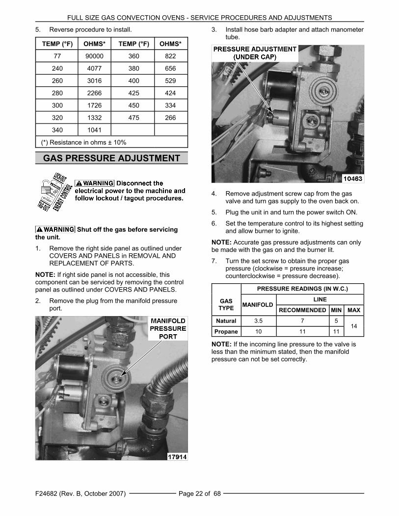
5. Reverse procedure to install.
TEMP (°F) OHMS* TEMP (°F) OHMS*
77 90000 360 822
240 4077 380 656
260 3016 400 529
280 2266 425 424
300 1726 450 334
320 1332 475 266
340 1041
(*) Resistance in ohms ± 10%
GAS PRESSURE ADJUSTMENT
Shut off the gas before servicingthe unit.1. Remove the right side panel as outlined under
COVERS AND PANELS in REMOVAL ANDREPLACEMENT OF PARTS.
NOTE: If right side panel is not accessible, thiscomponent can be serviced by removing the controlpanel as outlined under COVERS AND PANELS.
2. Remove the plug from the manifold pressureport.
3. Install hose barb adapter and attach manometertube.
4. Remove adjustment screw cap from the gasvalve and turn gas supply to the oven back on.
5. Plug the unit in and turn the power switch ON.
6. Set the temperature control to its highest settingand allow burner to ignite.
NOTE: Accurate gas pressure adjustments can onlybe made with the gas on and the burner lit.
7. Turn the set screw to obtain the proper gaspressure (clockwise = pressure increase;counterclockwise = pressure decrease).
GASTYPE
PRESSURE READINGS (IN W.C.)
MANIFOLD LINE
RECOMMENDED MIN MAX
Natural 3.5 7 514
Propane 10 11 11
NOTE: If the incoming line pressure to the valve isless than the minimum stated, then the manifoldpressure can not be set correctly.
FULL SIZE GAS CONVECTION OVENS - SERVICE PROCEDURES AND ADJUSTMENTS
F24682 (Rev. B, October 2007)Page 23 of 68
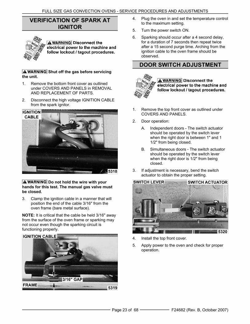
VERIFICATION OF SPARK ATIGNITOR
Shut off the gas before servicingthe unit.1. Remove the bottom front cover as outlined
under COVERS AND PANELS in REMOVALAND REPLACEMENT OF PARTS.
2. Disconnect the high voltage IGNITION CABLEfrom the spark ignitor.
Do not hold the wire with yourhands for this test. The manual gas valve mustbe closed.3. Clamp the ignition cable in a manner that will
position the end of the cable 3/16" from theoven frame (bare metal surface).
NOTE: It is critical that the cable be held 3/16" awayfrom the surface of the oven frame or sparking maynot occur even though the sparking circuit isfunctioning properly.
4. Plug the oven in and set the temperature controlto the maximum setting.
5. Turn the power switch ON.
6. Sparking should occur after a 4 second delay,for a duration of 7 seconds then repeat twiceafter a 15 second purge time. Arching from theignition cable to the oven frame should beobserved.
DOOR SWITCH ADJUSTMENT
1. Remove the top front cover as outlined underCOVERS AND PANELS.
2. Door operation:
A. Independent doors - The switch actuatorshould be operated by the switch leverwhen the right door is between 1" and 11/2" from being closed.
B. Simultaneous doors - The switch actuatorshould be operated by the switch leverwhen the right door is 1/2" from beingclosed.
3. If adjustment is necessary, bend the switchactuator to obtain the proper setting.
4. Install the top front cover.
5. Apply power to the oven and check for properoperation.
FULL SIZE GAS CONVECTION OVENS - SERVICE PROCEDURES AND ADJUSTMENTS
F24682 (Rev. B, October 2007) Page 24 of 68
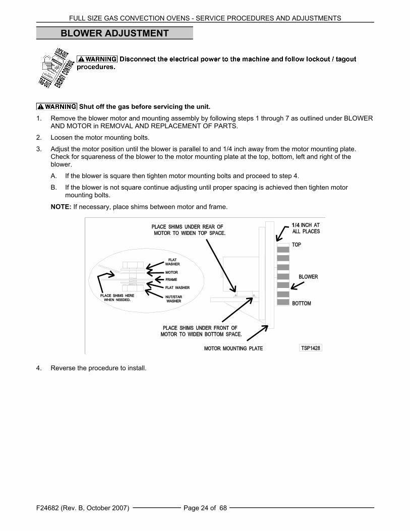
BLOWER ADJUSTMENT
Shut off the gas before servicing the unit.
1. Remove the blower motor and mounting assembly by following steps 1 through 7 as outlined under BLOWERAND MOTOR in REMOVAL AND REPLACEMENT OF PARTS.
2. Loosen the motor mounting bolts.
3. Adjust the motor position until the blower is parallel to and 1/4 inch away from the motor mounting plate.Check for squareness of the blower to the motor mounting plate at the top, bottom, left and right of theblower.
A. If the blower is square then tighten motor mounting bolts and proceed to step 4.
B. If the blower is not square continue adjusting until proper spacing is achieved then tighten motormounting bolts.
NOTE: If necessary, place shims between motor and frame.
4. Reverse the procedure to install.
FULL SIZE GAS CONVECTION OVENS - SERVICE PROCEDURES AND ADJUSTMENTS
F24682 (Rev. B, October 2007)Page 25 of 68
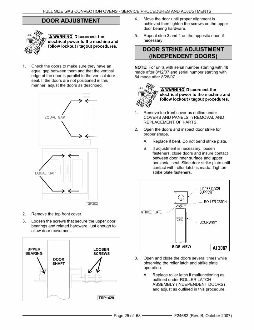
DOOR ADJUSTMENT
1. Check the doors to make sure they have anequal gap between them and that the verticaledge of the door is parallel to the vertical doorseal. If the doors are not positioned in thismanner, adjust the doors as described.
2. Remove the top front cover.
3. Loosen the screws that secure the upper doorbearings and related hardware, just enough toallow door movement.
4. Move the door until proper alignment isachieved then tighten the screws on the upperdoor bearing hardware.
5. Repeat step 3 and 4 on the opposite door, ifnecessary.
DOOR STRIKE ADJUSTMENT(INDEPENDENT DOORS)
NOTE: For units with serial number starting with 48made after 8/12/07 and serial number starting with54 made after 8/26/07.
1. Remove top front cover as outline underCOVERS AND PANELS in REMOVAL ANDREPLACEMENT OF PARTS.
2. Open the doors and inspect door strike forproper shape.
A. Replace if bent. Do not bend strike plate.
B. If adjustment is necessary, loosenfasteners, close doors and insure contactbetween door inner surface and upperhorizontal seal. Slide door strike plate untilcontact with roller latch is made. Tightenstrike plate fasteners.
3. Open and close the doors several times whileobserving the roller latch and strike plateoperation.
A. Replace roller latch if malfunctioning asoutlined under ROLLER LATCHASSEMBLY (INDEPENDENT DOORS)and adjust as outlined in this procedure.

FULL SIZE GAS CONVECTION OVENS - SERVICE PROCEDURES AND ADJUSTMENTS
F24682 (Rev. B, October 2007) Page 26 of 68
4. Each oven door should open with a force of 8 to25 pounds when pulled at the handle. Theadjustments must allow the doors to remainclosed during normal operation and allowopening without exertion by the user.
DOOR CATCH BALLADJUSTMENT
(INDEPENDENT DOORS)
NOTE: For units with serial number starting with 48made before 8/13/07 and serial number starting with54 made before 8/27/07.
1. Remove top front cover as outline underCOVERS AND PANELS in REMOVAL ANDREPLACEMENT OF PARTS.
2. Open the doors and inspect door strike forproper shape.
A. Replace if bent and adjust as outlined inthis procedure.
3. Open and close the doors several times whileobserving the catch ball operation.
A. Replace if malfunctioning and adjust asoutlined in this procedure.
NOTE: Shims may be required under thedoor strike, before the proper door tensionadjustment can be set.
4. Apply lubricant at the top of the door catchassembly to lubricate the internal spring. SeeLUBRICATION under GENERAL.
5. Close the doors and check them for properalignment.
A. Doors should be centered and parallel atthe top and bottom in the oven cavityopening as outlined under DOORADJUSTMENT.
6. Open right side door and view the left side catchball and door strike position. Ensure catch ballis resting upon the angular surface of doorstrike. Repeat on opposite door.
NOTE: If catch ball is striking the flat surface on doorstrike, shims will be required under the door catchassembly.
NOTE: The catch ball should make contact near thecenter of door strike.
A. If adjustment is necessary, loosenmounting screws then slide door strikefrom front to back until roller ball rests uponthe angular surface of the door strike.Tighten screws and check operation.
B. If proper adjustment cannot be achieved,add shims beneath the door strike. Repeatstep 6. DO NOT BEND THE DOORSTRIKE.
7. Each oven door should open with a force of 8 to25 pounds when pulled at the handle. Theadjustment must allow the doors to remainclosed during normal operation and allowopening without exertion by the user.
NOTE: The amount of tension on catch balldetermines the opening force of door.
FULL SIZE GAS CONVECTION OVENS - SERVICE PROCEDURES AND ADJUSTMENTS
F24682 (Rev. B, October 2007)Page 27 of 68
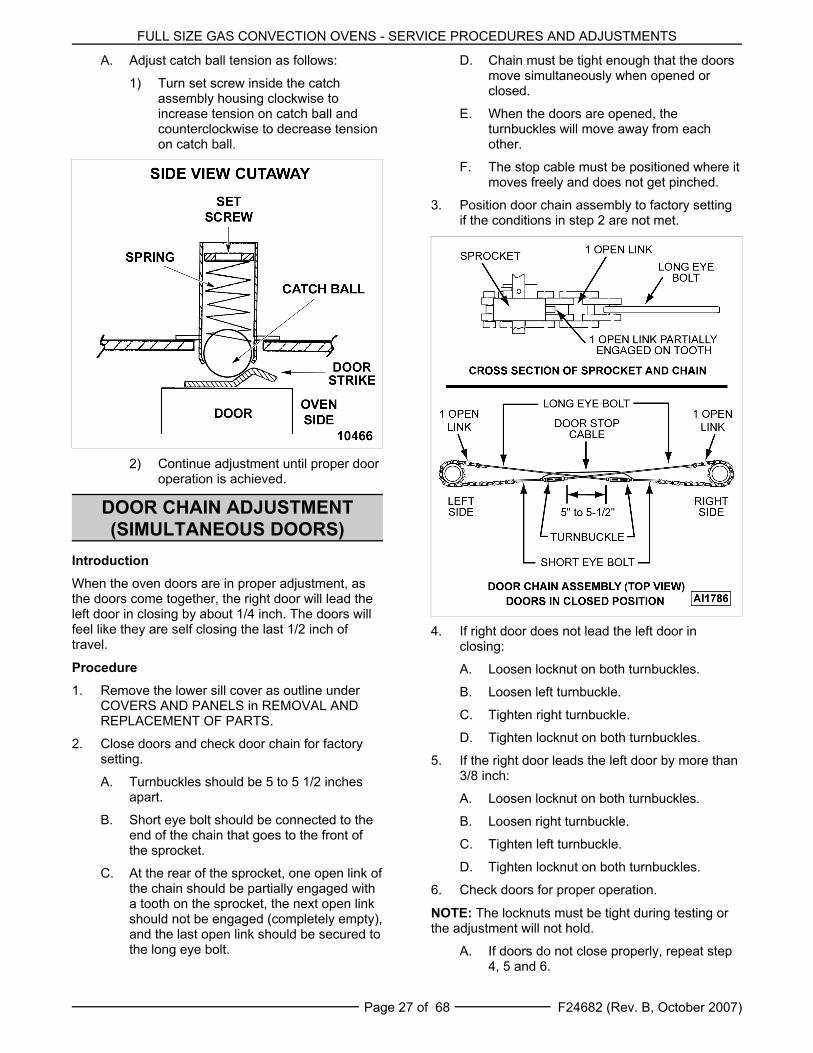
A. Adjust catch ball tension as follows:
1) Turn set screw inside the catchassembly housing clockwise toincrease tension on catch ball andcounterclockwise to decrease tensionon catch ball.
2) Continue adjustment until proper dooroperation is achieved.
DOOR CHAIN ADJUSTMENT(SIMULTANEOUS DOORS)
IntroductionWhen the oven doors are in proper adjustment, asthe doors come together, the right door will lead theleft door in closing by about 1/4 inch. The doors willfeel like they are self closing the last 1/2 inch oftravel.
Procedure1. Remove the lower sill cover as outline under
COVERS AND PANELS in REMOVAL ANDREPLACEMENT OF PARTS.
2. Close doors and check door chain for factorysetting.
A. Turnbuckles should be 5 to 5 1/2 inchesapart.
B. Short eye bolt should be connected to theend of the chain that goes to the front ofthe sprocket.
C. At the rear of the sprocket, one open link ofthe chain should be partially engaged witha tooth on the sprocket, the next open linkshould not be engaged (completely empty),and the last open link should be secured tothe long eye bolt.
D. Chain must be tight enough that the doorsmove simultaneously when opened orclosed.
E. When the doors are opened, theturnbuckles will move away from eachother.
F. The stop cable must be positioned where itmoves freely and does not get pinched.
3. Position door chain assembly to factory settingif the conditions in step 2 are not met.
4. If right door does not lead the left door inclosing:
A. Loosen locknut on both turnbuckles.
B. Loosen left turnbuckle.
C. Tighten right turnbuckle.
D. Tighten locknut on both turnbuckles.
5. If the right door leads the left door by more than3/8 inch:
A. Loosen locknut on both turnbuckles.
B. Loosen right turnbuckle.
C. Tighten left turnbuckle.
D. Tighten locknut on both turnbuckles.
6. Check doors for proper operation.
NOTE: The locknuts must be tight during testing orthe adjustment will not hold.
A. If doors do not close properly, repeat step4, 5 and 6.

FULL SIZE GAS CONVECTION OVENS - SERVICE PROCEDURES AND ADJUSTMENTS
F24682 (Rev. B, October 2007) Page 28 of 68
B. If doors operate properly, continue withprocedure.
7. Install the lower front cover.
COMPUTER CONTROL(VC4GC/VC6GC)
OperationRefer to the Instructions Manual for specificoperating instructions.
Setup Mode
NOTE: Use the setup mode to verify that the controlis configured to the factory settings which result inthe proper operation of the oven. If the CAL1parameter is other than zero, determine if it is stillneeded before resetting to zero. See COMPUTERCONTROL CALIBRATION (VC4GC/VC6CG).
Changing the C_F, InP1, rL1 & rH1parameters will default all menus.
1. Use this key sequence to access the setupmode.
Up arrow; Rack 1; Temperature; Temperature;Down arrow; Rack 1
2. Once in the setup mode the display willalternate between the parameter andprogrammed data.
• To change data to the factory setting, usethe arrow keys.
• To select the next parameter, press theRack 1 key.
• After the last Parameter and Data isviewed, press the Rack 1 key a final timeto exit the setup mode and return tooperations mode. The current set pointtemperature will be displayed.
• After 1 minute of no key activations, thecontrol will return to operation mode.
3. Listed are the parameters and data you shouldfind.
MENUALTERNATING ON
DISPLAY
PARAMETER DATACelsius_Fahrenheit C_F F
Guard Band gb 4000
TemperatureCompensation tcnP OFF
Input Type 1 InP1 J
Range Low 1 rL1 75
Range High 1 rH1 500
Hysteresis HYS1 3
Calibration Offset CAL1 0
Exit Setup Mode andreturn to OperationMode.
set point temperature isdisplayed or if call forheat, dashes (----)displayed.
Probe Test1. Set the control to 350EF.
2. Access the back of the control panel todisconnect the probe lead wires.
3. Install a jumper wire across the probe terminals.This will simulate room temperature.
A. If the heat light comes on and the actualtemperature is room temperature, replacethe probe.
B. If the heat light does not come on or theactual temperature is not roomtemperature, replace the control.
Solid State Relay Test1. Remove the right side panel as outlined under
COVERS AND PANELS.
2. Set the temperature to 350°F or high enough tokeep the heat ON for several minutes.
3. Check for +5 VDC on input side of SSR(terminals 3 & 4).
A. If +5 VDC is present, continue to step 4.
B. If no voltage is present, computer control isnot functioning properly.
4. Check for 120 VAC at load side of SSR(terminals 1 & 2).
A. If no voltage is present, solid state relay isnot functioning properly.
1) Replace the SSR and check forproper operation.
B. If 120 VAC is present, component isfunctioning properly.
FULL SIZE GAS CONVECTION OVENS - SERVICE PROCEDURES AND ADJUSTMENTS
F24682 (Rev. B, October 2007)Page 29 of 68
5. Re-assemble oven and check for properoperation.
COMPUTER CONTROLCALIBRATION
(VC4GC/VC6GC)
1. Place a thermocouple in the geometric center ofthe oven cavity.
2. Set the ON-OFF-COOL DOWN switch to ON.
A. If the set point temperature is 350°F,proceed to step 4.
B. If the set point temperature is other than350°F, proceed to step 3 to change thetemperature.
3. Press the set key then temperature key to enterthe temperature set mode.
A. The display will alternate between the termStPt (set point) and the current oventemperature setting.
B. Press the up or down arrow keys to makethe proper selection.
C. Press the set key again to save the changeand exit the temperature set mode.
4. Allow the oven temperature to stabilize(normally 3 cycles).
5. Compare the controls set point temperature tothe thermocouple meter reading when the heatlight goes out.
A. A temperature variance more than 5°Findicates an adjustment is needed.
1) To make the adjustment, proceed tostep 6.
2) If temperature variance is less than5°F, computer control is functioningproperly.
6. Enter the setup mode as outlined in SETUPMODE under COMPUTER CONTROL (VC4GC/VC6GC).
A. Advance through the menu until CAL1(Calibration Offset) appears.
1) If the thermocouple reading is higherthan set point temperature, press thedown arrow key and enter a negativeoffset value that is equal to thenumber of degrees above the 5°Ftolerance.
2) If the thermocouple reading is lowerthan set point temperature, press theup arrow key and enter a positiveoffset value that is equal to thenumber of degrees below the 5°Ftolerance.
3) Exit the setup mode.
7. Allow the oven to cycle at least two timesbetween adjustments.
A. If the temperature variance still differsmore than 5°F from the set point, verify thecorrect calibration offset value was enteredand retained.
1) Adjust the calibration offset value asoutlined in step 6, until the cyclingtemperature is within tolerance.
B. If the above adjustment cannot beobtained, replace the computer control andcheck for proper operation.

FULL SIZE GAS CONVECTION OVENS - ELECTRICAL OPERATION
F24682 (Rev. B, October 2007) Page 30 of 68
ELECTRICAL OPERATIONCOMPONENT FUNCTION
Power Switch (S1) . . . . . . . . . . . . . Determines the mode of operation; ON, OFF, or COOL DOWN.
Oven Light Switch (S2) . . . . . . . . . Controls the oven cavity lights.
Fan Speed Switch Hi/Low (S3) . . . Controls blower motor speed between Hi and Low settings. Available onstandard models VC4GS/6GS or VC4GD/6GD. On models with the ROAST& HOLD option (S3) becomes the Function Switch.
Function Switch (S3) . . . . . . . . . . . Selects the cooking mode of the oven between Normal ROAST or ROAST& HOLD and is used in conjunction with the ROAST & HOLD timer duringROAST & HOLD cooking. The selected mode also determines the fixedblower speed of Hi for Normal ROAST and Low for ROAST & HOLD. In ROAST & HOLD mode only, energizes the hold relay (R2). Available onmodels with ROAST & HOLD option only. On Standard models (S3)becomes the Function Switch.
Buzzer . . . . . . . . . . . . . . . . . . . . . . . Signals the end of a Normal ROAST cycle (normal cooking) when timeexpires on the Normal ROAST timer.
Normal Roast Timer . . . . . . . . . . . . Counts the ROAST time (normal cooking) of the product and signals thebuzzer at the end of the cycle. On ROAST & HOLD models only, when thefunction switch (S3) is set to Normal ROAST, this timer is used.
Roast & Hold Timer . . . . . . . . . . . . When the function switch (S3) is set to ROAST & HOLD, this timer mustused for ROAST & HOLD cooking. When the ROAST (then hold) timeexpires and the function switch is set to ROAST & HOLD, this timer is usedto transfer control of the oven temperature to the Hold thermostat. Availableon models with Roast & Hold option only.
Door Switch . . . . . . . . . . . . . . . . . . Allows the oven to operate when the doors are closed but stops the ovenfrom operating when the doors are opened.
Blower Motor . . . . . . . . . . . . . . . . . Operates the oven cavity blower (convection fan). Also, an internalcentrifugal switch on the motor is utilized to allow the connection of powerto the heat relay (R3) when the motor is at operating speed.
Motor Speed Relay (R1) . . . . . . . . . Supplies power to the blower motor through (R1) relay contacts. Availableon models with Roast & Hold option only.
Hold Relay (R2) . . . . . . . . . . . . . . . . Hold relay (R2) supplies power to the Hold thermostat for maintaining thefixed hold temperature in the oven cavity, after the ROAST & HOLD timeexpires.
Transformer (T1) . . . . . . . . . . . . . . . Provides 24VAC power to the ignition control module and heating circuit.
Solid State Temperature Control(VC4GD/6GD) . . . . . . . . . . . . . . . . . Monitors temperature sensor and regulates the oven cavity temperature by
controlling the heat relay (R3) through the blower motor centrifugal switchcontacts.
High Limit Thermostat . . . . . . . . . . Protects the oven from temperatures above 550°F by removing power fromthe 1st valve (safety) on the dual solenoid gas valve which stops the flow ofgas to the burner. Auto resets at 500°F.

FULL SIZE GAS CONVECTION OVENS - ELECTRICAL OPERATION
F24682 (Rev. B, October 2007)Page 31 of 68
Computer Control(VC4GC/6GC) . . . . . . . . . . . . . . . . . Monitors temperature sensor and regulates the oven cavity temperature by
controlling the heat relay (R1) through the blower motor centrifugal switchcontacts. Also, counts the ROAST time (normal cooking) of the product andsignals the electronic alarm at the end of the cycle. If ROAST & HOLDmode is selected, when the ROAST (then hold) time expires, the ovenheating stops and the oven enters HOLD mode. Once the oven cavitytemperature drops to 150°F, the heat comes back on and the oven cyclesat this temperature to hold the cooked product. Roast & Hold is standard oncomputer models.
SSR1 & SSR2 (VC4GC/6GC) . . . . . When SSR1 is energized by computer control, connects power to blowermotor for Hi fan speed operation in normal ROAST mode. In ROAST &HOLD Mode only, SSR1 is de-energized and SSR2 is energized bycomputer control and connects power to blower motor for Low fan speedoperation.
Ignition Control Module . . . . . . . . . Controls the gas ignition cycle - Energizes the 2nd valve (main) on the dualsolenoid gas valve, generates spark for burner ignition, monitors thepresence of a flame and controls the No Ignition light. The ignition timesare: 4 second self diagnostic test (initial power ON); 7 second ignition trial; 3 ignition trials with a 15 second purge between each trial.
Igniter/Flame Sense . . . . . . . . . . . . Ignites the gas and senses the presence of a flame. The flame presencegenerates a micro-amp FLAME SENSE current that is monitored by theignition control module. A flame sense current of 0.7 micro amp (minimum)is required to maintain burner ignition.
Power On Light . . . . . . . . . . . . . . . . Lit whenever the power switch (S1) is turned to ON or Cool Down mode.
Heat Light . . . . . . . . . . . . . . . . . . . . Lit whenever temperature control is calling for heat.
No Ignition Light . . . . . . . . . . . . . . . Lit when power is turned ON, during ignition trial & gas purge time andwhen no flame is detected by flame sensor. If the oven fails to ignite after 3attempts, it will remain lit until power is reset.
Temperature Probe . . . . . . . . . . . . Senses the oven temperature for the solid state temperature control or thecomputer control. On VC4GD/6D models, converts the temperature into aresistance valve which is monitored by the temperature control board. Theprobe is an RTD (resistance temperature detector) of the Thermistor type.As temperature increases the resistance value decreases.On VC4GC/6C models, the probe is a J type thermocouple.
Gas Valve (Dual Solenoid) . . . . . . . Allows gas flow to the burner when the 1st valve (safety) and 2nd valve(main) solenoid coils are both energized.
Cooling Fan . . . . . . . . . . . . . . . . . . . Circulates cooler air from rear of oven forward to cool components in thecontrol area.
Mechanical Temperature ControlKX Thermostat (VC4GS/6GS) . . . . Regulates the oven cavity temperature by controlling the heat relay (R3)
through the blower motor centrifugal switch contacts. On ROAST & HOLDmodels only, power is first connected through one set of (R4) normallyclosed contacts (N.C.) then through the centrifugal switch contacts on themotor.
Hold Thermostat (KX) . . . . . . . . . . Holds the oven cavity temperature at 160°F after ROAST (then hold) timeexpires. For the oven to operate on the Hold thermostat, the ROAST &HOLD timer must be used and the Function Switch (S3) must be set to.Available on models with Roast & Hold option only.

FULL SIZE GAS CONVECTION OVENS - ELECTRICAL OPERATION
F24682 (Rev. B, October 2007) Page 32 of 68
COMPONENT LOCATION

FULL SIZE GAS CONVECTION OVENS - ELECTRICAL OPERATION
F24682 (Rev. B, October 2007)Page 33 of 68
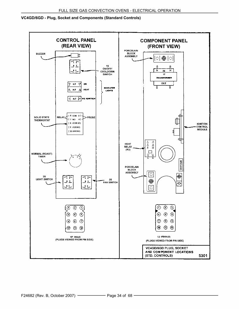
VC4GS/6GS - Plug, Socket and Components (Standard Controls)
FULL SIZE GAS CONVECTION OVENS - ELECTRICAL OPERATION
F24682 (Rev. B, October 2007) Page 34 of 68
VC4GD/6GD - Plug, Socket and Components (Standard Controls)

FULL SIZE GAS CONVECTION OVENS - ELECTRICAL OPERATION
F24682 (Rev. B, October 2007)Page 35 of 68
VC4GS/6GS, VC4GD/6GD - Plug, Socket and Components (Roast & Hold Option)

FULL SIZE GAS CONVECTION OVENS - ELECTRICAL OPERATION
F24682 (Rev. B, October 2007) Page 36 of 68
VC4GC/6GC - Plug, Socket and Components (Roast & Hold Standard)

FULL SIZE GAS CONVECTION OVENS - ELECTRICAL OPERATION
F24682 (Rev. B, October 2007)Page 37 of 68
SEQUENCE OF OPERATIONVC4GS, VC6GS With Roast & Hold Option(Mechanical KX Thermostat)Schematic diagram 5304 will be used to explain theelectrical sequence of operation for both the NormalROAST cycle (normal cooking) and the ROAST &HOLD cycle.
Normal Roast Cycle1. Conditions.
A. Oven connected to correct voltage.
1) L1 (HOT) to power switch (S1).
2) L2 (NEUTRAL or SECOND LINE) toone side of the following components:power ON light, heat light, oven cavitylights, buzzer, ROAST timer motor(normal cooking), ROAST & HOLDtimer motor, heat relay coil (R3),convection fan motor common (C),transformer primary (T1), relay coil(R4), motor speed (Hi/Low) relay coil(R1), hold relay coil (R2) and thecomponent cooling fan.
B. Oven properly grounded.
C. Gas supply valve ON.
D. Gas combination control valve ON.
E. Power switch (S1) OFF.
F. Function switch (S3) set to Normal ROASTcycle.
G. Oven light switch (S2) ON/OFF (positionhas no affect on the function of the NormalROAST cycle).
H. Control thermostat dial in the OFF position(OPEN).
I. High limit switch CLOSED.
J. Roast timer (normal cooking) in the OFFposition.
K. Roast and Hold timer in the OFF position.
L. Oven doors CLOSED.
1) Door switch contacts CLOSED.
M. Oven cavity temperature below 140°F.
2. Set thermostat to desired Normal ROASTtemperature (normal cooking).
A. Internal contacts close.
3. Power switch (S1) turned ON.
A. Power to motor speed (Hi/Low) relay (R1)normally open (N.O.) contacts and holdrelay (R2) common (C).
B. Component cooling fan energized.
C. Power ON light (Amber) comes ON.
D. Power to one side of the followingcomponents: Normal ROAST timerterminal 1, ROAST & HOLD timer terminal1, transformer primary (T1).
NOTE: Power is available to the oven lightswitch (wire #20) to turn the oven cavitylights ON when the light switch is turnedON; and power is available to the normallyopen N.O. side (wire #28) of the doorswitch contacts and connects power toadditional components when the doorswitch contacts are CLOSED (doorclosed).
1) Transformer (T1) energized.
a. Power (24VAC) to one side ofthe following components: heatrelay (R3) normally open (N.O.)contacts, high limit --- connectedthrough the normally closed(N.C.) contacts to the 1st valve(safety) on the dual solenoid gasvalve.
a) 1st valve (safety) on the gasvalve energized.
NOTE: Gas does not flow to theburner until the 2nd valve (main)is energized.
2) With door switch closed, power isconnected back through a second setof contacts on the power switch (S1),through the thermostat contacts,through one set of relay R4 normallyclosed (N.C.) contacts, to one side ofthe centrifugal switch on theconvection fan motor.
a. Heat light (clear) comes ON.
3) Power is also connected through theother set of relay R4 normally closed(N.C.) contacts to the other side ofmotor speed relay (R1).
a. Motor speed relay (R1)energized, contacts change stateand the normally open (N.O.) setof contacts close.
a) Power is connected throughthe function switch (S3)contacts and the convectionfan motor is energized (fanspeed Hi).
FULL SIZE GAS CONVECTION OVENS - ELECTRICAL OPERATION
F24682 (Rev. B, October 2007) Page 38 of 68
b. When the convection fan motorreaches operating speed, thecentrifugal switch on the motorcloses. The heat relay (R3) isthen energized, R3 relaycontacts normally open (N.O.)close and the heating circuit ispowered.
a) Ignition control module isenergized.
b) No ignition light (red) comesON, module performs a selfdiagnostic test for 4seconds, 2nd valve (main)on the gas valve isenergized. Gas starts to flowto the burner, sparkingbegins, the NO IGNITIONlight goes out and burnerlights. Sparking continuesfor up to 7 seconds or until aflame is established. If aflame is SENSED, the NOIGNITION light stays outand burner remains lit.
If a flame is not SENSEDafter 7 seconds of sparking,the NO IGNITION lightcomes back on, 2nd valve(main) on the gas valve isde-energized and gas flowto the burner stops. Ignitiontrial cycle repeats after a 15second purge betweencycles for two additionaltries before locking out. Toreset after a lockout, turnpower switch (S1) OFF thenON.
4. Oven reaches set temperature and thermostatopens.
A. Heat light goes out.
B. Power removed from heat relay (R3).
1) R3 normally open (N.O.) contactsopen.
a. Power removed from 2nd valve(main) on the gas valve and gasflow to the burner stops.
5. The oven will continue to cycle on thethermostat until the doors are opened or thepower switch (S1) is turned to the OFF orCOOL DOWN position.
Timer Cycle (Normal Roast Cooking)
NOTE: The ROAST timer (normal cooking) operatesindependently of the heating cycle. Additional timecan be set or the timer can be turned OFFthroughout the cooking cycle.
1. With the power switch turned ON, power issupplied to timer.
2. Set ROAST timer to desired time (normalcooking).
A. Contacts 1 & 3 close, timer motor isenergized and timing DOWN begins.
3. Time expires on ROAST timer (normal cooking).
A. Contacts 1 & 3 open, timer motor is de-energized and timing stops.
B. Contacts 1 & 4 close.
1) Buzzer energized and sounds.
NOTE: The buzzer continues to sound untilthe timer dial is set to the OFF position oradditional time is set.
Roast and Hold Cycle
NOTE: Refer to the Installation and OperationManual for a detailed explanation of ROAST &HOLD cooking.
1. Conditions.
A. Oven connected to correct voltage.
1) L1 (HOT) to power switch (S1).
2) L2 (NEUTRAL or SECOND LINE) toone side of the following components:power ON light, heat light, oven cavitylights, buzzer, ROAST timer motor(normal cooking), ROAST & HOLDtimer motor, heat relay coil (R3),convection fan motor (C), transformerprimary (T1), relay coil (R4), motorspeed relay coil (R1), hold relay coil(R2) and the component cooling fan.
B. Oven properly grounded.
C. Gas supply valve ON.
D. Gas combination control valve ON.
E. Power switch (S1) OFF.
F. Function switch (S3) set to ROAST &HOLD cycle.
G. Oven light switch (S2) ON/OFF (positionhas no affect on the function of the Roast &Hold cycle).
H. Control thermostat in the OFF position(OPEN).
I. High limit switch CLOSED.
FULL SIZE GAS CONVECTION OVENS - ELECTRICAL OPERATION
F24682 (Rev. B, October 2007)Page 39 of 68
J. Roast timer (normal cooking) in the OFFposition.
K. Roast and Hold timer in the OFF position.
L. Oven doors Closed.
1) Door switch contacts CLOSED.
M. Oven cavity temperature below 140°F.
2. Set controlling thermostat to desired ROASTthen Hold temperature (Roast & Hold cooking).
NOTE: This is considered first stage cooking in theROAST & HOLD cycle.
A. Internal contacts close.
3. Power switch (S1) turned ON.
A. Power to motor speed (Hi/Low) relay (R1)normally open (N.O.) contacts and holdrelay (R2) common (C).
B. Component cooling fan energized.
C. Power ON light (Amber) comes ON.
D. Power to one side of the followingcomponents: Normal ROAST timerterminal 1, ROAST & HOLD timer terminal1, transformer primary (T1).
NOTE: Power is available to the oven lightswitch (wire #20) to turn the oven cavitylights ON when the light switch is turnedON; and power is available to the normallyopen N.O. side (wire #28) of the doorswitch contacts and connects power toadditional components when the doorswitch contacts are CLOSED (doorclosed).
1) Transformer (T1) energized.
a. Power (24VAC) to one side ofthe following components: heatrelay (R3) normally open (N.O.)contacts, high limit—connectedthrough the normally closed(N.C.) contacts to the 1st valve(safety) on the dual solenoid gasvalve.
a) 1st valve (safety) on the gasvalve energized.
NOTE: Gas does not flow to theburner until the 2nd valve (main)is energized.
2) With door switch closed, power isconnected through a second set ofcontacts on the power switch (S1),through the thermostat contacts,through one set of relay R4 normallyclosed (N.C.) contacts, to one side ofthe centrifugal switch on theconvection fan motor.
a. Heat light (clear) comes ON.3) Power is also connected through the
another set of relay R4 normallyclosed (N.C.) contacts to the otherside of motor speed relay (R1).a. Motor speed relay (R1)
energized, contacts change stateand the normally open (N.O.) setof contacts close.a) Convection fan motor
energized (fan speed low).NOTE: In the ROAST & HOLDcycle, the fan speed is fixed atlow.
b. When the convection fan motorreaches operating speed, thecentrifugal switch on the motorcloses. The heat relay (R3) isthen energized, R3 relaycontacts normally open (N.O.)close and the heating circuit ispowered.a) Ignition control module is
energized.b) No ignition light (red) comes
ON, module performs a selfdiagnostic test for 4seconds, 2nd valve (main)on the gas valve isenergized. Gas starts to flowto the burner, sparkingbegins, the NO IGNITIONlight goes out and burnerlights. Sparking continuesfor up to 7 seconds or until aflame is established. If aflame is SENSED, the NOIGNITION light stays outand burner remains lit.If a flame is not SENSEDafter 7 seconds of sparking,the NO IGNITION lightcomes back on, 2nd valve(main) on the gas valve isde-energized and gas flowto the burner stops. Ignitiontrial cycle repeats after a 15second purge betweencycles for two additionaltries before locking out. Toreset after a lockout, turnpower switch (S1) OFF thenON.
4. Oven reaches set temperature and controllingthermostat opens.
A. Heat light goes out.
B. Power removed from heat relay (R3).
FULL SIZE GAS CONVECTION OVENS - ELECTRICAL OPERATION
F24682 (Rev. B, October 2007) Page 40 of 68
1) R3 normally open (N.O.) contactsopen.
a. Ignition control module de-energized.
a) Power removed from 2nd
valve (main) on the gasvalve and gas flow to theburner stops.
NOTE: This is considered firststage cooking in the ROASTAND HOLD cycle.
5. The oven will continue to cycle on thecontrolling thermostat until one of the followingoccurs: ROAST & HOLD time (R & H cooking)expires which allows the oven to go into Holdmode; Power switch (S1) is turned to the OFFor COOL DOWN position or the doors areopened.
Timer Cycle (Roast & Hold Cooking)
NOTE: The ROAST & HOLD timer operatesindependently of the heating cycle until time expires.Regulation of the oven temperature is thentransferred to the Hold thermostat until one of thefollowing occurs: ROAST & HOLD timer is turnedOFF and the function switch (S3) is turned back toNormal ROAST (normal cooking) or power switch(S1) is turned to the OFF or COOL DOWN position.
1. With the power switch turned ON, power issupplied to timer.
2. Set ROAST & HOLD timer to desired time(Roast & Hold cooking).
NOTE: To Roast then Hold the cooked product at afixed temperature, the Roast & Hold timer must beused and the function switch (S3) must also be set toRoast & Hold as indicated under step1 conditions forthe Roast & Hold cycle.
A. Contacts 1 & 3 close, timer motor isenergized and timing DOWN begins.
3. Time expires on Roast & Hold timer.
A. Contacts 1 & 3 open, timer motor is de-energized and timing stops.
B. Contacts 1 & 4 close.
1) If the oven was heating, then the gasburner and heat light go out; If theoven was not heating, then the gasburner and heat light remain out.
2) Hold relay (R2) is energized, R2contacts change state and thenormally open (N.O.) contacts close.
a. Power to one side of holdthermostat.
NOTE: When temperature is above160°F (±12) the hold thermostatcontacts are open.
3) Relay R4 is energized, R4 contactschange state and both sets ofnormally closed (N.C.) contactstransfer to the normally open (N.O.)position. Power is not transferred untilthe hold thermostat contacts close.
NOTE: This is considered second stagecooking in the ROAST AND HOLD cyclewhere the stored heat in the ovencontinues to cook the product.
4. Oven temperature falls below 160°F (±12) andhold thermostat contacts close.
A. Heat light comes ON.
B. Motor speed relay (R1) is energizedthrough one set of R4 (N.C.) contacts.
1) Convection fan motor energized (fanspeed low).
C. Power is applied to one side of thecentrifugal switch on the convection fanmotor through the other set of R4 (N.C.)contacts.
D. When the convection fan motor reachesoperating speed, the centrifugal switch onthe motor closes.
1) Heat relay (R3) is energized.
a. Heat relay (R3) contacts (N.O.)close and the heating circuit ispowered.
a) Ignition control module isenergized.
b) No ignition light (red) comesON, module performs a selfdiagnostic test for 4seconds, 2nd valve (main)on the gas valve isenergized. Gas starts to flowto the burner, sparkingbegins, the NO IGNITIONlight goes out and burnerlights. Sparking continuesfor up to 7 seconds or until aflame is established. If aflame is SENSED, the NOIGNITION light stays outand burner remains lit.

FULL SIZE GAS CONVECTION OVENS - ELECTRICAL OPERATION
F24682 (Rev. B, October 2007)Page 41 of 68
If a flame is not SENSEDafter 7 seconds of sparking,the NO IGNITION lightcomes back on, 2nd valve(main) on the gas valve isde-energized and gas flowto the burner stops. Ignitiontrial cycle repeats after a 15second purge betweencycles for two additionaltries before locking out. Toreset after a lockout, turnpower switch (S1) OFF thenON.
5. Oven reaches the fixed HOLD temperature andthe hold thermostat opens.
A. Heat light goes out.
B. Power removed from heat relay (R3) andthe contacts open (N.O.).
1) Ignition control module de-energized.
a. Power removed from 2nd valve(main) on the gas valve and gasflow to the burner stops.
C. Power is also removed from motor speedrelay (R1).
1) Convection fan motor de-energizedand fan stops rotating.
6. The oven will continue to cycle on the holdthermostat until the ROAST & HOLD timer isturned to the OFF position, the function switch(S3) is changed back to ROAST (normalcooking) or the power switch (S1) is turned tothe OFF or COOL DOWN position.
VC4GD, VC6GD With Roast & Hold Option (SolidState Temperature Control)Schematic diagram 5306 will be used to explain theelectrical sequence of operation for both the NormalROAST cycle (normal cooking) and the ROAST &HOLD cycle.
Normal Roast Cycle1. Conditions.
A. Oven connected to correct voltage.
1) L1 (HOT) to power switch (S1).
2) L2 (NEUTRAL or SECOND LINE) toone side of the following components:power ON light, heat light,temperature control board terminal 9(120VAC) or terminal 10 (208-240VAC), oven cavity lights, buzzer,ROAST timer motor (normal cooking),ROAST & HOLD timer motor, heatrelay coil (R3), convection fan motorcommon (C), transformer primary(T1), motor speed (Hi/Low) relay coil(R1), hold relay coil (R2) and thecomponent cooling fan.
B. Oven properly grounded.
C. Gas supply valve ON.
D. Gas combination control valve ON.
E. Power switch (S1) OFF.
F. Function switch (S3) set to Normal ROASTcycle.
G. Oven light switch (S2) ON/OFF (positionhas no affect on the function of the NormalROAST cycle).
H. Temperature control dial set to lowesttemperature (fully counterclockwise).
I. High limit switch CLOSED.
J. Roast timer (normal cooking) in the OFFposition.
K. Roast and Hold timer in the OFF position.
L. Oven doors Closed.
1) Door switch contacts CLOSED.
M. Oven cavity temperature below 140°F.
2. Set temperature control dial to desired ROASTthen HOLD temperature (Roast & Holdcooking).
3. Power switch (S1) turned ON.
A. Component cooling fan energized.
B. Power ON light (Amber) comes ON.
C. Power to one side of the followingcomponents: Normal ROAST timerterminal 1, ROAST & HOLD timer terminal1, transformer primary (T1).
NOTE: Power is available to the oven lightswitch (wire #20) to turn the oven cavity lightsON when the light switch is turned ON; andpower is available to the normally open N.O.side (wire #28) of the door switch contacts andconnects power to additional components whenthe door switch contacts are CLOSED (doorclosed).

FULL SIZE GAS CONVECTION OVENS - ELECTRICAL OPERATION
F24682 (Rev. B, October 2007) Page 42 of 68
1) Transformer (T1) energized.
a. Power (24VAC) to one side ofthe following components: heatrelay (R3) normally open (N.O.)contacts, high limit --- connectedthrough the normally closed(N.C.) contacts to the 1st valve(safety) on the dual solenoid gasvalve.
a) 1st valve (safety) on the gasvalve energized.
NOTE: Gas does not flow to theburner until the 2nd valve (main)is energized.
2) With door switch closed, power isapplied to motor speed (Hi/Low) relay(R1) normally open (N.O.) contactsand hold relay (R2) common (C).
a. Motor speed relay (R1) isenergized through hold relay(R2) normally closed contacts(N.C.). Relay contacts (R1)change state and the normallyopen (N.O.) set of contacts close.
a) Power is connected throughthe function switch (S3)contacts and convection fanmotor is energized (fanspeed hi).
b) When the convection fanmotor reaches operatingspeed, the centrifugal switch(N.O.) on the motor closes.
c) Power to normally open(N.O.) side of internal relaycontacts (terminal 7) on thetemperature control board.
3) Power is also connected back througha second set of contacts on the powerswitch (S1) to terminal 8 on thetemperature control board.
a. Solid state temperature controlenergized. If the oventemperature is below set point,the temperature control willenergize its internal relay. Thenormally open (N.O.) contactsclose and apply power to thefollowing components:
a) Heat light (clear) comes ON.
b) Power is connected throughthe centrifugal switchcontacts on the convectionfan motor, heat relay (R3) isenergized, (R3) contacts(N.O.) close and the heatingcircuit is powered.
c) Ignition control module isenergized.
d) No ignition light (red) comesON, module performs a selfdiagnostic test for 4seconds, 2nd valve (main)on the gas valve isenergized. Gas starts to flowto the burner, sparkingbegins, the NO IGNITIONlight goes out and burnerlights. Sparking continuesfor up to 7 seconds or until aflame is established. If aflame is SENSED, the NOIGNITION light stays outand burner remains lit.
If a flame is not SENSEDafter 7 seconds of sparking,the NO IGNITION lightcomes back on, 2nd valve(main) on the gas valve isde-energized and gas flowto the burner stops. Ignitiontrial cycle repeats after a 15second purge betweencycles for two additionaltries before locking out. Toreset after a lockout, turnpower switch (S1) OFF thenON.
4. Oven reaches set temperature.
A. Temperature control de-energizes internalrelay and the normally open (N.O.)contacts OPEN.
1) Heat light goes out.
2) Power removed from heat relay (R3).
a. R3 normally open (N.O.) contactsOPEN.
a) Power removed from 2nd
valve (main) on the gasvalve and gas flow to theburner stops.
5. The oven will continue to cycle on thetemperature control until the doors are openedor power switch (S1) is turned to the OFF orCOOL DOWN position.
FULL SIZE GAS CONVECTION OVENS - ELECTRICAL OPERATION
F24682 (Rev. B, October 2007)Page 43 of 68
Timer Cycle (Normal Roast Cooking)
NOTE: The ROAST timer (normal cooking) operatesindependently of the heating cycle. Additional timecan be set or the timer can be turned OFFthroughout the cooking cycle.
1. With the power switch turned ON, power issupplied to timer.
A. Set ROAST timer to desired time (normalcooking).
B. Contacts 1 & 3 close, timer motor isenergized and timing DOWN begins.
2. Time expires on ROAST timer (normal cooking).
A. Contacts 1 & 3 open, timer motor is de-energized and timing stops.
B. Contacts 1 & 4 close.
1) Buzzer energized and sounds.
NOTE: The buzzer continues to sound untilthe timer dial is set to the OFF position oradditional time is set.
Roast and Hold Cycle
NOTE: Refer to the Installation and OperationManual for a detailed explanation of ROAST &HOLD cooking.
1. Conditions.
A. Oven connected to correct voltage.
1) L1 (HOT) to power switch (S1).
2) L2 (NEUTRAL or SECOND LINE) toone side of the following components:power ON light, heat light,temperature control board terminal 9(120VAC) or terminal 10 (208-240VAC), oven cavity lights, buzzer,ROAST timer motor (normal cooking),ROAST & HOLD timer motor, heatrelay coil (R3), convection fan motorcommon (C), transformer primary(T1), motor speed (Hi/Low) relay coil(R1), hold relay coil (R2) and thecomponent cooling fan.
B. Oven properly grounded.
C. Gas supply valve ON.
D. Gas combination control valve ON.
E. Power switch (S1) OFF.
F. Function switch (S3) set to ROAST &HOLD cycle.
G. Oven light switch (S2) ON/OFF (positionhas no affect on the function of the ROAST& HOLD cycle).
H. Temperature control dial set to lowesttemperature (fully counterclockwise).
I. High limit switch CLOSED.
J. Roast timer (normal cooking) in the OFFposition.
K. Roast and Hold timer in the OFF position.
L. Oven doors Closed.
1) Door switch contacts CLOSED.
M. Oven cavity temperature below 140°F.
2. Set temperature control dial to desired ROASTthen Hold temperature (Roast & Hold cooking).
3. Power switch (S1) turned ON.
A. Component cooling fan energized.
B. Power ON light (Amber) comes ON.
C. Power to one side of the followingcomponents: Normal ROAST timerterminal 1, ROAST & HOLD timer terminal1, transformer primary (T1).
NOTE: Power is available to the oven lightswitch (wire #20) to turn the oven cavity lightsON when the light switch is turned ON; andpower is available to the normally open N.O.side (wire #28) of the door switch contacts andconnects power to additional components whenthe door switch contacts are CLOSED (doorclosed).
1) Transformer (T1) energized.
a. Power (24VAC) to one side ofthe following components: heatrelay (R3) normally open (N.O.)contacts, high limit --- connectedthrough the normally closed(N.C.) contacts to the 1st valve(safety) on the dual solenoid gasvalve.
a) 1st valve (safety) on the gasvalve energized.
NOTE: Gas does not flow to theburner until the 2nd valve (main)is energized.
2) With door switch closed, power isapplied to motor speed (Hi/Low) relay(R1) normally open (N.O.) contactsand hold relay (R2) common (C).
a. Motor speed relay (R1) isenergized through hold relay(R2) normally closed contacts(N.C.). Relay contacts (R1)change state and the normallyopen (N.O.) set of contacts close.
FULL SIZE GAS CONVECTION OVENS - ELECTRICAL OPERATION
F24682 (Rev. B, October 2007) Page 44 of 68
a) Power is connected throughthe function switch (S3)contacts and convection fanmotor is energized (fanspeed low).
NOTE: In the ROAST & HOLDcycle, the fan speed is fixed atlow.
b) When the convection fanmotor reaches operatingspeed, the centrifugal switch(N.O.) on the motor closes.
c) Power to normally open(N.O.) side of internal relaycontacts (terminal 7) on thetemperature control board.
3) Power is also connected back througha second set of contacts on the powerswitch (S1) to terminal 8 on thetemperature control board.
a. Solid state temperature controlenergized. If the oventemperature is below set point,the temperature control willenergize its internal relay. Thenormally open (N.O.) contactsclose and apply power to thefollowing components:
a) Heat light (clear) comes ON.
b) Power is connected throughthe centrifugal switchcontacts on the convectionfan motor, heat relay (R3) isenergized, (R3) contacts(N.O.) close and the heatingcircuit is powered.
c) Ignition control module isenergized.
d) No ignition light (red) comesON, module performs a selfdiagnostic test for 4seconds, 2nd valve (main)on the gas valve isenergized. Gas starts to flowto the burner, sparkingbegins, the NO IGNITIONlight goes out and burnerlights. Sparking continuesfor up to 7 seconds or until aflame is established. If aflame is SENSED, the NOIGNITION light stays outand burner remains lit.
If a flame is not SENSEDafter 7 seconds of sparking,the NO IGNITION lightcomes back on, 2nd valve(main) on the gas valve isde-energized and gas flowto the burner stops. Ignitiontrial cycle repeats after a 15second purge betweencycles for two additionaltries before locking out. Toreset after a lockout, turnpower switch (S1) OFF thenON.
4. Oven reaches set temperature.
A. Temperature control de-energizes internalrelay and the normally open (N.O.)contacts OPEN.
1) Heat light goes out.
2) Power removed from heat relay (R3).
a. R3 normally open (N.O.)contacts OPEN.
a) Power removed from 2nd
valve (main) on the gasvalve and gas flow to theburner stops.
NOTE: This is considered firststage cooking in the ROAST &HOLD cycle.
5. The oven will continue to cycle on thetemperature control until one of the followingoccurs: ROAST & HOLD time (R & H cooking)expires which allows the oven to go into Holdmode; Power switch (S1) is turned to the OFFor COOL DOWN position or the doors areopened.
Timer Cycle (Roast & Hold Cooking)
NOTE: The ROAST & HOLD timer operatesindependently of the heating cycle until time expires.Regulation of the oven temperature is then turnedover to the Hold thermostat until one of the followingoccurs: ROAST & HOLD timer is turned OFF;function switch (S3) is turned back to NormalROAST (normal cooking) or Power switch (S1) isturned to the OFF or COOL DOWN position.
1. With the power switch turned ON, power issupplied to timer.
2. Set ROAST & HOLD timer to desired time(Roast & Hold cooking).
NOTE: To Roast then Hold the cooked product at afixed temperature, the Roast & Hold timer must beused and the function switch (S3) must also be set toRoast & Hold as indicated under step1 conditions forthe Roast & Hold cycle.

FULL SIZE GAS CONVECTION OVENS - ELECTRICAL OPERATION
F24682 (Rev. B, October 2007)Page 45 of 68
A. Contacts 1 & 3 close, timer motor isenergized and timing DOWN begins.
3. Time expires on Roast & Hold timer.
A. Contacts 1 & 3 open, timer motor is de-energized and timing stops.
B. Contacts 1 & 4 close.
1) If the oven was heating, then the gasburner and heat light go out; If theoven was not heating, then the gasburner and heat light remain out.
NOTE: The Temperature control boardremains powered and the internal relaycontacts remain closed as long as ovencavity temperature is below the 175°Fminimum set point temperature of theboard and power is ON.
2) Power is connected through functionswitch (S3) --- Hold relay (R2) is thenenergized, R2 contacts change stateand the normally open (N.O.) contactsclose.
a. Power to one side of holdthermostat.
NOTE: When temperature is above160°F (±12) the hold thermostatcontacts are open.
3) Motor speed relay (R1) de-energized,(R1) contacts change state and thenormally open (N.O.) contacts OPEN.
a. Convection fan motor stops andcentrifugal switch (N.O.) onmotor OPENS.
a) Heat relay (R3) de-energized, relay (R3)contacts open and ovenheating stops.
NOTE: This is consideredsecond stage cooking in theROAST & HOLD cycle where thestored heat in the oven continuesto cook the product.
4. Oven temperature falls below 160°F (±12) andhold thermostat contacts close.
A. Heat light comes ON.
B. Motor speed relay (R1) is energized, (R1)contacts change state and the normallyopen (N.O.) contacts CLOSE.
1) Convection fan motor energized (fanspeed low).
C. Power is also applied to one side of thecentrifugal switch on the convection fanmotor through the temperature controlinternal relay (N.O.) contacts.
D. When the convection fan motor reachesoperating speed, the centrifugal switch onthe motor closes.
1) Heat relay (R3) is energized.
a. Heat relay (R3) contacts (N.O.)close and the heating circuit ispowered.
a) Ignition module isenergized.
b) No ignition light (red) comesON, module performs a selfdiagnostic test for 4seconds, 2nd valve (main)on the gas valve isenergized. Gas starts to flowto the burner, sparkingbegins, the NO IGNITIONlight goes out and burnerlights. Sparking continuesfor up to 7 seconds or until aflame is established. If aflame is SENSED, the NOIGNITION light stays outand burner remains lit.
If a flame is not SENSEDafter 7 seconds of sparking,the NO IGNITION lightcomes back on, 2nd valve(main) on the gas valve isde-energized and gas flowto the burner stops. Ignitiontrial cycle repeats after a 15second purge betweencycles for two additionaltries before locking out. Toreset after a lockout, turnpower switch (S1) OFF thenON.
5. Oven reaches the FIXED hold temperature andhold thermostat opens.
A. Heat light goes out.
B. Power removed from heat relay (R3) andthe contacts open (N.O.).
1) Ignition control module de-energized.
a. Power removed from 2nd valve(main) on the gas valve and gasflow to the burner stops.
C. Power is also removed from motor speedrelay (R1).
1) Convection fan motor de-energizedand fan stops rotating.

FULL SIZE GAS CONVECTION OVENS - ELECTRICAL OPERATION
F24682 (Rev. B, October 2007) Page 46 of 68
6. The oven will continue to cycle on the holdthermostat until the ROAST & HOLD timer isturned to the OFF position and the functionswitch (S3) is change back to ROAST (normalcooking) or the power switch (S1) is turned tothe OFF or COOL DOWN position.
Cool Down Cycle (Solid State TemperatureControl)
NOTE: The electrical sequence of operation for theCOOL DOWN cycle is written for ovens with theROAST & HOLD option.
1. Conditions.
A. Oven is ON.
B. Oven cavity temperature needs to belowered.
C. Doors are open.
1) Door switch contacts OPEN.
D. Roast and Hold timer in the OFF position.
E. Roast timer (normal cooking) in the OFFposition.
F. Function switch (S3) set to either NormalROAST cycle or ROAST & HOLD cycle.
2. Power Switch (S1) turned to COOL DOWN.
NOTE: With door switch contacts OPEN (doorsopen), the convection fan motor will still run andcontinue to cool the oven. However, power would beremoved from the following components: Power ONlight (goes out), Normal ROAST timer, ROAST &HOLD timer, transformer T1 (de-energized) and tothe component cooling fan.
A. Power to motor speed (Hi/Low) relay (R1)normally open (N.O.) contacts and tocommon (C) on hold relay (R2). Power isthen connected through hold relay (R2)normally closed (N.C.) contacts to motorspeed (Hi/Low) relay (R1) coil.
1) Motor speed (Hi/Low) relay (R1) isenergized and contacts change state.
a. Power is connected throughmotor speed (Hi/Low) relaynormally open (N.O.) contacts,through function switch (S3) toConvection fan motor.
a) Convection fan motorenergized.
NOTE: If function switch (S3) isset to Normal ROAST cycle, fanspeed will be high; if set toROAST & HOLD cycle, fanspeed will be low.
b) When Convection fan motorreaches operating speed thecentrifugal switch on themotor closes but no poweris available for connection toother components.
B. Power to one side of the hold thermostatcontacts but is not transferred to othercomponents due to oven cavitytemperature above 160°F (thermostatOPEN).
C. Power to terminal 7 on the solid statetemperature control but is not transferredto other components due to temperaturecontrol not being powered.
3. If door switch is CLOSED (doors closed), poweris supplied to one side of the followingcomponents: Power ON light (Amber), ovenlight switch (S2), Normal ROAST timer terminal1, ROAST & HOLD timer terminal 1,transformer primary (T1) and componentcooling fan.
1) Power ON light (Amber) comes ON.
2) Transformer (T1) energized.
a. Power (24VAC) to one side ofthe following components: heatrelay (R3) normally open (N.O.)contacts, high limit --- connectedthrough the normally closed(N.C.) contacts to the 1st valve(safety) on the dual solenoid gasvalve.
a) 1st valve (safety) on the gasvalve energized.
NOTE: Gas does not flow to theburner until the 2nd valve (main)is energized.
3) Component cooling fan.
4. The oven will remain in this condition until thepower switch (S1) is turned to the OFF or ONposition.
VC4GC, VC6GC(Roast & Hold Standard on Computer Model)
Schematic diagram 10437 will be used to explain theelectrical sequence of operation for both the ROASTcycle (normal cooking) and the ROAST & HOLDcycle.

FULL SIZE GAS CONVECTION OVENS - ELECTRICAL OPERATION
F24682 (Rev. B, October 2007)Page 47 of 68
Roast Cycle (Normal Cooking)1. Conditions.
A. Oven connected to correct voltage.
1) L1 (HOT) to power switch (S1).
2) L2 (NEUTRAL or SECOND LINE) toone side of the following components:oven cavity lights, convection fanmotor common (C), transformerprimary (T1), component cooling fanand the heat relay coil (R1).
B. Oven properly grounded.
1) Ground (GND) to one side of thefollowing components: computercontrol case, NO IGNITION light, transformer secondary (T1), ignitioncontrol module, the 1st valve (safety)and 2nd valve (main) on the dualsolenoid gas valve and computercontrol pin 9 (C3-9).
C. Gas supply valve ON.
D. Gas combination control valve ON.
E. Power switch (S1) OFF.
F. Computer control is setup properly andready to use.
G. Oven light switch (S2) ON/OFF (positionhas no affect on the function of the ROASTcycle).
H. High limit switch CLOSED.
I. Oven doors Closed.1) Door switch contacts CLOSED.
J. Oven cavity temperature below 140°F.2. Power switch (S1) turned ON.
A. Power (120VAC) to computer control pin 3(C3-3).NOTE: Power at pin 3 is not transferred toother components until computer control isenergized and operating conditions aremet.
B. Power is available to the oven light switch(S2).
C. Power to terminal 1 on solid state relay 1(SSR1 -load side) and solid state relay 2(SSR2 -load side).
D. Component cooling fan energized.E. Transformer (T1) is energized.
1) Power (24VAC) to one side of thefollowing components: heat relay (R1)normally open (N.O.) contacts, highlimit --- connected through thenormally closed (N.C.) contacts to the1st valve (safety) on the dual solenoidgas valve.
a. 1st valve (safety) on the gas valveenergized.NOTE: Gas does not flow to theburner until the 2nd valve (main)is energized.
2) Power (24VAC) to the oven computercontrol.a. Control is energized and
performs a power ON self testbefore energizing outputs.NOTE: If the control passes selftest, then the outputs areenergized and operationsequence continues. If controldoes not pass self test then thecorresponding error code isdisplayed.
b. Computer control senses ovencavity temperature.a) With the oven cavity
temperature below set point,the controls 120VAC outputfrom pin C3-2 is activatedand power is connected tothe common (C) side of thecentrifugal switch contactson the convection fan motor.NOTE: The set pointtemperature of the computercontrol will be the lasttemperature that was set.NOTE: Power is not appliedto the heat relay coil (R1)until the centrifugal switchcontacts on the convectionfan motor close.
c. The controls 5VDC output frompins C2-2 (-) and C2-8 (+) isactivated and SSR1 relay isenergized.
a) Convection fan motor isenergized (fan speed hi).
b) When the convection fanmotor reaches operatingspeed, the centrifugal switch(N.O.) on the motor closes.
3) With the 120VAC output from thecontrol activated and the centrifugalswitch on the convection fan motorclosed, power is applied to the heatrelay coil (R1).
a. Heat relay coil (R1) is energized,(R1) contacts (N.O.) close andthe heating circuit is powered.
b. Oven HEAT LIGHT on thecontrol comes ON.
FULL SIZE GAS CONVECTION OVENS - ELECTRICAL OPERATION
F24682 (Rev. B, October 2007) Page 48 of 68
c. Ignition control module isenergized.
a) No ignition light (red) comesON, module performs a selfdiagnostic test for 4seconds, 2nd valve (main)on the gas valve isenergized. Gas starts to flowto the burner, sparkingbegins, the NO IGNITIONlight goes out and burnerlights. Sparking continuesfor up to 7 seconds or until aflame is established. If aflame is SENSED, the NOIGNITION light stays outand burner remains lit.
If a flame is not SENSEDafter 7 seconds of sparking,the NO IGNITION lightcomes back on, 2nd valve(main) on the gas valve isde-energized and gas flowto the burner stops. Ignitiontrial cycle repeats after a 15second purge betweencycles for two additionaltries before locking out. Toreset after a lockout, turnpower switch (S1) OFF thenON.
3. Oven reaches set point temperature.
A. Computer control de-activates the 120VACoutput to heat relay (R1).
1) Heat relay (R1) de-energized and thenormally open (N.O.) contacts OPEN.
a. Power removed from ignitioncontrol module.
a) The 2nd valve (main) on thegas valve is de-energizedand gas flow to the burnerstops.
B. Oven HEAT LIGHT on the control goesout.
C. Oven READY LIGHT on the control comesON.
D. Electronic beeper sounds momentarily.
4. The oven will continue to cycle on the computercontrol until the doors are opened or powerswitch (S1) is turned to the OFF or COOLDOWN position.
Temperature and Time Cycle (Cooking)
NOTE: The computers internal COOK timer operatesindependently of the heating cycle. Additional timecan be set or the timer can be stopped and re-started throughout the cooking cycle.
Refer to the Instructions Manual for specificoperating instructions of the oven Computer Control.
Roast and Hold Cycle
NOTE: For a detailed explanation of the ROAST &HOLD mode, refer to the Instructions Manual asoutlined under SETTING THE OVEN FOR ROAST &HOLD and ROAST & HOLD OPERATION.
In ROAST & HOLD mode, the operation of thecomputer control is identical to the normal CookCycle with these exceptions:
1. Oven ROAST & HOLD light on the controlcomes ON.
2. Convection fan speed changes from High toLow.
A. The computer control 5VDC output frompins C2-2 (-) and C2-8 (+) is de-activatedand SSR1 relay is de-energized.
1) Power (120VAC) is removed fromconvection fan motor high speedterminal.
B. The computer control 5VDC output frompins C2-1 (-) and C2-8 (+) is activated andSSR2 relay is energized.
1) Power (120VAC) is applied to theconvection fan motor low speedterminal.
3. At the end of the ROAST time, the electronicbeeper sounds momentarily to indicate the endof first stage cooking (oven operates normally atthe temperature and time selected until timeexpires).
4. The display flashes HOLD as the oven entersHOLD mode. This is also considered secondstage cooking (oven heating stops but productcontinues to cook on residual heat).
A. Convection fan motor is de-energized.
5. After the oven temperature drops below 150°F,the heat comes back ON and cycles as needed,to maintain the HOLD temperature of 150°F.
A. Convection fan motor energized.
6. The oven continues to cycle in this manner untilone of the following occurs:
A. The ROAST & HOLD mode is turned OFF.
B. Power switch (S1) is turned to the OFF orCOOL DOWN position.
FULL SIZE GAS CONVECTION OVENS - ELECTRICAL OPERATION
F24682 (Rev. B, October 2007)Page 49 of 68
Cool Down Cycle (Computer Control Model)1. Conditions.
A. Oven is ON.
B. Oven cavity temperature needs to belowered.
C. Doors are open.
1) Door switch contacts OPEN.
D. Power switch (S1) set to either ON or OFF.
2. Power Switch (S1) turned to COOL DOWN.
NOTE: With door switch contacts OPEN (doorsopen), the convection fan motor will still run andcontinue to cool the oven.
A. Power is connected through power switch(S1) to the convection fan motor highspeed terminal.
1) Convection fan motor energized.
2) When Convection fan motor reachesoperating speed the centrifugal switchon the motor closes but no power isavailable for connection to othercomponents.
3) The oven will continue to operate inCOOL DOWN mode until the powerswitch (S1) is turned to the OFF orON position.
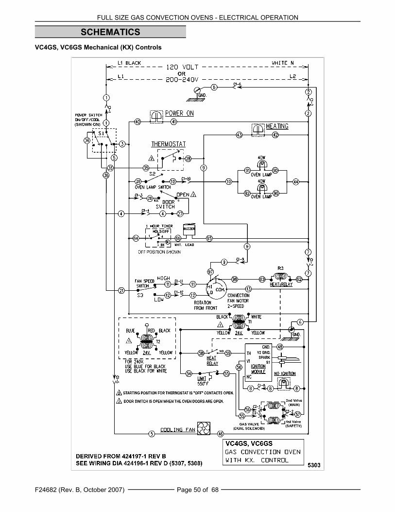
FULL SIZE GAS CONVECTION OVENS - ELECTRICAL OPERATION
F24682 (Rev. B, October 2007) Page 50 of 68
SCHEMATICSVC4GS, VC6GS Mechanical (KX) Controls

FULL SIZE GAS CONVECTION OVENS - ELECTRICAL OPERATION
F24682 (Rev. B, October 2007)Page 51 of 68
VC4GS, VC6GS Mechanical (KX) Controls, Roast & Hold Option

FULL SIZE GAS CONVECTION OVENS - ELECTRICAL OPERATION
F24682 (Rev. B, October 2007) Page 52 of 68
VC4GD, VC6GD Solid State Temperature Control
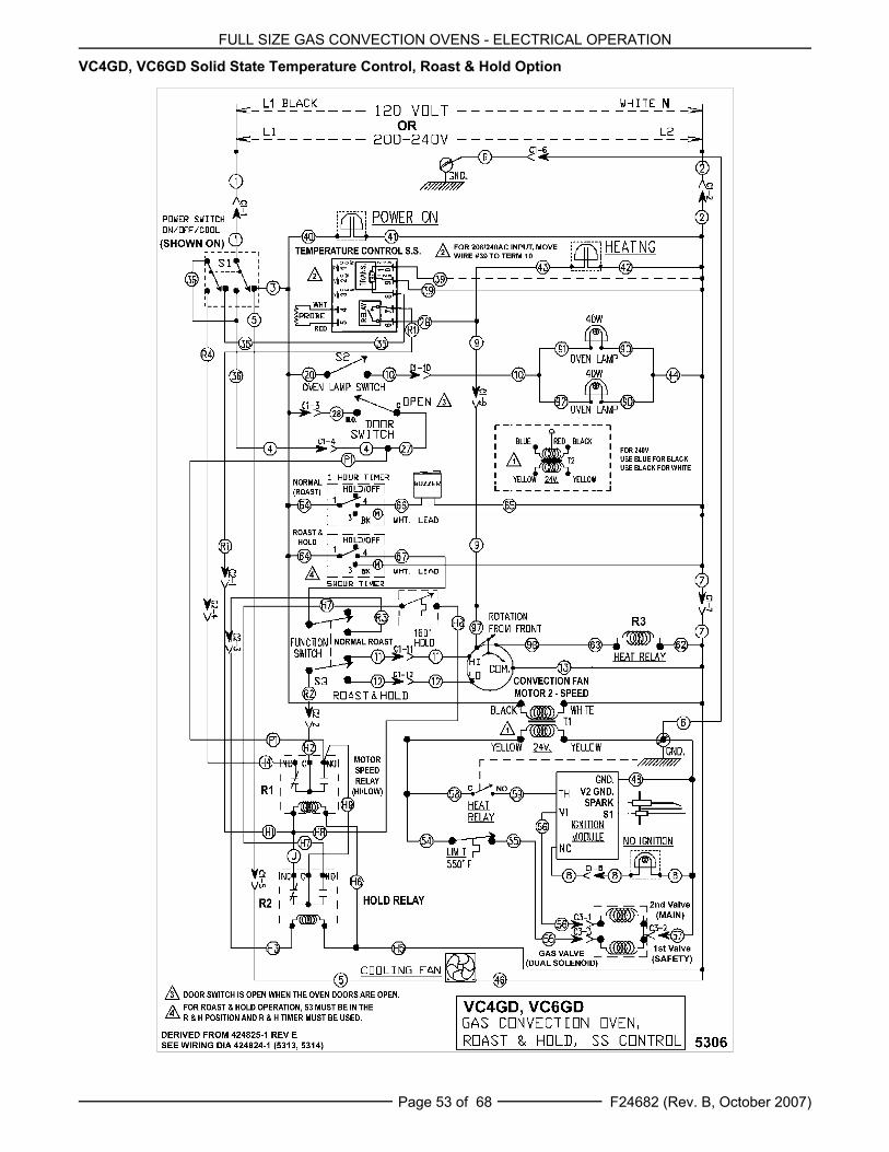
FULL SIZE GAS CONVECTION OVENS - ELECTRICAL OPERATION
F24682 (Rev. B, October 2007)Page 53 of 68
VC4GD, VC6GD Solid State Temperature Control, Roast & Hold Option

FULL SIZE GAS CONVECTION OVENS - ELECTRICAL OPERATION
F24682 (Rev. B, October 2007) Page 54 of 68
VC4GC, VC6GC Computer Control (Roast & Hold Standard)
FULL SIZE GAS CONVECTION OVENS - ELECTRICAL OPERATION
F24682 (Rev. B, October 2007)Page 55 of 68
- N O T E S -

FULL SIZE GAS CONVECTION OVENS - ELECTRICAL OPERATION
F24682 (Rev. B, October 2007) Page 56 of 68
WIRING DIAGRAMSVC4GS, VC6GS Mechanical (KX) Controls
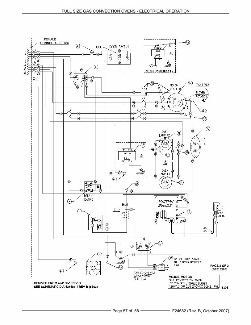
FULL SIZE GAS CONVECTION OVENS - ELECTRICAL OPERATION
F24682 (Rev. B, October 2007)Page 57 of 68
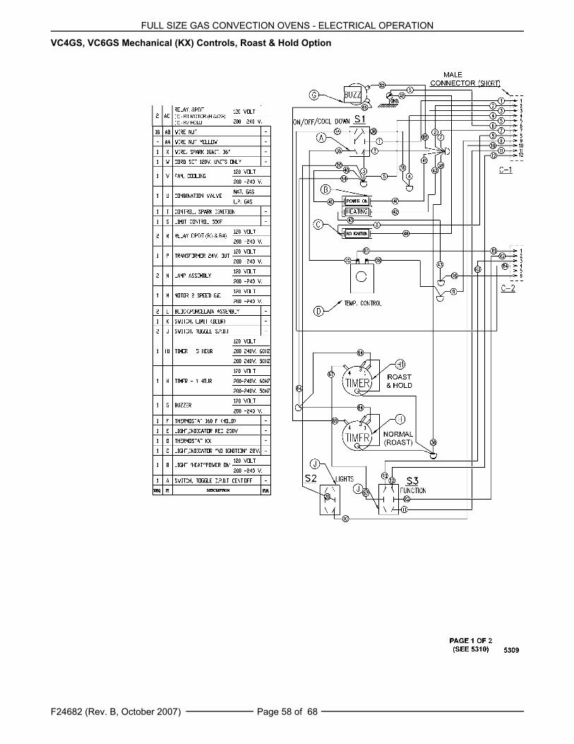
FULL SIZE GAS CONVECTION OVENS - ELECTRICAL OPERATION
F24682 (Rev. B, October 2007) Page 58 of 68
VC4GS, VC6GS Mechanical (KX) Controls, Roast & Hold Option
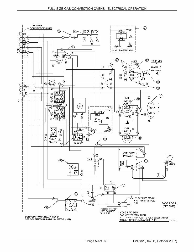
FULL SIZE GAS CONVECTION OVENS - ELECTRICAL OPERATION
F24682 (Rev. B, October 2007)Page 59 of 68
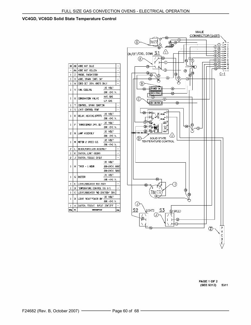
FULL SIZE GAS CONVECTION OVENS - ELECTRICAL OPERATION
F24682 (Rev. B, October 2007) Page 60 of 68
VC4GD, VC6GD Solid State Temperature Control
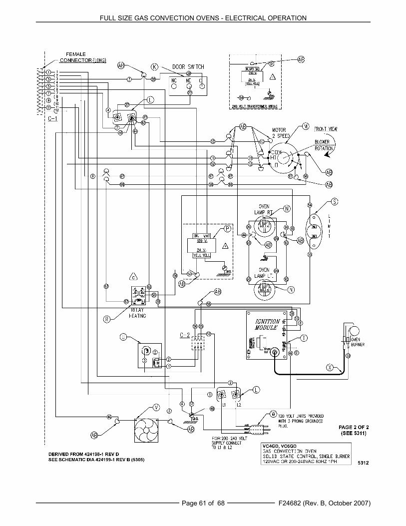
FULL SIZE GAS CONVECTION OVENS - ELECTRICAL OPERATION
F24682 (Rev. B, October 2007)Page 61 of 68
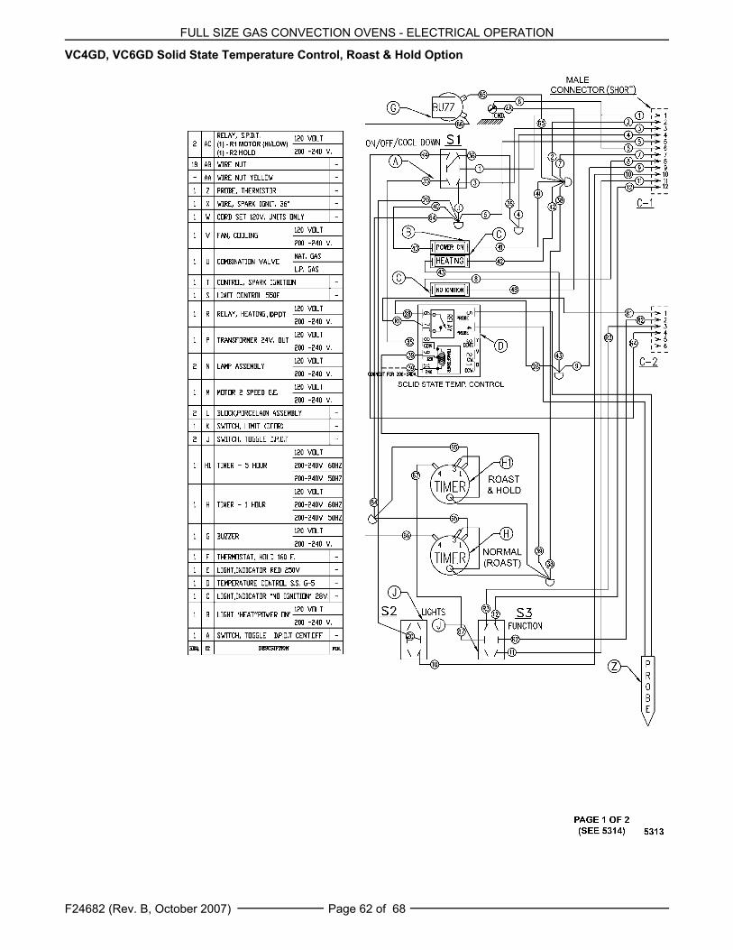
FULL SIZE GAS CONVECTION OVENS - ELECTRICAL OPERATION
F24682 (Rev. B, October 2007) Page 62 of 68
VC4GD, VC6GD Solid State Temperature Control, Roast & Hold Option

FULL SIZE GAS CONVECTION OVENS - ELECTRICAL OPERATION
F24682 (Rev. B, October 2007)Page 63 of 68
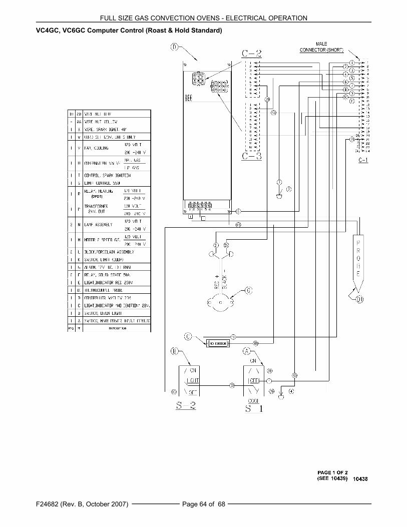
FULL SIZE GAS CONVECTION OVENS - ELECTRICAL OPERATION
F24682 (Rev. B, October 2007) Page 64 of 68
VC4GC, VC6GC Computer Control (Roast & Hold Standard)
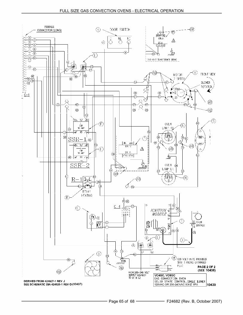
FULL SIZE GAS CONVECTION OVENS - ELECTRICAL OPERATION
F24682 (Rev. B, October 2007)Page 65 of 68

FULL SIZE GAS CONVECTION OVENS - TROUBLESHOOTING
F24682 (Rev. B, October 2007) Page 66 of 68
TROUBLESHOOTING Certain procedures in this section require electrical test or measurements while power is
applied to the machine. Exercise extreme caution at all times. If test points are not easily accessible,disconnect power and follow lockout / tagout procedures, attach test equipment and reapply power totest.
ALL MODELS
SYMPTOMS POSSIBLE CAUSESBlower motor doesn’t run with 1S in COOL DOWN orON position.
1. Line voltage.2. Power switch (S1) malfunction.3. Switch (S3) malfunction.4. Interconnecting wiring malfunction.5. Motor inoperable.
Blower motor doesn’t run in ON position. COOLDOWN functions OK.
1. Door switch malfunction.2. Power switch contacts inoperative.3. Interconnecting wiring malfunction.
Blower motor doesn’t run in COOL DOWN position.Runs OK in ON position.
1. Power switch malfunction.2. Interconnecting wiring malfunction.
Gas does not ignite; No spark; No Ignition Light ON. 1. Shorted electrode on ignitor/flame sense.2. Ignitor cable (high voltage) OPEN.3. Heat relay (R3) malfunction.4. Transformer (T1) inoperative.5. High limit thermostat open.6. Interconnecting wiring malfunction.7. Ignition Module malfunction.
Sparks but gas does not ignite. 1. Gas solenoid valve OFF or inoperative.2. Manual gas valve CLOSED.3. Gas supply OFF or Insufficient gas pressure.4. Interconnecting wiring malfunction.5. Ignition Module malfunction.
Gas ignites but will not maintain flame. 1. Igniter lead connections malfunction.2. Ignitor ground inoperative.3. Ignitor/flame sense malfunction.4. Insufficient gas pressure.5. Snorkel vent plugged, obstructed or missing.6. Incorrect polarity from transformer (T1) to Ignition
module.
Excessive or low heat. 1. Temperature probe malfunction on modelsVC4GD/6GD.(Thermostat malfunction on models VC4GS/6GS)
2. Temperature control board malfunction.3. Gas pressure Insufficient.4. Gas orifice plugged or obstructed.
Mechanical Timer inoperative or not functioningproperly.
1. Interconnecting wiring malfunction.2. Line voltage incorrect.3. Timer malfunction.

FULL SIZE GAS CONVECTION OVENS - TROUBLESHOOTING
F24682 (Rev. B, October 2007)Page 67 of 68
SYMPTOMS POSSIBLE CAUSESNormal (Roast) mode OK, no Hold mode.(Roast & Hold models only).
1. Roast and Hold switch (S3) malfunction.2. R2 hold relay malfunction.3. Roast & Hold timer malfunction.4. Interconnecting wiring malfunction.
Component cooling Fan does not run. 1. Motor inoperable.2. Interconnecting wiring malfunction.
Uneven Cooking. 1. Convection Fan motor speed/direction.2. Poor combustion.
A. Gas pressure incorrect.B. Exhaust vent plugged or obstructed.C. Snorkel Vent plugged or obstructed.
3. Air flow Baffles missing or damaged.
Intermittent problems. 1. High ambient temperatures.2. Wiring connections loose.3. Cooling fan malfunction.
No power to temperature control. 1. Power switch (S1) in COOL DOWN.2. Door or door switch open.
COMPUTER CONTROL MODELS ONLY
SYMPTOM POSSIBLE CAUSESOven does not heat. 1. High limit switch open.
2. Probe malfunction.3. Control malfunction.
High limit thermostat shutting off gasburner.
1. Probe malfunction.2. Control malfunction.
Oven not hot enough. 1. Probe malfunction.2. Control range high (rH1) setting to low. See SETUP MODE
under COMPUTER CONTROL (VC4GD, VC6GD).3. Control malfunction.
Error CodesIn the display window, the error code will alternate between the code and the oven cavity temperature or dashes ifthe oven is calling for heat (heat light on). When the condition causing the error is resolved, normal oven operationcan resume.
NOTE: To check a SETUP PARAMETER and its corresponding DATA VALUE, see SETUP MODE underCOMPUTER CONTROL (VC4GC/6GC).
NOTE: If the cause of the error is not apparent, check for these conditions as they may also cause errors to occur:Electrical noise or a noise event, excess environmental moisture or temperature, or vibration.
CODE & PROBLEM PROBABLE CAUSE SOLUTIONEr01 - ROM checksum error Internal ROM malfunction Cycle powerEr02 - RAM checksum error Internal RAM malfunction Cycle powerEr03 - Ambient sensor error Ambient temperature is below 32EF Check ambient temperature at the
control.Er04 - Configuration error Microprocessor malfunction Cycle powerEr05 - EEprom error Power loss while storing data Cycle power
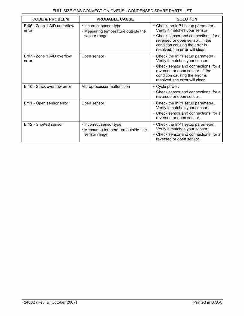
FULL SIZE GAS CONVECTION OVENS - CONDENSED SPARE PARTS LIST
CODE & PROBLEM PROBABLE CAUSE SOLUTION
F24682 (Rev. B, October 2007) Printed in U.S.A.
Er06 - Zone 1 A/D underflowerror
• Incorrect sensor type• Measuring temperature outside the
sensor range
• Check the InP1 setup parameter.Verify it matches your sensor.
• Check sensor and connections for areversed or open sensor. If thecondition causing the error is resolved, the error will clear.
Er07 - Zone 1 A/D overflowerror
Open sensor • Check the InP1 setup parameter.Verify it matches your sensor.
• Check sensor and connections for areversed or open sensor. If thecondition causing the error is resolved, the error will clear.
Er10 - Stack overflow error Microprocessor malfunction • Cycle power.• Check sensor and connections for a
reversed or open sensor.Er11 - Open sensor error Open sensor • Check the InP1 setup parameter.
Verify it matches your sensor.• Check sensor and connections for a
reversed or open sensor.Er12 - Shorted sensor • Incorrect sensor type
• Measuring temperature outside thesensor range
• Check the InP1 setup parameter.Verify it matches your sensor.
• Check sensor and connections for areversed or open sensor.


![整備キット品番変更のお知らせ - Seiken · 2020. 8. 25. · 19,200円 40201-Z5825 400-51602 [4571187476873] 20,700円 40201-Z5928 ・ガスケット:425-00042 → 425-00062](https://img.dokumen.tips/doc/110x75/60ce43c677a9652bb65b91b4/fffcc-seiken-2020-8-25-19200-40201-z5825.jpg)