Embed Size (px)
Citation preview

SERVICE MANUAL Commercial Air Conditioning
5HP fixed frequency free multi
AU422XIBAA
AS122XABAA
AS122XCBAA AE122XCBAA AB122XCBAA AF122XCBAA
AS142XCBAA AE142XCBAA AB142XCBAA AF142XCBAA
AE212XCBAA AB212XCBAA
FeaturesAuto-check functionAuto –restart function (optional )Group control function Weekly timer (optional)Variable Control modesThe total capacity of indoor unit can be more than that of outdoor unit.With new environment friendly refrigerant R407C
HAIER GROUP MANUAL CODE: SYJS-023-03 REV: 2 EDITION: 2005.03
CONTENTS
CONTENTS
Contents1. Description of products & features2. Specification3. Safety precaution4. Net dimension of indoor and outdoor5. Installation instructions6. Parts and functions7. Remote controller functions8. Refrigerant diagram9. Electrical control functions10. Diagnostic information (trouble shooting)11. Electrical data12. Exploded view and parts lists13. Performance curves14. Noise level charts15. Air velocity distribution

1.DESCRIPTION OF PRODUCTS & FEATURES 1.1. Products code explanation A U 42 2 X I B A A
Climate type: T1 (see table 1)
Design number (A stands for design sequence,fixed frequency type) Product type: A stands for heat pump type, refrigerant is R22
B stands for heat pump type, refrigerant is R407C
M stands for cool only type, refrigerant is R22
N stands for cool only type, refrigerant is R407C
Appearance character
Product series: X stands for 1 to 2, 1 to 3, 1 to 4
Applicable voltage: 2 stands for 220-240V/50Hz,
4 stands for 220V/60Hz N stand for 380V/50Hz
Cooling / Heating capacity,42=42000BTU/h
Product type : “B” stands for cassette type, “C” stands for convertible
type, ”D” stands for duct, “S” stands for split type, ”Q” stands for chiller
system, "E" stands for ceiling concealed type, “U” stands for outdoor
unit
Air Conditioner
1.2 Brief Introduction for T1 T2 T3 working condition
1.3 Operating Range of Air Conditioners Temp. Mode Rated Maximum Minimum
DB 27 32 18 IndoorWB 19 23 14 DB 35 43 10
CoolingOutdoor
WB 24 26 6 DB 20 27 15 IndoorWB 14.5 --- -- DB 7 24 -7
HeatingOutdoor
WB 6 18 ---
Climate type Type of Air Conditioner
T1 T2 T3
Cooling Only 18 ~43 10 ~35 21 ~52
Heat pump -7 ~43 -7 ~35 -7 ~52
Electricity Heating ~43 ~35 ~52

1.4 Product character 1.4.1 Operating individually and operating simultaneously The unit can realize individual operation which can control one unit running, stop, and adjusting running mode. Also the unit can operate simultaneously which control multi indoor units at the same time. 1.4.2 Variable quantity of indoor unitIf you want to add or reduce the quantity of indoor units (of course the match must correspond with the design), it can meet your need at any time. More convenient, more random.1.4.3 Universal outdoor unit, multiform indoor unit We realize universal outdoor unit, and 6 kinds of indoor unit, choose freely according to customer’s favor and indoor decoration, more stylish and more beautiful 1.4.4 The total capacity of indoor unit can be more than that of outdoor unit. When all the indoor units are running at the same time, the actual capacity of every indoor unit is proportional according to outdoor capacity. 1.4.5 Long distribution pipe and high drop The distance of outdoor and indoor can be max. 40m, and the drop between indoor and outdoor can be max. up to 25m, consequently, the installation can be more free, and can meet various need of the customer. 1.4.6 Ceiling concealed type unit be equipped with high efficiency filter, and its high static pressure can be up to 30Pa, running more silent, making room air more comfortable and more clean. 1.4.7 Auto-check function The unit can display the malfunction codes on the control board by using advanced auto-check technology ,convenient for user find and dwell with the abnormal running. 1.4.8 Auto –restart function (optional ); All indoor units have auto-restart function. When the power supply cut off suddenly, the unit will automatically recover the previous running mode once the power supply is on. 1.4.9 Group control function 1.4.10 Weekly timer (optional) 1.4.11 Variable Control modes Wired remote control ; Remote control; *Group control: a. With remote monitor function; b. Auto changeover function

—— Cooling Heating
BTU/h 42000 48000
W 12500 14000
W 5600 5600
W 6300 6300
W/W 2.30 2.50
10 ³×m³/h / /
——
——
N, V, Hz
A / A 26.0 / 30.0 26.0 / 30.0
A
A
Model / Manufacture ——
Oil charge and type ——
Type ——
Number ——
Type × Number ——
Speed r/min
Motor output power W
Air-flows (H/M/L) m³/h
Type / Diameter mm
Total area m²
Temp. scope
External mm
Package mm
Drainage pipe material, diameter mm
——
——
——
——
W
Noise level H/M/L dB(A)
Weight Net / Shipping kg / kg
Type / Charge kg
No need to recharge m
Recharge g/m
Liquid mm
Gas mm
——
Drop between IU & OUm
Drop between indoor units m
Piping length m
Total length m
720 CC (RB68AF/T68/ 68TF)
Fuse size (recommended size) 40
5
60/-/-
101/121
Pip
ing
Refrigerant R407C / A:2.2 B:2.45
Piping length less than 5 meters in one way
* Long piping length and large drop between the indoor and outdoor unit (which exceeds standard value) will obviously reduce the capacity.
Connecting method Flared
Between I.D &O.D <=15m(Outdoor unit above indoor )
<=10m(Outdoor unit below Indoor )
15 (per way)
30 (2 ways)
28*2
35
Pipe 6.35
12.7
Type of 4-way valve DPF-6
Refrigerant control method Capillary tube
Defrosting method Automatic
Material of reduce noise XPE
Crankcase heater power
Dimension(L×W×H)
948×340×1250
1050×440×1375
/
850±50/720±50/500±50
60 × 2
6000/4000/3000
Heat exchanger TP2M / 9.52x0.35
about 1.17
cooling: 43~60 / heating: 6~7
Running / Max.Running current
Start current (system A / system B) 55.0 / 55.0
Compressor PG420X3CS-4KU1 / TOSHIBA
Rotary (Fix speed)
2
Fan Axial × 2
Dehumidifying capacity
Power cable 3 × 5.0mm2
Power source 1, 220~230, 50
Communication cable 8x(0.75~1.25mm2 )
Capacity
Total power input
Max. power input
EER or COP
Item Model AU422XIBAAFunction
Capacity
2. SPECIFICATIONS

—— Cooling Heating Cooling HeatingBTU/h 12000 13000 14000 16000
W 3500 3900 4100 460010 ³×m³/h 1.6 / 1.6 /
————
N, V, HzA / A 0.15 0.15 0.15 0.15
Type × Number ——Speed r/minMotor output power WAir-flows (H-M-L) m³/hType / Diameter mmTotal area m²Temp. scopeExternal mmPackage mm
Drainage pipe material, diameter mm————mm——
Noise level H/M/L dB(A)Weight Net / Shipping kg / kgRefrigerant Type ——
Liquid mmGas mm
——
—— Cooling Heating Cooling HeatingBTU/h 12000 13000 14000 16000
W 3500 3900 4100 460010 ³×m³/h 1.6 / 1.6 /
————
N, V, HzA 0.25 0.25 0.25 0.25
Type × Number ——Speed r/minMotor output power WAir-flows (H/M/L) m³/hType / Diameter mmTotal area m²Temp. scopeExternal mmPackage mm
Drainage pipe material, diameter mm————mm——
Noise level H/M/L dB(A)Weight Net / Shipping kg / kgRefrigerant Type ——
Liquid mmGas mm
——
Item Model AS122XCBAA AS142XCBAAFunctionCapacityCapacityDehumidifying capacityPower cable 3 × 0.75mm2
Communication cable 2x(0.75~1.25mm2 )Power source 1, 220~230, 50Running current
Fan CROSS×1
550/500/450
Dimension(L×W×H)
795×197×265
Controller type Phone type infraredRefrigerant control
CROSS×11100/1000/900 1100/1000/900
25 25550/500/450
Heat exchanger TP2M / 6.35×0.7about 0.20 about 0.20
cooling: 6~7 / heating: 43~60795×197×265
880×315×330 880×315×330PVC, 11.4/16.4
Capillary tubeFresh air hole dimension /Electricity Heater /
39/37/30 39/37/307.6/10.6 7.6/10.6
Pipi
ng
R407CPipe 6.35
12.7Connecting method Flared
Item Model AF122XCBAA AF142XCBAAFunctionCapacityCapacityDehumidifying capacityPower cable 3 × 0.75mm2
Communication cable 2x(0.75~1.25mm2 )Power source 1, 220~230, 50Running current
Fan CROSS × 2
700/650/600
Dimension(L×W×H)
720×205×630
Controller type Phone type infrared controllerRefrigerant control
CROSS × 21100/1000/900 1100/1000/900
50 50700/650/600
Heat exchanger TP2M / 7.94×0.35 TP2M / 7.94×0.35about 0.25 about 0.25
cooling: 6~7 / heating: 43~60720×205×630
780×280×690 780×280×690PVC, 11.4/16.4 PVC, 11.4/16.4
Capillary tubeFresh air hole dimension / /Electricity Heater / /
38/36/34 38/36/34
Pipi
ng
R407C R407CPipe 6.35 6.35
12.7 12.7Connecting method Flared Flared
17/20.7 17/20.7

—— Cooling HeatingBTU/h 12000 13000
W 3500 390010 ³×m³/h 1.0 /
——N, V, Hz
A / A 0.25 0.25A
——Type × Number ——Speed r/minMotor output power WAir-flows (H-M-L) m³/hType / Diameter mmTotal area m²Temp. scopeExternal mmPackage mm
Drainage pipe material, diameter mm————mm——
Noise level Distance 1m dB(A)Weight Net / Shipping kg / kgRefrigerant Type ——
Liquid mmGas mm
——
Item Model AS122XABAAFunction
Norminal condition: indoor temperature (cooling): 27 DB/19 WB, indoor temperature (heating): 20 DBOutdoor temperature(cooling): 35 DB/24 WB, outdoor temperature(heating): 7 DB/6 WB
Power sourceRunning current
CapacityCapacityDehumidifying capacityPower cable
1100/920/80055
Start current
Indo
or u
nit
Unit model (color)Fan
Controller typeRefrigerant control
Dimension(L×W×H)
620/510/450Heat exchanger
about 0.20TP2M / 6.35×0.7
cooling: 6~7 / heating: 43~60930×185×265
Pip
ing Pipe
Connecting method
45/38/339.6/12.6
Fresh air hole dimensionElectricity Heater
/AS122XABAA (white)
CROSS×1
3 × 0.75mm21, 220~230, 50
6.3512.7
Flared
1013×277×331
//
R407C
PVC, 11.4/16.4Phone type infrared
Capillary tube

—— Cooling Heating Cooling HeatingBTU/h 12000 13000 14000 16000
W 3500 3900 4100 460010 ³×m³/h 1.6 / 1.6 /
————
N, V, HzA 0.20 0.20 0.20 0.20
Type × Number ——Speed r/minMotor output power WAir-flows (H/M/L) m³/hType / Diameter mmTotal area m²Temp. scopeExternal mmPackage mm
Drainage pipe material, diameter mm————mm——
Noise level H/M/L dB(A)Weight Net / Shipping kg / kgRefrigerant Type ——
Liquid mmGas mm
——External mmPackage mm
Weight Net / Shipping kg / kg* o.d.=outer diameter; i.d.=inner diameter
—— Cooling Heating Cooling HeatingBTU/h 12000 13000 14000 16000
W 3500 3900 4100 460010 ³×m³/h 1.6 / 1.6 /
————
N, V, HzA 1.35 1.35 1.35 1.35
Type × Number ——Speed (SH/H/M/L*) r/minMotor output power WAir-flows (SH/H/M/L*) m³/hType / Diameter mmTotal area m²Temp. scopeExternal mmPackage mm
Drainage pipe material, diameter mm————mm——
Noise level SH/H/M/L* dB(A)Weight Net / Shipping kg / kgRefrigerant Type ——
Liquid mmGas mm
——* SH/H/M/L: Super high/High/Medium/Low, the values are measured in the condition: external static pressure is 0Pa.
Item Model AB122XCBAA AB142XCBAAFunctionCapacityCapacityDehumidifying capacityPower cable 3 × 0.75mm2
Communication cable 2x(0.75~1.25mm2 )Power source 1, 220~230, 50Running current
Fan CENTRIFUGAL × 1
650/580/550
Dimension(L×W×H)
700×570×276
Controller type Phone type infrared controller or Wired controllerRefrigerant control
CENTRIFUGAL × 1750/610/540 750/610/540
40 40650/580/550
Heat exchanger TP2M / 9.52×0.8 TP2M / 9.52×0.8about 0.25 about 0.25
cooling: 6~7 / heating: 43~60700×570×276
775×715×361 775×715×361PVC, 32/26(o.d./I.d.*) PVC, 32/26(o.d./I.d.*)
Capillary tubeFresh air hole dimension 100 100Electricity Heater / /
43/40/37 43/40/3726/28 26/28
Pipi
ng
R407C R407CPipe 6.35 6.35
12.7 12.7Connecting method Flared Flared
Pane
l Dimension 630×630×80 630×630×80680×680×155 680×680×155
4.2/6.3 4.2/6.3
Item Model AE122XCBAA AE142XCBAAFunctionCapacityCapacityDehumidifying capacityPower cable 3 × 0.75mm2
Communication cable 2x(0.75~1.25mm2 )Power source 1, 220~230, 50Running current
Fan AXIAL× 1 AXIAL × 11384/1350/1300/1230 1384/1350/1300/1230
50 501051/1007/985/930 1051/1007/985/930
Heat exchanger TP2M / 9.52×0.8 TP2M / 9.52×0.8about 0.12 about 0.13
cooling: 6~7 / heating: 43~60Dimension(L×H×D)
828*225*450 828*225*450976*288*526 976*288*526
O.D.=20, I.D.=18Controller type Wired controllerRefrigerant control Capillary tubeFresh air hole dimension 100 100Electricity Heater / /
Flared
45/42/40/38 45/42/40/3820/22 20/22
Flared
Pipi
ng
R407C R407CPipe 6.35 6.35
12.7 12.7Connecting method

—— Cooling Heating Cooling HeatingBTU/h 21000 24000 21000 24000
W 6150 7000 6150 700010 ³×m³/h 2.5 / 2.5 /
————
N, V, HzA 1.35 1.35 0.80 0.80
Type × Number ——Speed r/minMotor output power WAir-flows (H/M/L) m³/hType / Diameter mmTotal area m²Temp. scopeExternal mmPackage mm
Drainage pipe material, diameter mm————mm——
Noise level H/M/L dB(A)Weight Net / Shipping kg / kgRefrigerant Type ——
Liquid mmGas mm
——External mmPackage mm
Weight Net / Shipping kg / kg* o.d.=outer diameter; i.d.=inner diameter
Flared
Pan
el Dimension(L×W×H)
/ 950×950×80/ 980×980×100/ 6.0/9.0
Pip
ing
R407C R407CPipe 9.52 9.52
15.88 15.88Connecting method Flared
45/42/40 46/43/4028/32 30/32
100 /Electricity Heater / /
Infrared controllerRefrigerant control Capillary tube Capillary tube
840×840×2401272*288*526 910×910×300
O.D.=20, I.U.=16 PVC, 32/26(o.d./I.d.*)
1200/1000/800Heat exchanger TP2M / 9.52×0.8 TP2M / 9.52×0.8
about 0.20 about 0.30cooling: 6~7 / heating: 43~60
CENTRIFUGAL × 11100/970/790/580 700/590/470
50 30
Running currentFan CENTRIFUGAL × 1
1000/900/720/550
Dimension(L×W×H)
1124×450×225
Controller type Wired controller
Fresh air hole dimension
3 × 0.75mm2
Communication cable 2x(0.75~1.25mm2 )Power source 1, 220~230, 50
CapacityCapacityDehumidifying capacityPower cable
Item Model AE212XCBAA AB212XCBAAFunction

model part number part name characteristic
001A3900153 ambient temp sensor
1.R25=5K ±1%B25/50=3450K±1%2.R25=5K ±1%B25/50=3450K±1%
0010450243 A system coil temp sensor R25=5K ±1%B25/50=3450K±1%
0010450398 A system discharging tempsensor
R80=50K ±3%B25/80=4450K±3%
0010451344 B system discharging tempsensor
R80=50K ±3%B25/80=4450K±3%
0010451343 ambient temp sensor, Bsystem coil temp sensor
R25=5K ±1%B25/50=3450K±1%
0010450243 A system coil temp sensor R25=5K ±1%B25/50=3450K±1%
0010450398 A system discharging tempsensor
R80=50K ±3%B25/80=4450K±3%
0010451344 B system discharging tempsensor
R80=50K ±3%B25/80=4450K±3%
AF- 001A3900059 coil temp sensor
1.R25=10K ±3%B25/50=3700K±3%2.R25=23K ±2.5%B25/50=4200K±3%
AE- 001A3900006 gas pipe temp sensor R25=10K ±3%B25/50=3700K±3%
AB- 001A3900006 gas pipe temp sensor R25=10K ±3%B25/50=3700K±3%
AU282XHBAA
AU422XIBAA
characteristic for sensors

4. Net dimension of indoor and outdoor 4.1 Outdoor unit: AU422XIBAA
screw hole (M10)

4.2 Indoor units Model: AF122XCBAA
Model: AS122XCBAA, AS142XCBAA
783
44
0
225
�
�
�
���� �� � ����� �������
� �
��� ��� ���

a
b
c
Model: WALL MOUNTED TYPE
modelAS122XABAA
a b c
930 185265

Model: AE122XCBAA, AE142XCBAA AE212XCBAA
Model: AB122XCBAA, AB142XCBAA
a
i
ef g
b
c
d
TYPEAE072XCBAA,
a b c d e f g i
770 804 225 225 100615 648 452 225 55 225 125 100
AE122XCBAA,1064 1099 225 55 225 100
Installation dimension: (Unit: mm)
AE092XCBAAAE142XCBAA
AE212XCBAA452452
55 125125
UPDATED

Model: AB212XCBAA
(ceiling hole)

WARNINGCAUTION
WARNINGCAUTION
This system should be applied to places of office, restaurant, residence and the like. Appliaction to inferior
environment such as engineering shop could cause equipment malfunction.
Please entrust installation to either the company which sold you the equipment or to a professional contractor.
Defects from improper installations can be the cause of water leakage, electric shocks and fires.
Execute the installation accurately, based on following the installation manual. Again, improper installations can
result in water leakage, electric shocks and fires.
When a large air-conditioning system is installed to a small room, it is necessary to have a prior planned
countermeasure for the rare case of a refrigerant leakage, to prevent the exceeding of threshold concentration.
In regards to preparing this countermeasure, consult with the company from which you purchased the equipment,
and make the installation accordingly. In the rare event that a refrigerant leakage and exceeding of threshold
concentration does occur,there is the danger of a resultant oxygen deficiency accident.
For installation, confirm that the installation site can sufficiently support heavy weight. When strength is insufficient,
injury can result from a falling of the unit.
Execute the prescribed installation construction to prepare for earthquakes and the strong winds of typhoons and
hurricanes, etc. Improper installations can result in accidents due to a violent falling over of the unit.
For electrical work, please see that a licensed electrician executes the work while following the safety standards
related to electrical equipment, and local regulations as well as the installation instructions, and that only exclusive
use circuits are used.
Insufficient power source circuit capacity and defective installment execution can be the cause of electric shocks and
fires.
Accurately connect wiring using the proper cable, and insure that the external force of the cable is not conducted to
the terminal connection part, through properly securing it. Improper connection or securing can result in heat
generation or fire.
Take care that wiring does not rise upward, and accurately install the lid/service panel. Its improper installation can
also result in heat generation or fire.
WARNING
In either case, important safety related information is indicated, so by all means, properly observe all that is mentioned.After completing the installation, along with confirming that no abnormalities were seen from the operation tests, pleaseexplain operating methods as well as maintenance methods to the user (customer) of this equipment, based on the owner's manual.Moreover, ask the customer to keep this sheet together with the owner's manual.
Please read these "Safety Precautions" first then accurately execute the installation work.Though the precautionary points indicated herein are divided under two headings, and
those points which are related to the strong possibility of an installation done in error resulting in death or serious injury are listed in the section. However, there is also a possibility of serious consequences in relationship to the points listed in the section as well.
- 10 -
SAFETY PRECAUTIONS
3 SAFETY PRECAUTIONS

When setting up or moving the location of the air conditioner, do not mix air etc. or anything other than the designated
refrigerant (please see nameplate) within the refrigeration cycle.
Rupture and injury caused by abnormal high pressure can result from such mixing.
Always use accessory parts and authorized parts for installation construction. Using parts not authorized by this
company can result in water leakage, electric shock, fire and refigerant leakage.
The position of indoor unit must be above the floor 2.5m.
WARNING
Execute proper grounding. Do not connect the ground wire to a gas pipe, water pipe, lightening rod or a telephone
ground wire.
Improper placement of ground wires can result in electric shock.
The installation of an earth leakage breaker is necessary depending on the established location of the unit. Not
installing an earth leakage breaker may result in electric shock.
Do not install the unit where there is a concern about leakage of combustible gas.
The rare event of leaked gas collecting around the unit could result in an outbreak of fire.
For the drain pipe, follow the installation manual to insure that it allows proper drainage and thermally insulate it to
prevent condensation. Inadequate plumbing can result in water leakage and water damage to interior items.
CAUTION
- 11 -
SAFETY PRECAUTIONS

The unit capacity and performance mode: (A stands for system A, B stands for system B) Performance data of combination “AU422XIBAA+122X*BAA 4” as followings:
Performance mode
A:
AF122*1
AS122*1
AB122*1
AE122*1
B:
AF122*1
AS122*1
AB122*1
AE122*1
A:
AF122*2
AS122*2
AB122*2
AE122*2
B:
AF122*2
AS122*2
AB122*2
AE122*2
A:
AF122*2
AS122*2
AB122*2
AE122*2
B:
AF122*2
AS122*2
AB122*2
AE122*2
Nominal capacity W 3800 3800 6250 6250 12500 Rated power input W 2200 2200 2350 2350 4700 cooling
Rated current A 11.0 11.0 11.5 11.5 23.0 Nominal capacity W 4500 4500 7000 7000 14000 Rated power input W 2600 2600 2300 2300 4600 heating
Rated current A 13.0 13.0 11.5 11.5 23.0
Must pay special attention to the match style, to see the following table:
1 to 2 1 to 3 A B A B
AE212XCBAA*1 AE212XCBAA*1 AE212XCBAA*1 AF122XCBAA×2 AF142XCBAA×2
AB212XCBAA*1 AB212XCBAA*1 AB212XCBAA*1 AS122XCBAA×2 AS142XCBAA×2
AB122XCBAA×2 AB142XCBAA×2
AE122XCBAA×2 AE142XCBAA×2
AS122XABAA×2
1 to 4 A B
AF122XCBAA×2 AF142XCBAA×2 AF122XCBAA×2 AF142XCBAA×2
AS122XCBAA×2 AS142XCBAA×2 AS122XCBAA×2 AS142XCBAA×2
AB122XCBAA×2 AB142XCBAA×2 AB122XCBAA×2 AB142XCBAA×2
AE122XCBAA×2 AE142XCBAA×2 AE122XCBAA×2 AE142XCBAA×2
AS122XABAA×2 AS122XABAA×2

Pipe connections:
1 TO 4
A1
A2
B1
B2
B2A1 A2 B1
Outdoor unit
Indoor units
1 TO 3(except for 21000BTU/h units)
A1
A2
B1
B2
Outdoor unit
Indoor units
A2 B1 B2
1 TO 2(except for 21000BTU/h units)
A1
A2
B1
B2
Outdoor unit
Indoor units
A2 B2
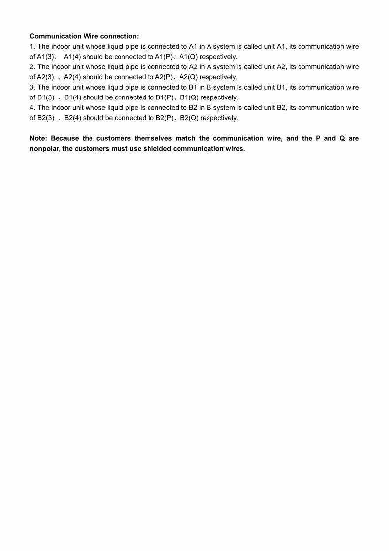
Communication Wire connection: 1. The indoor unit whose liquid pipe is connected to A1 in A system is called unit A1, its communication wire of A1(3) A1(4) should be connected to A1(P) A1(Q) respectively. 2. The indoor unit whose liquid pipe is connected to A2 in A system is called unit A2, its communication wire of A2(3) A2(4) should be connected to A2(P) A2(Q) respectively. 3. The indoor unit whose liquid pipe is connected to B1 in B system is called unit B1, its communication wire of B1(3) B1(4) should be connected to B1(P) B1(Q) respectively. 4. The indoor unit whose liquid pipe is connected to B2 in B system is called unit B2, its communication wire of B2(3) B2(4) should be connected to B2(P) B2(Q) respectively.
Note: Because the customers themselves match the communication wire, and the P and Q are nonpolar, the customers must use shielded communication wires.

Special Installation Guide to 21000BTU indoor units on Free Multi system Only for outdoor unit AU422XIBAA working with 21000BTU indoor units
1. Special accessory pipes for 21000BTU indoor units: A B
Changing pipe (1/2-5/8) Collecting pipe (1/4-3/8)
12.7 15.88
6.35 9.52
6.35
2. Pipe installations:
A1
A2
B1
B2
Gas pipe 15.88Liquid pipe 9.52
Liquid pipe 9.52Gas pipe 15.88
21000BTU indoor unit
21000BTU indoor unit
3. Outdoor wiring diagram should be changed as the following:
Coil of solenoid vavle A2 should be changed to connected with CN29.Coil of solenoid vavle B2 should be changed to connected with CN23.By-pass vavle on both system A and system B should be pulled out and not connected.
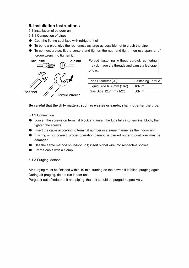
5. Installation instructions 5.1 Installation of outdoor unit 5.1.1 Connection of pipes
Coat the flaring seal face with refrigerant oil. To bend a pipe, give the roundness as large as possible not to crash the pipe. To connect a pipe, fit the centers and tighten the nut hand tight, then use spanner of torque wrench to tighten it.
Forced fastening without careful, centering may damage the threads and cause a leakage of gas.
Be careful that the dirty matters, such as wastes or sands, shall not enter the pipe.
5.1.2 Connection Loosen the screws on terminal block and insert the lugs fully into terminal block, then tighten the screws. Insert the cable according to terminal number in a same manner as the indoor unit. If wiring is not correct, proper operation cannot be carried out and controller may be damaged.Use the same method on indoor unit; insert signal wire into respective socket. Fix the cable with a clamp.
5.1.3 Purging Method
Air purging must be finished within 10 min, turning on the power, if it failed, purging again. During air pruging, do not run indoor unit. Purge air out of indoor unit and piping, the unit should be purged respectively.
Pipe Diameter ( ) Fastening TorqueLiquid Side 6.35mm (1/4”) 18N.m Gas Side 12.7mm (1/2”) 50N.m


Place where it is easy to route drainage pipeand outdoor piping.Place ,away from heat source and with lessdirect sunlight.Place where cool and warm air could bedelivered evently to every corner of the room.Place near power supply socket.Leave enoughspace around the unit.Place ,robust not causing vibration,where thebody can be supported sufficiently.To prevent interference, place it at least 1maway from other electric machines, such asTV set, radio.InstallingAccording to the dimension of the figure 2 shown,nail two cement steel nails on the wall,Keep 2~3mm out.then hang the back of the unit on them.There must be no gap between the indoor unitand wall.Remove the front panel,then use two expansiblescrews to fix the unit on the floor.As figure 3shown.Once refrigerant piping and drain piping connectionsare complete,fill the gap of the throght hole with putty.Attach the front panel and front grille in their orginalpositions once all connections are complete.
Tool necessary1. Screw driver2. Hacksaw3. 70mm dia.hole core drill4. Spanner(dia. 17,27mm)5. Spanner(14,17,27mm)6. Pipe cutter7. Flaring tool8. Knife9. Nipper10. Gas leakage detector or soap water11. Measuring tape12. Reamer13. Refrigerant oilStandard accessoriesFollowing parts shall be field supplied
Note: There isn't connecting wire with this unit.
No. Shape and description QTY
Remote controller
Wire clip
Self-tapping screw
Dry battery #7
Wall hole cover
Cement steel nail 6
Installation of indoor unitselection of installation place
Fig1
Mark Part nameAdhensive tapePipe clipConnecting hoseInsulation materialPuttyDrain hose
ABCDEF
330
617
Fig2
Fig3
more than
more than
more than
mor
e th
an
5.2 Installation of indoor unit for console type

Fixing of the unit1.Position of the wall hole Wall hole should be decided according to installation place and piping direction.(refer to installation drawings).
2. Making a wall hole Drill a hole of 120X70mm dia. with a little slope towards outside.3. Piping connection
Indoor side Outdoor side
Thicknessof wall
Wall hole
70mm
(Cross section of wall hole)
Threads on the pipes may be damagedwhen tightening if the pipes are notwell aligned.
(1)Schematic diagram for unit connection
(4) Pipe connection process
Torque
18 N.m
Pipe Value
6.35mmLiquid50 N.m
(2) Connection pipe dimensions:
12.7mmGaseous
Outdoor uint
Gaseous pipe
Liquid pipe
3-way Valve
2-way ValveFlared pipe connection
Flared pipe connection
Indoor unit
Indoor unit
Manifold tube
Apply and tighten the nut.
(3)Maximum length and height difference of connecting pipe
Maximum length: 20m; Height difference: 10m To ensure efficiency, shortest possible pipe should be used.
Cautions for pipe connection Pipes free from twists, deformation, water, dust. Dedicated tools for each R407C and R22 should be used and stored separately. Optimized radii of bends Insulation to be applied on all gaseous pipes Flared section free from cracks
JointSpanner
SpannerNut
Apply refrigeration oil on the end of the pipe to be connected and on the flared section.Align the pipes to be connected and tighten the nut. (See the figure)Ensure that no foreign articles enter into the pipes.

Piping connection of the indoor unit1. Arrangement of piping and drainage pipe After opening inlet grill,you will see a control box. Remove the cover before working.
Cut away, with a hammer or a saw, the lid for piping according to piping direction.
According to the piping method, connect the piping on indoor unit with union of connection pipe.Arrange the piping as per the wall hole and bind drain hose connecting electric cable and pipingtogether with polyethylene tape.Insert the bound piping connecting electric cable and drain hoes through wall hole to connectwith outdoor unit.
2. Arrangement drain hoseDrain hose shall be placed in under place.There should be a slope when arrange drain hose. Avoid up and down waves in drain hose.If humidity is high, drain pipe(especially in room and indoor unit) must be covered withinstallation material.
Insulation material
Copper tube
Drain hose
Connecting electric cablefor indoor and outdoor unit
Electric wiring :Process of wire connections
1. Loop terminal After removing the screw, fix the wire ring on the screw, reinsert the screw into the block terminal and then tighten the screw.
2. Straight terminal After loosening the screw, inset the wire end into the block terminal and then tighten the screw. Slightly pull the wire to see if it is tightly fixed.
3. Wire capping After completion of connection, capping clips must be applied on the external sleeve of the wires.
Wiring diagram:
Wiring of indoor unit
Remove air intake screen and take out the front wires. Connect the wires as specified in the above
methods and diagrams for indoor unit and wire con- nections.
Properly apply capping clips on the wires. Replace the air intake screen. Do not link the connecting and signal wire with the
same cable, a snug space must be maintained between connecting and signal wires. Shield of the signal wire should be spot grounded.
Block terminal
Capping clip
Wiring diagram of loop terminals
1(L)

When connecting indoor and outdoor wire, check the number on indoor and outdoor terminalblocks. Terminals of same number and same color shall be connected by the same wire.Incorrect wiring may damage air conditioner's control or cause operation failure.
Note:
Wiring diagram:
W:WHITEB:BLACKY/G:YELLOW/GREENR:RED
NOTE:
Block terminalsfor indoor unit
Block terminals for outdoor unit(different outdoorunit have different block terminals)
N L C1 C2
W B Y/G RR
N L C1
W B Y/G RR
C2
2.Piping cutting and flaringBe sure to carry out deburring after cutting with a pipe cutter.Insert flaring tool to make a flare.
Liquid pipePipe diameter Size A (mm)
0.8 ~1.51.2 ~2.0
6.35mm(1/4")12.7mm(1/2")Gas pipe
A
Correct Incorrect
Lean Damage of flare Crack Partial Too outside
Flare tooling die
Others
The power plug should be connected as follows: L for live line, N for neutral line and for grounding.
Voltage: single-phase1PH,220-230V*,50Hz
The power source must be grounded.
Connection parameters: H05RN-F 3G(1.0-1.5)mmSignal parameters:
1.Power supply requirements:
Cables for power supply, connection and signals are prepared by the owner.
Electrical cables should be connected by ìYî method. Damaged or wornelectrical cablemust be replaced by authorized after sales agents.
A circuit breaker must be installed
Dedicated electrical cable should be installed by a qualified technician inaccordance with the state regulation for electrical engineering.
H05RN-F2X(0.75-1.5)mm (Shieded wire)

5.3 Installation Instructions of wall mounted type
Installation Tools1) Screw Driver 2) Hacksaw 3) Hole core drill 4) Hexagon wrench (5mm) 5) Spanner (14,17,19 and 24mm)
6) Torque wrench (17,22,24mm) 7) Pipe cutter 8) Flaring tool
Standard AccessoriesThe standard accessories includes: 1) Measuring type 2) Reamer 3) Refrigerant oil 4) Gas leakage
detector or soap-and-water solution 5) Knife 6) Nipper
Number of articles NO. Accessory Parts 3 by 1 4 by 1
1 1 1
2 1 1
3 1 1
4 1 1
5 6 8
6 24 32
7 6 8
8 18 24
9 6 8
10 6 8
11 3 4
12 1 1
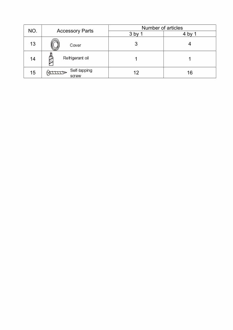
Number of articles NO. Accessory Parts 3 by 1 4 by 1
13 3 4
14 1 1
15 12 16

1 Fitting of the Mounting plate and Positioning of the Wall Hole
1 Carry out,based on the neighboring pillars or lintels, a proper leveling for the plate to be fixed against the
wall,then temporarily fasten the plate with one steel nail.
2 Make sure once more the proper level of the plate,by hanging a thread with a weight from the central top
of the plate,then fasten securely the plate with the attachment steel nail.
3 Find the wall hole location A using a measuring tape.
Holes for fixing the mounting plate
1 Stick a paper pattern on the wall horizontally2 Position by using the pattern then remove the pattern.
lndoor side Outdoor side
Thicknessof wall
wall hole
B mm
When the mounting plate is fixed to side bar and lintel
(Section of wall hole) Piping hole pipe
Fix to side bar and lintel a mounting bar, which is separately sold,and then fasten the plate to the fixed
mounting bar.
Refer to the previous article," ",for the position of wall hole.
When the mounting plate is first fixed
Fit the level line
When the paper pattern is used
Make a hole of 60mm in diameter, slightly descending to outside the walllnstall piping hole cover and seal off with putty after installation.
2 Making Hole on the Wall and Fitting the Piping Hole Cover
When the mounting plate is first fixed
WeightThread
AMountingPlate
Fit the scale to a line
Center of a Bmm hole
(insert a scale)
Outline of mounting plate
Outline of indoor unit
Position of Bmm hole
Paper pattern
Indoor Unit The installation of wall mounted type

3 lnstallation of the lndoor Unit
Drawing of pipe
[Rear piping]
Draw pipes and the drain hose, then fasten them and connecting electric cable for indoor and outdoor with
the adhesive tape.
Drain hose should be placed under.
Right pipingLeft piping
Under piping
Adhesive tapeB
Heat insulationmaterial
Drain hose
Piping
Pipe supportingplate
Indoor/OutdoorElectric cable
[Other direction piping]
[Installation of piping support plate]
[Cautions]
Cut away, the left, under or right side lid with a nipper or saw, according to the wall hole position, then bend the piping and fix it with piping support plate.Sometimes it becomes an easy installation by preconnecting the interconnect cable,then fasten piping and drain hose with it .
Insert the plate from top, into the piping to be fixed.
Push its buttom hard until you hear a clik.
1. Make sure it is unit A or unit B, when make wiring.2. Unit to be connected to stop valve A on outdoor unit is unit A, while the one to be connected to stop valve B is unit B.3. Refer to wiring diagram.
Fixing the indoor unit body
Hang surely the unit body onto the upper notches of the mounting
plate.Move the body from side to side to verify its secure fixing.
ln order to fix the body onto the mounting plate, hold up the body
aslant from the under side and then put it down perpendicularly.
4 Connecting the lndoor/Outdoor Electric Cable
Removing the wiring cover
Open the inlet grill ,then remove one screw of the cover.
Click
Pipe supportingplate
Inlet grill
Wiring cover
Screw
H
G
Putty
Piping hole cover

5.4 Installation of ceiling concealed typeInstallation of indoor unit
Each air return and supply duct should fix to the floor precast slab by using an iron stand. Use glue toseal the interface closely. Recommend the distance between the air return duct and the wall is more than150mm.
The distance between air duct outlet and air conditioner outlet is according to the length of actually installedair duct and in service behavior of the static pressure terminal: Installation sketch map for long and short airduct is showed below, when connect to short air duct, using low static terminal (terminal color is write), thedistance between air duct outlet and air conditioner outlet is no more than 0.5m; when connect to long air duct,using middle static terminal (terminal color is red), the distance between air duct outlet and air conditioner outletcould be within 5m at this point.
When installing the ceiling concealed type indoor unit, a specially designed return airbellows shall be installed, as shown in Figure 3, Figure 4.
A
Installing building roof
Ceiling
Air supply Air outlet duct
Unit
Return airReturn air bellows
Figure 3
Detail A
Figure 5
M8 broad foundation bolt
M8 suspension screw
M8 broad lock ringM8 nut
Unit
Air outlet grille
Air supplyNo obstacleswithin 1 m Unit
Return air
Return air bellows
*0.5m or*5m
As figure shown, suspend and install the unit.
Drain piping of condensed water should keep a downhill grade of 1% or more. Use insulating pipe to coverthe drain piping of condensed water to keep warmth.
Figure 4
air return shutter
air return duct
sling dogdrain piping
transition air duct
air outletduct air diffuser
joint of air diffuser
Figure 5
Figure 6
Installation for air duct of indoor unit1. Installation for air supply duct
This type of unit uses circular air duct with its caliber of 180mm. An additional transitive air duct is necessary for the circular air duct to connect to the air
supply inlet. It should be also connected to its respective air diffuser separately. See Fig.1. Adjust the wind speed of each air diffuser outlet to keep in line on the whole, so as to meet a demand of the air conditioner in the room.

Indoor unit flexible jointor static pressure box
transitive air ductcircular air duct
joint of air diffuser
air diffuser
Fig1: Duct connected
indoor unitair returnshutter
rivet
air returnduct
galvanizedboard
glue nail
insulatingfabric tinfoil
adhesive tapeglue nail cover
2. Installation for air return duct Use rivets to connect the air return duct to the air return inlet of the indoor unit. The other end connects to the air return shutter. as shown in Fig.2.
Fig2: Duct return connected
3. Air duct insulation Insulation layer is needed for air supply and return duct. First, paste a glue nail to the air duct, and then attach the insulation cotton that has a tinfoil layer and use the glue nail cover to fix. Finally, seal the air duct interface with tinfoil adhesive tape closely. as shown in Fig3.
Installing the suspension screw:
Use M8 or M10 suspension screws (4, prepared in the field) (when the suspension screwheight exceeds 0.9 m, M10 size is the only choice). These screws shall be installed asfollows with space adapting to air conditioner overall dimensions according to the originalbuilding structures.
Wooden structure
A square wood shall be supported by the beams and then set the suspension screws.
Square wood
Suspensionscrew
Beam
New concrete slab
To set with embedded parts, foundation bolts etc.

Iron reinforcement
Knife embedded part
Foundation bolt
Guide plate embedded part Pipe suspension foundation bolt
Original concrete slab
Use hole hinge, hole plunger or hole bolt.
Steel reinforcement structure
Use steel angle or new support steel angle directly. Hanging bolt
Suspension screw Support steel angle
Hanging of the indoor unit
l Fasten the nut on the suspension screw and then hang the suspension screw in the T slot of the suspension part of the unit.l Aided with a level meter, adjust level of the unit within 5 mm.

Installation of remote controller
5. Replace the upper cover of wire controller
NoteTry as far as possible a flat surface for installation.Don't use excessive force when tightening screws,or lower part might got deformed.
PCB is mounted on lower part of wirecontroller, be careful not to damage it.
Hint 1. Power supply switch and signal wire should be prepaired by the user.2. Don't touch PCB with hand.
Be careful not to hold down the wiring.
1. Remove upper cover of wire controllerRemove upper part of wire controllerby press.
Lower cover of wirecontroller
Upper cover of wirecontroller
2. Install the wired remote controllerPlease drill two holes on the wall according to theback cover screw hole position of the wire remote controller, then strike the wood block to the holesrespectively, then align the 2 screw hole of the wirecontroller back cover to the wood block, fasten thewire reote controller to the wall use wood screws.3. Switch setting
The switchs setting as follows:1.ON 2.OFF 3.ON 4.OFF
4. Connecting method as the following chart
Switch button
Screw hole
Back cover of the wirecontroller
Use shielede wires for telecommunicationbetween wire controller and indoor unit;indoor unit and outdoor unit. Ground theshield on one side.Otherwise misoperation because of noisemay occur.Signal wire is self-provided by user.
Shielded wire
ground
No Symbol colour contents
1
2
3
4
A
B
C
D
White or Green
Red
Yellow COM
Gnd
12V
Drain pipe
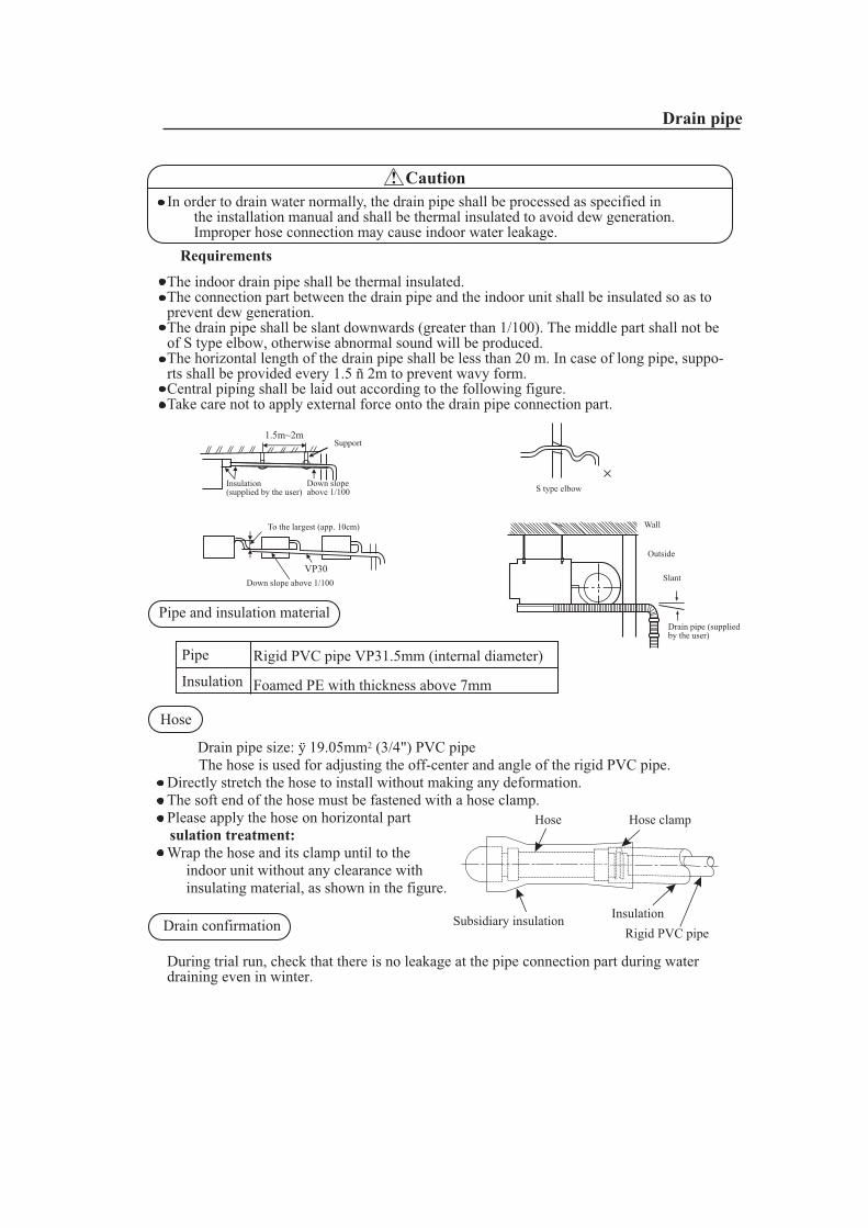
! CautionIn order to drain water normally, the drain pipe shall be processed as specified in the installation manual and shall be thermal insulated to avoid dew generation. Improper hose connection may cause indoor water leakage.
Requirements
The indoor drain pipe shall be thermal insulated.The connection part between the drain pipe and the indoor unit shall be insulated so as toprevent dew generation.The drain pipe shall be slant downwards (greater than 1/100). The middle part shall not beof S type elbow, otherwise abnormal sound will be produced.The horizontal length of the drain pipe shall be less than 20 m. In case of long pipe, suppo-rts shall be provided every 1.5 ñ 2m to prevent wavy form.Central piping shall be laid out according to the following figure.Take care not to apply external force onto the drain pipe connection part.
Pipe and insulation material
Rigid PVC pipe VP31.5mm (internal diameter)
Foamed PE with thickness above 7mm
Pipe
Insulation
Hose
Drain pipe size: ÿ 19.05mm2 (3/4") PVC pipeThe hose is used for adjusting the off-center and angle of the rigid PVC pipe.
Directly stretch the hose to install without making any deformation.The soft end of the hose must be fastened with a hose clamp.Please apply the hose on horizontal partsulation treatment:Wrap the hose and its clamp until to the indoor unit without any clearance with insulating material, as shown in the figure.
Drain confirmation
During trial run, check that there is no leakage at the pipe connection part during waterdraining even in winter.
Hose Hose clamp
Subsidiary insulation InsulationRigid PVC pipe
Wall
Outside
Slant
Drain pipe (suppliedby the user)
VP30
To the largest (app. 10cm)
Down slope above 1/100
S type elbow
1.5m~2mSupport
Insulation(supplied by the user)
Down slopeabove 1/100

Supplementary refrigerant
The refrigerant supplementation shall be as specified in the installation instructions attached with the outdoor unit. The added refrigerant shall be R22.The adding procedure shall be aided with a measuring meterfor a specified amount of supplemented refrigerant
RequirementOverfilling or underfilling of refrigerant will cause compressorfault. The amount of the added refrigerant shall be as specifiedin the instructions.
Connection of refrigerant pipe
The connection of indoor unit pipes must use double spanners.The installing torque shall be as given in the following table.
Double-spanneroperation
Connecting pipeO.D.(mm)
6.359.5212.7015.88
Installing torque(N-m)
11.8 (1.2kgf-m)24.5 (2.5kgf-m)49.0 (5.0 kgf-m)78.4 (8.0 kgf-m)
Increased installingtorque (N-m)
13.7 (1.4 kgf-m)29.4 (3.0 kgf-m)53.9 (5.5 kgf-m)
98.0 (10.0 kgf-m)
Conduct flared connection work toconnect all refrigerant pipes.
Pipe cutting and expandingIf the pipe is too long or the flare is damaged,it needs to be cut or expanded.
Pipe expander
Pipe expansion dimensions as follows:
6.35 mm (1/4") 0.8 ~ 1.59.52 mm (3/8") 1.0 ~ 1.812.7 mm (1/2") 1.2 ~ 2.015.88 mm (5/8") 1.4 ~2.2
Pipe diameter ÿ Size A (mm)
A
Allowable pipe length and drop
These parameters differ according to the outdoor unit. See the instruction manual attachedwith the outdoor unit for details.
Pipe material and size
Pipe material
Model
Phosphorus deoxidized copper seamless pipe (TP2M) for air conditioner
Pipe size(mm)
AE122XCBAA
Gas side 12.7Liquid side 6.35
AE142XCBAA
12.76.35
Refrigerant pipingInstallation Procedure
AE212XCBAA
15.889.52
1. Pipe cutting 2. Removing burrs
3.Insertion nut 4. Pipe expansion
Slope Damage Bur Partial Overlong
Correct Incorrect

Refrigerant piping
Vacuum pumping
With a vacuum pump, create vacuum from the stop valve of the outdoor unit. l Emptying with refrigerant sealed in the outdoor unit is absolutely forbidden.
Open all valves
Open all the valves on the outdoor unit.
Gas leakage detection
Check with a leakage detector or soap water that if there is gas leakage at the pipeconnections and bonnets.
Insulation treatment
Conduct insulation treatment on both the gas side and liquid side of pipes respectively.During cooling operation, both the liquid and gas sides are cold and thus shall be insulated so as to avoid dew generation.
l The insulating material at gas side shall be resistant to a temperature above 120*. l The indoor unit pipe connection part shall be insulated.
The notch upward (Attached detail view)
Indoor unitSubsidiary insulation tube
Field piping side
Installation Procedure

Electric wiring
The electric wiring work shall be conducted by qualified electricians according to the installationinstructions. A separate power circuit shall be used. Insufficient power cord amperage or improperwiring will cause danger of electric shock or fire.During wiring connection, the power cord shall be of the specified cable and reliably fastenedso that external forces applied to the cable wouldnt transfer to the terminals. Improper connectionor fastening will cause danger of heating, fire etc.The power cord must be fitted with a groundingwire.Grounding shall be made as specified. Unreliable grounding will cause electric shock. Thegrounding wire shall not be connected to the gas pipeline, water pipeline, thunder arrestor andtelephone wire
! Caution
A current leakage breaker shall be installed, otherwise it electric shock would happen easily.If the power cord is damaged, it must be replaced by the manufacturer or its service center orsimilar personnel to avoid risks. The power supply to the indoor unit shall be laid in complyingwith the operational instruction manual.The electric wiring shall avoid contacting with the high temperature part of the piping so as toprevent the cable insulation melts and cause dangers.After connected on the terminal block, the wires shall be bent to U form and then fastened withwire clip.The control wiring and refrigerant piping may be laid and fastened together.Before completion of vacuum pumping of the refrigerant pipe system, do not electrify the indoorunit.The power cord of the indoor unit and connection wiring between indoor and outdoor unitsshall be laid out according to the operational instruction manual of the indoor unit.The connection of the power cord shall comply with the local regulations.
!
!
3) Clamping method of the connection wireAfter wire connection is finished, the connection wire must be pressed tightly with wire clips,which shall apply to the outer sheath of the connection wire.
! Warning
The power supply wiring connection should meet the local regulation.
Wiring connection method : (the wiring diagram is attached inside the machine)1) Ring terminal connection methodIf there is a ring at the end of the connection wire,the wire connection method is as shown in the rightfigure. Remove the terminal screw and insert itthrough the ring at the connection wire end, thenconnect to the terminal board and fasten the screw.2) Straight terminal connection methodIf there isnt a ring at the end of the connection wire,the connection method shall be: loosen the terminalscrew, insert the connection wire end completely into the terminal board and fasten the screw.Pull the connection wire outwards slightly to confirm it is clamped tightly.
Connection methodfor ring terminal
Installation Procedure

Wire connection for built-in indoor unitInsert from outside the connection wire and signal transmission wire through the wall holewith pipeline already arranged.Pull out the front ends of connection wire and signal wire and make a circle on the signalwire.Connect the connection wire according to the connection method and indoor and outdoorwiring diagram.Pull the connecting conductor outwards slightly to confirm it is clamped tightly.Connect the plug for connecting the signal wire with the plug of the signal wire connectedfrom the indoor unit.After wire connection is finished, install wire clips using the same method for connectionwire clamping.Note: When connecting the indoor unit and the outdoor unit, please do connect the wireswith the same color terminals.
Notes:Before connecting the conductors between indoor unit and outdoor unit, check for the numberon the indoor and outdoor units connecting terminals. Connect the terminals with the samecolor and number with a wire.Wrong connection would damage the controller of the air conditioner or the machine couldntoperate.Do not connect the connection wire and signal wire with the same cable. They shall beconnected respectively to ensure system normal operation.

5.5 Installation of cassette type (AB122~AB142XCBAA)


1.BEFORE INSTALLATION Do not discard any accessories until installation completed● Determine the best way to carry the unit to its installation place.● Do not remove the packing until the unit reaches the installation place.
2.SELECTION OF INSTALLATION POSITION(1) Installation place shall meet the following and be agreed with the customers/user:● Place where proper air flow can be ensured.● do not restrict air flow.● Water drainage is smooth.● Mounting point strong enough to support unit weight.● Position where inclination is not evident on ceiling.● There is enough space for maintenance.● Indoor and outdoor unit piping length is within limit. (See page 35)● Indoor and outdoor unit, power cable, inter unit cable are at least 1 m away fromT.V. radio. This is necessary to avoid picture disturbance and noise.(2) Ceiling heightThe Indoor unit can be installed in a ceiling of 2.5-3m in height. (Refer to section 9. Setting andInstallation of ornament panel.)(3) Install suspending bolt. Check if the installation is strong enough to hold the unit weight. Takenecessary measures in case it is not safe. (Distance between holes are marked on the paper pattern,Refer to paper pattern for positions needed to be reinforced)
Installation space
260
260
Air inletAir outlet
2500
Ove
r
Air outlet1500 Over1500 Over 1500 Over 1500 Over
Air outletAir inlet
Air inlet
890(Ceiling opening)(Distance between suspending bolts)1070
515
51
(Dist
ance
betw
een
susp
endi
ng b
olts)
860(
Cei
ling
open
ing)
780
A
950(
Bez
el)
890(
Cei
ling
open
ing)
840(
Indo
or u
nit)
780
(Dist
ance
bet
wee
n su
spen
ding
bol
ts)
(Distance between suspending bolts)A
950(Bezel)
890(Ceiling opening)
840(Indoor unit)
A
Suspending bolts
Refrigerant pipe
A
Note:Dimension of ceiling opening marked with * can be aslarge as 910mm, but the matching part of ceiling withbezel panel shall be over 20mm.
(1) Position of ceiling opening between unit and suspending bolt.
20 Over
(160
)
Suspending bracket
Ceiling
AB212XCBAA
AB36-52
3. PREPARATION FOR INSTALLATION
5.6 Installation of cassette type (AB212XCBAA)

LevelSpirit level
Screws at the piping outlet are fixed at the cornerof drain pan.
Center of ceiling hole Paper pattern
[Fix the paper pattern]
(2) Cut an opening in the ceiling for installation if necessary. (when ceiling already exists.)● Refer to paper pattern for dimension of ceiling hole.
(3) Install suspention bolts.(Use M10 bolt)
To support the unit weight, anchor bolts shall be used in the case of already existing ceiling. For new ceiling, use built-in type bolt or parts available on the market.Before installing adjust space between ceiling.
4. INSTALLATION OF INDOOR UNITIn the case of new ceiling(1) Install unit temporarily● Put suspending bracket on the suspending bolt. Be sure to use nut and washer at both ends of thebracket.(2) ● As for the dimensions of ceiling hole, see paper pattern.
● Center of the hole is marked on the paper pattern.● Center of the unit is marked on the card in the unit and on the paper pattern.● Mount paper pattern onto unit using 3 screws. Fix the corner of the drain pan at piping outlet
After installation on the ceiling(3) Adjust unit to its correct position. (Refer to preparation for the installation-(1))(4) Check unit's horizontal level.
● Water pump and floating switch is installed inside indoor unit, check four corners of the unitfor its level using a spirit level. (If unit is tilting against the direction of water drainage, problemsmay occur with the floating switch, causing water leakage.)
(5) Remove the washer mounting, and tighten the nut above.(6) Remove the paper pattern.In the case of existing ceiling(1) Install unit temporally
● Put suspending bracket on the suspending bolt. Be sure to use nut and washer at bothends of the bracket. Fix the bracket firmly.
(2) Adjust the height and position of the unit. (Refer to preparation for the installation (1) ).(3) Proceed with 3 and 4 of "In the case of new ceiling".
50~
100
RoofAnchor boltLong nut
Suspending bolt
Ceiling
Note: All the above mentioned parts are to be suppliedby the installer.
Installation example

5. REFRIGERANT PIPING● The Outdoor unit is precharged with R407c refrigerant.
● Refer to Fig.1, when connecting and removing piping from unit.
● For the size of the flare nut, please refer to Table 1.
● Apply refrigerant oil at both inside and outside of flare nut. Tighten by hand 3-4 turns then tighten as specified.
● Use torque specified in Table 1. (Too much force may damage the flare nut, causing gas leakage).
● Check piping joints for gas leakage. Insulate piping as shown in Fig. below.
● Cover joint of gas piping and insulator with seal.
6. Installation of water drainage pipe if condensation pump is not being fitted(1) Install water drainage pipe● Pipe dia, shall be equal or larger than that of unit piping.(pipe of polyethylene; size: 25mm; O.D:32mm)● Drain pipe should be short, with a downward slope at least 1/100 to prevent air blockage from occuring.● If downward slope can not be made, take other measures to lift it up.● Keep a distance of 1-1.5m between suspending brackets, ensure drain is kept straight.
● Use the self-provided stiff pipe and clip with unit. Insert water pipe into water plug until it reaches the white tape.Tighten the clip until head of the screw is less than 4mm from hose.● Wind the drain hose to the clip using seal pad.Insulate drain hose in the room.
Cautions for the drain water lifting pipe● Installation height shall be less than 280mm.● There should be a right angle within, 300mm from unit.
Note● The slope of water drain hose (1) shall be within 75mm, don't apply too much force on it.● If several water hoses join together, do as per following proceedures.
Specifications of the water hoses shall meet the requirements for the unit running.
Apply refrigerant oil
Torque spanner
spanner
Piping joing
Flare nut
Medium size seal pad 11 (accessory)
Clip
Gas pipe
Liquid pipe
Insulator (accessory)
(For liquid pipe)
Insulator (accessory)
(For gas pipe)
8
7
(Cover the piping joint with seal pad.)
R0.4 ~ 0.8
A
Pipesize
Tightentorque A(mm) Flare shape
9.52(3/8")
3270~3990N.cm
(333~407kgf.cm)
6180~7540N.cm
(630~770kgf.cm)15.88(5/8")
19.05(3/4")
9720~11860N.cm
(990~1210kgf.cm)
12.0~12.4
18.6~19.0
22.9~23.3
900.
545
2
Table 1
1-1.5m
Slope over 1/100
✓
Clip
Tape (White) Self-provided stiff pipe
Clip
4mm max
(accessory)
(accessory)
Large size seal pad
Clip
75 m
ax`
Self-provided stiff pipe(accessory)
500
max
300mm max 1~1.5m
280
max
500
max
220
Drain hose 1(accessory) drain water lifting pipe
Suspending bracket
Clip(accessory)
Ove
r 10
0 Connect water hoses with a T joint.
Fig. 1.

WARNINGObserve the following when connecting power supply terminal block:Do not connect wires of different specifications to the sameterminal block. (Loose wire may cause overheating of circuit)Connect wires of same specifications as shown in right Fig.
Charge water fromair outlet
Charge water frominspecting hole
Watering can of plasticpipe should be about100 mm long
100mm
Water drainage port formaintenance
(Drain water fromthis hole)
Self-provided stiff pipe Maintenance
Inspecting hole
Cover of controll box
PCB on indoorTerminal
Terminal blockConnect withoutdoor unit
Terminal blockClip A
Cover of control box
Rubber tube A
Grounding lead
Cover of control box
Terminal blockConnect withoutdoor unit
OutIn
Field wiringAttach seal pad
Do not fail to seal it, or ingress of moisture may occur.
Rubber tube Note: Must be sealed, leaving no space.Seal pad (small size) (Wind around wire)
2
(2) Check if water drainage is smooth after installation. ● Charge, through air outlet or inspecting hole, 1200ccl water to see water drainage.When wiring is not complete● Remove cover of control box, make a short connection on "CHECK" terminal of the indoor unit, which is on
the upper part of indoor unit PCB. Connect 1ph power supply to terminal 1 and 2 on terminal block.● Note, in this operation, fan will be running.● Upon confirmation of a smooth water drainage, be sure to isolate power supply and remove short
connection of "CHECK" terminal.● See pages 35 for full wiring diagrams.After wiring● Check water drainage in cooling operation. See also test run.Drainage testing
7. WIRING● When wiring, please refer to wiring diagram (page 35).
● All wiring work must be carried out by qualified electrician and in accordance with current regulations.
● A circuit breaker must be installed, which will isolate the power supply to the complete system.
● Connecting of unit
Remove cover of switch box ➀, position wires inside rubber tube A, then, fix the cable in position by tightening
clamp A. Connect wires to the terminal block inside ensuring the correct cables are used.
● Cover cables to prevent damp/moisture.
● After connecting, replace control box cover ➀ and ➁.
Connect wires of the samespecifications at two sides
Do not connect wires of the same specifications at one side
Do not connect wires ofdifferent specifications.

6. Parts and functions 6.1 Outdoor unit
6.2 Indoor unit
�
�
�
�
�
��������
���� ���� ��
��� ���
��!����� " #� #�$ %��������
air outletair inlet
maintenance plate
valve plate
terminal block

air inlet grille
Haier air filter(inside)
signal receiver window
louverair outlet grille
motor inside
fan inside
electric control box
evaporator
ceiling concealed type Indoor unit
wall mounted type Indoor unit:AS122XCBAA, AS142XCBAA
air duct
Inlet grill
Air filter
Vertical flap
For multi-split type, the power plug is on the outdoor unit .
Use remote controller to adjust up and down air flow.(Don't adjust it manually.)
Lights up when unit starts.Lights up when Timer operation is selected. Lights up during compressor
running.
Power indicator Timer mode indicatorOperation mode indicator
Test running switch (manual)
Used only for test running in cooling when room temp. is below16¡æ.Don't use it in normal operation.
Emergency switch(manual)
Remote signal receiver
Used when remote controller is lost
or defective .Unit will run temporarily.
A beeping sound is generated when a signal from remote controller is received.
AS092XABAA, AS122XABAA

Drain
Swing louvre
Refrigerant pipes
Air filter
Outlet
Suction grille
(located in the suction grille)
In cooling operation,todischarge the water
from inside the room.
Pump unit (built in)
(located in the outlet)
Cassette type Indoor unit
Swing louver(Air flow direction can be adjusted by usingthe SWING button on the remote controller)
Electrical control box
Air Inlet Grille
Air Filter (Inside of the Inlet Grille)
AB212XCBAA
AB122\AB142XCBAA
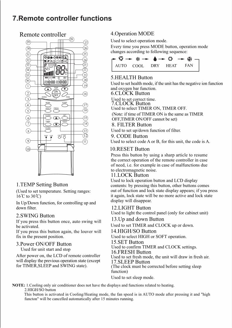
14.HIGH/SO ButtonUsed to select HIGH or SOFT operation.
21
22
31
29
32
FRESH
HIGH/SOTIMER
SET
FILTER
B A
M D
HEALTH
RESET LOCK
SLEEP
FAN
TEMP
ONOFFSWING
MODE
CLOCK
CODE LIGHT
OFF
AUTO
1
234
67
9
10
11
15
13
5
8
1617
30
34
35
33 2324
25
26
2728
20
12
14
Remote controller
1.TEMP Setting Button(Used to set temperature. Setting ranges:16 C to 30 C)In Up/Down function, for controlling up anddown filter.
2.SWING ButtonIf you press this button once, auto swing willbe activated.If you press this button again, the louver willfix in the present position.
3.Power ON/OFF Button Used for unit start and stopAfter power on, the LCD of remote controllerwill display the previous operation state (exceptfor TIMER,SLEEP and SWING state).
4.Operation MODEUsed to select operation mode.Every time you press MODE button, operation modechanges according to following sequence:
5.HEALTH ButtonUsed to set health mode, if the unit has the negative ion functionand oxygen bar function.
AUTO FANHEATCOOL DRY
6.CLOCK ButtonUsed to set correct time.
(Note: if time of TIMER ON is the same as TIMEROFF,TIMER ON/OFF cannot be set)
10.RESET ButtonPress this button by using a sharp article to resumethe correct operation of the remote controller in caseof need, i.e. for example in case of malfunctions dueto electromagnetic noise.
17.SLEEP Button(The clock must be corrected before setting sleepfunction)Used to set sleep mode.
13.Up and down ButtonUsed to set TIMER and CLOCK up or down.
8. FILTER ButtonUsed to set up/down function of filter.
NOTE: 1.Cooling only air conditioner does not have the displays and functions related to heating. 2.HIGH/SO button This button is activated in Cooling/Heating mode, the fan speed is in AUTO mode after pressing it and "high functon" will be cancelled automatically after 15 minutes running.
11.LOCK ButtonUsed to lock operation button and LCD displaycontents: by pressing this button, other buttons comesout of function and lock state display appears; if you pressit again, lock state will be no more active and lock statedisplay will disappear.
7.Remote controller functions
7.CLOCK ButtonUsed to select TIMER ON, TIMER OFF.
9. CODE ButtonUsed to select code A or B, for this unit, the code is A.
18
12.LIGHT ButtonUsed to light the control panel (only for cabinet unit)
15.SET ButtonUsed to confirm TIMER and CLOCK settings.16.FRESH ButtonUsed to set fresh mode, the unit will draw in fresh air.
1936

Clock Set
Displays when healthy run function is set.
22.TEMPERATURE Display
34.LOCK State Display
33.BATTERY Energy DisplayNotify the user when it is time to changethe batteries.
24.HIGH/SO Display25.SIGNAL SENDING Display26.FRESH AIR Display27.ELECTRICAL HEATING Display
29.HEALTH Display
32.SLEEP State Display
31.Operation MODE DisplayAUTO RUN COOL RUN DRY RUN HEAT RUN FAN RUN
35.FAN SPEED Display
23.AUTO SWING Display
19.TIMER OFF Display
21.FILTER Display
36.TIMER ON Display
When unit is started for the first time and after replacing batteries in remotecontroller, clock should be adjusted as follows:1.Press CLOCK button, clock indication of " AM " or " PM " flashes.2.Press or to set correct time. Each press will increase or decrease 1 min. If the button is kept pressed, time will increase or decrease quickly.3.After time setting is confirmed, press "SET" : AM or PM stop flashing, while clock starts working.Note:AM means morning and PM means afternoon.
When operating the remote controller in an area whereelectronically controlled lights are installed or wireless handsetsare used, please move closer to the indoor unit as the functionof the remote controller might be affected by signals emittedby the above mentioned equipments.
Battery loading
Confirmation indicatorIf no indication is displayed after press ON/OFF button,reload the batteries.
AUTO
LO
MID
HI
AUTO
Remote Controller' OperationWhen in use, direct signal transmissionhead to the receiver placed on the indoorunit
The distance between the remote controller and the receivershould be max 7m and there should be no obstacle between them.Do not throw the remote controller; prevent it from beingdamaged.
18.FAN ButtonUsed to select fan speed:LOW,MID,HIGH,AUTO.
Note:It is recommended that the batteries be removed from thecompartment if the remote controller is not used for an extendedperiod.The remote controller is programmed for automatic test ofoperation mode after the batteries are replaced. When the testis conducted, all icons will appear on the screen and thendisappear if the batteries are properly fitted.
Caution:
If the remote controller does not operate as designed afterfitting new batteries of the sametype, press the Reset button (marked ) with a pointed article.
20.CLOCK Display
30.DEHUMIDIFICATION Display
28.Some other buttonsAll these functions are not available now.
FRESH
HIGH/SOTIMER
SET
FILTER
HEALTH
RESET LOCK
SLEEPMODE
CLOCK
CODE LIGHT
321
Battery loadingBatteries are fitted as follows:
Loading the batteryEnsure that batteries are correctly placed in the compartmentas required for positive and negative terminals.
Replacing the battery compartment lidThe battery compartment lid is reinstalled in the reversesequence.
Display reviewPress the button to see if batteries are properly fitted. Ifno display appears, refit the batteries.
Remove the battery compartment lidSlightly press and disengage the battery compartment lid markedwith ì î and then hold the remote controller by the uppersection and then remove the battery compartment lid by pressingin the direction of the arrow as shown in the figure above.
* ** *

Fan Operation 1.Unit startPress ON/OFF button to start your air conditioner.Previous operation status appears on LCD (except forTIMER, SLEEP, and SWING setting).
2.Select operating modePress MODE button. At each press, operation modechanges as follows:
3. Adjust fan speedPress FAN button. At each press, fan speed changes asfollows:
Air conditioner will run at the selected fan speed.When in AUTO mode, unit will adjust fan speedaccording to room temperature automatically.
4. Unit stopPress ON/OFF button to stop unit.
Then select FAN
About FAN modeWhen the air conditioner runs in FAN mode,it is not possible to select AUTO FAN or toset temperature.
AUTO FANHEATCOOL DRY
A
FRESH
HIGH/SOTIMER
SET
FILTER
HEALTH
RESET LOCK
SLEEP
FAN
TEMP
ONOFFSWING
MODE
CLOCK
CODE LIGHT
AUTO
41 3
2LOW MID HIGH

AUTO, COOL , HEAT and DRY Operation
1. Unit startPress ON/OFF button,unit starts.Previous operation status appears on LCD (except for TIMER,SLEEP and SWING setting)
3.Temperature setting
Then select AUTO run or select COOL operation or
select DRY operation or select HEAT operation
2.Select operation modePress MODE button. At each press, operation mode changesas follows:
Press TEMP button.Every time the button is pressed, temp. setting increases1 C; if the button is kept pressed, temp. setting will increasequickly.Every time the button is pressed, temp. setting decreases1 C, if the button is kept pressed, temp. setting will decreasequickly.Set proper temperature
4.Adjust FAN buttonPress FAN button. At each press, fan speed changes as follows:
Air conditioner will run at the selected fan speed.
5. Unit stopPress ON/OFF button,unit stops.
In ATUO mode, the temperature setting is not displayed on LCD. In this mode, during running air conditionerwill select COOL, HEAT or FAN mode automatically according to the room temperature.In DRY mode, when room temperature becomes 2 C higher than temperature setting, unit will run intermittentlyat LOW speed regardless of FAN setting. When room temperature is lower than temperature setting, unit willonly run FAN operation.In HEAT mode,warm air will blow out after a short period of time due to cold-draft prevention function.
AUTO FANHEATCOOL DRY
AUTO LOW MID HIGH
FRESH
HIGH/SOTIMER
SET
FILTER
A
HEALTH
RESET LOCK
SLEEP
FAN
TEMP
ONOFFSWING
MODE
CLOCK
CODE LIGHT
AUTO
Temp. setting +2 CTemp.setting
On reaching temp.setting+2 C, unit will run in mildDRY mode.
Ultra-low air flow
COOL operation startswhen room temp.ishigher than temp.setting.
3
5 13
4
2
AUTO
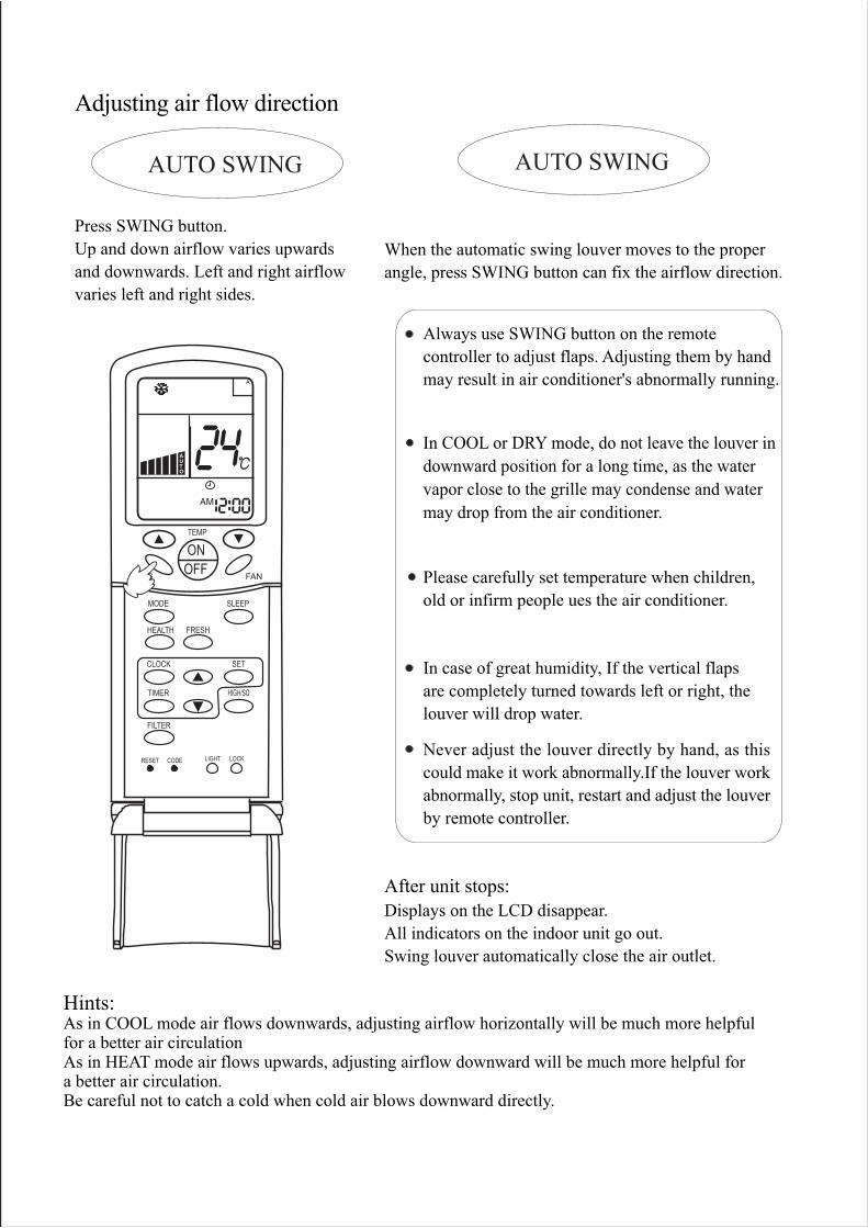
Press SWING button.Up and down airflow varies upwardsand downwards. Left and right airflowvaries left and right sides.
Always use SWING button on the remotecontroller to adjust flaps. Adjusting them by handmay result in air conditioner's abnormally running.
Displays on the LCD disappear.All indicators on the indoor unit go out.Swing louver automatically close the air outlet.
After unit stops:
AUTO SWING
Adjusting air flow direction
AUTO SWING
When the automatic swing louver moves to the properangle, press SWING button can fix the airflow direction.
Please carefully set temperature when children,old or infirm people ues the air conditioner.
In case of great humidity, If the vertical flapsare completely turned towards left or right, thelouver will drop water.
Never adjust the louver directly by hand, as thiscould make it work abnormally.If the louver workabnormally, stop unit, restart and adjust the louverby remote controller.
Hints:As in COOL mode air flows downwards, adjusting airflow horizontally will be much more helpfulfor a better air circulationAs in HEAT mode air flows upwards, adjusting airflow downward will be much more helpful fora better air circulation.Be careful not to catch a cold when cold air blows downward directly.
In COOL or DRY mode, do not leave the louver indownward position for a long time, as the watervapor close to the grille may condense and watermay drop from the air conditioner.
FRESH
HIGH/SOTIMER
SET
FILTER
A
HEALTH
RESET LOCK
SLEEP
FAN
TEMP
ONOFFSWING
MODE
CLOCK
CODE LIGHT
AUTO

Sleep FunctionBefore going to bed you can press down the SLEEP button and the air conditioner will run so as to makeyou sleep more comfortably.Before using this function, the clock must be set.
Use of SLEEP functionAfter the unit's start, set running mode and then press SLEEP button once to make the air conditionerhave the previous-set sleep time (first power-on is "1h"). The sleep symbol will appear. Press time button / : you can choose the time in 1~8 hours. Each time the button is pressed, the time increases/decreases 1hour: "xh" and "OFF" indications appear on the display.
Operation Mode
1.In COOL, DRY modeOne hour after sleeping operation start, the temperatureis 1 C higher than the setting one. After another hour,temperature rises 1 C: sleep run continuously for another6 hours and then stops. The actual temperature is higherthan the setting one which is to prevent from being toocold to your sleep.
2.In HEAT modeOne hour after sleeping operation start, the temperatureis 2 C lower than the setting one. After another hour,temperature decreases by 2 C more. Temperature willautomatically rise by 1 C after another 3 hours'continuous operation. The actual temperature is lowerthan the setting one which is to prevent from being toohot to your sleep.
3.In AUTO mode.The air conditioner will run in corresponding sleepoperation according to the automatically selectedoperation mode.
SLEEP RUN BEGINS SLEEP RUN STOPS
SETTING T SHUT DOWN
about 6 hrs
1 hrs
In COOL,DRY mode
increase 1 C
increase 1 C
SLEEP RUN BEGINS SLEEP RUN STOPS
SETTING T SHUT DOWN
1 hrs1 hrs
3 hrsabout 6 hrs
increase 1 C
decrease 2 C
decrease 2 C
Notes:After setting SLEEP function, it is not possible to set clock.If set-sleep time does not reach 8 hours, unit will automatically stop operationafter set time is reached.Set " TIMER ON " or " TIMER OFF "In COOL,DRY mode function first,then set SLEEP. After set SLEEP function, the TIMER function cannot beset.
In HEAT mode
FRESH
HIGH/SOTIMER
SET
FILTER
A
HEALTH
RESET LOCK
SLEEP
FAN
TEMP
ONOFFSWING
MODE
CLOCK
CODE LIGHT
OFF
AUTO

Every time the button is pressed, time increases 10 minuts.If the button is kept pressed, time changes quickly.
Timer ON/OFF FunctionSet clock correctly before starting TIMER operation
1.Unit startAfter unit start, select your desired operation mode (operationmode will be displayed on LCD)2.TIMER mode selectionPress TIMER button on the remote controller to change TIMERmode. Every time the button is pressed, display of TIMER modechanges as follows:
ON OFF ON OFFAM12:00 AM12:00PM 12:00 PM 12:00
TIMER ON TIMER OFF TIMER ON-OFF
blank
Then select TIMER mode as needed (TIMER ON or TIMER OFF).Now or will flash.
3.TIMER setting (press time adjust buttons )
Every time the button is pressed, time decreases 10 minuts.If the button is kept pressed, time changes quickly.It can be adjusted within 24 hours at will.
4.Confirm settingAfter setting correct time, press SET button to confirm time. Now
Time displayed: unit starts or stops at X hour X min (TIMER ONor TIMER OFF)5.Cancel TIMER modeJust press TIMER button several times until TIMER mode disappears.
Hints:After replacing batteries or if a power failure occurs, TIMER settingmust be reset.Remote controller has memory function. When you use TIMERmode next time, just press SET button after mode selection if timersetting is the same as the previous one.
Note:After setting TIMER function, the remote controller displays TIMER time. If you want to see clock time,just press CLOCK button once: clock time will be displayed (if you press the button again continuously,youcan adjust clock). 5 seconds later, the display will show TIMER time again.
ON OFF
ON OFFor stop flashing.
FRESH
HIGH/SOTIMER
SET
FILTER
A
HEALTH
RESET LOCK
SLEEP
FAN
TEMP
ONOFFSWING
MODE
CLOCK
CODE LIGHT
1
2
3 4

Timer ON-OFF FunctionSet clock correctly before starting TIMER operation
1.Unit startAfter unit start, select your desired operation mode (operationmode will be displayed on LCD)
2.TIMER mode selectionPress TIMER button on the remote controller to change TIMERmode. Every time the button is pressed, display of TIMER modechanges as follows:
OFF
3.Time setting for TIMER ON
4.Timer confirming for TIMER ONAfter setting correct time, press TIMER button to confirm time. Now
5.Timer setting for TIMER OFFPress time buttons and follow the same procedures in " Time settingfor TIMER ON"
Press time button
ON stops to flash, while starts flashing.
Time displayed : unit starts at X hour X min.
6.Time confirming for TIMER OFFAfter time setting, press SET button to confirm time. stops to flash.Time displayed: unit starts at X hour X min.
7.Canel TIMER modeJust press TIMER button several times until TIMER mode disappears.According to the time setting sequence of TIMER ON and TIMER OFF,either start-stops or stops-start can be realized.
If the time setting of TIMER ON is the same as TIMER OFF, TIMERON-OFF function cannot be set.
ONThen select TIMER ON-OFF mode. will flash.
Every time the button is pressed, time increases 10 minuts.If the button is kept pressed, time will changes quickly.
Every time the button is pressed, time decreases 10 minuts.If the button is kept pressed ,time will changes quickly.It can be adjusted within 24 hours at will.AM refers to morning and PM refers to afternoon.
OFF
FRESH
HIGH/SOTIMER
SET
FILTER
A
HEALTH
RESET LOCK
SLEEP
FAN
TEMP
ONOFFSWING
MODE
CLOCK
CODE LIGHT
OFF
1
3 654
2
ON OFF ON OFFAM12:00 AM12:00PM 12:00 PM 12:00
TIMER ON TIMER OFF TIMER ON-OFF
blank

After the air conditioner has operated for a certain period, dust hasaccumulated on the filter, and the filter up/down function can be usedto clean it.
1.Whether unit starts or stops, continuously press FILTER button for 3 seconds, and enter the filter up/down waiting status (when unit stops, the yellow TIMER indicator flashes, and filter and clock indication are displayed on the remote controller. Only the FILTER button, the temperature buttons " " " " and time buttons are active).
2.Press temperature button or time button in filter up/down waiting status: the up/down mechanism makes the filter moving downward and does not stop until it has reached the maximum limit.
3.Press temperature button or time button in filter up/down waiting status: the up/down mechanism makes the filter to moving upward till near the surface board and then automatically adjusts it to reset (when adjusting to reset, it will not be controlled by the remote controller till the adju- stment is finished).
4.During moving downward, press temperature button or time button: moving stops.
5.During moving downward, press temperature button or time button: moving stops.
6.Continuously press FILTER button 3 seconds again to cancel the filter up/down waiting mode (unit stops, the yellow timer indicator stops flashing, the filter goes back to the original position, the remote controller goes back to off status and only clock is displayed).
Note:If the filter does not thoroughly go back to the original position, only needs tooperate several times repeatedly.
Filter Up/Down
" "
" "
" "
" "
" "
" "" "
" "
(Only for 600*600panel)
FRESH
HIGH/SOTIMER
SET
FILTER
A
HEALTH
RESET LOCK
SLEEP
FAN
TEMP
ONOFFSWING
MODE
CLOCK
CODE LIGHT1

Press the HIGH/SO button twice
NOTICE:When the air conditioner is operating in " High Mode " , unevenness of room air temperaturemay occur due to the intensive operation in a short time.Anyway, operation in "High Mode", does not last for more than 15 minutes, then regularoperation is automatically restored.
" High mode " Operation
If the button is pressed once, the indication is displayedon the remote controller. If you press the button once again,the indication disappears, regular operation is restored and fanspeed goes back to the mode set before "High Mode" operation.
Press the HIGH/SO button noceThe indication appears on the display of the remotecontroller and operation in "High Mode" starts.The AUTO fan speed is automatically set and the correspondingindication is also displayed.
Outline of operation in "High Mode"This function is suitable when the set temperature must bereached in the shortest delay.The button "HIGH/SO", referred to this function, is effectivein Cooling/Heating mode (not in Auto/Dry/Fan modes).
ON
OFF
FRESH
HIGH/SOTIMER
SET
FILTER
A
HEALTH
RESET LOCK
SLEEP
FAN
TEMP
ONOFFSWING
MODE
CLOCK
CODE LIGHT
AUTO
1
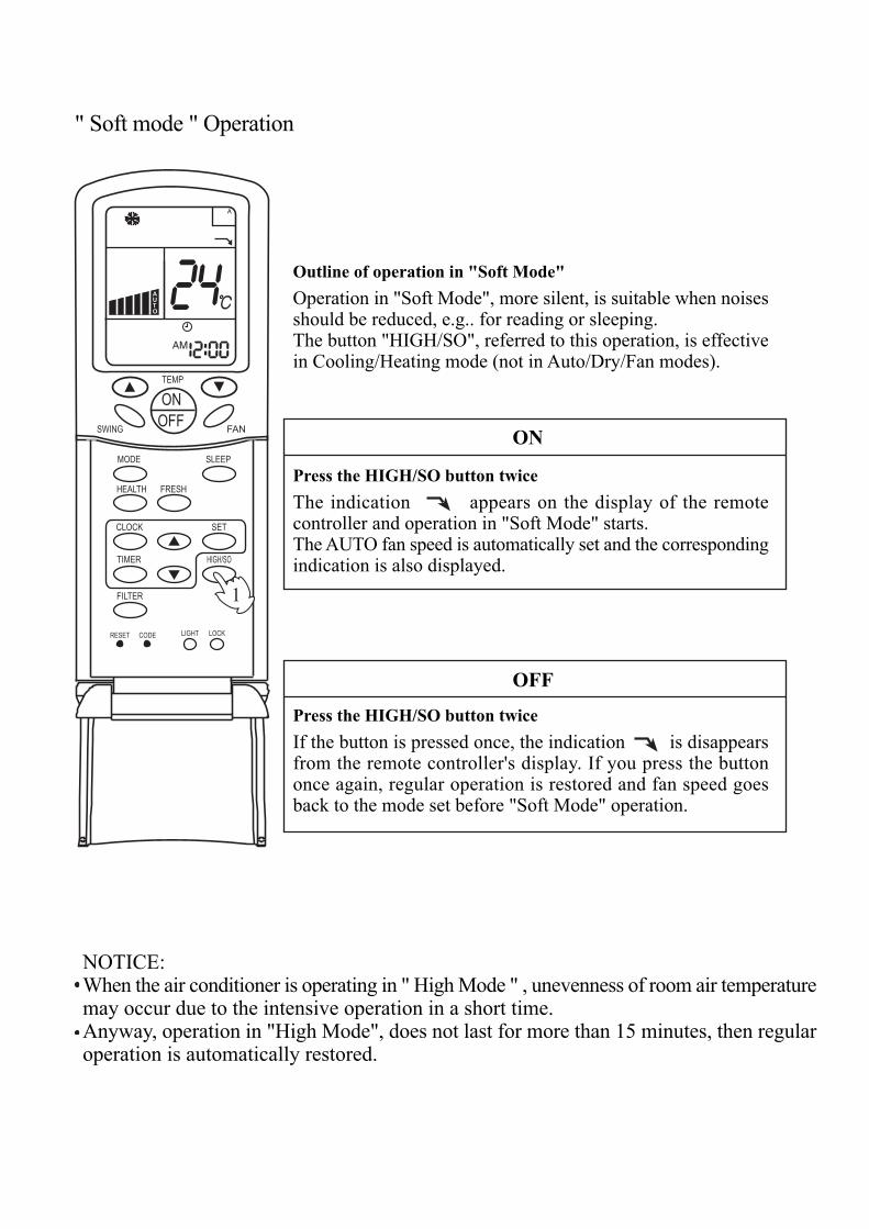
Press the HIGH/SO button twice
NOTICE:When the air conditioner is operating in " High Mode " , unevenness of room air temperaturemay occur due to the intensive operation in a short time.Anyway, operation in "High Mode", does not last for more than 15 minutes, then regularoperation is automatically restored.
" Soft mode " Operation
If the button is pressed once, the indication is disappearsfrom the remote controller's display. If you press the buttononce again, regular operation is restored and fan speed goesback to the mode set before "Soft Mode" operation.
Press the HIGH/SO button twiceThe indication appears on the display of the remotecontroller and operation in "Soft Mode" starts.The AUTO fan speed is automatically set and the correspondingindication is also displayed.
Outline of operation in "Soft Mode"Operation in "Soft Mode", more silent, is suitable when noisesshould be reduced, e.g.. for reading or sleeping.The button "HIGH/SO", referred to this operation, is effectivein Cooling/Heating mode (not in Auto/Dry/Fan modes).
ON
OFF
FRESH
HIGH/SOTIMER
SET
FILTER
A
HEALTH
RESET LOCK
SLEEP
FAN
TEMP
ONOFFSWING
MODE
CLOCK
CODE LIGHT
OFF
AUTO
1
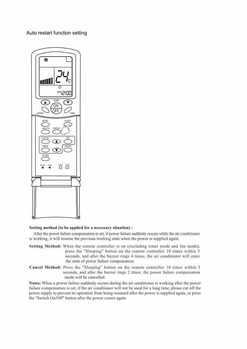
Auto restart function setting
Setting method (to be applied for a necessary situation) :
Setting Method: When the remote controller is on (excluding timer mode and fan mode), press the "Sleeping" button on the remote controller 10 times within 5 seconds, and after the buzzer rings 4 times, the air conditioner will enter the state of power failure compensation.Cancel Method: Press the "Sleeping" button on the remote controller 10 times within 5
seconds, and after the buzzer rings 2 timer, the power failure compensation mode will be cancelled.Notes: When a power failure suddenly occurs during the air conditioner is working after the powerfailure compensation is set, if the air conditioner will not be used for a long time, please cut off thepower supply to prevent its operation from being resumed after the power is supplied again, or pressthe "Switch On/Off" button after the power comes again.
After the power failure compensation is set, if power failure suddenly occurs while the air conditioneris working, it will resume the previous working state when the power is supplied again.
FRESH
HIGH/SOTIMER
SET
FILTER
A
HEALTH
RESET LOCK
SLEEP
FAN
TEMP
ONOFFSWING
MODE
CLOCK
CODE LIGHT
AUTO

C
HEALTH
SET RECOVERY
CHECK
F
Cautions:On cooling only unit, heatingmode is not available.
Note:The above information is the explanation ofthe displayed information therefore varieswith those displayed in actual operation.
CLOCKUsed to adjust time.
TIMERUsed to set timermode.
stands for time plus/minus,used to adjust time.
Used for unit start andstop.
POWER ON/OFF
MODE
Used for selectindoor operationmode.
FAN SPEEDUsed for select indoorair flow.
HEALTHUsed for settingindoor healthfunction.
TEMP + -
Used for changingset temperature.
RECOVERYused to switchover air-exchanging mode.
SWINGUsed for sett ingindoor swing mode.
Auto-diagnost icbutton.
Filter-cleaned button.
FILTER
RESETReset correctmode button.
Wired controller YR-E12 functions:
CHECK
+ -
Buttons and functions of the wired controller

Buttons functionMODE used for select indoor operation mode. FAN used for select indoor air flow. SWING used for setting indoor swing mode. HEALTH used for setting indoor health function. TEMP + - used for changing set temperature. CLOCK used to adjust time. + - stands for time plus/minus, used to adjust time. TIMER used to set timer mode. RECOVERY used to switch over air-exchanging mode. CHECK auto-diagnostic button. FILTER filter-cleaned button.
RESET reset correct mode button.
Display description[MODE] [AUTO] auto operation mode [MODE] [FAN ONLY] air-throwing mode [MODE] [COOL] Cooling operation mode [MODE] [DRY] Dehumidification mode [MODE] [HEAT] Heating operation mode [MODE] [HEAT] [TES] In heating mode, auxiliary electric heater is running. Only when the
unit with auxiliary electric heater is in auxiliary electric heating mode, it will display. [FAN] [AUTO] auto fan running

[FAN] [HIGH] high fan speed [FAN] [MED] medium fan speed [FAN] [LOW] low fan speed [FAN] [FIX] fixed fan speed, it will display only when fixed fan speed is requested to main
indoor unit. [CENTRAL] central control mode [OPERATION] running mode [STAND BY] waiting mode [PRE-HEAT] pre-heating mode [DEFROST] defrosting mode [FILTER] request of filter to be cleaned [HEALTH] health function [UNIT NO.] [CEN.ADD] central control address, the address number will display on “88[SYS.ADD.] system address, the address number will display on “88[CHECK] auto-diagnostic, trouble shooting [DEMAND] compulsory operation function, when it works, [CENTRAL] will flash [SWING] swing mode [ROOM TEMP.] indoor ambient temperature [SET TEMP.] set admired temperature [TIMER][ON] timer function is on, it will switch over in the sequence below:
[ON][OFF] [ON][OFF][DAILY] [ ] [TIMER][OFF] timer function is off [TIMER][ON][OFF] timer function ON-OFF [TIMER][ON][OFF][DAILY] timer ON-OFF will switch over in turn daily [CLOCK] clock display, the displaying time is the current time of the clock. [UP] [DOWN] indicator of filter elevating [VENTILATION][AUTO] auto ventilation mode [VENTILATION][RECOVERY] fully heat exchanging ventilation mode [VENTILATION][NORMAL] normal ventilation mode
FAN ONLY OPERATION1 Start up operation: press the button of ON/OFF, the system will start up, and will display [MODE][AUTO] [FAN][AUTO] [ROOM TEMP.]+ 24 [CLOCK]+”12 00”.2 Select MODE: press the MODE button, then you will see in the display section [MODE]
switch over in below sequence:[FAN ONLY] [COOL] [DRY] [HEAT] [AUTO][FAN ONLY]. Select [FAN ONLY].
3 Select fan speed: press FAN button, then you see in the display section [FAN] switch over in below sequence: [HIGH] [MED] [LOW] [HIGH]. Select proper fan speed. 4 Power off: press ON/OFF button, indoor unit will be powered off, there are only time and the ambient temperature in the screen.

AUTO operation, COOLING, HEATING and DEHUMIDIFICATION operation
1) Start up operation: press the button of ON/OFF, the system will start up, and will display [MODE][AUTO] [FAN][AUTO] [ROOM TEMP.]+ 24 [CLOCK]+”12 00”.2) Select MODE: press the MODE button, then you will see in the display section [MODE] switch over in below sequence:[FAN ONLY] [COOL] [DRY] [HEAT] [AUTO] [FAN ONLY]. Select [FAN ONLY]. 3) Change set temperature: press TEMP + or – every time, [SET] will display, and set temperature will increase/reduce 1 F .4) Select fan speed: press FAN button, then you see in the display section [FAN] switch over in below sequence: [HIGH] [MED] [LOW] [HIGH]. Select proper fan speed. 5) Select [SWING]: press [SWING] button, swing function is valid. Press again, swing
function is invalid. 6) Set [HEALTH]: used to set the indoor health function. Press it once, [HEALTH] will display in the display section, then indoor health function is valid. Press it again, [HEALTH] will disappear, then the health function is invalid. This function is valid only for the unit with health function. 7) Power off: press ON/OFF button, indoor unit is powered off. There are only time and the ambient temperature in the screen.
Set TIMER operation:
Adjust clock: when powered on, for the first time to set timer function, the clock will be adjusted.Press “CLOCK” button, and set the current clock. Now, “CLOCK” will flash at the frequency of 2Hz every minute. Press the clock +/- button; the current clock can be adjusted. Until the proper time comes, press [SET].
TIMER ON operation: Press TIMER button, and keep pressing it, in the display section [TIMER] will switch over in below sequence: [ON] [OFF] [ON][OFF] [ON][OFF][DAILY] [ ]. Select [TIMER] [ON], then [TIMER] [ON] flashes, press the clock +/- button to adjust the time of TIMER ON, press [SET] button.
TIMER OFF operation: Press TIMER button, and keep pressing it, in the display section [TIMER] will switch over in below sequence: [ON] [OFF] [ON][OFF] [ON][OFF][DAILY] [ ]. Select [TIMER] [OFF], then [TIMER] [OFF] flashes, press the clock +/- button to adjust the time of TIMER OFF, press [SET] button.
TIMER ON-OFF operation: Press TIMER button, and keep pressing it, in the display section [TIMER] will switch over in below sequence: [ON] [OFF] [ON][OFF] [ON][OFF][DAILY] [ ]. Select [TIMER] [ON] [OFF]. Firstly, [TIMER][ON] flashes, press the clock +/- button to adjust the time of

TIMER ON, press [TIMER]. [TIMER][ON] will be constant on. Then [TIMER] [OFF] flashes, press the clock +/- button to adjust the time of TIMER OFF, press [SET]. The time sequence of timer on and timer off will determine the mode is [TIMER] [ON] [OFF] or [TIMER] [OFF]
[ON]. If you want the current time, press [CLOCK] once, current time will display; press again, [CLOCK] will flash, and press [+][-] to adjust the time. Note: 1. If the two times are same, the timer state which is set later will flash, in this case, timer can not be set. 2. When entering TIMER setting state, if you do not input any button in continuous 10 seconds, the unit will quit from the TIMER mode.
Cancel TIMER operation: In the timer operation state, press [TIMER] button, the unit will quit from the current timer operation state, and the set data will be memorized, then enter the next timer mode.
[FILTER] function When the wired controller receives the filter-cleaned signal from indoor unit, [FILTER] will display. After finishing clean, press [FILTER], the sign [FILTER] disappears, and the controller will send the filter reset signal to indoor unit. When the sign [FILTER] not display, it is invalid to press [FILTER] in short time.
FILTER ELEVATING function: (only for the unit with elevating function) When the filter needs to be cleaned, the panel can be lowered to the admired height by the [FILTER][UP][DOWN] function. Method is below: In power off state, press [HEALTH] for 15 seconds to enter filter elevating set state. In this state, the sign [FILTER] will flash and [UP] [DOWN] will display simultaneously, Press TEMP [+], in timer section [UP] will display, while press TEMP [-], in timer section [DOWN] will display. When it arrives the appropriate position, press [UP], [UP][DOWN] will display simultaneously, filter will stop going down. Press [UP] again, filter will go up. Press [FILTER] button to quit the mode.
DEMAND operation function: By this function, all the indoor units can be made in nominal mode. Set the operation mode in cooling and then shut off the unit. In the stop state, press [ON/OFF] button for 5 seconds to enter cooling trial operation state. If it is in heating mode before shut off the unit, then press [ON/OFF] button for 5 minutes, it will enter heating trial operation state.
In cooling, there will be “LL” in the position where the set temperature displays. In heating, there will be “HH” in the position where the set temperature displays. The wired controller will send the [DEMAND] signal to indoor unit. In the [DEMAND] operation, “COOL” or “HEAT” will display at 1Hz frequency. Indoor fan motor will be fixed at “AUTO” mode. The indoor units in the same group will quit the [DEMAND] in turn.
At this time, only the buttons of [ON/OFF] and temperature [+] [-] are valid. Press [ON/OFF] to quit [DEMAND] mode.

CENTRAL control function When the central controller selects [CENTRAL] mode, the buttons in the wired controller except for [CHECK] will be invalid. VENTILATION mode (only for the unit with fresh air function or heat recovery function)Press [RECOVERY] button, then the unit will switch over the ventilation mode: [ ] [VENTILATION][AUTO] [VENTILATION][RECOVERY] [VENTALATION][NORMAL] [ ], please select appropriate ventilation mode.
Query indoor malfunction history: In the state of power on or power off, press [CHECK] button, enter the malfunction-querying mode of all indoor units in the group. Then [CHECK] and [UNIT NO.] will display, and the actual indoor numbers will be displayed in some sequence (unit number is in decimals). At the same time, in the time region, there will be the current malfunction and the latest time malfunction, the displaying format is [XX YY], in which XX stands for the current malfunction, if normal, it will display “ ”; YY stands for the latest time malfunction. The failure code of every unit will display for 3 seconds. After the failure codes of all indoor units in the whole group are displayed, the mode will quit automatically.
Clear abnormal state and malfunction history: In normal state, press [CHECK] button for 5 seconds to clear abnormal states, at the same time, wired controller will send the data of “clear abnormal state”, but the malfunction history still retains. In normal state, press [CHECK] button for 15 seconds, except for malfunction states, the malfunction history in wired controller will be cleared.
Query indoor performance state: In normal state, press both buttons of [CHECK] and [FILTER] for 5 seconds, in the set temperature region in the screen, [XX] will display, XX is indoor number, which can be selected by pressing [TEMP] [+] [-]. In the timer region in the screen, [YZZZ] will display, in which Y stands for data type, ZZZ stands for the corresponding data. which can be selected by pressing [CLOCK] [+] [-].
Y ZZZ Type A Indoor capacity (W) Nominal cooling
capacity/10, decimal B Request of indoor capacity Hz Actual value, decimal C Temperature of indoor ambient
temp. sensor TA Actual value, decimal
d Temperature of indoor gas pipe sensor TC1
Actual value, decimal
E Temperature of indoor liquid pipe sensor TC2
Actual value, decimal
F Open degree of indoor PMV Actual value, decimal

g Preset H Outdoor total capacity Actual value, decimal
In check mode, press [CHECK] to quit the check mode, and go into normal running mode.
How to change the function switches? No. Type State of
switchFunction description
Connected Central controller J01 Changeover of Wired controller and central controller
Cut off Wired controller
Connected Set as simple controller J02 Changeover of type of wired controller Cut off Set as standard controller
Connected Use the sensor in the wired controller
J06 Selection of room temp. sensor
Cut off Use the sensor in the indoor unit Connected Common control J07 Auto restart after power
failure Cut off Auto restart after power failure Connected Yes J03 Display of room
temperature Cut off No ON Set as slave controller SW01 Changeover of master or
slave controller OFF Set as master controller ONSW01 or OFFConnected Indoor unit in shorted time
functionD1 Shorten time function
Cut off Common control Connected Send compulsorily defrost signal
to indoor unit D2 Compulsorily defrost
Cut off Common control Note: 1. The switches in grey can be operated after opening the cover of wired controller. 2. Switches or jumper wire must be adjusted when the wired controller is powered off. If the wired controller is powered on, the above operations will be invalid. 3. Shorten time function In normal operation, D1 is in short circuit, it will enter shorten time mode, and the time will be shortened in the proportion of 60:1. In shorten time mode, LED will flash at the frequency of 0.5 second. Cut off D1, it will quit the shorten time mode and return to the normal operation mode.4. Compulsorily defrost In heating mode, D2 is in short circuit, it will enter compulsorily defrost mode; cut off D2, it will quit. 5. Lock function There is no lock function only in the wired controller. But when it is connected with a central

controller, if the central controller is set to “central”, the buttons in the wired controller will be invalid, or the buttons will be valid.
Failure code: For
remotetype,flashtimes
Failurecode on
wiredcontroller
Forcentralcontrol,failurecode
Failure description Reason Remarks
10 08(08H) 21D Drainage system abnormal
Float switch broken down for more than 25m continuously
1 01(01H) 01D Indoor ambient temp. sensor failure
sensor broken down or short circuit for more than 2m continuously
2 02(02H) 02D Indoor coil temp. sensor failure
sensor broken down or short circuit for more than 2m continuously
3 74(4AH) 11D Outdoor ambient temp. sensor failure
sensor broken down or short circuit for more than 2m continuously
4 73(49H) 12D Outdoor coil temp. sensor failure (compressordischarging temp. sensor)
Sensor broken down or short circuit for more than 2m continuously
5 72(48H) 10D Over-current protection
CT check abnormal 3 times in 30m
6 83(53H) 14D High pressure abnormal
High pressure switch acts 3 times in 30m
7 71(47H) 22D Power supply abnormal
Fault phase, short of phase, out of balance greatly
8 07(07H) 06D Communication between wired controller and indoor abnormal
Communication abnormal for more than 4m continuously
9 06(06H) 05D Communication between indoor and outdoor abnormal
Communication abnormal for more than 4m continuously
11 11(0BH) 30D Outside alarm signal input
Outside signal broken down for more than 10s
12 03(03H) 20D Gas pipe temp. sensor abnormal
Sensor broken down or short circuit for more than

2m continuously 13 13(0DH) 31D Solenoid valve
abnormalSolenoid valve act incorrectly 3 times continuously
14 76(4CH) 15D Discharging temp. sensor abnormal
Sensor broken down or short circuit for more than 2m continuously
15 05(05H) 17D EEPROM abnormal EEPROM data missing Run as the defaultvalue
16 84(54H) 26D Pressure abnormal(low pressure)
Low pressure switch acts in normal running
17 80 50H 15D Compressor overheat the discharging temperature is higher than 120degree
Resumableif lower than100degree
18 12 0CH 23D Abnormal mode Indoor operation mode is different with the running indoor unit.
19 75 4BH 18D Outdoor coil B(suction temp sensor—for MRV II)
Sensor broken down or short circuit for more than 2m continuously
20 77 4DH 15D Outdoor discharging B(oil temp sensor—for MRV II)
Sensor broken down or short circuit for more than 2m continuously
shows resumable fault, shows it is not resumable fault.
Setting address method: The address setting can be realized by setting indoor PCB. If you use the group control function, there should be a master unit and 15 sets of slave units. For the master unit, the SW5-3 should be at “1”. For the slave units, the SW5-3 should be at “0”.Please refer the below table, Indoor
unitaddress
SW1-4 SW1-3 SW1-2 SW1-1
1 OFF OFF OFF OFF 2 OFF OFF OFF ON 3 OFF OFF ON OFF 4 OFF OFF ON ON 5 OFF ON OFF OFF 6 OFF ON OFF ON 7 OFF ON ON OFF

8 OFF ON ON ON 9 ON OFF OFF OFF 10 ON OFF OFF ON 11 ON OFF ON OFF 12 ON OFF ON ON 13 ON ON OFF OFF 14 ON ON OFF ON 15 ON ON ON OFF 16 ON ON ON ON
If you use central control type, SW1, SW2 will be used simultaneously. Wiring request in central control type: port A-B is connected with indoor port CN16 A-Bthrough 2-core shield wire. Requirements: 1. Port A connects with port CN16 A of all indoor units. 2. Port B connects with port CN16 B of all indoor units. Address on centralcontroller
Indoor unit address
SW2-3 SW2-2 SW2-1 SW1-4 SW1-3 SW1-2 SW1-1
1 1 ON OFF OFF OFF OFF OFF OFF 2 2 ON OFF OFF OFF OFF OFF ON 3 3 ON OFF OFF OFF OFF ON OFF 4 4 ON OFF OFF OFF OFF ON ON 5 5 ON OFF OFF OFF ON OFF OFF 6 6 ON OFF OFF OFF ON OFF ON 7 7 ON OFF OFF OFF ON ON OFF 8 8 ON OFF OFF OFF ON ON ON 9 9 ON OFF OFF ON OFF OFF OFF 10 10 ON OFF OFF ON OFF OFF ON 11 11 ON OFF OFF ON OFF ON OFF 12 12 ON OFF OFF ON OFF ON ON 13 13 ON OFF OFF ON ON OFF OFF 14 14 ON OFF OFF ON ON OFF ON 15 15 ON OFF OFF ON ON ON OFF 16 16 ON OFF OFF ON ON ON ON 17 -------- ON OFF ON OFF OFF OFF OFF 18 -------- ON OFF ON OFF OFF OFF ON 19 -------- ON OFF ON OFF OFF ON OFF 20 -------- ON OFF ON OFF OFF ON ON 21 -------- ON OFF ON OFF ON OFF OFF 22 -------- ON OFF ON OFF ON OFF ON 23 -------- ON OFF ON OFF ON ON OFF 24 -------- ON OFF ON OFF ON ON ON 25 -------- ON OFF ON ON OFF OFF OFF

26 -------- ON OFF ON ON OFF OFF ON 27 -------- ON OFF ON ON OFF ON OFF 28 -------- ON OFF ON ON OFF ON ON 29 -------- ON OFF ON ON ON OFF OFF 30 -------- ON OFF ON ON ON OFF ON 31 -------- ON OFF ON ON ON ON OFF 32 -------- ON OFF ON ON ON ON ON 33 -------- ON ON OFF OFF OFF OFF OFF 34 -------- ON ON OFF OFF OFF OFF ON 35 -------- ON ON OFF OFF OFF ON OFF 36 -------- ON ON OFF OFF OFF ON ON 37 -------- ON ON OFF OFF ON OFF OFF 38 -------- ON ON OFF OFF ON OFF ON 39 -------- ON ON OFF OFF ON ON OFF 40 -------- ON ON OFF OFF ON ON ON 41 -------- ON ON OFF ON OFF OFF OFF 42 -------- ON ON OFF ON OFF OFF ON 43 -------- ON ON OFF ON OFF ON OFF 44 -------- ON ON OFF ON OFF ON ON 45 -------- ON ON OFF ON ON OFF OFF 46 -------- ON ON OFF ON ON OFF ON 47 -------- ON ON OFF ON ON ON OFF 48 -------- ON ON OFF ON ON ON ON 49 -------- ON ON ON OFF OFF OFF OFF 50 -------- ON ON ON OFF OFF OFF ON 51 -------- ON ON ON OFF OFF ON OFF 52 -------- ON ON ON OFF OFF ON ON 53 -------- ON ON ON OFF ON OFF OFF 54 -------- ON ON ON OFF ON OFF ON 55 -------- ON ON ON OFF ON ON OFF 56 -------- ON ON ON OFF ON ON ON 57 -------- ON ON ON ON OFF OFF OFF 58 -------- ON ON ON ON OFF OFF ON 59 -------- ON ON ON ON OFF ON OFF 60 -------- ON ON ON ON OFF ON ON 61 -------- ON ON ON ON ON OFF OFF 62 -------- ON ON ON ON ON OFF ON 63 -------- ON ON ON ON ON ON OFF 64 -------- ON ON ON ON ON ON ON 65 -------- ON OFF OFF OFF OFF OFF OFF 66 -------- ON OFF OFF OFF OFF OFF ON 67 -------- ON OFF OFF OFF OFF ON OFF -------- ON OFF OFF OFF OFF ON ON

-------- ON OFF OFF OFF ON OFF OFF -------- ON OFF OFF OFF ON OFF ON -------- ON OFF OFF OFF ON ON OFF -------- ON OFF OFF OFF ON ON ON -------- ON OFF OFF ON OFF OFF OFF -------- ON OFF OFF ON OFF OFF ON -------- ON OFF OFF ON OFF ON OFF -------- ON OFF OFF ON OFF ON ON -------- ON OFF OFF ON ON OFF OFF -------- ON OFF OFF ON ON OFF ON -------- ON OFF OFF ON ON ON OFF -------- ON OFF OFF ON ON ON ON -------- ON OFF ON OFF OFF OFF OFF -------- ON OFF ON OFF OFF OFF ON -------- ON OFF ON OFF OFF ON OFF -------- ON OFF ON OFF OFF ON ON -------- ON OFF ON OFF ON OFF OFF -------- ON OFF ON OFF ON OFF ON -------- ON OFF ON OFF ON ON OFF -------- ON OFF ON OFF ON ON ON -------- ON OFF ON ON OFF OFF OFF -------- ON OFF ON ON OFF OFF ON -------- ON OFF ON ON OFF ON OFF -------- ON OFF ON ON OFF ON ON -------- ON OFF ON ON ON OFF OFF -------- ON OFF ON ON ON OFF ON -------- ON OFF ON ON ON ON OFF -------- ON OFF ON ON ON ON ON -------- ON ON OFF OFF OFF OFF OFF -------- ON ON OFF OFF OFF OFF ON -------- ON ON OFF OFF OFF ON OFF -------- ON ON OFF OFF OFF ON ON -------- ON ON OFF OFF ON OFF OFF -------- ON ON OFF OFF ON OFF ON -------- ON ON OFF OFF ON ON OFF -------- ON ON OFF OFF ON ON ON -------- ON ON OFF ON OFF OFF OFF -------- ON ON OFF ON OFF OFF ON -------- ON ON OFF ON OFF ON OFF -------- ON ON OFF ON OFF ON ON -------- ON ON OFF ON ON OFF OFF -------- ON ON OFF ON ON OFF ON -------- ON ON OFF ON ON ON OFF

-------- ON ON OFF ON ON ON ON -------- ON ON ON OFF OFF OFF OFF -------- ON ON ON OFF OFF OFF ON -------- ON ON ON OFF OFF ON OFF -------- ON ON ON OFF OFF ON ON -------- ON ON ON OFF ON OFF OFF -------- ON ON ON OFF ON OFF ON -------- ON ON ON OFF ON ON OFF -------- ON ON ON OFF ON ON ON -------- ON ON ON ON OFF OFF OFF -------- ON ON ON ON OFF OFF ON -------- ON ON ON ON OFF ON OFF -------- ON ON ON ON OFF ON ON -------- ON ON ON ON ON OFF OFF -------- ON ON ON ON ON OFF ON -------- ON ON ON ON ON ON OFF 128 -------- ON ON ON ON ON ON ON

Electrical functions of wired controller:
1.Function difference between master wired controller and slave one: Contrastive items Master wired controller Slave wired controller Function All of functions Only with below functions: ON/OFF,
MODE, FAN SPEED, SET TEMP., SWING
2. Wiring connections of wired controller:
indoor Nwired controller
indoor 1 indoor 2
indoor 1
indoor 16
control wiring of wired controller, polar.
indoor 15wired controller wired controller wired controller
wired controller wired controller
wired controller
wired controller
indoor 1
wired controller wired controller wired controller
A
B C
(master unit)
polar wirepolar wire
polar wire
There are three methods to connection wired controller and the indoor units: A. One wired controller can control max. up to 16 sets of indoor units, and 3 pieces
of polar wire must connect the wired controller and the master unit (the indoor unit connected with wired controller directly), the others connect with the master unit through 2 pieces of polar wire. B. One wired controller controls one indoor unit, and the indoor unit connects with the wired controller through 3 pieces of polar wire. C. Two wired controllers control one indoor unit. The wired controller connected with indoor unit is called master one, the other is called slave one. Master wired controller and indoor unit; master and slave wired controllers are all connected through 3 pieces of polar wire. 3. Communication wiring: The wired controller is equipped with special communication wiring in the accessories. 3-core terminal (1-white 2-yellow 3-red) is connected with the

terminal A B C of wired controller respectively. The communication wiring is 4 meter long; if the actual length is more than it, please distribute wiring according to below table:
Communication wiring length m Dimensions of wiring <100 0.3mm2X3-core shielded wire
100 and <200 0.5mm2X3-core shielded wire 200 and <300 0.75mm2X3-core shielded wire300 and <400 1.25mm2X3-core shielded wire400 and <600 2mm2X3-core shielded wire
One side of the shielded sheet of communication wire must be earthed.

Refrigerant Diagram
h eat
ing
o per
atio
nco
o lin
gop
erat
ion
heat
e xch
ange
r
outd
ooru
nit
ind o
orun
it
oil
sepa
rato
r
stop
valv
e
Com
pres
s or
air- l
iqui
dse
para
tor
f our
-way
valv
e
liqui
dre
ceiv
er
capi
llary
capi
llar y
sole
noid
v alv
eso
leno
idva
l ve
sole
noid
val v
e
sole
n oid
valv
e
s top
valv
e
stop
v alv
e
stop
v alv
e
stop
valv
e
stop
valv
e
sto p
valv
e
stop
valv
e
heat
e xch
ange
r
heat
exch
ange
r
heat
exch
ange
r
heat
exch
ange
r
four
-way
v alv
e
air-l
iqui
dse
para
tor
sole
noid
valv
e
sole
noid
valv
e
liqui
dre
ceiv
er
A
Co m
pres
sor
B
oil
sepa
rato
r
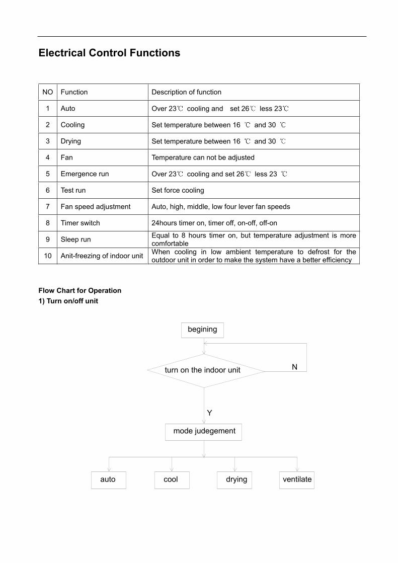
Electrical Control Functions
NO Function Description of function
1 Auto Over 23 cooling and set 26 less 23
2 Cooling Set temperature between 16 and 30
3 Drying Set temperature between 16 and 30
4 Fan Temperature can not be adjusted
5 Emergence run Over 23 cooling and set 26 less 23
6 Test run Set force cooling
7 Fan speed adjustment Auto, high, middle, low four lever fan speeds
8 Timer switch 24hours timer on, timer off, on-off, off-on
9 Sleep run Equal to 8 hours timer on, but temperature adjustment is morecomfortable
10 Anit-freezing of indoor unit When cooling in low ambient temperature to defrost for theoutdoor unit in order to make the system have a better efficiency
Flow Chart for Operation1) Turn on/off unit
turn on the indoor unit
mode judegement
Y
begining
N
auto cool drying ventilate

Haier
2) Cooling operation
loide vavle is notenergized
compressor andoutdoor fan stop
LED of operation goes on
loide valve energized
frost preventN
Y
N
compressor and outdoorfans run
LED of power goes on
does the room temp.exceedthe temp. setting
Y
LO
MID
LO
MID
manualauto
HI HI
cooling operation
indoor fan runs

Haier
3) Dehumidifying operation
Dehumidifying
Solenoid valves open,indoor unit fan motor weakwind
Solenoid valves open,indoor unit fan motor weakwind
Electronic expansionvalve totally open
A
Send indoor unit OperationState to outdoor unit
Determine if dehumidifyaccording to airtemperature
No
Yes
No
Yes
Anti-defrosting n
No
Yes
Yes
No
Adjust fan speedaccording to temperatureset and in air
If enter coolingoperation
Swing action
Swing flap in the coolingstandard position
Swing

10. Diagnostic information (trouble shooting) 10.1 Failure code Resumable failures are marked with “ ”, the others are not resumable failures. Resumable failure will disappear when the failure is eliminated and its failure code will disappear automatically within 30 seconds. But the other failure code will disappear only after the unit starts up once again. When failure occurs, the unit only can receive “OFF” signal from the controller. And when the unit is shut off, the failure code will disappear. The chart (for cassette type and duct type) please refer to the information on Page 72For wall mounted type and the console type unit, their failure code is below:
Failure description Code on wired controller(YR-E06)
Flash times of indoor receiver board
Room temp. sensor abnormal F1 Power LED flashes 1 time
Indoor coil temp. sensor abnormal (liquid pipe) F2 Power LED flashes 2 times
Refrigerant system abnormal F3 Power LED flashes 3 times
Indoor coil temp. sensor abnormal (gas pipe) F4 Power LED flashes 4 times
High pressure abnormal (outdoor) F5 Power LED flashes 5 times
Drainage abnormal F6 Power LED flashes 6 times
Communication between indoor and wired controller F7 Power LED flashes 7 times
Indoor fan motor abnormal (up) Power LED flashes 8 times
Indoor fan motor abnormal (down) Power LED flashes 9 times
3 phase abnormal E1 Running LED flashes once
Low pressure abnormal (outdoor) E2 Running LED flashes twice
Communication between indoor and outdoor abnormal E3 Running LED flashes 3 times
Compressor overheat E4 Running LED flashes 4 times
CT current abnormal E5 Running LED flashes 5 times
Outdoor ambient temp. sensor abnormal E6 Running LED flashes 6 times
Outdoor coil pipe temp. sensor abnormal E7 Running LED flashes 7 times
Outdoor suction temp. sensor abnormal EA Running LED flashes 10 times
Abnormal modes running EC Running LED flashes 11 times
Outdoor discharging temp. sensor abnormal ED Running LED flashes 12 times
Indoor EEPROM abnormal EE Running LED flashes 14 times

Failure code of wall mounted units
No. Failure contents Flash times of timer lamp on indoor unit
1 Room temperature sensor problem 1
2 Pipe temperature sensor problem of indoor unit 2
3 Fan motor problem of indoor unit 3
4 High pressure problem of the system 17
5 Communication problem between indoor and outdoor unit (Alarmed by indoor unit) 5
6 Low pressure problem of the system 18
7 Over heat of compressor 9
8 CT current abnormal 21
9 Outdoor ambient temperature sensor problem 11
10 Outdoor pipe temperature sensor problem 10
11 Discharge temperature sensor problem on outdoor unit 12
12 Working mode changing Buzzer sounds 2 times
13 EEPROM failure on indoor PCB 7
14 Communication problem between indoor and outdoor unit (Alarmed by outdoor unit) 19
15 EEPROM failure on outdoor PCB 20
Only for AS**XABAA:

Trouble Shooting - Detailed for engineer Malfunction flow chart: analyze and diagnose
If the air-condition fails to cooling or heating function and other functions, please checkthe system as follows:1. Cooling
Y
change the designedTEMP.
replacing compressor
superaddition condensate
clear the filter
enact fan speed of high or middle speed
airiness circle improperly
heat insulation of condensatepipeline between indoor unitand outdoor unit is normal
N
N
compressor fault
quantity of condensatecharge is not enough
fan speed atlow-speed
air entrance filterobstruct
Y
Y
Y
Y
condensateflowage failure
fails in cooling
begining
N
N
fault in solenoid vavle
the cooling loadbeyond the allowablearange
the enactment TEMP.right or not
Y
Y
Y
insulate the twopipeline respective
redesign the TEMP.
change the solenoid vavle
used arange isright or not
Y
Figure 7-1

2. Malfunction of air-conditioner units 1) Fan of indoor unit faulty on abnormal functioning
if the CMOS chip of controlpanel has signal outputY
if capacitator of fanmotor is normal
if CMOS chip ofcontrol PCB.is normal
replacing the control PCB.
Nif pressuresensorresistence throughing
replacing thepressure sensorresistance
Y replacing the relay
if the fuse ofPCB. is normal
replacingthe fuse
Y
N
if the relay of fan motor incontrol panel is normal
Y
NNreplacing thefan motor
replacing thecapacitator
if the winding of fanmotor is normal
N
if the power indicator light ofindoor unit is illuminates
if power supply is normal
N
Y
N
output signal of fanmotor fan-out is normal
N
begining
Y
Y
Figure 7-22) Fan of outdoor unit fault to operate
if the CMOS chip of controlpanel has signal output
if the relay of fan motor incontrol panel is normal
replacing the fuse N
replacing the relay
Y
if the fuse ofPCB. is normal
Y
Y
if power supply is normal Y
output signal of fanmotor fan-out is normalN
begining
if the power indicator light ofindoor unit PCB.in normal state
Y
if the winding of fanmotor is normal
if CMOS chip ofcontrol PCB.is normal
replacing the control PCB.
Nreplacing thefan motor
N
Yif capacitance of fanmotor is normal
N
N replacing thecapacitance
N
Figure 7-3
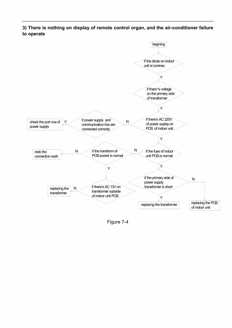
3) There is nothing on display of remote control organ, and the air-conditioner failureto operate
if there's AC 13V ontransformer subsideof indoor unit PCB.
if the transform ofPCB.socket is normal
replacing thetransformer
N
Y
redo theconnection work
check the port row ofpower supply
if power supply andcommunication line areconnected correctly
N
Y
replacing the transformer
if the primary side ofpower supplytransformer is short
Y
Y
replacing the PCB.of indoor unit
N
if there's AC 220Vof power suplay onPCB. of indoor unit
if the fuse of indoorunit PCB.is normal
N
N
Y
if there's voltageon the primary sideof tranaformer
Y
Y
if the diode on indoorunit is lumines
begining
Figure 7-4

11. Electrical Data: Outdoor unit:
Note:1.The communication terminal block to indoor cannot be connected to HT eletricity, or PCB will be damaged.2.Heater is optional according to different outdoor unit.3.Oxygen pump is optional.
Outdoor wiring diagram

Console type:
INDOOR WIRING DIAGRAMBOTTOM LOUVER MOTOR TOP LOUVER MOTOR
OPTIONAL BOARD
RECEIVING BOARD
AMBIENT TEMP. SENSOR
PIPING TEMP. SENS0R
BOTTOM FAN MOTOR
TOP FAN MOTOR
REMOTE CONTROL DETECTOR
POWER SUPPLY BOARD
TERMINAL BLOCK
SW3 and SW4 are used to choose the working state of the wired controller. The detailed information see the following:
Working state of the wire controllerSW3 SW4
If the controller power on, the indoor unit run according to the state on the controller;If the controller power off, the indoor unit run in the auto mode
Ignore the state on the controller and power off
Ignore the state on the controller and power off
The controller is able to be controlled
B : BLACK BL : BLUER : RED W : WHITEY/G: YELLOW/GREEN
NOTE PART IN DASH FRAME ARE OPTIONAL.
SW1 is an emergency key.SW2 is used to choose the working satate of douwn PG motor.
Connect To Outdoor UnitTo Power Supply(1PH,220-230V~,50Hz)
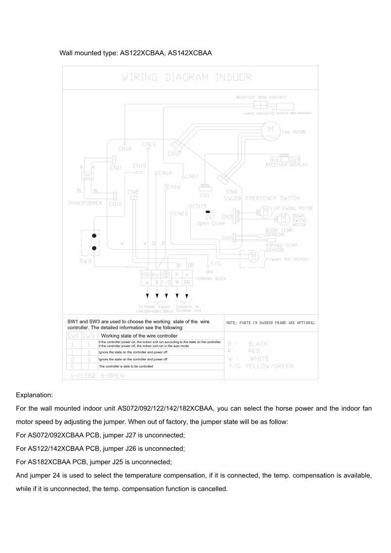
Wall mounted type: AS122XCBAA, AS142XCBAA
Ignore the state on the controller and power off
The controller is able to be controlled
Ignore the state on the controller and power off
if the controller power on, the indoor unit run according to the state on the controller;if the controller power off, the indoor unit run in the auto mode
Working state of the wire controller
SW1 and SW3 are used to choose the working state of the wirecontroller. The detailed information see the following:
Explanation:
For the wall mounted indoor unit AS072/092/122/142/182XCBAA, you can select the horse power and the indoor fan
motor speed by adjusting the jumper. When out of factory, the jumper state will be as follow:
For AS072/092XCBAA PCB, jumper J27 is unconnected;
For AS122/142XCBAA PCB, jumper J26 is unconnected;
For AS182XCBAA PCB, jumper J25 is unconnected;
And jumper 24 is used to select the temperature compensation, if it is connected, the temp. compensation is available,
while if it is unconnected, the temp. compensation function is cancelled.

Model: AS122XABAA
Remote control detector
Grouding
Grouding:To grouding of power
Note:Remote control detector is optional
Y/G
Wiring diagram of indoor unit
Transformer Signal receiver display
CN3 CN1
CN7
M
CN9CN2
CN8
S901
CN4
CN6
CN5CN16
Emergency switch
BL
B
M
Y/G: YELLOW/GREENBR: BROWN
R: RED B: BLACK
W: WHITE BL: BLUE
Terminal block
Singnal wire:To outdoor unit
Power:1PH, 220-230,50Hz
2(N)W
1(L)RBP
W B R
Y/GBRQ
BRLouver motor
Room temp. sensorHeat exch. sensor
Fanmotor

ceiling concealed type
3. P16 and P17 are used for room card function
CIRCUIT DIAGRAM OF INDOOR UNIT 0010573647
2. Central controller and fresh air are optional.
NOTE:1. Parts in dashed frame are optional. TO
OUTDOOR UNIT
W:WHITE B:BLACK R:RED Y:YELLOW OR:ORANGE BL:BLUE BR:BROWN Y/G:YELLOW/GREEN
POWER SUPPLY: 1PH,220-230V~,50Hz

cassette type
3. P16 and P17 are used for room card function
CIRCUIT DIAGRAM OF INDOOR UNIT
transformer
filter
motorwired controller
remote controller receiver central controller
receive board
float switch
swing motor pump motor
fan motor
fan capacitor
room temp. sensor
piping temp. sensor
TO OUTDOOR UNIT
POWER SUPPLY: 1PH,220-230V~,50Hz2. Central controller and fresh air are optional.
NOTE:1. Parts in dashed frame are factory optional .
W:WHITE B:BLACK R:RED Y:YELLOW OR:ORANGE BL:BLUE BR:BROWN Y/G:YELLOW/GREEN

Out
door
uni
t wiri
ng c
ircui
t:

Circ
uit d
iagr
am:
Wal
l mou
nted
type
:AS
122X
CB
AA
, AS
142X
CB
AA
C21
102
C9 104
C20
102
C17
102
low
er s
win
g m
otor
R36
10K
1
220V
L
1
220V
N
FUSE
1
T3.1
5A
C2
0.1u
F/27
5V
E1
2200
U/2
5V
E8
220U
/16V
+5
Vin
1
GND 2
Vou
t3
W1
7805
C7 104
RV1
S14K
350
PTC4
1
IRQ
2
RST
3
PTF0
/TA
CH2
4
PTF1
/TA
CH3
5
PTF2
/TA
CH2
6
PTF3
/TA
CH3
7
PTF4
/TA
CH0
8
NC
9
PTF7
10
PTF5
/TBC
H1
11
PTF6
12
PTE0
/TX
D13
PTE1
/RX
D14
PTE2
/TA
CH0
15
PTE3
/TA
CH1
16
PTE4
/SS
17
PTE5
/MIS
O18
PTE6
/MO
SI19
PTE7
/SPS
CK20
VSS
21
VD
D22
PTG
0/K
BD0
23
PTG
1/K
BD1
24
PTG
2/K
BD2
25
PA0
26
PA1
27
PA2
28
PA3
29
PA4
30
PA5
31
PA6
32PA
733
ATB
0/A
TD0
34A
TB1/
ATD
135
ATB
2/A
TD2
36A
TB3/
ATD
337
ATB
4/A
TD4
38A
TB5/
ATD
539
ATB
6/A
TD6
40A
TB7/
ATD
741
PTD
042
PTD
143
VD
DA
REF
44A
VSS
/VRE
FL45
PTD
246
PTD
347
PTH
0/K
BD3
48PT
H1/
KBD
449
PTD
4/TB
CLK
50PT
D5
51PT
D6/
TACL
K52
PTD
753
VRE
FH54
VD
DA
55V
SSA
56CG
MX
FC57
OSC
258
OSC
159
PTC0
60PT
C161
PTC2
/MCL
K62
PTC3
63PT
C564
AB3
2
IC1
908A
B32
R13
10K
+5
C24
102
R58
22K
R19
1K
R42
10K
+5
N2
2SC2
412K
N3
2SC2
412K
rem
ote
com
mun
icat
ion
12CN
6
R29
1K
R15
1K
+5
com
mun
icat
ion
betw
een
indo
or a
nd o
utdo
or
IC3
TLP5
21
12
CN8
LED
1
1 2 3
CN4
+5
C3 103
R44
51K
R31K
IC7
TLP3
526
1 2 3
CN12
C1
1.2UF 450V
1
220V
L
R2 330
RC10.01uF*120
12
CN7
+5
R38
10K
3 45678
1 2IC
624
C01
+5
E6
4.7U
F/50
V
E7 4.7U
F/50
V
1234
CN5
R26
1K
R25
1K
R59
3.3K
1%
R60
20K
1%
K1
JQ1a
-12V
+5
R41
10K
PG o
utpu
t
nega
tive
ion
fresh
air
ÊÒÎÂ
Å̹Ü
auto
-che
ck
TXD
RXD
C6 104
R22
1K
R21
1K
C23
102
C19
102
C18
102
+5
12345678 9
10111213141516
IC5
2003
12345
12345
CN3
C DBA
C DBA
uppe
r sw
ing
mot
or
+12
+12
+12
+5
C12
104
+5
E4
2.2u
/16V
C8
104+5
C14
104
CN14
CN13
BZ1
R61
100
R56
4.7K
+5
CN11
R4 10K
À¼
μÆÂ
ÌμÆ
ºìμÆ
pow
er in
dica
tor
timer
indi
cato
r
run
indi
cato
rhe
alth
indi
cato
r
P1 2SB1
197K
R46
470
R35
10k
+5
P2 2SB1
197K
R47
470
R34
10k
+5
P3 2SB1
197K
R48
470
R33
10k
+5
+12
R57
22K
R14
4.7K
+5
R18
1K
12SW2
R27
1KR3
210
K
emer
genc
y
nega
tive
ion
fresh
air
N4
2SC2
412K
R12
10K
R52
470
R51
470
R50
470
R49
470
R20
10K
SW1
+5
LED
101
GND+5V
IR
HS0
038A
2M
PD1
C101
4.7U
/16V
R101
10K
HEALTH
RUN
IR
+5V
GND
POWER
TIME
RED
GREEN
BLUE
CN101
R102
100
LED
102
LED
104
LED
103
wal
l mou
nted
LED
boa
rd c
ircui
t
C25
102
BLUE
GREEN
RED LED
105
TRIC
OLO
R
N1
2SC2
412K
R37
10K
+5
R54
4.7K
C510
4
R16
1K
N5
2SC2
412K
R610
K
N8
2SC2
412K
R910
K
N7
2SC2
412K
R8 10K
N6
2SC2
412K
R7 10K
N9
2SC2
412K
R40
10K
+12
R43
10K
VD
1
4148
R53
1M
CN17
+5
+12v
D2
1N41
48
1234
CN9
+5
+5
TXD
RXD
R30
1K
R39
10K
+12
P42S
B118
2xf
_1
E5 100u
/16v
C16
103
C11
104
C15
103
E3 100u
/16V
C13
104
R23
10K
+12
SCL
SDA
1
220V
N
R10
10K
R5 10K
XT1
4M
C10
102
RA1
J24-
J27
C22
102
D4
1N40
07
IC2
TLP5
21-1
+5
1P18
2501
CN16
250
R45
250
R3 680
R1 100K
/2W
R62
200K
R17 1K
live
wire
neut
ral w
ire
E2 2.2u
F
C410
3
12CN
2IC
4
TLP5
21
R11
10K
CN18
123CN10
B2D
4 1N40
07
R28
1KR3
110
K
HEALTH
RUN
IR
+5V
GND
POWER
TIME
RED
GREEN
BLUE
CN1
J24
J25
J26
J27
mod
el
07091218--
----
--
R55
4.7K
ON
ON
ON
ON
ON
ON
ON
ON
ON
ON
ON
ON

Circ
uit D
iagr
am
Indo
orun
itM
odel
:AS
092X
AB
AA
, AS1
22XA
BA
A

Con
sole
type
(pow
er b
oard
):
12
34
56
ABCD
65
43
21
D C B A
+12V
Vin
1
GND 2
Vou
t3
IC3
7805
C11
100u
F/16
V
+5
LED
1G
REEN
IC4
P521
GN
DS
C3 2.2n
F/1K
V
C4
0.1u
F/50
V
C5 2.2n
F Y
1
D5
UF4
005
D6
MU
R410
100
V4A
1 2
3 4
T
135-
265V
AC
C2 22uF
400
V
C6 1000
uF 2
5VC8 47
0uF/
25V
L2 3.3u
H 2
A
C1
0.1u
F 25
0VA
C X
1
VR1
550N
R-14
D
R2 200
GN
DS
D7
1N40
07
C12
104/
63V
C922
0uF/
16V
C10
104/
63V
+5
C13
103
D8
1N41
48
+12V
+5V
GN
D
ZERO
GN
DS
IC2
P521
B2P3
-VH
CN10
2
LX1
15m
H
BP1
S2
S3
EN4
D5
NC
6
S7
S8
IC1
TNY
268P
12
CN10
1
R1
68K
2W
NTC
5.0
R4 200K
/2W
R7 3K
R5 10K
1 2 3 4 5 6 7 8
CN10
2
R3 1.5K
Z1 11V
D1
IN40
07D
2IN
4007
D3
IN40
07
D4
IN40
07
Q1
9014
GN
DS
+5
R6 10K
C7 470u
F/25
V

12
34
56
ABCD
65
43
21
D C B A
+12V
Vin
1
GND 2
Vou
t3
IC3
7805
C11
100u
F/16
V
+5
LED
1G
REEN
IC4
P521
GN
DS
C3 2.2n
F/1K
V
C4
0.1u
F/50
V
C5 2.2n
F Y
1
D5
UF4
005
D6
MU
R410
100
V4A
1 2
3 4
T
135-
265V
AC
C2 22uF
400
V
C6 1000
uF 2
5VC8 47
0uF/
25V
L2 3.3u
H 2
A
C1
0.1u
F 25
0VA
C X
1
VR1
550N
R-14
D
R2 200
GN
DS
D7
1N40
07
C12
104/
63V
C922
0uF/
16V
C10
104/
63V
+5
C13
103
D8
1N41
48
+12V
+5V
GN
D
ZERO
GN
DS
IC2
P521
B2P3
-VH
CN10
2
LX1
15m
H
BP1
S2
S3
EN4
D5
NC
6
S7
S8
IC1
TNY
268P
12
CN10
1
R1
68K
2W
NTC
5.0
R4 200K
/2W
R7 3K
R5 10K
1 2 3 4 5 6 7 8
CN10
2
R3 1.5K
Z1 11V
D1
IN40
07D
2IN
4007
D3
IN40
07
D4
IN40
07
Q1
9014
GN
DS
+5
R6 10K
C7 470u
F/25
V
Con
sole
type
(con
trol b
oard
):

Con
sole
type
(sel
ect b
oard
):
12345678
CN1
CON
8
R110
KR2
10K
R310
K
R4 220
R5 220
R6 220
R7 10K
Q1
9013
Q2
9013
Q3
9013
+5
SW1
R8 10K
R9 330
C24.
7UF/
50V
OUT
VCC GNDIC
3
LED
1LE
D2
LED
3LE
D
C1 102
Indi
catio
n bo
ard
circ
uit d
iagr
a
12
CN
2
+5
SW2
SW3
R11
5.1K
R12
10K
R13
20K
sele
ctio
n bo
ard
circ
uit d
iagr
am
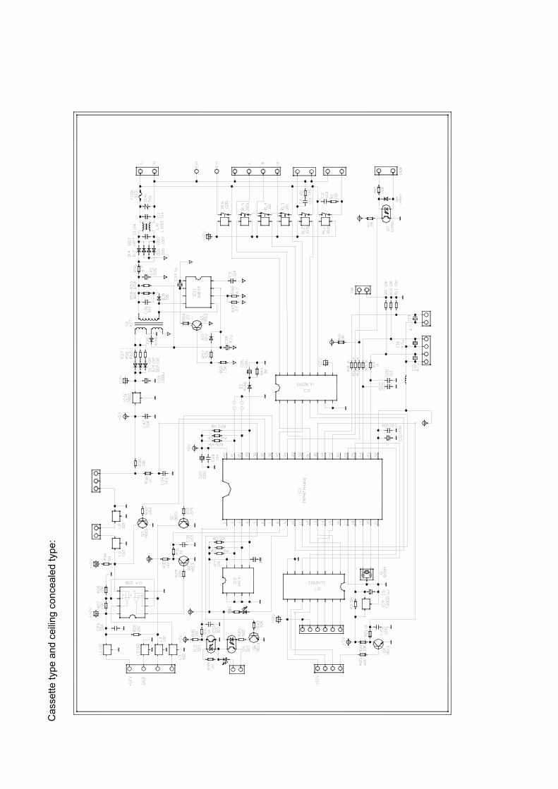
Cas
sette
type
and
cei
ling
conc
eale
d ty
pe:

Exploded views:Outdoor unit:

No.Spare partsnumber Spare parts description in English Qty. Model Failure rate
the proportion ofthe spare-partstock Remark
1 001A0100122 Front guard assy 2 AU422XIBAA 0.0000% 0.0000% X
2 001A1301971 Plate for maintain 1 AU422XIBAA 0.0000% 0.0000% X
3 001A1301640 Front Panel(left) 1 AU422XIBAA 0.0000% 0.0000% X
4 001A5402022 Axial fan 2 AU422XIBAA 0.0200% 0.0240% *
5 001A3000201 Fan motor 2 AU422XIBAA 0.0200% 0.0240% *
6 001A0100498 Motor mounting plate 1 AU422XIBAA 0.0000% 0.0000% X
7 001A17421215 PE 1 AU422XIBAA 0.0000% 0.0000% X
8 001A1301469 Fixing plate 1 AU422XIBAA 0.0000% 0.0000% X
9 0010751102 Condenser assy 1 AU422XIBAA 0.0000% 0.0000% X
10 001A17341206 Damping pad 1 AU422XIBAA 0.0000% 0.0000% X
11 001A2500094 coil A of solenoid valve 1 AU422XIBAA 0.0100% 0.0120% *
12 001A5736055 clip for sensor 1 AU422XIBAA 0.0000% 0.0000% X
13 0010451343 ambient temp. sensor 1 AU422XIBAA 0.0100% 0.0120%
14 001A0100827 Top cover assy. 1 AU422XIBAA 0.0000% 0.0000% X
15 001A0100767 Guard for heat exchanger 1 AU422XIBAA 0.0000% 0.0000% X
16 001A0100494 Slide plate(right) 1 AU422XIBAA 0.0000% 0.0000% X
17 001A1436160 Handle 1 AU422XIBAA 0.0000% 0.0000% X
18 001A1301465 Fix plate 1 AU422XIBAA 0.0000% 0.0000% X
19 0010450243 A system coil temp. sensor 1 AU422XIBAA 0.0200% 0.0240% *
20 0010451343 B system coil temp. sensor 1 AU422XIBAA 0.0200% 0.0240% *
21 0010450398 A system discharging temp. sensor 1 AU422XIBAA 0.0200% 0.0240% *
22 0010451344 B system discharging temp. sensor 1 AU422XIBAA 0.0200% 0.0240% *
23 0010450755 Solenoid valve coil 1 AU422XIBAA 0.0000% 0.0000% X
23 0010450757 Solenoid valve coil 1 AU422XIBAA 0.0000% 0.0000% X
23 0010451193 Solenoid valve coil 1 AU422XIBAA 0.0000% 0.0000% X
23 0010451195 Solenoid valve coil 1 AU422XIBAA 0.0000% 0.0000% X
24 001A2500095 Solenoid valve coil B 1 AU422XIBAA 0.0000% 0.0000% X
25 0010701958 Compressor 2 AU422XIBAA 0.0600% 0.0720% *
26 0010751055 (3-way)stop valve 1 AU422XIBAA 0.0000% 0.0000% X
27 0010700252 (2-way)stop valve 1 AU422XIBAA 0.0000% 0.0000% X
28 0010751056 (2-way)stop valve 1 AU422XIBAA 0.0000% 0.0000% X
29 001A1301119 Valve plate 1 AU422XIBAA 0.0000% 0.0000% X
30 001A13011200 compressor splint 1 AU422XIBAA 0.0000% 0.0000% X
31 0010151600 bottom plate 1 AU422XIBAA 0.0000% 0.0000% X
32 0010150090 compressor supporting plate 1 AU422XIBAA 0.0000% 0.0000% X
33 001A3600030 running capacitor 2 AU422XIBAA 0.2000% 0.2400% *
34 001A0100496 partial plate 1 AU422XIBAA 0.0000% 0.0000% X
Parts list

35 001A3900161 AC contactor 2 AU422XIBAA 0.2000% 0.2400% *
36 0010150084 electric box (horizontal) 1 AU422XIBAA 0.0000% 0.0000% X
37 001A3600018 fan capacitor 2 AU422XIBAA 0.2000% 0.2400% *
38 0010150138 electric box (vertical) 1 AU422XIBAA 0.0000% 0.0000% X
39 001A4000110 power wiring block 1 AU422XIBAA 0.0000% 0.0000% X
40 0010451214 PCB 1 AU422XIBAA 0.2000% 0.2400% *
41 0010450305 signal wiring block 1 AU422XIBAA 0.0000% 0.0000% X
42 001A4000111 terminal block 1 AU422XIBAA 0.0000% 0.0000% X
43 001A3800066 transformer 1 AU422XIBAA 0.2000% 0.2400% X
4,not need provided :The spare-part which is seldom damaged or the maintenance man could not maitmains.The spare parts may be airfreighted by the factory if they were damaged.The customer nees not stock in the spare-part warehouse,should be marked with " x ".
5,Above should be improved accord with the reply of the market half a year per time.6.The spare parts price on net is FOB Qingdao term.
1,The failer rate and the proportion of the spare-part stock are regarded as the reference of the stock for spare-parts;The first timeshould be stocked accroded with the proportion of the spare-parts,and it should be adjusted with the actual quantity 3 months later.
2,easy-damaged;The spare-part which is often damaged and the customer must stock in the spare-parts warehouse,and should bemarked with"*"
3,possible damaged:The spare-part which is not often damaged like the easy damaged one and the customer may stock in the spare-part warehouse accord with the actual case,should be marked with " ".


No. Spare parts numberSpare parts description inEnglish Qty. Model Failure rate
the proportion of thespare-part stock Remark
1 001A0100543 Front grill 1 AS122XABAA 0.00% 0.000% ×2 001A0100943 Front panel 1 AS122XABAA 0.00% 0.000% ×3 001A2400080 Air filter 1 AS122XABAA 0.00% 0.000% ×4 001A2400080 Air filter 1 AS122XABAA 0.00% 0.000% ×5 001A5313003 Screw 4 AS122XABAA 0.00% 0.000% ×6 001A0400129 Heat exchanger 1 AS122XABAA 0.01% 0.012%7 001A0300005 Bearing 1 AS122XABAA 0.00% 0.000% ×8 0010202227 Fan 1 AS122XABAA 0.02% 0.024% *9 001A5002088 Screw 1 AS122XABAA 0.00% 0.000% ×
10 001A0100276 Bottom plate 1 AS122XABAA 0.00% 0.000% ×11 001A1301021 Mounting plate 1 AS122XABAA 0.00% 0.000% ×12 001A3000088 Motor 1 AS122XABAA 0.02% 0.024% *13 001A1431717 Motor cover 1 AS122XABAA 0.00% 0.000% ×14 001A4000122 terminal block 1 AS122XABAA 0.00% 0.000% ×15 001A1431693 Control box 1 AS122XABAA 0.00% 0.000% ×16 0010450610 PC board 1 AS122XABAA 0.04% 0.048% *17 001A3000008 Swing motor 2 AS122XABAA 0.02% 0.024% *18 001A1231140 Flap 1 AS122XABAA 0.00% 0.000% ×19 001A2239006A Cushion 1 AS122XABAA 0.00% 0.000% ×20 001A0900104 Drain pan 1 AS122XABAA 0.00% 0.000% ×21 001A0900011 Drain hose 1 AS122XABAA 0.00% 0.000% ×22 001B0500412 Suction pipe assy 1 AS122XABAA 0.00% 0.000% ×23 001B0500413 Discharge pipe tube 1 AS122XABAA 0.00% 0.000% ×24 001A1741744 Heat insulation tube 1 AS122XABAA 0.00% 0.000% ×25 001A3800065 transformer 1 AS122XABAA 0.02% 0.024% *
4,not need provided :The spare-part which is seldom damaged or the maintenance man could not maitmains.The spareparts may be air freighted by the factory if they were damaged.The customer nees not stock in the spare-partwarehouse,should be marked with " x ".
5,Above should be improved accord with the reply of the market half a year per time.6.The spare parts price on net is FOB Qingdao term.
Parts list
1,The failer rate and the proportion of the spare-part stock are regarded as the reference of the stock for spare-parts;Thefirst time should be stocked accroded with the proportion of the spare-parts,and it should be adjusted with the actualquantity 3 months later.
2,easy-damaged;The spare-part which is often damaged and the customer must stock in the spare-parts warehouse,andshould be marked with"*"
3,possible damaged:The spare-part which is not often damaged like the easy damaged one and the customer may stockin the spare-part warehouse accord with the actual case,should be marked with " ".

&�
&�
&�

No. Spare parts numberSpare parts description inEnglish Qty. Model Failure rate
the proportion of thespare-part stock Remark
1 0010202192 Front grill 1 AS122XCBAA 0.00% 0.000% ×2 0010802130 Front panel 1 AS122XCBAA 0.00% 0.000% ×3 0010202204 Air filter (left) 1 AS122XCBAA 0.00% 0.000% ×4 0010202205 Air filter (right) 1 AS122XCBAA 0.00% 0.000% ×5 001A5313003 Screw 4 AS122XCBAA 0.00% 0.000% ×6 0010704200 Heat exchanger 1 AS122XCBAA 0.01% 0.012%7 001A0300005 Bearing 1 AS122XCBAA 0.00% 0.000% ×8 0010202415 Fan 1 AS122XCBAA 0.02% 0.024% *9 001A5002088 Screw 1 AS122XCBAA 0.00% 0.000% ×
10 001A0100206 Bottom plate 1 AS122XCBAA 0.00% 0.000% ×11 001A1301216 Mounting plate 1 AS122XCBAA 0.00% 0.000% ×12 001A3000052 Motor 1 AS122XCBAA 0.02% 0.024% *13 001A1431372 Motor cover 1 AS122XCBAA 0.00% 0.000% ×14 0010401858 terminal block 1 AS122XCBAA 0.00% 0.000% ×15 0010202198 Control box 1 AS122XCBAA 0.00% 0.000% ×16 0010451213 PC board 1 AS122XCBAA 0.04% 0.048% *17 0010402433 Swing motor 2 AS122XCBAA 0.02% 0.024% *18 001A1431028 Flap 1 AS122XCBAA 0.00% 0.000% ×19 001A2239006A Cushion 1 AS122XCBAA 0.00% 0.000% ×20 0010802133 Drain pan 1 AS122XCBAA 0.00% 0.000% ×21 001A0900011 Drain hose 1 AS122XCBAA 0.00% 0.000% ×22 0010703601 Suction pipe assy 1 AS122XCBAA 0.00% 0.000% ×23 0010703607 Discharge pipe tube 1 AS122XCBAA 0.00% 0.000% ×24 001A1741744 Heat insulation tube 1 AS122XCBAA 0.00% 0.000% ×25 0010202215 display board 1 AS122XCBAA 0.00% 0.000% ×26 0010402315 transformer 1 AS122XCBAA 0.02% 0.024% *27 0010802132 display board assembly 1 AS122XCBAA 0.00% 0.000% ×
4,not need provided :The spare-part which is seldom damaged or the maintenance man could not maitmains.The spareparts may be air freighted by the factory if they were damaged.The customer nees not stock in the spare-partwarehouse,should be marked with " x ".
5,Above should be improved accord with the reply of the market half a year per time.6.The spare parts price on net is FOB Qingdao term.
Parts list
1,The failer rate and the proportion of the spare-part stock are regarded as the reference of the stock for spare-parts;Thefirst time should be stocked accroded with the proportion of the spare-parts,and it should be adjusted with the actualquantity 3 months later.
2,easy-damaged;The spare-part which is often damaged and the customer must stock in the spare-parts warehouse,andshould be marked with"*"
3,possible damaged:The spare-part which is not often damaged like the easy damaged one and the customer may stockin the spare-part warehouse accord with the actual case,should be marked with " ".
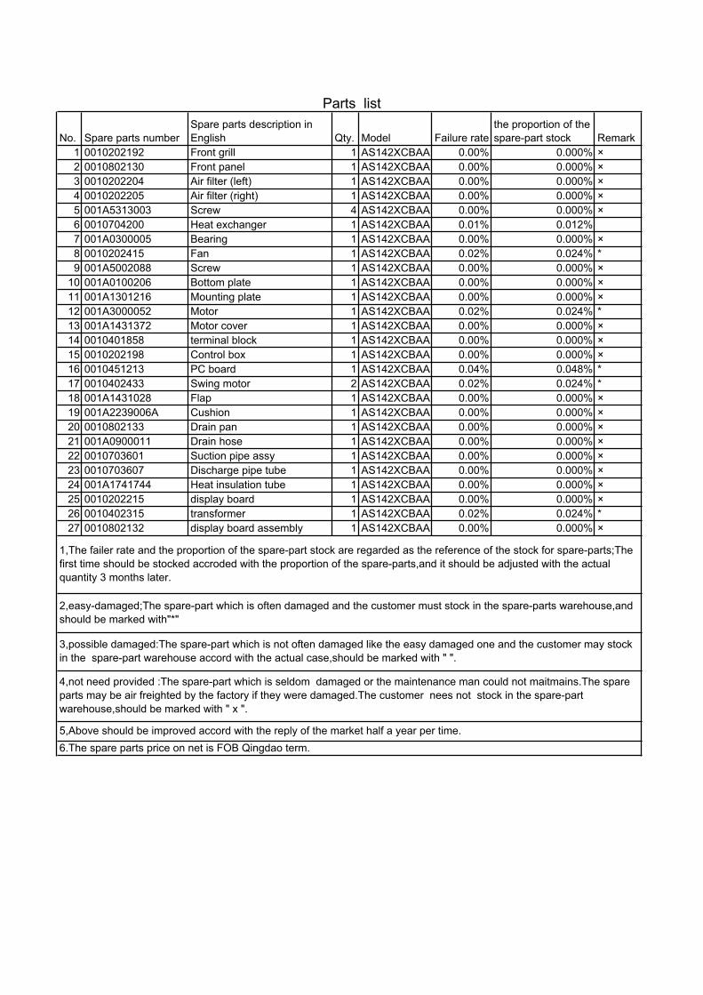
No. Spare parts numberSpare parts description inEnglish Qty. Model Failure rate
the proportion of thespare-part stock Remark
1 0010202192 Front grill 1 AS142XCBAA 0.00% 0.000% ×2 0010802130 Front panel 1 AS142XCBAA 0.00% 0.000% ×3 0010202204 Air filter (left) 1 AS142XCBAA 0.00% 0.000% ×4 0010202205 Air filter (right) 1 AS142XCBAA 0.00% 0.000% ×5 001A5313003 Screw 4 AS142XCBAA 0.00% 0.000% ×6 0010704200 Heat exchanger 1 AS142XCBAA 0.01% 0.012%7 001A0300005 Bearing 1 AS142XCBAA 0.00% 0.000% ×8 0010202415 Fan 1 AS142XCBAA 0.02% 0.024% *9 001A5002088 Screw 1 AS142XCBAA 0.00% 0.000% ×
10 001A0100206 Bottom plate 1 AS142XCBAA 0.00% 0.000% ×11 001A1301216 Mounting plate 1 AS142XCBAA 0.00% 0.000% ×12 001A3000052 Motor 1 AS142XCBAA 0.02% 0.024% *13 001A1431372 Motor cover 1 AS142XCBAA 0.00% 0.000% ×14 0010401858 terminal block 1 AS142XCBAA 0.00% 0.000% ×15 0010202198 Control box 1 AS142XCBAA 0.00% 0.000% ×16 0010451213 PC board 1 AS142XCBAA 0.04% 0.048% *17 0010402433 Swing motor 2 AS142XCBAA 0.02% 0.024% *18 001A1431028 Flap 1 AS142XCBAA 0.00% 0.000% ×19 001A2239006A Cushion 1 AS142XCBAA 0.00% 0.000% ×20 0010802133 Drain pan 1 AS142XCBAA 0.00% 0.000% ×21 001A0900011 Drain hose 1 AS142XCBAA 0.00% 0.000% ×22 0010703601 Suction pipe assy 1 AS142XCBAA 0.00% 0.000% ×23 0010703607 Discharge pipe tube 1 AS142XCBAA 0.00% 0.000% ×24 001A1741744 Heat insulation tube 1 AS142XCBAA 0.00% 0.000% ×25 0010202215 display board 1 AS142XCBAA 0.00% 0.000% ×26 0010402315 transformer 1 AS142XCBAA 0.02% 0.024% *27 0010802132 display board assembly 1 AS142XCBAA 0.00% 0.000% ×
4,not need provided :The spare-part which is seldom damaged or the maintenance man could not maitmains.The spareparts may be air freighted by the factory if they were damaged.The customer nees not stock in the spare-partwarehouse,should be marked with " x ".
5,Above should be improved accord with the reply of the market half a year per time.6.The spare parts price on net is FOB Qingdao term.
Parts list
1,The failer rate and the proportion of the spare-part stock are regarded as the reference of the stock for spare-parts;Thefirst time should be stocked accroded with the proportion of the spare-parts,and it should be adjusted with the actualquantity 3 months later.
2,easy-damaged;The spare-part which is often damaged and the customer must stock in the spare-parts warehouse,andshould be marked with"*"
3,possible damaged:The spare-part which is not often damaged like the easy damaged one and the customer may stockin the spare-part warehouse accord with the actual case,should be marked with " ".


No.Spare partsnumber
Spare parts description inEnglish Qty. Model Failure rate
the proportion ofthe spare-partstock Remark
1 0010800954 front grill 1 AF122XCBAA 0.0000% 0.0000% X2 0010201169 air filter 1 AF122XCBAA 0.0000% 0.0000% X3 0010201288 button 1 AF122XCBAA 0.0000% 0.0000% X4 0010800923 front panel 1 AF122XCBAA 0.0000% 0.0000% X5 0010753052 heat exchanger 1 AF122XCBAA 0.0100% 0.0120%6 001A3900059 temperature sensor 1 AF122XCBAA 0.0100% 0.0120%7 0010800928 motor cover 1 AF122XCBAA 0.0000% 0.0000% X8 0010201176 bearing 1 AF122XCBAA 0.0000% 0.0000% X9 0010201176 bearing 1 AF122XCBAA 0.0000% 0.0000% X
10 0010201191 flap 1 AF122XCBAA 0.0000% 0.0000% X11 0010800930 upper air outlet assy 1 AF122XCBAA 0.0000% 0.0000% X12 0010800924 bottom plate 1 AF122XCBAA 0.0000% 0.0000% X13 0010800932 plate cushion 1 AF122XCBAA 0.0000% 0.0000% X14 0010100571 back panel 1 AF122XCBAA 0.0000% 0.0000% X15 001A5002008 screw 4 AF122XCBAA 0.0000% 0.0000% X16 001A5002116 screw 5 AF122XCBAA 0.0000% 0.0000% X17 001A5401031 screw washer 5 AF122XCBAA 0.0000% 0.0000% X18 001A5002118 screw 2 AF122XCBAA 0.0000% 0.0000% X19 0010400935 swing motor 1 AF122XCBAA 0.0200% 0.0240% *20 0010400933 indoor motor 1 1 AF122XCBAA 0.0200% 0.0240% *21 0010850276 display board 1 AF122XCBAA 0.0000% 0.0000% X22 0010800928 motor cover 1 AF122XCBAA 0.0000% 0.0000% X23 0010100572 control box shell 1 AF122XCBAA 0.0000% 0.0000% X24 0010201188 control box 1 AF122XCBAA 0.0000% 0.0000% X25 0010451212 main board 1 AF122XCBAA 0.0100% 0.0120%26 0010451212*1 power board 1 AF122XCBAA 0.0100% 0.0120%27 0010201189 service cover 1 AF122XCBAA 0.0000% 0.0000% X28 0010451333 terminal block 1 AF122XCBAA 0.0100% 0.0120%29 0010201269 wiring clamp 1 AF122XCBAA 0.0000% 0.0000% X30 001A5002099 screw 3 AF122XCBAA 0.0000% 0.0000% X31 001A5002236 screw 3 AF122XCBAA 0.0000% 0.0000% X32 0010201275 hand switch 1 AF122XCBAA 0.0000% 0.0000% X33 0010451212*2 select board 1 AF122XCBAA 0.0000% 0.0000% X34 0010400934 indoor motor 2 1 AF122XCBAA 0.0200% 0.0240% *35 0010201209 flap2 1 AF122XCBAA 0.0000% 0.0000% X36 0010800931 lower air outlet assy 1 AF122XCBAA 0.0000% 0.0000% X37 0010201184 lower fan 1 AF122XCBAA 0.0200% 0.0240% *38 0010201175 upper fan 1 AF122XCBAA 0.0200% 0.0240% *39 0010400936 swing motor 1 AF122XCBAA 0.0200% 0.0240% *40 0010201281 cover panel 1 AF122XCBAA 0.0000% 0.0000% X41 001A5002236 screw 2 AF122XCBAA 0.0000% 0.0000% X
4,not need provided :The spare-part which is seldom damaged or the maintenance man could not maitmains.The spare partsmay be air freighted by the factory if they were damaged.The customer nees not stock in the spare-part warehouse,should bemarked with " x ".5,Above should be improved accord with the reply of the market half a year per time.6.The spare parts price on net is FOB Qingdao term.
Parts list
1,The failer rate and the proportion of the spare-part stock are regarded as the reference of the stock for spare-parts;The firsttime should be stocked accroded with the proportion of the spare-parts,and it should be adjusted with the actual quantity 3months later.
2,easy-damaged;The spare-part which is often damaged and the customer must stock in the spare-parts warehouse,andshould be marked with"*"
3,possible damaged:The spare-part which is not often damaged like the easy damaged one and the customer may stock in thespare-part warehouse accord with the actual case,should be marked with " ".
AF12 and AF14 are the same:

Exploded View
20
21

No. Spare parts numberSpare parts description inEnglish Qty. Model
Failurerate
the proportionof the spare-part stock Remark
1 *0010851501.1 fan 2 AE122XCBAA 0.0200% 0.0240% *2 *0010851501.2 scroll case 2 AE122XCBAA 0.0000% 0.0000% X3 *0010851501.3 fan motor 1 AE122XCBAA 0.0200% 0.0240% *4 0010451521 wire remote controller 1 AE122XCBAA 0.0100% 0.0120%5 *0010851501.4 evaporator 1 AE122XCBAA 0.0000% 0.0000% X6 *0010851501.5 shell 1 AE122XCBAA 0.0000% 0.0000% X7 001A3900006 gas pipe temperature sensor 1 AE122XCBAA 0.0100% 0.0120%
20 / / / AE122XCBAA / / /8 *0010851501.6 PMV 1 AE122XCBAA 0.0100% 0.0120%
21 *0010851501.7 PMV coil 1 AE122XCBAA 0.0000% 0.0000% X
9 *0010851501.8subsiduary drain pan supportbracket 1 AE122XCBAA 0.0000% 0.0000% X
10 *0010851501.9 electricial box support bracket 1 AE122XCBAA 0.0000% 0.0000% X11 001A5745116 clip plate 2 AE122XCBAA 0.0000% 0.0000% X12 0010450322 terminal block 1 AE122XCBAA 0.0100% 0.0120%13 0010451847 indoor PCB 1 AE122XCBAA 0.0200% 0.0240% *14 0010250135 electricial box cover 1 AE122XCBAA 0.0000% 0.0000% X15 0010250134 electricial box 1 AE122XCBAA 0.0100% 0.0120%16 *0010851501.10 subsiduary drain pan 1 AE122XCBAA 0.0000% 0.0000% X17 *0010851501.11 drain pan 1 AE122XCBAA 0.0000% 0.0000% X18 *0010851501.12 outlet airflow flange 1 AE122XCBAA 0.0000% 0.0000% X19 *0010851501.13 motor mix ring 1 AE122XCBAA 0.0000% 0.0000% X
4,not need provided :The spare-part which is seldom damaged or the maintenance man could not maitmains.The spareparts may be air freighted by the factory if they were damaged.The customer nees not stock in the spare-partwarehouse,should be marked with " x ".5,Above should be improved accord with the reply of the market half a year per time.6.The spare parts price on net is FOB Qingdao term.
Parts list
1,The failer rate and the proportion of the spare-part stock are regarded as the reference of the stock for spare-parts;Thefirst time should be stocked accroded with the proportion of the spare-parts,and it should be adjusted with the actualquantity 3 months later.
2,easy-damaged;The spare-part which is often damaged and the customer must stock in the spare-parts warehouse,andshould be marked with"*"
3,possible damaged:The spare-part which is not often damaged like the easy damaged one and the customer may stockin the spare-part warehouse accord with the actual case,should be marked with " ".

No. Spare parts numberSpare parts description inEnglish Qty. Model
Failurerate
the proportion ofthe spare-partstock Remark
1 *0010851502.1 fan 2 AE142XCBAA 0.0200% 0.0240% *2 *0010851502.2 scroll case 2 AE142XCBAA 0.0000% 0.0000% X3 *0010851502.3 fan motor 1 AE142XCBAA 0.0200% 0.0240% *4 0010451521 wire remote controller 1 AE142XCBAA 0.0100% 0.0120%5 *0010851502.4 evaporator 1 AE142XCBAA 0.0000% 0.0000% X6 *0010851502.5 shell 1 AE142XCBAA 0.0000% 0.0000% X7 001A3900006 gas pipe temperature sensor 1 AE142XCBAA 0.0100% 0.0120%
20 / / / AE142XCBAA / / /8 *0010851502.6 PMV 1 AE142XCBAA 0.0100% 0.0120%
21 *0010851502.7 PMV coil 1 AE142XCBAA 0.0000% 0.0000% X
9 *0010851502.8subsiduary drain pan supportbracket 1 AE142XCBAA 0.0000% 0.0000% X
10 *0010851502.9 electricial box support bracket 1 AE142XCBAA 0.0000% 0.0000% X11 001A5745116 clip plate 2 AE142XCBAA 0.0000% 0.0000% X12 0010450322 terminal block 1 AE142XCBAA 0.0100% 0.0120%13 0010451847 indoor PCB 1 AE142XCBAA 0.0200% 0.0240% *14 0010250135 electricial box cover 1 AE142XCBAA 0.0000% 0.0000% X15 0010250134 electricial box 1 AE142XCBAA 0.0100% 0.0120%16 *0010851502.10 subsiduary drain pan 1 AE142XCBAA 0.0000% 0.0000% X17 *0010851502.11 drain pan 1 AE142XCBAA 0.0000% 0.0000% X18 *0010851502.12 outlet airflow flange 1 AE142XCBAA 0.0000% 0.0000% X19 *0010851502.13 motor mix ring 1 AE142XCBAA 0.0000% 0.0000% X
4,not need provided :The spare-part which is seldom damaged or the maintenance man could not maitmains.The spareparts may be air freighted by the factory if they were damaged.The customer needs not stock in the spare-partwarehouse,should be marked with " x ".
5,Above should be improved accord with the reply of the market half a year per time.6.The spare parts price on net is FOB Qingdao term.
Parts list
1,The failer rate and the proportion of the spare-part stock are regarded as the reference of the stock for spare-parts;Thefirst time should be stocked accroded with the proportion of the spare-parts,and it should be adjusted with the actualquantity 3 months later.
2,easy-damaged;The spare-part which is often damaged and the customer must stock in the spare-parts warehouse,andshould be marked with"*"
3,possible damaged:The spare-part which is not often damaged like the easy damaged one and the customer may stockin the spare-part warehouse accord with the actual case,should be marked with " ".

No. Spare parts number Spare parts description in English Qty. Model Failure rate
the proportionof the spare-part stock Remark
1 *0010851572.1 fan 2 AE212XCBAA 0.0200% 0.0240% *
2 *0010851572.2 scroll case 2 AE212XCBAA 0.0000% 0.0000% X
3 *0010851572.3 fan motor 1 AE212XCBAA 0.0200% 0.0240% *
4 0010451521 wire remote controller 1 AE212XCBAA 0.0100% 0.0120%
5 *0010851572.4 evaporator 1 AE212XCBAA 0.0000% 0.0000% X
6 *0010851572.5 shell 1 AE212XCBAA 0.0000% 0.0000% X7 001A3900006 gas pipe temperature sensor 1 AE212XCBAA 0.0100% 0.0120%
20 001A3900005 sensor 1 AE212XCBAA 0.0100% 0.0120%
8 *0010851572.6 PMV 1 AE212XCBAA 0.0100% 0.0120%
21 *0010851572.7 PMV coil 1 AE212XCBAA 0.0000% 0.0000% X9 *0010851572.8 subsiduary drain pan support bracket 1 AE212XCBAA 0.0000% 0.0000% X
10 *0010851572.9 electricial box support bracket 1 AE212XCBAA 0.0000% 0.0000% X
11 001A5745116 clip plate 2 AE212XCBAA 0.0000% 0.0000% X
12 0010450322 terminal block 1 AE212XCBAA 0.0100% 0.0120%
13 0010451847 indoor PCB 1 AE212XCBAA 0.0200% 0.0240% *
14 0010250135 electricial box cover 1 AE212XCBAA 0.0000% 0.0000% X
15 0010250134 electricial box 1 AE212XCBAA 0.0100% 0.0120%
16 *0010851572.10 subsiduary drain pan 1 AE212XCBAA 0.0000% 0.0000% X
17 *0010851572.11 drain pan 1 AE212XCBAA 0.0000% 0.0000% X
18 *0010851572.12 outlet airflow flange 1 AE212XCBAA 0.0000% 0.0000% X
19 *0010851572.13 motor mix ring 1 AE212XCBAA 0.0000% 0.0000% X
4,not need provided :The spare-part which is seldom damaged or the maintenance man could not maitmains.The spare parts may be airfreighted by the factory if they were damaged.The customer nees not stock in the spare-part warehouse,should be marked with " x ".
5,Above should be improved accord with the reply of the market half a year per time.6.The spare parts price on net is FOB Qingdao term.
Parts list
1,The failer rate and the proportion of the spare-part stock are regarded as the reference of the stock for spare-parts;The first time should bestocked accroded with the proportion of the spare-parts,and it should be adjusted with the actual quantity 3 months later.
2,easy-damaged;The spare-part which is often damaged and the customer must stock in the spare-parts warehouse,and should be markedwith"*"
3,possible damaged:The spare-part which is not often damaged like the easy damaged one and the customer may stock in the spare-partwarehouse accord with the actual case,should be marked with " ".


No. Spare parts number Spare parts description in English Qty. Model Failure ratethe proportion of thespare-part stock Remark
1 0010851179 Guard assembly 1 AB122XCBAA 0.0000% 0.0000% X2 0010400705 Indoor fan motor 1 AB122XCBAA 0.0200% 0.0240% *3 0010100531 Motor fix plate 1 AB122XCBAA 0.0000% 0.0000% X4 0010151123 Swing 4 AB122XCBAA 0.0000% 0.0000% X5 0010201129 Ventilate duct 1 AB122XCBAA 0.0000% 0.0000% X6 0010250024 Centrifugal fan 1 AB122XCBAA 0.0200% 0.0240% *7 0010250101 Fan in-built part 1 AB122XCBAA 0.0000% 0.0000% X8 001A5102050 flange screw 1 AB122XCBAA 0.0000% 0.0000% X9 0010755124 Evaporator assembly 1 AB122XCBAA 0.0000% 0.0000% X
10 0010100541 Evaporator fix nip 2 AB122XCBAA 0.0000% 0.0000% X11 0010201132 Drain pan 1 AB122XCBAA 0.0000% 0.0000% X12 0010201134 Wind ring 1 AB122XCBAA 0.0000% 0.0000% X14 0010250066 Motor box cover 4 AB122XCBAA 0.0000% 0.0000% X15 0010250049 Panel 1 AB122XCBAA 0.0000% 0.0000% X16 0010250050 Airflow oriented board 1 3 AB122XCBAA 0.0000% 0.0000% X17 0010450083 receive panel 1 AB122XCBAA 0.0000% 0.0000% X18 0010250054 Indicator light cover 1 AB122XCBAA 0.0000% 0.0000% X19 001A5002088 Bolt 4*16 BTHC 4 AB122XCBAA 0.0000% 0.0000% X20 0010250053 Air filter 1 AB122XCBAA 0.0000% 0.0000% X21 0010250052 Inlet grill 1 AB122XCBAA 0.0000% 0.0000% X22 0010250257 fixed bolt 4 AB122XCBAA 0.0000% 0.0000% X23 0010250058 Stationary rings 2 AB122XCBAA 0.0000% 0.0000% X24 0010250065 Axis sleeve 1 AB122XCBAA 0.0000% 0.0000% X25 / / / AB122XCBAA / / X26 0010250051 Airflow oriented board 2 1 AB122XCBAA 0.0000% 0.0000% X27 0010250057 Pull on line hole 4 AB122XCBAA 0.0000% 0.0000% X28 0010850097 Swing motor assembly 1 AB122XCBAA 0.0200% 0.0240% *29 0010250056 Holding pole 2 AB122XCBAA 0.0000% 0.0000% X30 0010250062 Connecting rod 3 AB122XCBAA 0.0000% 0.0000% X31 0010250063 Coupler 6 AB122XCBAA 0.0000% 0.0000% X32 0010250064 Connection 8 AB122XCBAA 0.0000% 0.0000% X33 0010400885 Ambient temp. Sensor 1 AB122XCBAA 0.0100% 0.0120%34 001A3900006 gas Pipe temp. sensor 1 AB122XCBAA 0.0100% 0.0120%35 0010400158 liquid Pipe temp. sensor 1 AB122XCBAA 0.0100% 0.0120%36 0010100536 Partition plate 1 AB122XCBAA 0.0000% 0.0000% X37 0010450169 Water pump motor 1 AB122XCBAA 0.0200% 0.0240% *38 0010150041 Water pump motor bracket 1 AB122XCBAA 0.0000% 0.0000% X39 0010100532 Fix plate 1 AB122XCBAA 0.0000% 0.0000% X40 0010100528 Lock plate 1 AB122XCBAA 0.0000% 0.0000% X41 0010451311 Indoor wiring assembly 1 AB122XCBAA 0.0100% 0.0120%42 001A14341141 Drainage pipe 1 AB122XCBAA 0.0000% 0.0000% X43 001A3400160 Level switch 1 AB122XCBAA 0.0000% 0.0000% X44 001A14311292 Power line clip 2 AB122XCBAA 0.0000% 0.0000% X45 001A4000106 Terminal block 1 AB122XCBAA 0.0100% 0.0120%46 0010100538 Eletrical box cover 1 AB122XCBAA 0.0000% 0.0000% X47 001A3600018 Fan motor capacitor 4 uf 1 AB122XCBAA 0.0400% 0.0480% *48 / / / AB122XCBAA / /50 0010451847 Indoor PCB 1 AB122XCBAA 0.0200% 0.0240% *51 0010100537 Eletrical box 1 AB122XCBAA 0.0100% 0.0120%52 0010800870 Wiring partition 1 AB122XCBAA 0.0000% 0.0000% X53 0010451255 Infrared remote controller 1 AB122XCBAA 0.0000% 0.0000% X
Parts list
1,The failer rate and the proportion of the spare-part stock are regarded as the reference of the stock for spare-parts;The first time should bestocked accroded with the proportion of the spare-parts,and it should be adjusted with the actual quantity 3 months later.
2,easy-damaged;The spare-part which is often damaged and the customer must stock in the spare-parts warehouse,and should be markedwith"*"
3,possible damaged:The spare-part which is not often damaged like the easy damaged one and the customer may stock in the spare-partwarehouse accord with the actual case,should be marked with " ".
4,not need provided :The spare-part which is seldom damaged or the maintenance man could not maitmains.The spare parts may be airfreighted by the factory if they were damaged.The customer needs not stock in the spare-part warehouse,should be marked with " x ".
5,Above should be improved accord with the reply of the market half a year per time.6.The spare parts price on net is FOB Qingdao term.

No. Spare parts number Spare parts description in English Qty. Model Failure ratethe proportion of thespare-part stock Remark
1 0010851179 Guard assembly 1 AB142XCBAA 0.0000% 0.0000% X2 0010400705 Indoor fan motor 1 AB142XCBAA 0.0200% 0.0240% *3 0010100531 Motor fix plate 1 AB142XCBAA 0.0000% 0.0000% X4 0010151123 Swing 4 AB142XCBAA 0.0000% 0.0000% X5 0010201129 Ventilate duct 1 AB142XCBAA 0.0000% 0.0000% X6 0010250024 Centrifugal fan 1 AB142XCBAA 0.0200% 0.0240% *7 0010250101 Fan in-built part 1 AB142XCBAA 0.0000% 0.0000% X8 001A5102050 flange screw 1 AB142XCBAA 0.0000% 0.0000% X9 0010755125 Evaporator assembly 1 AB142XCBAA 0.0000% 0.0000% X
10 0010100541 Evaporator fix nip 2 AB142XCBAA 0.0000% 0.0000% X11 0010201132 Drain pan 1 AB142XCBAA 0.0000% 0.0000% X12 0010201134 Wind ring 1 AB142XCBAA 0.0000% 0.0000% X14 0010250066 Motor box cover 4 AB142XCBAA 0.0000% 0.0000% X15 0010250049 Panel 1 AB142XCBAA 0.0000% 0.0000% X16 0010250050 Airflow oriented board 1 3 AB142XCBAA 0.0000% 0.0000% X17 0010450083 receive panel 1 AB142XCBAA 0.0000% 0.0000% X18 0010250054 Indicator light cover 1 AB142XCBAA 0.0000% 0.0000% X19 001A5002088 Bolt 4*16 BTHC 4 AB142XCBAA 0.0000% 0.0000% X20 0010250053 Air filter 1 AB142XCBAA 0.0000% 0.0000% X21 0010250052 Inlet grill 1 AB142XCBAA 0.0000% 0.0000% X22 0010250257 fixed bolt 4 AB142XCBAA 0.0000% 0.0000% X23 0010250058 Stationary rings 2 AB142XCBAA 0.0000% 0.0000% X24 0010250065 Axis sleeve 1 AB142XCBAA 0.0000% 0.0000% X25 / / / AB142XCBAA / / X26 0010250051 Airflow oriented board 2 1 AB142XCBAA 0.0000% 0.0000% X27 0010250057 Pull on line hole 4 AB142XCBAA 0.0000% 0.0000% X28 0010850097 Swing motor assembly 1 AB142XCBAA 0.0200% 0.0240% *29 0010250056 Holding pole 2 AB142XCBAA 0.0000% 0.0000% X30 0010250062 Connecting rod 3 AB142XCBAA 0.0000% 0.0000% X31 0010250063 Coupler 6 AB142XCBAA 0.0000% 0.0000% X32 0010250064 Connection 8 AB142XCBAA 0.0000% 0.0000% X33 0010400885 Ambient temp. Sensor 1 AB142XCBAA 0.0100% 0.0120%34 001A3900006 gas Pipe temp. sensor 1 AB142XCBAA 0.0100% 0.0120%35 0010400158 liquid Pipe temp. sensor 1 AB142XCBAA 0.0100% 0.0120%36 0010100536 Partition plate 1 AB142XCBAA 0.0000% 0.0000% X37 0010450169 Water pump motor 1 AB142XCBAA 0.0200% 0.0240% *38 0010150041 Water pump motor bracket 1 AB142XCBAA 0.0000% 0.0000% X39 0010100532 Fix plate 1 AB142XCBAA 0.0000% 0.0000% X40 0010100528 Lock plate 1 AB142XCBAA 0.0000% 0.0000% X41 0010451311 Indoor wiring assembly 1 AB142XCBAA 0.0100% 0.0120%42 001A14341141 Drainage pipe 1 AB142XCBAA 0.0000% 0.0000% X43 001A3400160 Level switch 1 AB142XCBAA 0.0000% 0.0000% X44 001A14311292 Power line clip 2 AB142XCBAA 0.0000% 0.0000% X45 001A4000106 Terminal block 1 AB142XCBAA 0.0100% 0.0120%46 0010100538 Eletrical box cover 1 AB142XCBAA 0.0000% 0.0000% X47 001A3600018 Fan motor capacitor 4 uf 1 AB142XCBAA 0.0400% 0.0480% *48 / / / AB142XCBAA / /50 0010451847 Indoor PCB 1 AB142XCBAA 0.0200% 0.0240% *51 0010100537 Eletrical box 1 AB142XCBAA 0.0100% 0.0120%52 0010800870 Wiring partition 1 AB142XCBAA 0.0000% 0.0000% X53 0010451255 Infrared remote controller 1 AB142XCBAA 0.0000% 0.0000% X
Parts list
1,The failer rate and the proportion of the spare-part stock are regarded as the reference of the stock for spare-parts;The first time shouldbe stocked accroded with the proportion of the spare-parts,and it should be adjusted with the actual quantity 3 months later.
2,easy-damaged;The spare-part which is often damaged and the customer must stock in the spare-parts warehouse,and should be markedwith"*"
3,possible damaged:The spare-part which is not often damaged like the easy damaged one and the customer may stock in the spare-partwarehouse accord with the actual case,should be marked with " ".
4,not need provided :The spare-part which is seldom damaged or the maintenance man could not maitmains.The spare parts may be airfreighted by the factory if they were damaged.The customer needs not stock in the spare-part warehouse,should be marked with " x ".
5,Above should be improved accord with the reply of the market half a year per time.6.The spare parts price on net is FOB Qingdao term.

Exploded viewModel AB212XCBAA

No.Spare partsnumber
Spare parts description inenglish Qty. Model
Failurerate
theproportionof thespare-part Remark
1 001A0100708 Bottom plate assy. 1 AB212XCBAA 0.00% 0.000%2 001A1301741 Swing 4 AB212XCBAA 0.00% 0.000%3 001A1301743 Motor holder 1 AB212XCBAA 0.00% 0.000%4 001A1301668 Motor bracket 1 AB212XCBAA 0.00% 0.000%5 001A3000219 Indoor fan motor 1 AB212XCBAA 0.02% 0.024%6 001A1301742 wiring fix plate 1 AB212XCBAA 0.00% 0.000%7 001A2300088 Indoor fan 1 AB212XCBAA 0.02% 0.024%8 001A1301752 pipe holder plate 1 AB212XCBAA 0.00% 0.000%9 001A1301751 Evaporator holded plate 1 AB212XCBAA 0.00% 0.000%
10 001A1301710 Fan in-built part 1 AB212XCBAA 0.00% 0.000%11 001A5102015 Flange screw nut 1 AB212XCBAA 0.00% 0.000%12 001A3900006 Pipe temp. sensor indoor 1 AB212XCBAA 0.00% 0.000%13 0010700309 liquid pipe assy. 1 AB212XCBAA 0.00% 0.000%14 0010700299 air pipe assy. 1 AB212XCBAA 0.00% 0.000%15 001A0100711 Pump Bracket assy. 1 AB212XCBAA 0.00% 0.000%16 001A14001243 Drainage pipe 1 AB212XCBAA 0.00% 0.000%17 0010450169 Water pump motor 1 AB212XCBAA 0.02% 0.024%18 0010450154 Float Switch 1 AB212XCBAA 0.00% 0.000%19 0010750434 Evaporator assembly 1 AB212XCBAA 0.01% 0.012%20 001A1301750 Evaporator holder 2 AB212XCBAA 0.00% 0.000%21 001A0900089 Drain pan assy. 1 AB212XCBAA 0.00% 0.000%22 001A1301753 bottom plate of electrical box 1 AB212XCBAA 0.00% 0.000%23 001A1232305 Eletrical box 1 AB212XCBAA 0.00% 0.000%24 001A3600098 Fan motor capacitor 3 uf 1 AB212XCBAA 0.04% 0.048%
0010451265 Terminal block 1 AB212XCBAA 0.00% 0.000%001A4000171 Terminal block 1 AB212XCBAA 0.00% 0.000%
26 0010451262 Transformer 1 AB212XCBAA 0.01% 0.012%27 0010451847 indoor PCB 1 AB212XCBAA 0.02% 0.024%28 001A1232306 Electrical box cover 1 1 AB212XCBAA 0.00% 0.000%29 001A1232307 Electrical box cover2 1 AB212XCBAA 0.00% 0.000%30 001A1431661 inlet circle 1 AB212XCBAA 0.00% 0.000%31 001A3900159 environment temp. Sensor indoor 1 AB212XCBAA 0.00% 0.000%32 001A1301756 guarding grill 1 AB212XCBAA 0.00% 0.000%33 001A13001077 hoop 1 AB212XCBAA 0.00% 0.000%34 0010451255 Controller 1 AB212XCBAA 0.01% 0.012%35 001A1434574A Heat insulation pipe 1 1 AB212XCBAA 0.00% 0.000%36 001A1434925 Heat insulation pipe2 1 AB212XCBAA 0.00% 0.000%37 001A6645007 cable clamp 6 AB212XCBAA 0.00% 0.000%
Parts list
1,The failer rate and the proportion of the spare-part stock are regarded as the reference of the stock for spare-parts;The first time should be stocked accroded with the proportion of the spare-parts,and it should be adjustedwith the actual quantity 3 months later.
6.The spare parts price on net is FOB Qingdao term.
2,easy-damaged;The spare-part which is often damaged and the customer must stock in the spare-partswarehouse,and should be marked with"*"
3,possible damaged:The spare-part which is not often damaged like the easy damaged one and the customermay stock in the spare-part warehouse accord with the actual case,should be marked with " ".
4,not need provided :The spare-part which is seldom damaged or the maintenance man could notmaitmains.The spare parts may be air freighted by the factory if they were damaged.The customer nees notstock in the spare-part warehouse,should be marked with " x ".
5,Above should be improved accord with the reply of the market half a year per time.
25

PERFORMANCE CURVES
Indoor temp.D.B. / W.B. 18 20 25 32 35 /24 40 43 46
18/14 11.6 11.4 10.9 10.4 9.8 9.3 8.8 8.420/15 12.0 11.7 11.4 10.9 10.2 9.8 9.3 8.822/16 12.4 12.1 11.7 11.5 11.0 10.1 9.8 9.325/18 13.3 12.9 12.7 12.3 11.8 11.0 10.7 10.227/19 13.8 13.4 13.2 12.9 12.5 11.4 11.1 10.730/22 15.4 15.0 14.5 14.1 13.6 12.7 12.3 11.832/23 16.0 15.5 15.1 14.5 14.0 13.3 12.8 12.2
Indoor temp.D.B. / W.B. 18 20 25 32 35 /24 40 43 46
18/14 4.0 4.1 4.2 4.5 4.7 5.1 5.3 5.520/15 4.0 4.1 4.2 4.6 4.7. 5.1 5.4 5.622/16 4.1 4.2 4.2 4.6 4.8 5.2 5.4 5.725/18 4.1 4.3 4.3 4.7 4.9 5.3 5.6 5.827/19 4.2 4.4 4.4 4.8 5.0 5.4 5.6 5.930/22 4.4 4.5 4.6 5.0 5.2 5.6 5.8 6.132/23 4.5 4.6 4.6 5.0 5.2 5.7 5.9 6.2
Outdoor temp.
Power consumption chart (kW) (change with the temperature)AU422XIBAA
Outdoor temp.
AU422XIBAACooling capacity chart (kW) (change with the temperature)
The data is measured in the normal condition: outdoor DB/WB 35/24, indoor DB/WB 27/19
High drop and long pipe: capacity modification curves
AU422XIBAA15
12.5
10
7.5
5
2.5
0
-2.5
-5
-7.5
-10
0 5 7.5 10 12.5 15 17.5 20
100% 88%98% 96% 94% 92% 90%
Equivalent total distance between indoor and outdoor unit of one way (m).The standard installation piping length and drop should within this range.
Dro
p be
twee
n th
e in
door
and
out
door
uni
t(m).
H>0
: Out
door
uni
t hig
her t
han
indo
or u
nit


