Embed Size (px)
Citation preview

Fiber Reinforced Polymer (FRP) Composites for Infrastructure Applications Conference, San Francisco, CA, November 2009
Service Life Assessment Methodology for Composites (SLAM-C): Models, implementation, and experimental calibration
Hugh L. McManus, Seth Kessler and Ajay Raghavan, Metis Design, and Michael Hyer, Scott Case and Jason Cain, Virginia Tech
Abstract A practical approach for modeling and predicting composite degradation over time is presented. A simplified semi-empirical model is defined that captures key mechanisms. A test program is designed to calibrate the model, and is carried out using simple conditioning equipment and inexpensive ASTM standard tests. The model is implemented in a user-friendly toolset; an extended example shows how the toolset is used. Libraries of environments, structure types, laminates and material properties are built, and analyses of the hygro-thermal and degradation state of the tested specimens performed. A preliminary calibration of the model is done, and some interesting observations made about the coupling of moisture diffusion and degradation mechanism in accelerated tests. Keywords: Composites, Durability, Modeling, Prediction, Moisture, Hot-Wet, Conditioning, Glass-Epoxy Composites, Short Beam Shear, Computer Tools. Corresponding Authors: Hugh McManus, Senior Special Projects Engineer, Metis Design, 10 Canal Park, Suite 601, Cambridge MA 02141 [email protected] Michael Hyer, N. Waldo Harrison Professor, Engineering Science and Mechanics, Virginia Tech, 218 Norris Hall, Blacksburg, VA 24061 [email protected] Author Biographical Notes: Dr. Hugh McManus has studied composites in extreme environments and applications for 30 years, modeling and
designing tests for rocket nozzles, high speed aircraft, fire damage, spacecraft, and civil applications. He also studies advanced engineering methods (design of complex systems under uncertain conditions) and process improvement (educational simulations and applying lean manufacturing techniques to engineering and healthcare).
Dr. Seth S. Kessler, President of Metis Design Corporation, received his S.B, S.M. & PhD. in Aerospace Engineering from MIT focusing in structures technology. Research interests include SHM, NDE and durability for composites. Holds 7 patents (6 pending), more than 30 technical publications (has won "best paper" from ASC & PHM societies) and on the editorial board for IJPHM.
Dr. Ajay Raghavan has a S.B. in Mechanical Engineering from the Indian Institute of Technology, Bombay and an M.S. and Ph.D. in Aerospace Structures from the University of Michigan. He is presently engaged in research on guided waves, structural health monitoring, mechanics of composites and signal processing. He has authored or co-authored 25 research papers, including two book chapters, on these topics.
Prof. Michael Hyer conducts research in the general area of the mechanics of fiber-reinforced composite materials, with particular interest on the structural level, and teaches courses in this area. His current interests center on thermal effects in composite materials and structural tailoring using continuously varying fiber angles to mitigate the effects of a changing geometry.
Prof. Scott Case conducts research and teaches courses in the area of life prediction techniques for composite materials, as well as in the experimental characterization of elevated temperature polymeric composites. In support of the life prediction techniques, he has worked heavily in the area of micromechanical modeling of composite material behavior, as well as developing experimental techniques.
Dr. Jason Cain was a post-doctoral research assistant at Virginia Tech while involved with this study. He is currently employed at the US Army Aberdeen Proving Ground. His research interests are in the area of life predictions in composite materials, especially as related to the degrading effects of temperature and moisture.

FIBER REINFORCED POLYMER (FRP) COMPOSITES FOR INFRASTRUCTURE APPLICATIONS CONFERENCE
Page 2 of 19
Introduction
This work is motivated by the need for durability predictions for composite material structures in civil applications. The basic approach is to synthesize and build on current knowledge of observed material behavior and degradation mechanisms to create a complete practical method. A simplified, semi-empirical theory that captures the major observed transport phenomena (heat and moisture), degradation mechanisms (thermal, hygral, and coupled hygro-thermal degradation, and the complicating effects of material post-cure), and mechanical behaviors (laminate stiffness and progressive failure under uneven degradation) is proposed. From this theory, a modular, user-friendly set of analysis tools is created for the use of composite engineers. To provide the necessary data, a set of modest-cost tests is proposed, and a test matrix built such that the material property, transport, and degradation constants in the theory are fully populated at minimal expense. This approach is developed and demonstrated through a practical application. Hexcel unidirectional E-glass cloth (95% of fiber in ‘fiber’ direction) was combined with Applied Poleramic, Inc. SC-780 toughened epoxy resin. A room temperature cure, VARTM (Vacuum Assisted Resin Transfer Molding) infusion process was used to create panels assumed to be typical of, for example, field reinforcements of civil structures. A range of environmental conditions was proposed under which these panels might be used, and a set of tests designed to calibrate the models under these conditions. These tests were carried out, and the results were used to create a complete database for this material system. The database was entered into the tool set, which was used to successfully predict the behavior of material tested under conditions different from (and in fact outside the range of) the calibration tests. An important element of both the approach itself and the use of the toolset is understanding what mechanisms and phenomena need to be considered for any given use condition, and how accurately these phenomena can be (or need to be) predicted. To aid users with these questions, some unique features are incorporated into the tool set. These include simple expert-system advisors that analyze material properties, structural geometries and environmental conditions, and return advice what analyses need to be conducted. The databases of structural properties, laminates, and material property sets also include documentation of the origins of the data and its accuracy and relevance. Another simple expert system tool uses this information, along with a user-specified degree of required confidence, to warn of insufficient or marginal data, and suggest additional tests that could be carried out to overcome these problems. At the time of this writing, the method, tools, and example problems are all approaching the end of a preliminary development process. Some of the tools are not fully mature, and the experimental program is ongoing. For this reason, the analyses and data herein are NOT intended for use in prediction the lifetime of actual civil structures at this time; at the very least, incorporation of longer time-spanning data will be necessary for valid predictions to be made. The data and results to date are shared here for the purpose of collaboration, and in the hope that the community will have constructive suggestions for improvement of the methods. The tools are modular, so addition of further types of analyses, or alternate analyses covering the same ground, should be straightforward, as will be updating of material databases. The rest of this paper is organized as follows. The models are briefly presented; no theory development is presented here as the intention of this work is to utilize (with some modification) existing knowledge of degradation mechanisms. The architecture of the tool is presented, with an emphasis on how it would be used in practice. The use of the model to derive a minimal test plan is discribed, and the test plan actually carried out as part of this effort presented. The test program is described, and preliminary results presented. These results are used to perform a preliminary calibration of the models, and to create a material database for the tool set. The tools are then further demonstrated, showing correlation with the test results, and prediction of behavior under other conditions. The predicted tests are more fully described in a companion paper, [1]. Finally, the methods strengths and weaknesses are assessed, and practical lessons learned to date are reviewed.

FIBER REINFORCED POLYMER (FRP) COMPOSITES FOR INFRASTRUCTURE APPLICATIONS CONFERENCE
Page 3 of 19
Models A semi-emperical, mechanism based modeling approach is taken. Known and observed phenomena relevant to the problem at hand are modeled in the simplest way consistent with capturing the first-order effects of interest. The conceptual outline of the model is shown in Figure 1. Environments, structures/laminates, and material properties are inputs; the model determines thermal, moisture and chemical states as a function of time, and from these determines material properties and structural responses. The empirical data necessary to perform analyses using these models are then noted; even with simple models this turns out to be a rather large set, motivating further simplifications were possible. Some non-dimensional parameters are collected that allow the analyst to justify some classes of simplification, such as performing only one-dimensional analyses, or ignoring transients.
Figure 1. Overview of mechanism-based modeling of degradation.
Transport phenomena Temperature is assumed to be governed by anisotropic conduction with convective boundary conditions,
!
"T
"t="
"xi
kij
#c
"T
"x j
$
% & &
'
( ) ) (1)
where T is the temperature, kij the thermal conductivity tensor, ρ the density of the material, and c its heat capacity, The boundary condition is assumed to be convective:
!
"kij#T
#xi= hc Tsurface "T$( ) (2)
where hc is a convective heat transfer coefficient and Tinf is the environmental temperature. The back face of the composite can be either convective or insulated (no heat flow). The full thermal conductivity tensor can be calculated from ply properties [2]. Equations 1 and 2 are used to determine non-dimensional parameters in the sections below; the code implements a simplified 1-dimensional (through thickness) solution found in [3]. The moisture transport mechanism is assumed to be Fickian Diffusion [4]. The 3-D relation is
!
"Cm
"t="
"xiDijm "Cm
"x j
#
$ % %
&
' ( ( (3)
where Cm is moisture concentration (dimensionless – usually expressed as a percentage of mass of the host solid) and
!
Dijm is the moisture diffusivity tensor. The boundary condition is:
!
C" = A(#)B (4)

FIBER REINFORCED POLYMER (FRP) COMPOSITES FOR INFRASTRUCTURE APPLICATIONS CONFERENCE
Page 4 of 19
where Φ is the environmental concentration (usually expressed as a relative humidity), and A and B are constants. B is usually assumed to be 1, and A is then the percent moisture in the material at equilibrium with a saturated (Φ =1) environment, sometimes referred to as the saturation moisture concentration. The diffusivity is assumed to be exponential with temperature:
!
Dijm
= Dijomexp
"EAm
RT
#
$ %
&
' ( (5)
with diffusivity reliant on the reference diffusion constant(s),
!
Do
m , activation energy,
!
EA
m , gas constant, R, and absolute temperature, T. Equation 3 is used to derive the non-dimensional parameters in the sections below; the code implements a simplified 1-dimensional (through thickness) solution, assuming constant temperature through-thickness, found in [5]. Degradation mechanisms Many chemical and mechanical mechanisms cause changes in the properties of composite material over time. Modeling all such mechanisms is impractical; on the other hand omitting key mechanisms, or attempting to resort to purely empirical curve fits, would produce results inaccurate even to first order. For the purposes of this study, four mechanisms, experimentally observed in the material of interest under tested conditions, were considered: “Post-curing,” a thermally-driven mechanism that causes increases in matrix properties, thermal degradation, a separate, thermally-driven mechanism causing destructive chemical change to the matrix, hygro-thermal degradation, a mechanism dependent on temperature and moisture level, that is also destructive to the matrix material, and moisture level itself, independent of time, which is observed to reduce matrix properties [6]. The literature on these effects is extensive and will not be reviewed here. A semi-empirical approach is selected. The three time-dependent mechanisms are tracked through degradation parameters a, b, and c, respectively. These parameters are dimensionless values from 0 (virgin state) to 1 (reaction/degradation fully completed). They are assumed to obey Arrhenius-type reaction laws:
!
"a
"t= k
a1# a( )
na exp
#Ea
RT
$
% &
'
( ) (6)
!
"b
"t= k
b1# b( )
nb exp
#Eb
RT
$
% &
'
( ) (7)
!
"c
"t= k
cCm( )
nm 1# c( )nc exp
#Ec
RT
$
% &
'
( ) (8)
where the k, n, and E parameters are empirical constants determined from tests. Given a known distribution of temperature and moisture, Eqs. 6-8 can be solved by a simple explicit finite difference calculation, which is implemented in the tool. Degradation of properties Material properties are assumed to decrease (or, in some cases, increase) proportionally to the degradation parameters and moisture content in the following way:
!
PRT
= PRTo
1+ "PmCm[ ] 1+ "P
aa[ ] 1+ "P
bb[ ] 1+ "P
cc[ ] (9)
where PRT is the degraded room temperature property, PRTo is the initial (as manufactured) property, and ΔPm, ΔPa, ΔPb and ΔPc are empirical constants. Equation 9 is derived from micromechanical considerations [7,8]. A full micromechanical approach would require a complete set of constants for every material property of the matrix, fiber, and interface. In this work, a greatly simplified approach is taken. Four sets of properties are considered at the ply level: fiber-dependent stiffness (E, the stiffness modulus, in the ply fiber direction); matrix-dependent stiffnesses (E transverse to the fibers and G, the shear modulus); fiber-dependent strength (S, the ply ultimate stress, in the fiber direction in tension) and matrix depend strengths (all other ultimate stresses). Each of these four cases is assumed to relate to the moisture and degradation in an independent fashion:

FIBER REINFORCED POLYMER (FRP) COMPOSITES FOR INFRASTRUCTURE APPLICATIONS CONFERENCE
Page 5 of 19
!
PRT (FE ) = P
RTo(FE ) 1+ "Pm(FE )Cm[ ] 1+ "P
a(FE )a[ ] 1+ "Pb(FE )b[ ] 1+ "P
c(FE )c[ ] (10)
!
PRT (ME ) = P
RTo(ME ) 1+ "Pm(ME )Cm[ ] 1+ "P
a(ME )a[ ] 1+ "Pb(ME )b[ ] 1+ "P
c(ME )c[ ] (11)
!
PRT (FS ) = P
RTo(FS ) 1+ "Pm(FS )Cm[ ] 1+ "P
a(FS )a[ ] 1+ "Pb(FS )b[ ] 1+ "P
c(FS )c[ ] (12)
!
PRT (MS ) = P
RTo(MS ) 1+ "Pm(MS )Cm[ ] 1+ "P
a(MS)a[ ] 1+ "Pb(MS )b[ ] 1+ "P
c(MS )c[ ] (13)
where the subscripts FE, ME, FS and MS correspond the four cases above. Given known moisture and degradation distributions in a laminate, degraded ply properties can be calculated directly from Eqs. 10-13. These ply properties in turn can be used in Classical Laminate Plate Theory (CLPT) calculations to predict degraded laminate stiffness properties. This method is well established and will not be presented here; the only difference is that each ply may have unique properties due to different degradation states and moisture contents, but this presents no practical difficulty. Finally, a progressive failure calculation similar to that described in [9] is used to predict degrade laminate strengths. These calculations are implemented directly in the tool. As the predicted degradation state changes, the laminate properties as a function of time can then be predicted. Controlling non-dimensional parameters. A practical issue for analyzing the state of composite structures is deciding what analyses are necessary. The following non-dimensional parameters can be used to assess the importance of various factors in calculating the state of a typical composite structure. If the thermal response of the structure is considerably faster than the changes expected in the thermal environment, transient or cyclic thermal analyses will not be required. The temperature of the structure can be assumed to track the temperature of the environment. Assuming convective heat transfer with coefficient hc, and a flat plate of thickness h exposed on one side (or a plate of thickness 2h exposed on both sides), the Biot number of the problem can be calculated from the equation below. If the condition that the Biot number is small
!
Bi =hch
kz
< 0.1 (14)
is satisfied, then the structure can be assumed to have a constant internal temperature, but a simple calculation is required to calculate the lag between the structure and the environment; if not, a thermal gradient calculation is required. The lag can be calculated from a simple transient thermal analysis. The time constant associated with the lag is approximately
!
" =hc#
hc
for Bi < 0.1 (15)
!
" =4h
2c#
$ 2kzfor Bi > 0.1 (16)
If the environment is varying with a time of interest Δt, and the condition
!
" << #t (17)
is satisfied, the structure can be assumed to track the environment temperature, and no calculation is required. Typical laminated structure is much longer than it is thick, Lx >> h, where Lx is the length of the structure. It is usually assumed that thermal gradients, if any, are one-dimensional, through thickness. From Crews [10] a dimensionless parameter
!
Lxz can be used to assess if modeling lengthwise diffusion is needed
!
Lxz =kzLx
2
kxh2
(18)

FIBER REINFORCED POLYMER (FRP) COMPOSITES FOR INFRASTRUCTURE APPLICATIONS CONFERENCE
Page 6 of 19
where kx is the effective conductivity of the composite in the x direction. If
!
Lxz>> 1, the geometry can be modeled as one-dimensional. Note this is true of most structures, but may not be true of all test specimens. For moisture transport, similar parameters are developed. There is no analog to the Biot number; moisture gradients will always exist for some period of time. The moisture diffusion time constant is
!
" m =h2
# 2Dz
m (19)
and the anisotropy factor is
!
Lxz
m=Dz
mLx2
Dx
mh2
(20)
These parameters were developed during an earlier phase of this work by analogy to the above thermal parameters [11]. If the time constant is much less than the time interval of interest, moisture transient calculations can be omitted, and the moisture assumed to be in equilibrium with the environment. If not, transient moisture calculations must be carried out. If
!
Lxz
m >> 1, the geometry can be modeled as one-dimensional.
Tool Implementation The original concept of the tool architecture is shown in Fig. 2. The user supplies geometries, environmental descriptions and environments. The user, aided by the tool, selects a durability analysis approach, and the tool runs one or more specific models to calculate property degradation over time. If material properties for the selected laminate are not available, the code suggests a test set, consisting of a minimum set of ASTM or similar standard tests to remedy the shortfall. The user performs the tests, reduces the data, and inputs the necessary properties.
Figure 2. Original code architecture concept
This tool was implemented in a modern programming environment (MATLAB 2007b from Mathworks) which allows object-oriented programming. The architecture was altered to take advantage of this capability. The code consists of independent modules that input and manage a set of databases with structure, environment, laminate, and material descriptions; execute thermal, mechanical, and degradation analyses; and use simple expert system logic to advise the analyst. The starting interface for the code is shown in Fig. 3. The ten active modules are shown in color; five additional modules planned for future development are shown in grey to illustrate the flexibility of this modified architecture. Although the flow of a typical analysis would proceed as shown in Fig. 2, the user is actually free to execute the code modules in any order. The modules provide warnings if information they require is missing or unreasonable. The current modules are briefly describe below; their use can best be understood by following the example presented later in this paper.
FIBER REINFORCED POLYMER (FRP) COMPOSITES FOR INFRASTRUCTURE APPLICATIONS CONFERENCE
Page 7 of 19
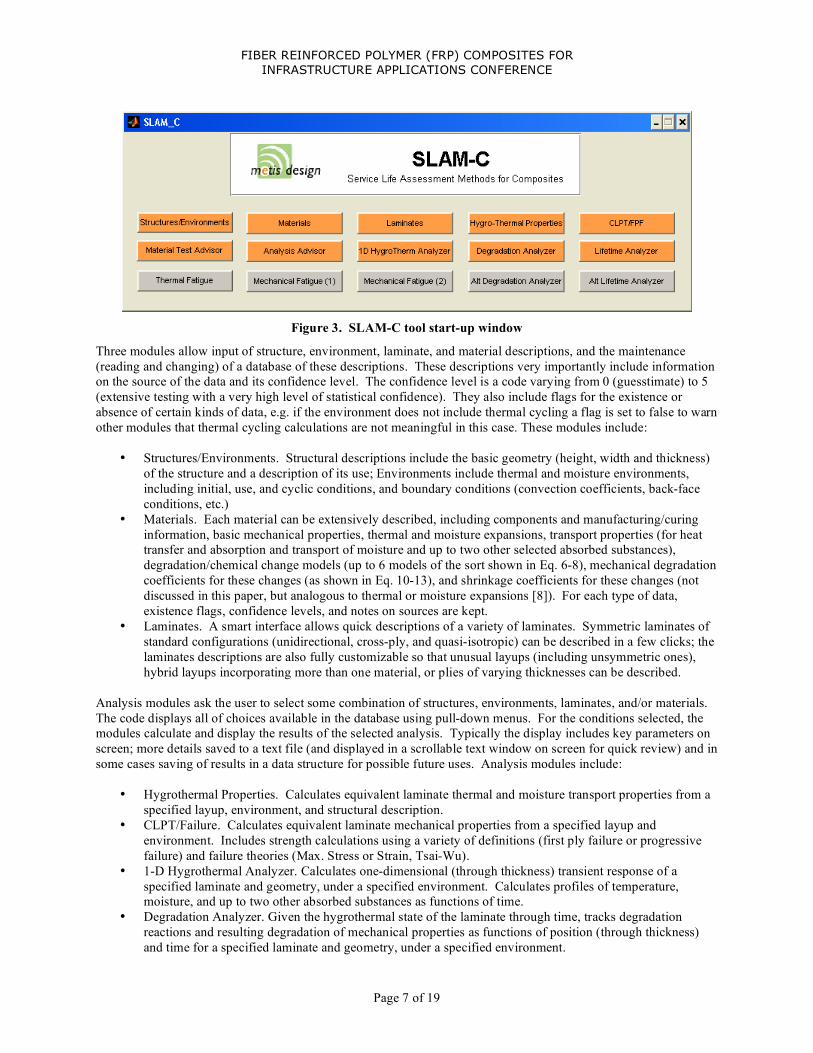
Figure 3. SLAM-C tool start-up window
Three modules allow input of structure, environment, laminate, and material descriptions, and the maintenance (reading and changing) of a database of these descriptions. These descriptions very importantly include information on the source of the data and its confidence level. The confidence level is a code varying from 0 (guesstimate) to 5 (extensive testing with a very high level of statistical confidence). They also include flags for the existence or absence of certain kinds of data, e.g. if the environment does not include thermal cycling a flag is set to false to warn other modules that thermal cycling calculations are not meaningful in this case. These modules include:
• Structures/Environments. Structural descriptions include the basic geometry (height, width and thickness) of the structure and a description of its use; Environments include thermal and moisture environments, including initial, use, and cyclic conditions, and boundary conditions (convection coefficients, back-face conditions, etc.)
• Materials. Each material can be extensively described, including components and manufacturing/curing information, basic mechanical properties, thermal and moisture expansions, transport properties (for heat transfer and absorption and transport of moisture and up to two other selected absorbed substances), degradation/chemical change models (up to 6 models of the sort shown in Eq. 6-8), mechanical degradation coefficients for these changes (as shown in Eq. 10-13), and shrinkage coefficients for these changes (not discussed in this paper, but analogous to thermal or moisture expansions [8]). For each type of data, existence flags, confidence levels, and notes on sources are kept.
• Laminates. A smart interface allows quick descriptions of a variety of laminates. Symmetric laminates of standard configurations (unidirectional, cross-ply, and quasi-isotropic) can be described in a few clicks; the laminates descriptions are also fully customizable so that unusual layups (including unsymmetric ones), hybrid layups incorporating more than one material, or plies of varying thicknesses can be described.
Analysis modules ask the user to select some combination of structures, environments, laminates, and/or materials. The code displays all of choices available in the database using pull-down menus. For the conditions selected, the modules calculate and display the results of the selected analysis. Typically the display includes key parameters on screen; more details saved to a text file (and displayed in a scrollable text window on screen for quick review) and in some cases saving of results in a data structure for possible future uses. Analysis modules include:
• Hygrothermal Properties. Calculates equivalent laminate thermal and moisture transport properties from a specified layup, environment, and structural description.
• CLPT/Failure. Calculates equivalent laminate mechanical properties from a specified layup and environment. Includes strength calculations using a variety of definitions (first ply failure or progressive failure) and failure theories (Max. Stress or Strain, Tsai-Wu).
• 1-D Hygrothermal Analyzer. Calculates one-dimensional (through thickness) transient response of a specified laminate and geometry, under a specified environment. Calculates profiles of temperature, moisture, and up to two other absorbed substances as functions of time.
• Degradation Analyzer. Given the hygrothermal state of the laminate through time, tracks degradation reactions and resulting degradation of mechanical properties as functions of position (through thickness) and time for a specified laminate and geometry, under a specified environment.

FIBER REINFORCED POLYMER (FRP) COMPOSITES FOR INFRASTRUCTURE APPLICATIONS CONFERENCE
Page 8 of 19
• Lifetime Analyzer. Uses information from the Degradation Analyzer and the CLPT/Failure module to predict the time at which the laminate will no longer be able to support a specified load set.
Finally, advisor modules are simple expert-system advisors that analyze material properties, structural geometries and environmental conditions, and return advice what analyses need to be conducted. For example, although most exposed civil structures tend to remain close to the environmental temperature, thick structures under rapidly changing temperature conditions may require transient or cyclic thermal analyses. Moisture transport is a slower phenomenon, and for most (but not all) structures (and, it turns out, test specimens) transient moisture absorption analyses are needed to correctly predict material state over moderate time scales (months). Current modules include:
• Analysis Advisor. Using the non-dimensional parameters in Eqs. 14-20, and the user-supplied descriptions of laminate, structure, and environment, advises if thermal or moisture transient analyses are needed, and if so if simple one-dimensional calculations of these phenomena are adequate.
• Materials Test Advisor. For a given material, structural application, and environment, audits the material database. Also requests the user specify a desired degree of confidence based on the needs of the analysis (i.e. exploratory design vs. final detailed design). Checks the material data base for the existence of all required data, and compares existing data confidence level to user needs. An extensive report is created, identifying missing data, highlighting areas of concern (inadequate confidence), and suggesting tests to complete the database to the necessary level of confidence.
The modular structure allows for the easy incorporation of additional modules. Short term plans including the inclusion of modules to consider thermal cycling [12], mechanical fatigue [e.g. 13], and creep rupture; modules could also be implemented to calculate alternate degradation theories as both a research tool and to present the analyst with alternatives.
Model-Based Test Plan The model described above requires a large number of material parameters to be accurately measured. This requires a carefully planned test program to provide the necessary data while keeping costs reasonable. A test plan was developed for this program using this logic. Mechanical properties were derived from standard mechanical tests on unidirectional coupons: ASTM (American Society for Testing and Materials) Standard D 3039. Shear properties were derived from [+/-45] angle ply “Rosen” coupons following ASTM D 3518. Thermal and moisture expansion properties, and thermal transport properties were not anticipated to be important, so properties available in the literature for similar materials were used. Moisture absorption properties were measured as part of companion effort [1]. The degradation model parameters were collected primarily by the use of low cost short beam shear (SBS) test according to ASTM D 2344. Specimens were treated under a variety of conditions, and the SBS strength (at room temperature) measured after treatment. The conditions were designed to at least partly decouple the many terms in Eq. 13 (which governs SBS strength). Based on prior experience and the relatively low temperatures being considered, the thermal degradation mechanism is not expected to be activated at any meaningful rate. Thus the constants kb, nb, Eb, and ΔPb will be rather arbitrarily assigned values derived from previous work involving much higher temperatures [11]. The “post cure” (a) mechanism will be explored by aging specimens in both hot dry and room temperature (RT) dry conditions. The strength increase ΔPa(MS) can be directly observed from the post-cure of hot dry specimens, which are expected to fully postcure quickly. Rate information (constants in Eq. 6) can be determined from fits to the strength increases over time seen at the two conditions. Most of the test matrix concentrates on getting good data for the moisture-induced degradation (c) mechanism, Eq. 8. RT wet results over short times should give the strength reduction due solely to moisture (ΔPm(MS)) directly. The
FIBER REINFORCED POLYMER (FRP) COMPOSITES FOR INFRASTRUCTURE APPLICATIONS CONFERENCE
Page 9 of 19
strength reduction due to moisture-induced degradation (ΔPc(MS)) and its rate and temperature dependence (kc, nc and Ec) will then be determined by the results of the hot-wet and warm-wet tests through a fitting process. Note that the results of the above data reduction will strictly apply only to SBS tests. To relate the SBS results to laminate properties, treated unidirectional tensile and Rosen shear coupons will be tested at wider intervals. This data will be reduced to ΔPa, ΔPc and ΔPm parameters for lamina tensile and shear properties; the rate constants will be assumed to be the same. A quasi-isotropic laminate will then be used as a check to see if CLPT calculations using the reduced properties can predict the behavior of a degraded non-trivial laminate.
Test Program The objectives of the testing phase of the study were to manufacture a variety of specimens, condition them by exposing them to various temperature and moisture environments, and test them for strength and stiffness after specific time periods of exposure in these environments. An overarching objective was to conduct the testing phase for a reasonable cost, but produce good quality specimens and test data. The specimens to be conditioned were cut from glass-epoxy panels manufactured using the VARTM infusion process. Hexcel unidirectional E-glass cloth (95% in fiber direction, 5% perpendicular to fiber direction), 6 oz per square yard, from Fiberglassite [14] and SC-780 toughened epoxy resin, specifically designed for the VARTM process, from Applied Poleramic, Inc. [15] constituted the material system. Resin infusion was accomplished under full vacuum, which was reduced to 34 kPa (5 psi) after full wetting of the dry glass. The panels remained under the reduced vacuum for 24 hours, after which they were removed from the vacuum bag. No post cure was used, rather the specimens remained in an 18 deg. C (65 deg. F) room temperature environment until they were cut into smaller specimens. Panels with lay-ups of [0]8 and [0]40 unidirectional, [±45/0/90]s quasi-isotropic, and ±45 (Rosen) fiber orientations were fabricated. Only one thicker unidirectional 76 cm (30 in.) by 56 cm (22 in.) panel was made, while two 56 cm by 56 cm (22 in. by 22 in.) panels each of the thinner layups were made. The thicker unidirectional panel was to be cut into short beam shear specimens, while the other panels were for tensile specimens. For each environmental condition and exposure time there were be three specimens for the tensile tests and five specimens for short beam shear tests. The dimensions of the SBS specimens were 4.44 cm (1.75 in.) long (fiber direction) by 1.27 cm (0.5 in.) wide by approximately 0.64 cm (0.25 in., 40 layers) thick. To avoid unwanted effects of moisture absorption through cut edges, the SBS specimens were conditioned as 4.44 (1.75 in.) (fiber direction) by 12.7cm (5 in.) so-called uber specimens. Just before testing, these uber specimens would have five SBS specimens cut from their central region, and these would be loaded in three-point bending in the 4.44 cm (1.75 in.) direction. The 40-layer panel was thus cut into 21 uber short beam shear specimens. Each thinner panel was cut into 17 35.6 cm (14 in.) long by 2.54 cm (1 in.) wide tensile specimens, the length being selected so there was 5.1 cm (2 in.) of specimen to grip on each end, leaving a 25.4 cm (10 in.) test section. The uber short beam shear specimens and tensile specimens were cut from the larger panels using a water-cooled diamond blade circular saw. Specimens were cut 5.1 cm (2 in.) from the edges of the panels so as to not involve any irregularities in the specimens. After cutting and labeling, the specimens were weighed, and the width and thickness of each specimen was measured at three locations along the specimen length. Five environmental exposure conditions were used: Dry room temperature conditions, immersion in room temperature water, immersion in 43.3 C (110 deg. F) water, immersion in 65.6 C (150 deg. F) water, and in an oven exposed to 65.6 C (150 deg. F) room air. Four approximately equally spaced exposure times were selected, so-called times t1, t2, t3, and t4, the longest being about six months. These times were in addition to no exposure time, time t0, which occurred at the start of the six-month period. Only short beam shear specimens were to be tested at all five times, (four of which have occurred – t4 has not occurred as of this writing), while the tensile testing was conducted at t0, t2, and will be conducted at t4. The 90 deg. specimens were only tested at time t0 and were not conditioned. For water immersion 15 qt. (14 L) plastic containers with snap-on lids (www.sterilite.com) were used. The water in two of these containers was heated using submersible aquarium heaters, specifically model VTX-300 Visi-Therm heaters (www.marineland.com) with a 300W capacity. The heaters were prevented from direct contact with the

FIBER REINFORCED POLYMER (FRP) COMPOSITES FOR INFRASTRUCTURE APPLICATIONS CONFERENCE
Page 10 of 19
plastic containers by way of steel racks on the bottoms of the containers. In each heated container, to prevent the composite specimens from directly contacting the heater, another rack was used above the heater and the specimens were placed on this rack. As the temperatures in two of these containers was to be controlled, TJ36-CASS-18U-12-SMPW-M thermocouple assemblies from Omega Engineering, Inc (www.omega.com) were used to monitor the temperatures and Omega Engineering, Inc. CSI32K digital benchtop controllers, model T-CSI32, were used to control the temperatures. As the heaters were originally intended to be used in aquariums, they had cut-off switches that prevented their use above temperatures comfortable for aquatic life. These were disabled. The set-up for room temperature water immersion was identical, except there were no heaters. For the two elevated temperature immersion conditions, to minimize the energy required to maintain the desired temperature, the plastic containers were insulated on the bottom, the four sides, and the top with closed-cell 2.5 cm (1 in.) thick foam. Distilled water was used in all baths. Exposure to 65.6 C (150 deg. F) room air was provided by a 1000 W Blue M model OV-472A-2 oven (www.blue-m.com). The temperature of the oven was monitored with an Enviro-Safe glass thermometer (http://www.hbinstrument.com/) inserted through an opening in the top of the oven that was designed for this purpose. Dry room temperature conditions for specimens were achieved by storing the specimens at room temperature in a sealed desiccator kept dry with Drierite granules (www.drierite.com). To randomize which three quasi-isotropic specimens would be exposed to which conditions, the program Mathematica was used to develop a pseudo-random selection of which particular specimen would be exposed to which particular environment for what particular period of time. When a set of specimens were ready for testing, they were removed from immersion containers, the oven, and the desiccator. The specimens immersed in water were covered with a brown film that perhaps was a material that had leached out of the specimens. As a result, these specimens were cleaned and the surfaces allowed to dry. Then, all specimens were weighed. The five short beam shear specimens were cut from each uber specimen as shown in Figure 4. The short beam shear specimens were tested in a home-built three-point bending fixture shown in Figure 5.
Figure 4. Short beam shear specimens cut from uber specimens S-7, S-12, S-15, and S20.

FIBER REINFORCED POLYMER (FRP) COMPOSITES FOR INFRASTRUCTURE APPLICATIONS CONFERENCE
Page 11 of 19
Figure 5. Three-point bend short beam shear test fixture with specimen in place
The three-point bend fixture was mounted in an Instron load frame (www.instron.com) and the displacement of the load frame cross head and the applied load were measured. These data were recorded automatically with a computer-based data acquisition system, the data being recorded twice per second. The cross-head rate was 1 mm/sec. Tensile testing was done in the same Instron load frame using mechanical wedge action grips with serrated grip faces. As the tensile specimen surfaces resulting from the VARTM process were also somewhat serrated but smooth, due to the texture of the release plys and resin distribution medium, the grips could sometimes slip when the tensile load was increased. To overcome this problem, type 304 stainless steel wire cloth, 100 by 100 mesh with 0.114 mm (0.0045 in.) wire diameter (www.mcmaster.com), was used between the grip surfaces and the surfaces of the tensile specimens. The extension of the specimens was measured with an Instron extensometer and the load, cross head motion, and extensometer measurement was recorded via computer twice per second as the cross head moved at a rate of 1 mm/sec.
Test Results (to date) Preliminary results from the study are provided in Tables I and II. The results for the tensile testing of the eight-layer 0 deg. unidirectional (U), 90 deg. (N), quasi-isotropic (Q), and ±45 (R) specimens are in Table I, while short beam shear strength data are in Table II. On the tables, S is the tensile failure stress, E the tensile modulus, and ILSS stands for Interlaminar Shear Strength. The exposure identification is as follows:
• Room temperature dry in desiccators: no M/no T (M for moisture, T for temperature) • Immersion in room temperature water: M/no T • Exposure to 65.6 C (150 deg. F) room air: no M/T • Immersion in 43.3 C (110 deg. F) water: M/T/2 • Immersion in 65.6 C (150 deg. F) water: M/T

FIBER REINFORCED POLYMER (FRP) COMPOSITES FOR INFRASTRUCTURE APPLICATIONS CONFERENCE
Page 12 of 19
Table I. Results from testing tensile specimens (average of 3 specimens)
!
" # $ # $ # $ $
%&' (&' %&' (&' %&' (&' (&'
)*+"*",'-. /0121 132* 4025 6021 0712* 672* 662/
)0+"40",'-.
89"%:89"; /4127 562/ 0//20 0*21 632/
"
%:89"; 3<*2< 5*27 06/2/ 6727 6021
89"%:; //026 5421 0/72/ 0*20 602/
"
%:;:0 17723 1127 63020 6421 72/
%:; 13723 5523 6152< 6<25 <24
= > ?
Table II. Results from testing short beam shear specimens (average of 5 specimens)
!"#$%!"#& $%!"#& !"#$%& $%&%' $%&
()*#)#+,-.
/011*#$2,
(3*#'4#+,-.
/011*#$2,
('*#5'#+,-.
/011*#$2,
(6*#337#+,-.
/011*#$2,'895 ':93
'49:659:;59';)94;696
:79;
;69; ;496
:596 ;'96
1<1
:798
;)98 ;393 6:94
The SBS results are shown normalized (so the initial strength is 1) in Figure 6. The post-curing of the hot dry specimens (strength goes up) is clear, as is the temperature and time dependent degradation of the wet specimens.
Figure 6. Summary of results of SBS testing to date

FIBER REINFORCED POLYMER (FRP) COMPOSITES FOR INFRASTRUCTURE APPLICATIONS CONFERENCE
Page 13 of 19
Example use of Tools In this section, the SLAM-C tool set will be used to define the environments, geometries and laminates used in the test program. The data collected will be entered into the material database, and then refined iteratively by using the tool itself to make predictions of the tests, and correcting the database as necessary. Finally, the calibrated tools will be used to make some successful predictions about material behavior in different laminates, and under different environments. The analysis advisor feature of the code provides hints, and analysis results confirm, that in the time span considered, moisture absorption effects are confounded with degradation mechanisms, complicating interpretation of the accelerated test results. Structures and Environments The first tool on the SLAM-C starting interface (Fig. 2) allows the definition of geometries. The geometries in Table III were entered into a database. The tool records intended uses and levels of confidence; the test specimens are produced under controlled laboratory conditions and hence are high confidence, but the “structure patch” is a guesstimate.
Table III. Structural definitions entered into tool
Structure Patch
Tensile test
“Uber” SBS coupon
SBS test specimen
Typical intended
use
Specimen conditioned after
cutting
Panel of specimens
conditioned uncut
Specimen conditioned after
cutting Length (m)
5
0.3556 (14”)
0.0635 (2.5”)
0.0508 (2”)
Width (m)
1
0.0254 (1”)
0.1778 (7”)
0.0127 (1/2”)
Thickness (mm) 0* 0 0 0
* 0 thickness directs tool to use thickness of specified layup
The environments created corresponded to the Virginia Tech and Army ERDC accelerated conditioning environments. In every case, thermal and moisture transient environments were defined. A period of interest of 15 days (the shortest conditioning time considered) was entered in all cases. The confidence level was high except for the “swamp” nominal use case. All environments were defined as starting at 20 C (RT) and 0% moisture.
Table IV. Environment definitions entered into tool
RT RT Wet RT Dry Hot Dry Hot Wet Warm Wet
Hot Damp Very Hot Swamp
VT, use VT VT VT VT VT ERDC ERDC use
Tfinal (C) 20 20 20 66 66 43 85 150 40
Mfinal 50 100 0 0 100 100 50 0 80
Back exposed exposed exposed exposed exposed exposed exposed exposed insulated
hc 10* 100 10 10 100 100 10 10 10 * hc approximate – 10 W/m2C typical of vapor, 100+ of liquid
Materials The material definition tool’s input panel is shown in Figure 7. This is actually the first of two such panels, which emphasizes the large number of material parameters needed for a complete durability analysis under varying temperature and moisture conditions. A complete set of material properties was assembled for the Glass-Epoxy composite material used in the study. The sources of data are discussed in the Model-Based Test Plan section above; some (although not all) of the data entered were derived from the tests presented in the previous section. The tool recorded the origin of each type of data, and its confidence level, which varied from 3 for the best and most consistent data to 1 (or even 0) for a few properties (e.g. thermal expansion) taken by analogy from similar but not identical materials. Note the data in Fig. 7 is not accurate, and the material properties are not tabulated here, as at the time of this writing the data was still being collected and reduced. At the conclusion of this program a complete

FIBER REINFORCED POLYMER (FRP) COMPOSITES FOR INFRASTRUCTURE APPLICATIONS CONFERENCE
Page 14 of 19
data set will be published. As a check, the Materials Advisor tool was used to check and summarize the entered data, and document the data and its confidence level.
Figure 7. Example material input - first of two windows
Laminates The laminate input tool was used to define a set of laminates of interest, shown in Table V. Note the SBS specimens actually had 40 (thin) plies, but for computational simplicity they were modeled as 8 thicker equivalent plies. This had no consequences for the analyses done in this session. The fact that artificially thick equivalent plies were used was recorded as a note in the database, which should prevent future confusion.
Table V. Laminate definitions entered into tool
Uni SBS Uni Tensile Quasi-iso Tensile Quasi-iso Patch
Unidirectional Unidirectional Quasi-isotropic
[0/90/+-45]s Quasi-isotropic
[0/90/+-45]s
Ply thickness 0.8 mm (artificial) 0.2 mm 0.2 mm 0.3 mm
Number of plies 8 8 8 8
Total Thickness 6.4 mm (1/4”) 1.6 mm 1.6mm 2.4 mm
(0.1”) Material Glass/Epoxy Glass/Epoxy Glass/Epoxy Glass/Epoxy
Hygrothermal and Mechanical properties Two tools calculate equivalent laminate mechanical, thermal, and moisture diffusion properties. These calculations were checked against legacy codes and found to agree. An independent check was carried out by predicting the failure stress of the unconditioned quasi-isotropic laminates based on material properties derived from the unidirectional and Rosen specimens. It was found (Fig. 8) that a progressive failure criteria correctly predicted the failure stress of the quasi-isotropic laminates. Interestingly, two different first-ply failure criteria both drastically under-predicted the strength. Similar agreement was achieved when predicting the strength of conditioned quasi-isotropic specimens at t2 using predicted degraded material properties.

FIBER REINFORCED POLYMER (FRP) COMPOSITES FOR INFRASTRUCTURE APPLICATIONS CONFERENCE
Page 15 of 19
Figure 8. Prediction of unconditioned Quasi-isotropic laminate failure
Material and Analysis Advisors The material advisor was used to audit the material database as it was being constructed. It summarizes the data in a report, warms of missing data or low data quality, and provides recommendations for further testing. As the material database is still evolving, these results will not be presented here, although they were found to be very useful during the progress of the work. The user picks (from the entered library) a set of geometry, environment, and laminate. The analysis advisor then uses the dimensionless parameters of Eqs. 14-20, along with information in the databases, to advise the user if transient thermal or moisture calculation need to done, and if so whether they can be one-dimensional, or need to be two- or three-dimensional. A text report is created summarizing the results, which are also displayed on screen. All of the environments structures, and laminates of interest were analyzed, in all relevant combinations. It was found that in all cases, the laminates reach temperature equilibrium with the environment in minutes, so no thermal transient analyses are needed for these condition. Moisture, on the other hand was found to reach equilibrium in the time-span of interest (15 days) in only the thinnest specimens in the hottest environments. Thin specimens at lower temperatures will not saturate completely in 15 days. The thick specimens will generally take much longer than 15 days to become moisture saturated. The results of the advisor runs are summarized in Table VI. In table VI, “Trans” means transient moisture analysis is need to understand the material condition at 15 days into the conditioning; “(Trans)” means the effect is modest (the material is within 15% of saturation); “Severe lag” indicates that the specimens are only starting the moisture absorption process (10% saturation or less); and “2-D” indicates that a 2-dimensional analysis will be required as moisture ingress from the specimen edges is significant.
Table VI. Analysis Advisor Results
geometry
thickness
RT 23C
Warm 43C
Hot 66C
v. Hot 85C
Patch 2.4 mm, insulated Trans Trans (Trans) (Trans)
Tensile specimen 1.6 mm Trans (Trans) (Trans) -
Uber SBS panel 6.4 mm Severe lag Trans Trans Trans
SBS specimen
6.4 mm x 12.7 mm wide
Severe lag, 2-D Trans, 2-D Trans, 2-D Trans, 2-D

FIBER REINFORCED POLYMER (FRP) COMPOSITES FOR INFRASTRUCTURE APPLICATIONS CONFERENCE
Page 16 of 19
1-D hygrothermal analyzer The analysis advisor indicated that thermal analyses were unnecessary so they will not be presented here (although this advice was successfully confirmed using the analyzer!). Per the advisor, the moisture content as a function of time was calculated for all types of specimens. Typical results are shown in Fig. 10, which shows the moisture distribution through the thickness of an SBS uber panel in hot wet conditions. The moisture state is evolving towards saturation during the times when the first two sets of tests were performed. For example, the center of the specimen (x=0) is only about half way to saturation when the first set of tests were done (t1 = 27 days). This confounds the interpretation of these results, complicating the data reduction process.
Figure 10. Moisture absorption analysis of thick specimen under hot-wet conditions
Degradation analyzer The degradation analyzer was first used to check and improve the reduced degradation data collected from the test program. For example, hot and room-temperature dry conditioning evoked the post-cure reaction in the SBS specimens, which was fit to this data, as shown in Fig. 11.
Figure 11. Test data under hot dry and RT dry conditions, with model fit
Under wet conditions, the moisture absorption and hygro-thermal degradation mechanisms are confounded, making the fitting process more difficult. It was found that the post-cure mechanism can also confound these results (see the initial rise in properties in Fig. 12). However, the existence of moisture diffusivity data and the transient analysis capability (above) help by making the moisture distributions known quantities during data reduction. The post-cure mechanism is also predictable based on the data above. The remaining unknowns are the hygro-thermal degradation constants, which are fit to the data. The resulting fit for the SBS specimens, as of this writing, is shown in Fig. 12.

FIBER REINFORCED POLYMER (FRP) COMPOSITES FOR INFRASTRUCTURE APPLICATIONS CONFERENCE
Page 17 of 19
Figure 12. Test data under wet conditions, cold, warm and hot, with model fit
The unidirectional and Rosen (+/-45) specimen data was used to get an understanding the fiber direction and stiffness failure coefficients (eqs. 10-14). As of this writing, only one set of data is available for each of these specimen types (conditioned to t2) so the fit it easy but of low confidence. Note that Figs. 11 and 12 do not include the t3 data shown in Fig. 6, as this data only became available in the last few days before this paper was written. The bottom line is that at least for the early (t2) data, a good fit to all data can be achieved with the model. Predictive analysis The calibrated models were used to predict the degraded strength of the quasi-isotropic laminate (successfully) and also to predict the degradation of a set of specimens being conditioned at another laboratory [1]. These specimens were conditioned in an environment outside the range of environments considered in the test VT program (85C, 50% RH), so the model has to extrapolate somewhat to predict their behavior. These results will be reviewed in full in the companion paper from that laboratory. Figure 13 is included to illustrate success.
Figure 13. Prediction of behavior of SBS specimens conditioned in very hot, damp conditions

FIBER REINFORCED POLYMER (FRP) COMPOSITES FOR INFRASTRUCTURE APPLICATIONS CONFERENCE
Page 18 of 19
Discussions and Conclusions The work succeeded in creating, from modest extensions of current knowledge, a relatively simple but adequately accurate model, which can be calibrated with a non-trivial but tractable and affordable set of standard tests. This model was implemented in a user-friendly tool set to make it accessible to composite engineers. Tool set innovations include the maintenance of extensive databases of environments, geometries, laminates, and material properties, along with important information on the origins and confidence levels of all this data, and the use of simple expert system advisors to help engineers understand what analyses and tests are needed to achieve results at the desired level of confidence. During the course of this work, some lessons emerged or were reinforced. To summarize:
• Even simple degradation models require an extensive database of material properties. Understanding the accuracy and pedigree of this data is very important to achieve high-confidence results.
• Over typical timescales for accelerated testing, moisture absorption and degradation mechanisms are both ongoing. These effects are strongly dependent on both environments and specimen geometries. This complicates the interpretation and reduction of test data, and if not understood may result in erroneous conclusions. The analysis advisor and simple hygro-thermal analyzer features of the SLAM-C tool are very useful for managing this issue.
• Over the relatively short timescale studied (67 days) the method resulted in a calibrated model that appeared to have predictive power over conditions even somewhat outside of the range used in the calibrating test (i.e. could be extrapolated to some degree in environment). The models also predicted more complex laminate behavior based on simple tests.
• Unfortunately, due primarily to the fact that the moisture and degradation effects were confounded in this period, it is difficult to say whether the calibrated model will successfully predict longer term behavior (over years). Planned tests at longer time periods (by which time the moisture in most specimens will have reached equilibrium) should shed light on this issue.
Overall, the method seems very useful and promising, and has been demonstrated to be capable of capturing and predicting material behavior over the period studied. Further data (to be collected under this program) is needed to determine if the model can predict truly long-term behavior. The flexible nature of the tool developed should make any required adjustments to the model easy to implement. Other degradation mechanisms, such as thermal and mechanical cycling, should be straightforward to implement as well.
Acknowledgement This work was sponsored by ERDC contract W9132T-09-C-0006 “Service Life Assessment Methodology for Composites (SLAM-C) Extended Study” under the supervision of Jonathan Trovillion.
References and Notes 1. Trovillion, Jonathan, “Hygrothermal Degradation of Composites in Accelerated Testing,” Fiber Reinforced
Polymer (FRP) Composites for Infrastructure Applications Conference, San Francisco, CA, November 2009. 2. McManus, H. L., and Springer, G. S., "High Temperature Thermomechanical Behavior of Carbon-Phenolic and
Carbon-Carbon Composites, I. Analysis," Journal of Composite Materials, Vol. 26, No. 2, 1992, pp. 206-229. 3. Kreith, Frank, and Bohn, Mark, Principles of Heat Transfer, Fourth Edition, Harper and Row, 1986, pp. 101-
107. 4. Tsai, Stephen W., Composite Design, 4th Edition, Think Composites, 1988, Section 16. 5. Foch, B. J., “Integrated Degradation Models for Polymer Matrix Composites”, Master of Science Thesis,
Massachusetts Institute of Technology, May 1997. 6. Cunningham, R. A. 1997. “High Temperature Degradation Mechanisms in Polymer Matrix Composites,” S.M.
Thesis, Massachusetts Institute of Technology, Cambridge, MA. 7. C.C. Chamis. “Simplified Composite Micromechanics Equations For Hygral, Thermal, And Mechanical-
Properties.” SAMPE Quarterly-Society For The Advancement Of Material And Process Engineering, 15 (3): 14-23, 1984.

FIBER REINFORCED POLYMER (FRP) COMPOSITES FOR INFRASTRUCTURE APPLICATIONS CONFERENCE
Page 19 of 19
8. McManus, H. L. and C. C. Chamis. “Stress and Damage in Polymer Matrix Composite Materials Due to
Material Degradation at High Temperatures,” NASA Technical Memorandum 4682, 1996. 9. Tsai, Stephen W., Composite Design, 4th Edition, Think Composites, 1988, Section 12. 10. Crews, L. K., and McManus, H. L., "Modeling the High-Temperature Degradation of Graphite/Epoxy,"
Proceedings of the American Society for Composites 12th Technical Conference on Composite Materials, Detroit MI, Oct. 1997, pp. 1123-1132.
11. Seth S. Kessler, Hugh L. McManus and Michael W. Hyer, “Service Life Assessment Methodology for Composites,” Proceedings of the 22nd Annual Technical Conference of the American Society for Composites, Seattle Washington, Sept 17-19 2007, Paper ASC-2007 #020.
12. McManus, H. L. and Maddocks, J. R., "On Microcracking in Composite Laminates under Thermal and Mechanical Loading," Polymers and Polymer Composites, Vol. 4, No. 5, 1996, pp. 304-314.
13. Nathan Post, John Bausano, Scott W. Case and John J. Lesko, “Modeling the Remaining Strength of Structural Composite Materials Subjected to Fatigue,” International Journal of Fatigue, 28, 1100-1108, October 2006.
14. http://www.fiberglasssite.com/servlet/the-17/FIBERGLASS-CLOTH-6-oz/Detail 15. http://www.appliedpoleramic.com/