Embed Size (px)
Citation preview
SLINGSBY Advanced Composites Ltd
Service Bulletin S.B. No: 187
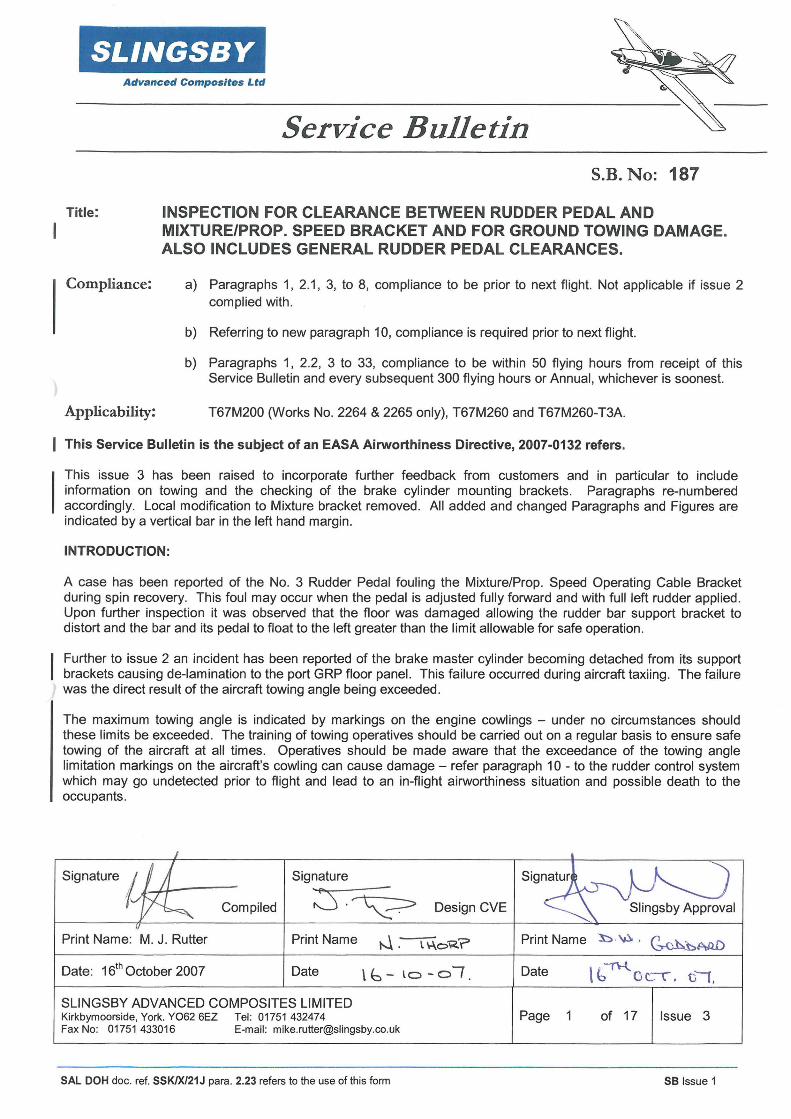
Title: INSPECTION FOR CLEARANCE BETWEEN RUDDER PEDAL AND MIXTURE/PROP. SPEED BRACKET AND FOR GROUND TOWING DAMAGE. ALSO INCLUDES GENERAL RUDDER PEDAL CLEARANCES.
Compliance: a) Paragraphs 1, 2.1, 3, to 8, compliance to be prior to next flight. Not applicable if issue 2 complied with.
b) Referring to new paragraph 10, compliance is required prior to next flight.
b) Paragraphs 1, 2.2, 3 to 33, compliance to be within 50 flying hours from receipt of this Service Bulletin and every subsequent 300 flying hours or Annual, whichever is soonest.
Applicability: T67M200 (Works No. 2264 & 2265 only), T67M260 and T67M260-T3A.
This Service Bulletin is the subject of an EASA Airworthiness Directive, 2007-0132 refers.
This issue 3 has been raised to incorporate further feedback from customers and in particular to include information on towing and the checking of the brake cylinder mounting brackets. Paragraphs re-numbered accordingly. Local modification to Mixture bracket removed. All added and changed Paragraphs and Figures are indicated by a vertical bar in the left hand margin.
INTRODUCTION:
A case has been reported of the No. 3 Rudder Pedal fouling the Mixture/Prop. Speed Operating Cable Bracket during spin recovery. This foul may occur when the pedal is adjusted fully forward and with full left rudder applied. Upon further inspection it was observed that the floor was damaged allowing the rudder bar support bracket to distort and the bar and its pedal to float to the left greater than the limit allowable for safe operation.
Further to issue 2 an incident has been reported of the brake master cylinder becoming detached from its support brackets causing de-lamination to the port GRP floor panel. This failure occurred during aircraft taxiing. The failure was the direct result of the aircraft towing angle being exceeded.
The maximum towing angle is indicated by markings on the engine cowlings - under no circumstances should these limits be exceeded . The training of towing operatives should be carried out on a regular basis to ensure safe towing of the aircraft at all times. Operatives should be made aware that the exceedance of the towing angle limitation markings on the aircraft's cowling can cause damage - refer paragraph 10 - to the rudder control system which may go undetected prior to flight and lead to an in-flight airworthiness situation and possible death to the occupants.
Signature
Compiled :::S ·~ Design CVE
Print Name: M. J. Rutter Print Name t--1 -~o"R.? Print Name l:::> . ~ • ~.hM.D
Date: 161h October 2007 Date \ b - lo - o I . Date \ '1\-l ~ Ot..'l. til,
SLINGSBY ADVANCED COMPOSITES LIMITED Kirkbymoorside, York. Y062 6EZ Tel: 01751 432474 Page 1 of 17 Issue 3 Fax No: 01751 433016 E-mail: [email protected]
SAL DOH doc. ref. SSK/X/21J para. 2.23 refers to the use of this form SB Issue 1

SLINGSBY S.B. No: 187 Issue: 3 Page 2 of 17
Advanced Composites Ltd
The use of non Slingsby type vehicle or hand tow-bars or trolley/cart, (i.e. that cradle the nosewheel), are PROHIBITED for use on the Slingsby T67 type aircraft.
Therefore only Slingsby tow-bars SHALL be used for towing, i.e. T67A-88-201 for vehicle towing and T67B-88-203 (adjustable handle length) or T67B-88-207 (fixed handle length) for hand towing.
Vehicles when used for towing with the Slingsby vehicle type tow-bar SHALL ensure that the driver has a clear view of the tow-bar turn limitation markings on the aircrafts cowling. Additionally ensure whilst towing with a vehicle that an operative occupies the cockpit ready to apply brakes in an emergency.
This Service Bulletin is issued to address the incidents related to above and to reinforce the importance of ensuring correct clearances, towing instructions and maintenance of the rudder operating mechanism, mountings and stops to ensure the required clearances for safe operation.
This Service Bulletin addresses issues raised in previous Service Bulletins, see below, and draws notice to the relevant Maintenance Manual requirements . The information contained within th is Service Bulletin supersedes the Service Bulletins listed below and Maintenance Manual instruction regarding clearances where applicable.
SB 049 Rudder Mechanism to Fuel Pipe Clearance Check.
SB 051 Inspection of Rudder Cable to Link Plate Socket Head Cap Screw.
SB 071 Inspection of Rudder Pedal Lay shaft Mounting Brackets.
SB 075 Inspection of Rudder Pedal Slider/Heater Distribution Box Clearance.
SB 083 Inspection for Foul Between no.2 Rudder Pedal Pad Pivot and Nose wheel Steering Rod Arm.
SB 088 Rudder Pedal to Mixture Lever Potential Foul.
SB 168 Inspection of Cockpit Floor Beneath Port Rudder Bar Support Bracket.
ACTION:
Prior to starting the inspections it is recommended that this Service Bulletin is read in its entirety and understood. Ensure that notes are made of the positions of removed items to aid correct reassembly, unless otherwise specified by this Service Bulletin. If in doubt, contact Slingsby Advanced Composites Ltd, (SACL).
1. With Right Hand pilots left pedal (Pedal No. 3) adjusted fully forward, with left rudder applied, apply brake together with a left hand side force on the pedal. Check for clearance on mixture/propeller speed cable support bracket. Refer Figure 1.
2. Clearance should be a minimum of 3mm. Figure 1 refers.
2.1 If the clearance is less than 3mm, the following inspection and corrective actions, paragraphs 3 to 32, shall be carried out in order to increase the clearance up to the required minimum of 3mm.
2.2 If the clearance is 3mm or greater when first measured, the following inspections, paragraphs 3 to 32, must still be carried out to ensure the whole rudder pedal system is within required tolerances and free from defects.
3. Check forward, aft and lateral play in pedal pads and their sliders; ensure play is no greater than 4.8mm when pedals locked in any of the adjustment positions. If greater than 4.8mm then refurbish pedal assemblies, refer T67M260 Maintenance Manual Paragraph 5.6.5.1 (3). Consult SACL if required.
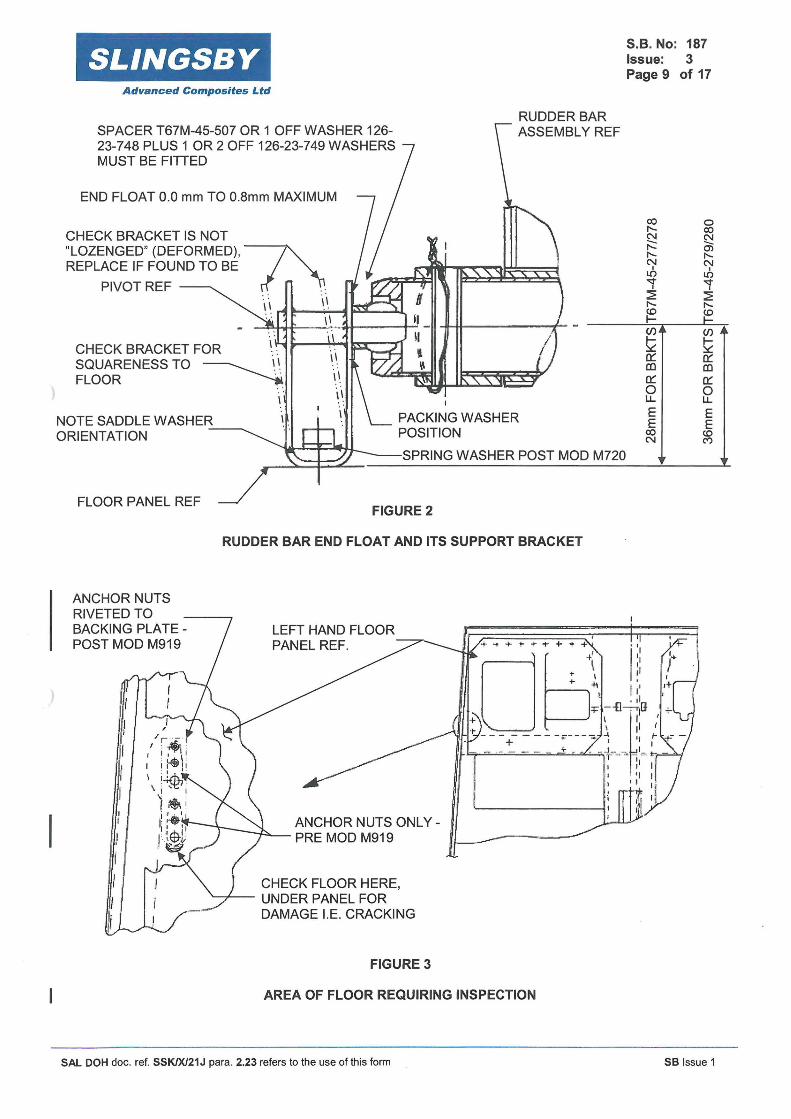
4. Check rudder pedal bar end float is no greater than 0.8mm. Acceptable end float is O.Omm to 0.8mm. If end float is greater than 0.8mm then rectify IAW paragraph 14. Refer Figure 2.
SAL DOH doc. ref. SSK/X/21J para. 2.23 refers to the use of this form SB Issue 1
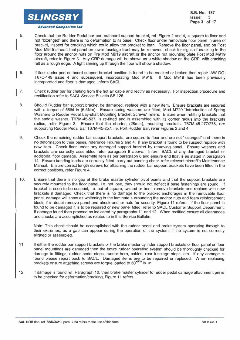
5.
I 6.
I 7.
8.
9.
10.
SLINGSBY Advanced Composites Ltd
S.B. No: 187 Issue: 3 Page 3 of 17
Check that the Rudder Pedal bar port outboard support bracket, ref. Figure 2 and 4, is square to floor and not "lozenged" and there is no deformation to its base. Check floor under removable floor panel in area of bracket, inspect for cracking which could allow the bracket to lean. Remove the floor panel, and on Post Mod M945 aircraft fuel panel on lower fuselage front may be removed, check for signs of cracking in the floor around the anchor nuts on Pre Mod M919 aircraft or the anchor nut mounting plate Post Mod M919 aircraft, refer to Figure 3. Any GRP damage will be shown as a white shadow on the GRP, with cracking felt as a rough edge. A light shining up through the floor will show a shadow.
If floor under port outboard support bracket position is found to be cracked or broken then repair IAW DOI T67C-149 issue 4 and subsequent, incorporating Mod M919. If Mod M919 has been previously incorporated and floor is damaged, inform SACL.
Check rudder bar for chafing from the hot air cable and rectify as necessary. For inspection procedure and rectification refer to SACL Service Bulletin SB 126.
Should Rudder bar support bracket be damaged, replace with a new item. Ensure brackets are secured with a torque of 581bf in (6.5Nm). Ensure spring washers are fitted; Mod M720 "Introduction of Spring Washers to Rudder Pedal Lay-shaft Mounting Bracket Screws" refers. Ensure when refitting brackets that the saddle washer, T67M-45-537, is re-fitted and is assembled with its corner radius into the brackets radius, refer Figure 2. Ensure that the shorter, (28mm), mounting brackets, T67M-45-277/278, are supporting Rudder Pedal Bar T67M-45-257, i.e. Port Rudder Bar, refer Figures 2 and 4.
Check the remaining rudder bar support brackets, are square to floor and are not "lozenged" and there is no deformation to their bases, reference Figures 2 and 4. If any bracket is found to be suspect replace with new item. Check floor under any damaged support bracket by removing panel. Ensure washers and brackets are correctly assembled refer paragraph 8 above. Inform SACL of any damaged bracket or additional floor damage. Assemble item as per paragraph 8 and ensure end float is as stated in paragraph 14. Ensure bonding leads are correctly fitted, carry out bonding check refer relevant aircraft's Maintenance Manual. Ensure correct length screws for attaching the rudder bar support brackets have been fitted in the correct positions, refer Figure 4.
Ensure that there is no gap at the brake master cylinder pivot points and that the support brackets are securely mounted to the floor panel, i.e. not lose, they should not deflect if base fastenings are sound. If bracket is seen to be suspect, i.e. out of square, twisted or bent, remove brackets and replace with new brackets if damaged. Check that there is no damage to the bracket anchorages in the removable floor panel, damage will show as whitening in the laminate surrounding the anchor nuts and foam reinforcement block, if in doubt remove panel and check anchor nuts for security. Figure 11 refers . If the floor panel is found to be damaged it is to be repaired or new panel fitted, refer to SACL Customer Support Department. If damage found then proceed as indicated by paragraphs 11 and 12. When rectified ensure all clearances and checks are accomplished as related to in this Service Bulletin.
Note: This check should be accomplished with the rudder pedal and brake system operating through to their extremes, as a gap can appear during the operation of the system, if the system is not correctly aligned or assembled.
11 . If either the rudder bar support brackets or the brake master cylinder support brackets or floor panel or floor panel mountings are damaged then the entire rudder operating system should be thoroughly checked for damage to fittings, rudder pedal stops, rudder horn, cables, rear fuselage stops, etc. If any damage is found please report back to SACL. Damaged items are to be repaired or replaced . When replacing brackets ensure attaching screws are torque loaded to 50+si-o lb. in.
12. If damage is found ref. Paragraph 10, then brake master cylinder to rudder pedal carriage attachment pin is to be checked for deformation/cracking, Figure 11 refers .
SAL DOH doc. ref. SSK1Xl21J para. 2.23 refers to the use of this form SB Issue 1

113.
SL/NGSBY Advanced Composites Ltd
S.B. No: 187 Issue: 3 Page 4 of 17
An identifiable cause for the distortion of the rudder pedal bar support brackets and brake cylinder support brackets is the ground handling of the aircraft with a vehicle or other mechanised trolleys/carts, whereby the towing arm or trolley/cart has been outside of the limitation markings on the cowling when the aircraft is turned. However if there is damage to the support brackets and the aircraft has knowingly never been towed by a vehicle then inform SACL. If the cowling has been repainted and/or limitation markings are missing or have been replaced then contact SACL to ensure correct limitation marking positioning. SACL vehicle and hand tow bars only shall be used for towing the Slingsby T67 series of aircraft, refer to introduction of this Service Bulletin.
Note: 1/ On Post Mod M950 aircraft (Electric Flap) ensure Control Column Lock T67R-88-201 has been removed prior to towing.
21 Ensure any airfield apron towing guidance markings are within the T67 Firefly aircraft's towing limitations.
14. Referring to Figure 2 ensure at each rudder bar pivot position that there is one spacer T67M-45-507 OR one off washer 126-23-748 and up to a maximum of two off washers 126-23-749, i.e. 3 washers maximum.
If end float greater than 0.8mm, then 1 off packing washer may be added at each pivot position as required, i.e. 126-23-105 washer or 126-23-7 48 washer or 126-23-7 49 washer.
If packing washers are required on the right hand rudder bar (T67M-45-259), then the packing washer, (or the thicker washer if a thick and thin washer are required) should be placed at the outboard pivot. When end float of 0.8mm maximum is achieved, ensure that the brake cylinders are not subject to undue side load. If in doubt, contact SACL.
Note 1; it is imperative that the combination of packing washers is adhered to as any more than the stated amount may allow the rudder bar mounting bracket pivots to become out of safety.
Note 2: 126-23-105or126-23-748 are 1.6 mm thick and 126-23-749 is 0.81mm thick.
Note 3: Ensure after packing, that the bars are not binding and have full and free movement.
15 Check that the 'U' brackets are parallel and square to the rudder bar axis, Figure 9 View on 'A' refers, this alignment is important at rudder position 3 with reference to attaining the required clearance between pedal and mixture bracket, ref paragraphs 1 and 2. Also ensure that the rudder pedal carriages have full and free movement. If binding is suspected then check the 'U' bracket internal dimension. This should measure 35.0mm to 35.5mm, also check that the pivot bush protrudes from its boss by 0.5mm. If the bracket internal dimension is greater or less, or if out of alignment then the bracket should be checked for cracking, refer Figure 9. If cracking is found then return rudder bar to SACL for rework. Finally check length of carriage pivot bolts, reference Figure 4, if binding is noted then replace bolts with bolt part number T67B-08-537 this introduces a bolt 15 mm long, measured from under head, and invokes Mod M808 "Introduction of Shortened Pivot Bolt to Rudder Pedal Slider Assembly Mounting". Also refer to SB130 "Inspection of Rudder Pedals for Adjustment Restriction".
Note 1: Use NOT methods, (dye penetrant) for detecting structural defects e.g. cracks, ensure paint is removed from the suspect area before carrying out test. If defective replace item or return to SACL for rework. If no defects are found, remove all NOT materials and re-apply paint finish.
Note 2: Note rudder stop plates, positions indicated on Figure 4, are permitted with deformation assuming full rudder movement and clearances have been achieved and there is no cracking in the welds supporting the stop plates, if in doubt return rudder bar to SACL for rework.
I 16. Prior to checking rudder movements, remove and inspect that the rudder bar stop bolts are 39 ±3 mm long
under their heads and that the stop mountings in the floor panels pedestal are structurally sound. Check threaded portion of stop for straightness, change if bent. If it is noted that the stops are screwed fully in, then check rudder cable length, reference paragraph 22. Check play in links, i.e. for elongated holes. If holes are elongated replace links with new item/s. Replace rudder cable when turnbuckles are at the end of their adjustment.
SAL DOH doc. ref. SSK/X/21 J para. 2.23 refers to the use of this form SB Issue 1
I 17.
SLINGSBY Advanced Composites Ltd
S.B. No: 187 Issue: 3 Page 5 of 17
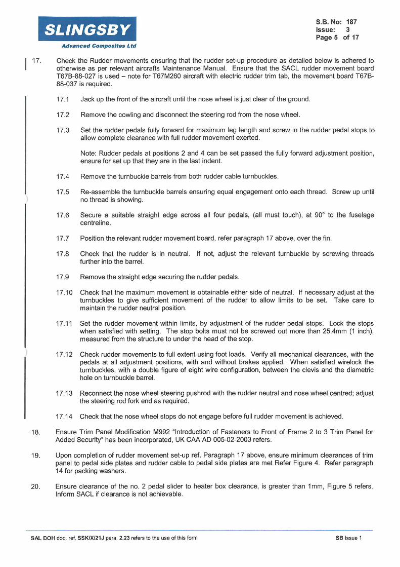
Check the Rudder movements ensuring that the rudder set-up procedure as detailed below is adhered to otherwise as per relevant aircrafts Maintenance Manual. Ensure that the SACL rudder movement board T678-88-027 is used - note for T67M260 aircraft with electric rudder trim tab, the movement board T678-88-037 is required.
17.1 Jack up the front of the aircraft until the nose wheel is just clear of the ground.
17.2 Remove the cowling and disconnect the steering rod from the nose wheel.
17.3 Set the rudder pedals fully forward for maximum leg length and screw in the rudder pedal stops to allow complete clearance with full rudder movement exerted.
Note: Rudder pedals at positions 2 and 4 can be set passed the fully forward adjustment position, ensure for set up that they are in the last indent.
17.4 Remove the turnbuckle barrels from both rudder cable turnbuckles.
17.5 Re-assemble the turnbuckle barrels ensuring equal engagement onto each thread. Screw up until no thread is showing.
17.6 Secure a suitable straight edge across all four pedals, (all must touch), at 90° to the fuselage centreline.
17.7 Position the relevant rudder movement board, refer paragraph 17 above, over the fin.
17.8 Check that the rudder is in neutral. If not, adjust the relevant turnbuckle by screwing threads further into the barrel.
17.9 Remove the straight edge securing the rudder pedals.
17.10 Check that the maximum movement is obtainable either side of neutral. If necessary adjust at the turnbuckles to give sufficient movement of the rudder to allow limits to be set. Take care to maintain the rudder neutral position.
17.11 Set the rudder movement within limits, by adjustment of the rudder pedal stops. Lock the stops when satisfied with setting. The stop bolts must not be screwed out more than 25.4mm (1 inch), measured from the structure to under the head of the stop.
17.12 Check rudder movements to full extent using foot loads. Verify all mechanical clearances, with the pedals at all adjustment positions, with and without brakes applied. When satisfied wirelock the turnbuckles, with a double figure of eight wire configuration, between the clevis and the diametric hole on turnbuckle barrel.
17.13 Reconnect the nose wheel steering pushrod with the rudder neutral and nose wheel centred; adjust the steering rod fork end as required .
17.14 Check that the nose wheel stops do not engage before full rudder movement is achieved.
18. Ensure Trim Panel Modification M992 "Introduction of Fasteners to Front of Frame 2 to 3 Trim Panel for Added Security" has been incorporated, UK CAA AD 005-02-2003 refers.
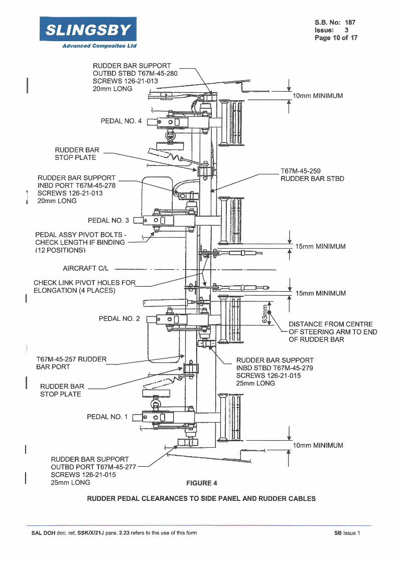
19. Upon completion of rudder movement set-up ref. Paragraph 17 above, ensure minimum clearances of trim panel to pedal side plates and rudder cable to pedal side plates are met Refer Figure 4. Refer paragraph 14 for packing washers.
20. Ensure clearance of the no. 2 pedal slider to heater box clearance, is greater than 1 mm, Figure 5 refers. Inform SACL if clearance is not achievable.
SAL DOH doc. ref. SSK/X/21J para. 2.23 refers to the use of this form SB Issue 1

21.
22.
23.
24.
25.
I 26.
27.
28.
29.
30.
31.
SLINGSBY S.B. No: 187 Issue: 3 Page 6 of 17
Advanced Composites Ltd
Ensure correct clearance of No 3 pedal to Mixture/Prop. Speed bracket; refer Paragraph 2 above, has still been maintained. If clearance has still not been achieved then contact SACL.
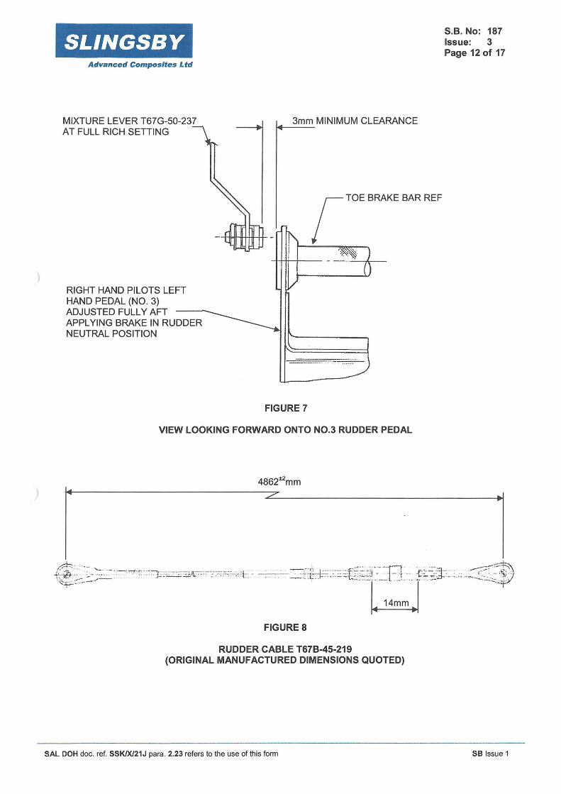
This paragraph is not applicable to aircraft with Post Mod M945 "Introduction of ISA +35°C Fuel System Improvements" incorporated. Ensure fuel pipe to rudder pedal slider clearance is met; refer T67M260 Maintenance Manual Paragraph, 5.6.5.1, the minimum acceptable clearance is now to be 5mm. If clearance cannot be achieved then; i) remove Rudder Cable and check length, length should be 4862 ±
2
mm, Figure 8 refers; ii) additionally check condition of rudder pedal assembly, refer paragraph 3, iii) if, i) and ii) do not achieve clearance remove fuel pipe, IAW relevant aircrafts Maintenance Manual, and reorientate fuel pipe. If satisfactory clearance cannot be achieved inform SACL.
Ensure head orientation of rudder cable link low pan head bolt T67M-45-570 is outboard . T67M260 Maintenance Manual Figure 5-7 refers.
Ensure Pedal no 2 Pedal pad pivot bolt head height is less than 5mm and orientated, as shown in Figure 6. A minimum of 1mm clearance is required, if not, fit part no 126-21-210 or T67B-08-981, this invokes Mod M671 "Introduction of Low Head Rudder Pedal Pad Pivot Bolts - Pedal No. 2" . If clearance is not still achieved check distance of steering arm from bar end, Figure 4 specifies. If the distance is incorrect, then return rudder bar to SACL for re-worked/new item. Alternatively if clearance of 1mm is still not achievable remove up to a maximum of 1.5mm from the steering arm screw this invokes Modification action M1029, Figure 6 refers, and paint modified screw head red.
Ensure that the requirements of SB 99, "Inspection and Rectification of Rudder Pedal Sliders", has been met. If all of the actions as quoted in SB99 have not been previously incorporated then monitor, at every 150 hours, for loose rivets until SB99 requirements are incorporated in their entirety.
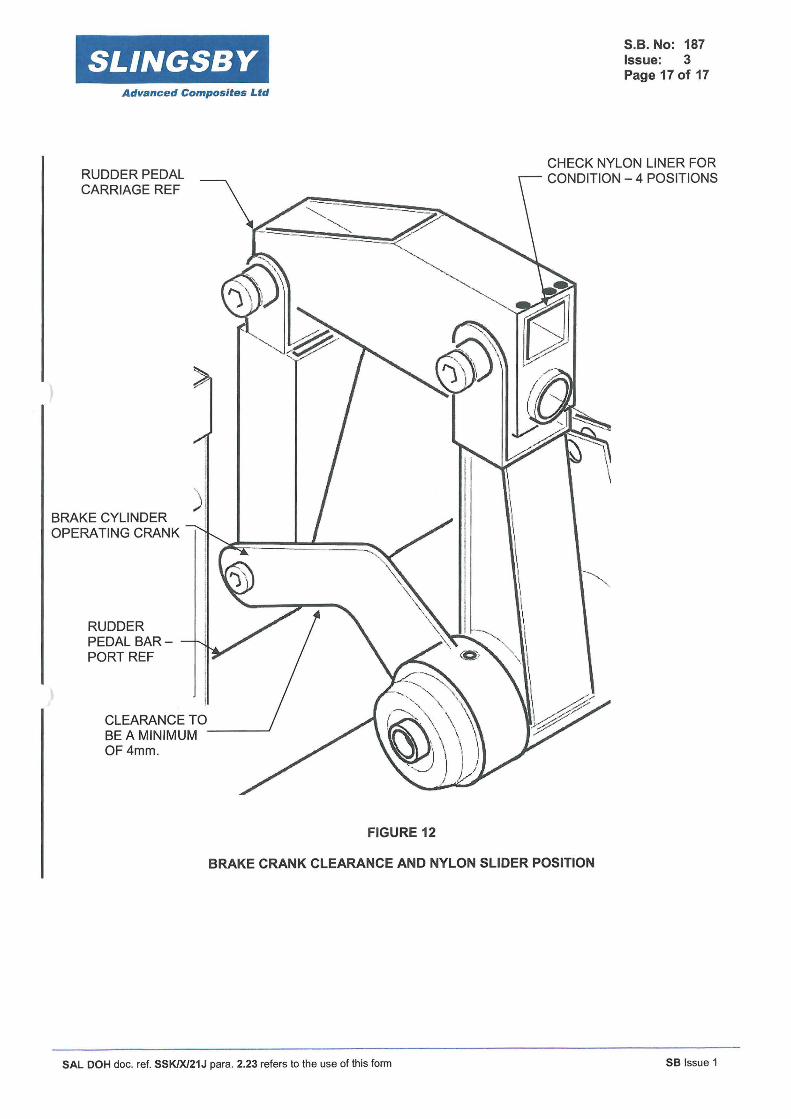
Ensure the nylon liners in the rudder pedal carriages are in good condition and not worn, Figure 12 refers, replace liners if unsatisfactory. Return carriages to SACL for replacement of liner.
Ensure, that a minimum clearance of 3mm is achieved between Pedal No 3 and Mixture Lever operating arm, refer Figure 7. Refer paragraph 14 for packing washers.
Ensure Mandatory Mod M576 has been invoked; CAA AD 013-05-94 refers. Pedal side plate should be as Figure 10.
Check structural integrity of pedal pad assembly especially around adjuster pushrod hole pedal plate, Figure 10 View on Arrow 'B' refers, if plate is cracked or damaged the pedal pad is to be repaired . Ensure riveting is secure, if rivets are loose then they have to be rectified. Contact SACL for new pedal pad assembly, materials and any applicable repair scheme.
Ensure that the brake operating crank, as shown at Figure 12, has a minimum clearance of 4mm relative to the rudder pedal bar following all checks and rectifications. Allow for various brake conditions, refer paragraph 31 .2. Should bar show signs of chaffing check depth of groove. If depth is O.Omm to 0.5mm, remove rudder bar, blend out groove, repaint and refit. If the groove is to a depth greater than 0.5mm, remove rudder bar and return to SACL for repair or replacement.
Ensure on the Annual inspection or during any maintenance in the area of the rudder pedal mechanism -e.g. trim panels removed - or upon removal of any of the rudder pedal operating mechanism, that clearances are achieved, especially in the areas noted in paragraphs 2 to 30 above.
31.1 It must be noted that during the clearance checks that the pedals do not necessarily have a direct fore and aft load applied, there will be side loads on the pedal pads deflecting the pedal pad laterally or pivoting the pedal about its slider. Also note rudder pedals at positions 2 and 4 can be set passed the fully forward adjustment position, ensure for clearance checks that they are in this position. Load is defined as adequate load to fully operate rudder pedals and brakes, with adequate side load to take up any free play that might be in the system.
SAL DOH doc. ref. SSK/X/21J para . 2.23 refers to the use of this form SB Issue 1

SLINGSBY S.B. No: 187 Issue: 3 Page 7 of 17
Advanced Composites Ltd
31.2 Ensure that the rudder pedal operating mechanism is checked for full and free movement in all aspects of normal operation and abnormal operation, e.g. application of toe brakes during extreme pedal deflections during spin recovery. Note the operation of the brakes when 'hard' will have clearances which are greater than when the brakes are 'soft', (spongy), therefore ensure safe operation and clearances throughout these conditions.
31.3 Ensure any wire locking employed, e.g. on cable turn buckles, will not foul or snag either adjacent parts or pilots clothing.
31.4 Ensure fastenings have the correct torque applied IAW T67M200 and T67M260 Maintenance Manuals as applicable, also reference can be made to Service Bulletin 141 Recommended Stiffnut Maintenance Procedures and Clarification of Existing Maintenance Manual Screw/Bolt Torque Values.
31.5 Always check the structural integrity of the rudder operating mechanism, inform SACL of any abnormality, e.g. weld cracking, excessive corrosion, etc., or if clearances cannot be met. Send components to SACL for replacement or repair, there may be a charge for this service.
31 .6 Ensure all clearance checks are undertaken at all rudder pedal adjustment positions.
31 .7 Ensure that instrument panel forward console sideplate tie bar is replaced; IPC Chap 30, Figure 2/2A refers.
31.8 On the completion of this Service Bulletin's inspection and rectification procedure, ensure that each rudder pedal mechanism clearance is still as stated and has not been affected by any subsequent adjustmenUs or rectification/s.
31.9 Ensure all cabling and ducting is secure and will be clear from the rudder pedal mechanism in all its positions, consider movement of cables, etc., e.g. when the aircraft pulls 'g', flies inverted etc. Should any unsupported cable/ducting be identified then ensure it is secured in such a manner as to clear the rudder pedal mechanism and still be able to function.
31 .10 Clearances, quoted in this Service Bulletin over-ride any clearances, quoted in the relevant aircraft Maintenance Manual.
32. If correct rudder movement and rudder operating mechanism clearances are met, annotate Logbook with, "SB 187 incorporated", at each inspection.
33. At each subsequent 300 flying hours* or Annual, whichever is soonest, inspect IAW this Service Bulletin until such time that the T67M200 and T67M260 Maintenance Manuals and Schedules are amended. Additionally, Maintenance Organisations are to ensure that the inspections contained in this Service Bulletin are added to their specific Maintenance Schedules where applicable.
*The subsequent 300 flying hours inspection will be reviewed upon customer feedback.
For further information, existing repair schemes or Mod/Service Bulletins please contact SACL Customer Support. Please note these services may be subject to a charge, unless an individual or company has a Support Agreement or Subscription Service in place. For parts and non-existing repairs a charge may be made.
SAL DOH doc. ref. SSK/X/21J para. 2.23 refers to the use of this form SB Issue 1

SLINGSBY Advanced Composites Ltd
MIXTURE/PROP SPEED SUPPORT BRACKET T67G-50-693 MOUNTED UNDER FRAME 2
PROP SPEED CABLE REF
S.B. No: 187 Issue: 3 Page 8 of 17
3mm MINIMUM CLEARANCE ,,__ __ CONTACT SACL IF
CLEARANCE CANNOT BE ACHIEVED
TOE BRAKE BAR REF
MIXTURE CABLE REF ""
RIGHT HAND PILOTS LEFT HAND PEDAL (No. 3),..., ~ FULLY FORWARD APPL YING BRAKE IN RUDDER FULL LEFT DEFLECTION
FIGURE 1 SHOWING CLEARANCE MIXTURE/PROP SPEED BRACKET TO No. 3 PEDAL
SAL DOH doc. ref. SSK/X/21J para. 2.23 refers to the use of this form SB Issue 1
SLINGSBY Advanced Composites Ltd
SPACER T67M-45-507 OR 1 OFF WASHER 126-23-748 PLUS 1 OR 2 OFF 126-23-749 WASHERS MUST BE FITTED
END FLOAT 0.0 mm TO 0.8mm MAXIMUM
CHECK BRACKET IS NOT "LOZENGED" (DEFORMED},~ REPLACE IF FOUND TO BE
PIVOT REF ..
CHECK BRACKET FOR .. SQUARENESS TO --..__ 1:\ FLOOR --....
NOTE SADDLE WASHER ORIENTATION --
i, 1.
RUDDER BAR ASSEMBLY REF
SPRING WASHER POST MOD M720
FLOOR PANEL REF
ANCHOR NUTS RIVETED TO BACKING PLATE -POST MOD M919
FIGURE 2
RUDDER BAR END FLOAT AND ITS SUPPORT BRACKET
LEFT HAND FLOOR PANEL REF.
ANCHOR NUTS ONLY -
FIGURE 3
-------
AREA OF FLOOR REQUIRING INSPECTION
SAL DOH doc. ref. SSK/X/21J para . 2.23 refers to the use of this form
S.B. No: 187 Issue: 3 Page 9 of 17
Cl)
~ 0::: co 0::: 0 LL
E E co N
0 co ~ ...... N
I ID "<:!"
~ ...... co
Cl)
~ 0::: al 0::: 0 LL
E E co (")
SB Issue 1
SLINGSBY Advanced Composites Ltd
PEDAL NO. 4
RUDDER BAR SUPPORT -~-I INBD PORT T67M-45-278 SCREWS 126-21-013 20mm LONG
PEDAL NO. 3
S.B. No: 187 Issue: 3 Page 10 of 17
_....---T67M-45-259 RUDDER BAR STBD
~'--;;;;;;iiiii=;;;!____,..,=-otT.-.-~
PEDAL ASSY PIVOT BOLTS -CHECK LENGTH IF BINDING (12 POSITIONS)
AIRCRAFT C/L
CHECK LINK PIVOT HOLES FOR'---~ ELONGATION (4 PLACES)
PEDAL NO. 2
T67M-45-257 RUDDER BAR PORT -~
RUDDER BAR --~ STOP PLATE
PEDAL NO. 1
RUDDER BAR SUPPORT OUTBD PORT T67M-45-277 SCREWS 126-21-015 25mm LONG
o[)
FIGURE 4
i """"~..-:... ____ _.L, 15mm MINIMUM
t
DIST ANGE FROM CENTRE OF STEERING ARM TO END OF RUDDER BAR
RUDDER BAR SUPPORT INBD STBD T67M-45-279 SCREWS 126-21-015 25mm LONG
10mm MINIMUM
I
RUDDER PEDAL CLEARANCES TO SIDE PANEL AND RUDDER CABLES
SAL DOH doc. ref. SSK/X/21J para. 2.23 refers to the use of this form SB Issue 1

SLINGSBY Advanced Composites Ltd
HEATER DISTRIBUTION BO~
S.B. No: 187 Issue: 3 Page 11of17
SQUARE SLIDER REF
- -
-1mm MINIMUM-,~~ CLEARANCE y ~
~---~ ......... ----~ .... -----..--.-.------...... "T""'-......-
ROUND SLIDER REF ~ FIGURE 5
PEDAL PAD REF
PEDAL NO. 2 TO HEATER BOX CLEARANCE
INCORRECT ASSEMBLY
SOCKET LOW HD SCREW 126-21-210 OR T67B-08-981
CORRECT ASSEMBLY
FIGURE 6
PEDAL NO. 2 TO STEERING ARM INTERFACE
SAL DOH doc. ref. SSK/X/21J para. 2.23 refers to the use of this form
STEERING ARM AT FULL DEFLECTION
ALLOWABLE TO REMOVE MAX 1.5mm FROM HEAD OF SOCKET HEAD SCREW TO ACHIEVE CLEARANCE - THIS ACTION INVOKES MOD M1029, SCREW TO BE IDENTIFIED AS PT NO T67B-08-547, PAINT BOLT HEAD RED.
SB Issue 1
SLINGSBY Advanced Composites Ltd
MIXTURE LEVER T67G-50-237 AT FULL RICH SETTING
RIGHT HAND PILOTS LEFT HAND PEDAL (NO. 3) ADJUSTED FULLY AFT APPL YING BRAKE IN RUDDER NEUTRAL POSITION
3mm MINIMUM CLEARANCE
r TOE BRAKE BAR REF
FIGURE 7
VIEW LOOKING FORWARD ONTO N0.3 RUDDER PEDAL
FIGURE 8
RUDDER CABLE T67B-45-219 (ORIGINAL MANUFACTURED DIMENSIONS QUOTED)
SAL DOH doc. ref. SSK/X/21J para. 2.23 refers to the use of this form
S.B. No: 187 Issue: 3 Page 12 of 17
SB Issue 1

SLINGSBY Advanced Composites Ltd
'U' BRACKET AXIS -----------.i
ENSURE 'U'BRACKET AXIS IS 90° TO RUDDER BAR AXIS
ENSURE BRACKET SIDES ARE PARALLEL TO 'U' BRACKET AXIS
BOSS REF
BRONZE BUSH REF
I
VIEW ON ARROW 'A'
35.0mm/35.5mm
8.5mm REF
CHECK FOR CRACKING HERE _ _...~
FIGURE 9
'U' BRACKET ON RUDDER BARS (4 POSITIONS)
SAL DOH doc. ref. SSK/X/21J para. 2.23 refers to the use of this form
0.5mm TYP
S.B. No: 187 Issue: 3 Page 13 of 17
RUDDER BAR AXIS
SB Issue 1

SLINGSBY Advanced Composites Ltd
PEDAL PAD UPPER (NYLON)
I ~ I 0 : ©
CUTOUT IN PAD
L------
RETAINING WASHER & ROLL PIN THRU ADUSTERROD
I
© :
S.B. No: 187 Issue: 3 Page 14 of 17
0 5mm HOLE IN PEDAL PLATE ,--- CHECK FOR CRACKING AND
DAMAGE AROUND THIS HOLE
'B' y PAD ATTACHING SCREW
@
@ --.-+-+-ADJUSTING ROD
0 0
PEDAL PLATE
VIEW ON ARROW 'B'
0
FIGURE 10
CHAMFER BOTH SIDES ON ALL PEDAL SIDEPLATES INCORPORATES MOD M576
TYPICAL RUDDER PEDAL ASSEMBLY SHOWING SIDEPLATE CHAMFERING AND PEDAL ADJUSTER ROD ATTACHMENT
SAL DOH doc. ref. SSK/X/21J para . 2.23 refers to the use of this form SB Issue 1

SLINGSBY Advanced Composites Ltd
RUDDER PEDAL CARRIAGE/SLIDER MECHANISM REAR PIVOT POSITION, (2 PLACES)
ENSURE NO DAMAGE IN FLOOR PANEL ABOUT THE BRACKET MOUNTING FASTENERS
COVERING CLOTH ____ _, FOAM BLOCK
S.B. No: 187 Issue: 3 Page 15 of 17
CHECK BRAKE MASTER CYLINDER PIN ON CARRIAGE FOR DISTORTION, CRACKING, ETC.
B- REFER FIGURE 11a
.s=~ 30mm REF
ENSURE NO GAP EXISTS AT THE BRAKE MASTER CYLINDER PIVOTS
ENSURE SUPPORT BRACKETS ARE SQUARE TO THEIR BASE & THERE IS NO DAMAGE TO THEM
IF 30mm DIMENSION IS NOT ATTAINABLE AND BRACKETS ARE SQUARE -CHECK BRACKETS ARE SQUARE TO FLOOR IF NOT THEN INFORM SACL.
FOAM BLOCK
-S-- REFERFIGURE11b
FIGURE 11 BRAKE MASTER CYLINDER SUPPORT BRACKETS
SAL DOH doc. ref. SSK/X/21J para. 2.23 refers to the use of this form SB Issue 1

SLINGSBY Advanced Composites Ltd
PORT REMOVABLE FLOOR PANEL REF -STBD SIMILAR
AREAS OF DELAMINATION EITHER SIDE OF BLOCK, FOR----' NEARL Y LENGTH OF THE BLOCK
~CHOR NUT POSITIONS t-OR BRAKE CYLINDER SUPPORT BRACKETS.
FIGURE 11a PHOTOGRAPH ON ARROW C
S.B. No: 187 Issue: 3 Page 16 of 17
BOUNDARY OF FOAM BLOCK (COLOUR OF FOAM IS WHITE)
VIEW INTO TOPSIDE OF REMOVABLE PANEL SHOWING EXTENT OF DE-LAMINATION
ANCHOR NUT POSITIONS REF
FOAM BLOCK AND ITS COVERING CLOTH REF
FIGURE 11b PHOTOGRAPH ON ARROW D
AREAS OF DELAMINATION EITHER SIDE OF BLOCK, FOR NEARLY LENGTH OF THE BLOCK
VIEW ON UNDERSIDE OF REMOVABLE PANEL SHOWING EXTENT OF DE-LAMINATION
SAL DOH doc. ref. SSK/X/21J para. 2.23 refers to the use of this form SB Issue 1
SLINGSBY Advanced Composites Ltd
RUDDER PEDAL CARRIAGE REF
BRAKE CYLINDER OPERATING CRANK
RUDDER PEDAL BARPORT REF
CLEARANCE TO BE A MINIMUM --~ OF 4mm.
FIGURE 12
S.B. No: 187 Issue: 3 Page 17 of 17
CHECK NYLON LINER FOR CONDITION - 4 POSITIONS
BRAKE CRANK CLEARANCE AND NYLON SLIDER POSITION
SAL DOH doc. ref. SSK/X/21J para. 2.23 refers to the use of this form SB Issue 1


![Cartographic Treemaps for Visualization of Public Healthcare Data · 2017. 9. 21. · Slingsby et al. [SDW10] present rectangular hierarchical car-tograms for mapping socio-economic](https://img.dokumen.tips/doc/110x75/60ff9bb2e9e29a56915038a1/cartographic-treemaps-for-visualization-of-public-healthcare-data-2017-9-21.jpg)