Embed Size (px)
Citation preview

E22" Elima-Matic Sanitarywith Metal Center Section
E2 3-A Sanitary Pump• Stainless Steel
VERSAMATIC®
Warren Rupp, Inc. • A Unit of IDEX Corporation © Copyright 2019
Warren Rupp, Inc. All rights reserved
SERVICE & OPERATING MANUALORIGINAL INSTRUCTIONS
800 North Main Street, Mansfield, OH 44902 USA Phone: (419) 526-7296 • www.versamatic.com
A Unit of IDEX Corporation
800 N. Main St.
Mansfield, OH 44902
Phone: (419) 526-7296
versamatic.com
1: P
UMP
SPEC
S2:
INST
AL &
OP
3: E
XP V
IEW
4: W
ARRA
NTY

e2mdlCsm3A-rev12191 • Model E2 3-A Sanitary www.versamatic.com
IMPORTANT
Read the safety warnings and instructions in this manual before pump installation and start-up. Failure to comply with the recommendations stated in this manual could damage the pump and void factory warranty.
When used for toxic or aggressive fluids, the pump should always be flushed clean prior to disassembly.
Airborne particles and loud noise hazards. Wear eye and ear protection.
Before maintenance or repair, shut off the compressed air line, bleed the pressure, and disconnect the air line from the pump. Be certain that approved eye protection and protective clothing are worn at all times. Failure to follow these recommendations may result in serious injury or death.
When the pump is used for materials that tend to settle out or solidify, the pump should be flushed after each use to prevent damage. In freezing temperatures the pump should be completely drained between uses.
Before pump operation, inspect all fasteners for loosening caused by gasket creep. Retighten loose fasteners to prevent leakage. Follow recommended torques stated in this manual.
CAUTION
WARNING
Plastic pumps and plastic components are not UV stabilized. Ultraviolet radiation can damage these parts and negatively af-fect material properties. Do not expose to UV light for extended periods of time.
In the event of diaphragm rupture, pumped material may enter the air end of the pump, and be discharged into the atmosphere. If pumping a product that is hazardous or toxic, the air exhaust must be piped to an appropriate area for safe containment.
This pump is pressurized internally with air pressure during operation. Make certain that all fasteners and piping connections are in good condition and are reinstalled properly during reassembly.
Take action to prevent static sparking. Fire or explosion can result, especially when handling flammable liquids. The pump, piping, valves, containers and other miscellaneous equipment must be properly grounded.
Safety Information
WARNINGPump not designed, tested or certified to be powered by compressed natural gas. Powering the pump with natural gas will void the warranty.
Use safe practices when liftingkg
WARNINGThe use of non-OEM replacement parts will void (or negate) agency certifications, including CE, ATEX, CSA, 3A and EC1935 compliance (Food Contact Materials). Warren Rupp, Inc. cannot ensure nor warrant non-OEM parts to meet the stringent requirements of the certifying agencies.
WARNINGDo not operate pump in a sterilization system as described in 3A standard 44-03 section D14.3
Place gasket between pump foot and mounting surface to keep interface clean of debri (Refer to figure below).
ANCHOR BOLT
SEALING GASKET
EQUIPMENT LEG
UNIVERSAL ALL AODD
e2mdlCsm3A-rev1219Model E2 3-A Sanitary • 2www.versamatic.com
Table of Contents
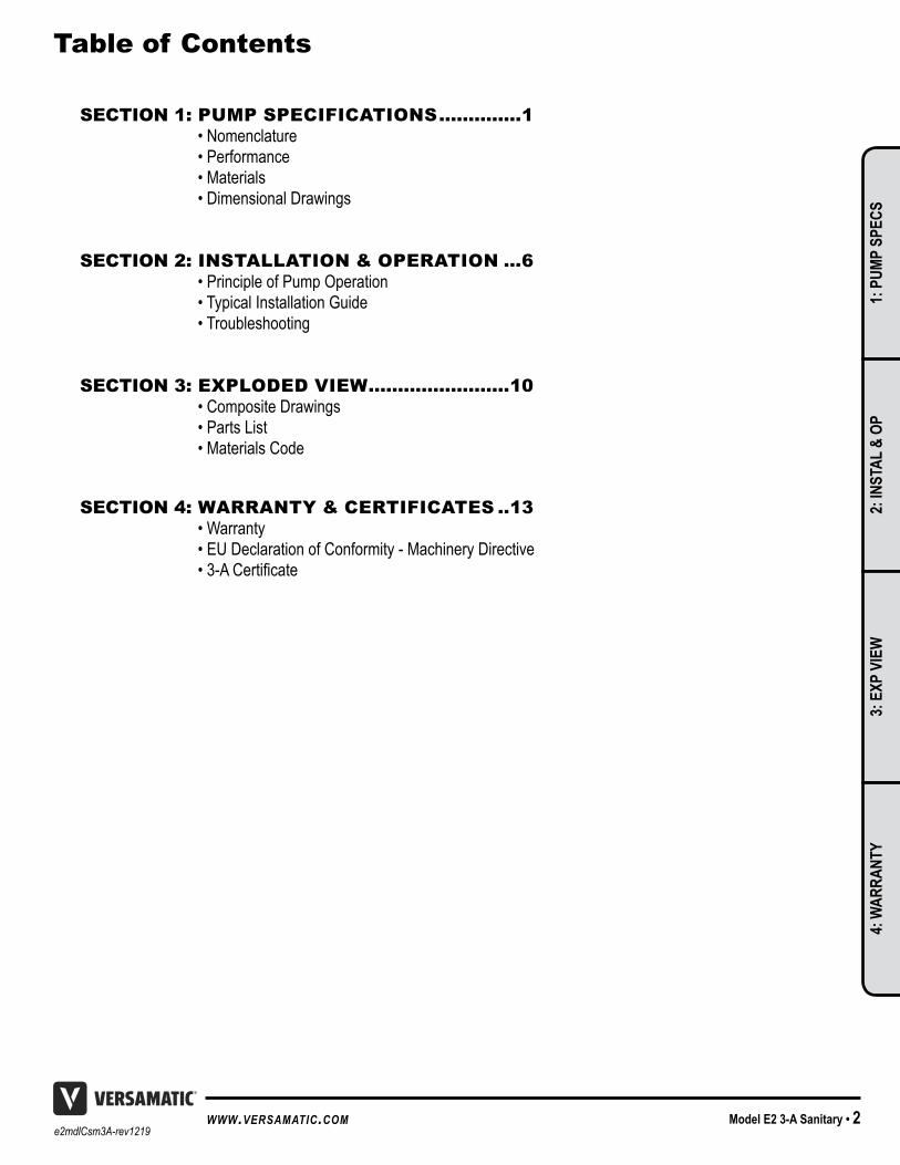
SECTION 1: PUMP SPECIFICATIONS ..............1 • Nomenclature • Performance • Materials • Dimensional Drawings
SECTION 2: INSTALLATION & OPERATION ...6 • Principle of Pump Operation • Typical Installation Guide • Troubleshooting
SECTION 3: EXPLODED VIEW ........................10 • Composite Drawings • Parts List • Materials Code
SECTION 4: WARRANTY & CERTIFICATES ..13 • Warranty • EU Declaration of Conformity - Machinery Directive •3-ACertificate
1: P
UMP
SPEC
S2:
INST
AL &
OP
3: E
XP V
IEW
4: W
ARRA
NTY
e2mdlCsm3A-rev12193 • Model E2 3-A Sanitary www.versamatic.com
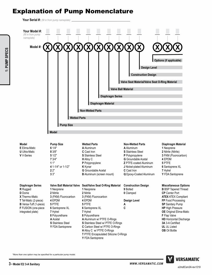
Explanation of Pump Nomenclature
*More than one option may be specified for a particular pump model.
Model Pump Size Wetted Parts Non-Wetted Parts Diaphragm MaterialE Elima-Matic 6 1/4" A Aluminum A Aluminum 1 NeopreneU Ultra-Matic 8 3/8" C Cast Iron S Stainless Steel 2 Nitrile (Nitrile)V V-Series 5 1/2" S Stainless Steel P Polypropylene 3 FKM (Fluorocarbon) 7 3/4" H Alloy C G Groundable Acetal 4 EPDM 1 1" P Polypropylene Z PTFE-coated Aluminum 5 PTFE 4 1-1/4" or 1-1/2" K Kynar J Nickel-plated Aluminum 6 Santoprene XL 2 2" G Groundable Acetal C Cast Iron 7 Hytrel 3 3" B Aluminum (screen mount) Q Epoxy-Coated Aluminum Y FDA Santoprene
Diaphragm Series Valve Ball Material Valve Seat/Valve Seat O-Ring Material Construction Design Miscellaneous OptionsR Rugged 1 Neoprene 1 Neoprene 9 Bolted B BSP Tapered ThreadD Dome 2 Nitrile 2 Nitrile 0 Clamped CP Center PortX Thermo-Matic 3 (FKM) Fluorocarbon 3 (FKM) Fluorocarbon ATEX ATEX CompliantT Tef-Matic (2-piece) 4 EPDM 4 EPDM Design Level FP Food ProcessingB Versa-Tuff (1-piece) 5 PTFE 5 PTFE A SP Sanitary PumpF FUSION (one-piece 6 Santoprene XL 6 Santoprene XL C HP High Pressureintegrated plate) 7 Hytrel 7 Hytrel OE Original Elima-Matic 8 Polyurethane 8 Polyurethane F Flap Valve A Acetal A Aluminum w/ PTFE O-Rings HD Horizontal Discharge S Stainless Steel S Stainless Steel w/ PTFE O-Rings 3A3-ACertified Y FDA Santoprene C Carbon Steel w/ PTFE O-Rings UL UL Listed H Alloy C w/ PTFE O-Rings OB Oil Bottle T PTFE Encapsulated Silicone O-Rings Y FDA Santoprene
Model
Pump Size
Wetted Parts
Non-Wetted Parts
Diaphragm Material
Diaphragm Series
Valve Ball Material
Valve Seat Material/Valve Seat O-Ring Material
Construction Design
Design Level
Options (if applicable)
Your Serial #: (fill in from pump nameplate) _____________________________________
Model #:
__ __ __ __ __ __ __ __ __ __ __ __ __(fill in from pump nameplate)
Your Model #:
1: P
UMP
SPEC
S
e2mdlCsm3A-rev1219Model E2 3-A Sanitary • 4www.versamatic.com
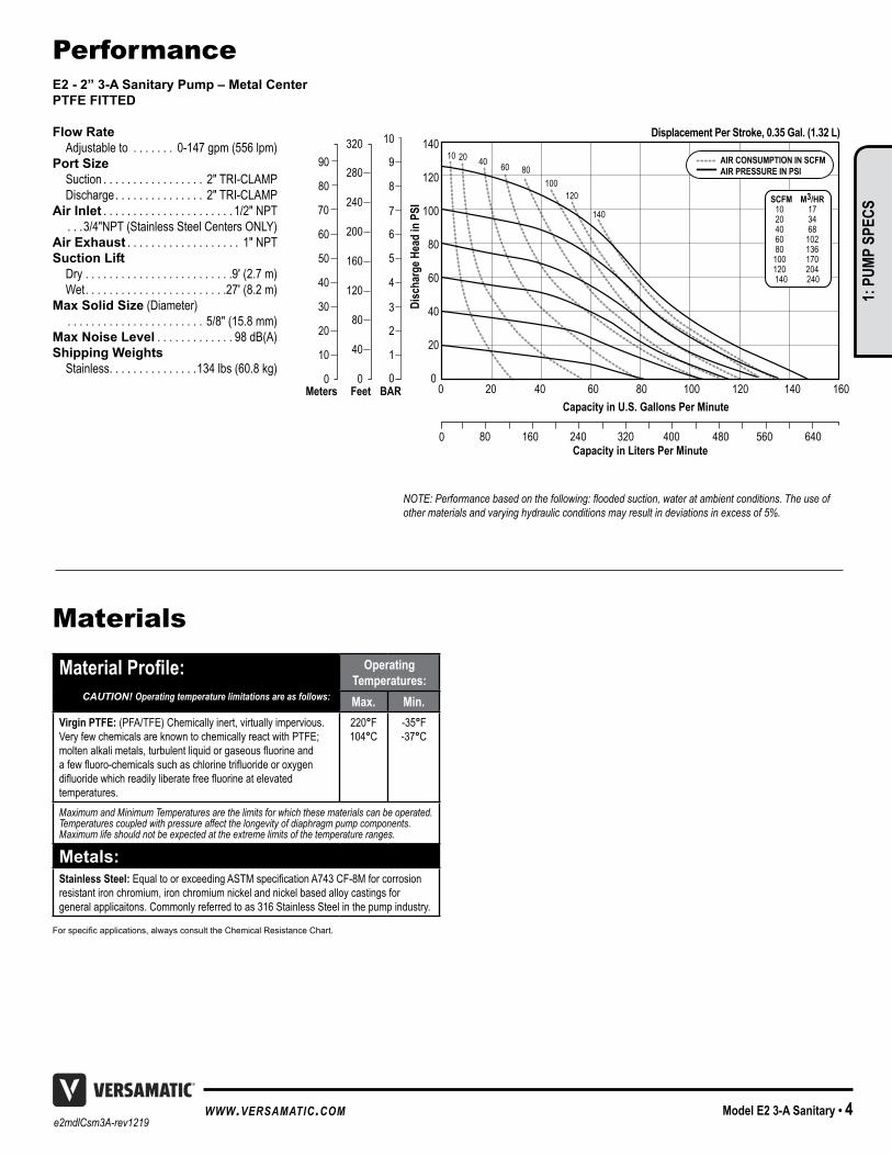
PerformanceE2 - 2” 3-A Sanitary Pump – Metal CenterPTFE FITTED
Flow Rate Adjustable to . . . . . . . 0-147 gpm (556 lpm)Port Size Suction . . . . . . . . . . . . . . . . . 2" TRI-CLAMP Discharge . . . . . . . . . . . . . . . 2" TRI-CLAMPAir Inlet . . . . . . . . . . . . . . . . . . . . . . 1/2" NPT . . .3/4"NPT (Stainless Steel Centers ONLY)Air Exhaust . . . . . . . . . . . . . . . . . . . 1" NPTSuction Lift Dry . . . . . . . . . . . . . . . . . . . . . . . . .9' (2 .7 m) Wet . . . . . . . . . . . . . . . . . . . . . . . .27' (8 .2 m)Max Solid Size (Diameter) . . . . . . . . . . . . . . . . . . . . . . . 5/8" (15 .8 mm)Max Noise Level . . . . . . . . . . . . . 98 dB(A)Shipping Weights Stainless . . . . . . . . . . . . . . .134 lbs (60 .8 kg)
Disc
harg
e Hea
d in
PSI
0
140
120
100
80
60
40
20
0
Capacity in Liters Per Minute
Capacity in U.S. Gallons Per Minute
AIR CONSUMPTION IN SCFMAIR PRESSURE IN PSI
SCFM M3/HR 10 17 20 34 40 68 60 102 80 136 100 170 120 204 140 240
0 20
80 160 240 320 400 480 560 640
10 20 40 60 80100
120
140
40 60 80 100 120 140 160
Displacement Per Stroke, 0.35 Gal. (1.32 L)
Meters Feet0 0
40
80
120
160
200
240
280
320
10
20
30
40
50
60
80
90
70
0
1
2
3
4
5
6
7
8
9
10
BAR
NOTE: Performance based on the following: flooded suction, water at ambient conditions. The use of other materials and varying hydraulic conditions may result in deviations in excess of 5%.
Materials
Material Profile: Operating Temperatures:Max. Min.
Virgin PTFE: (PFA/TFE) Chemically inert, virtually impervious . Very few chemicals are known to chemically react with PTFE; moltenalkalimetals,turbulentliquidorgaseousfluorineandafewfluoro-chemicalssuchaschlorinetrifluorideoroxygendifluoridewhichreadilyliberatefreefluorineatelevated temperatures .
220°F104°C
-35°F-37°C
Maximum and Minimum Temperatures are the limits for which these materials can be operated. Temperatures coupled with pressure affect the longevity of diaphragm pump components. Maximum life should not be expected at the extreme limits of the temperature ranges.
Metals:Stainless Steel: EqualtoorexceedingASTMspecificationA743CF-8Mforcorrosionresistant iron chromium, iron chromium nickel and nickel based alloy castings for general applicaitons . Commonly referred to as 316 Stainless Steel in the pump industry .
For specific applications, always consult the Chemical Resistance Chart.
CAUTION! Operating temperature limitations are as follows:
MODEL SPECIFIC UNIVERSAL ALL AODD
1: P
UMP
SPEC
S
e2mdlCsm3A-rev12195 • Model E2 3-A Sanitary www.versamatic.com
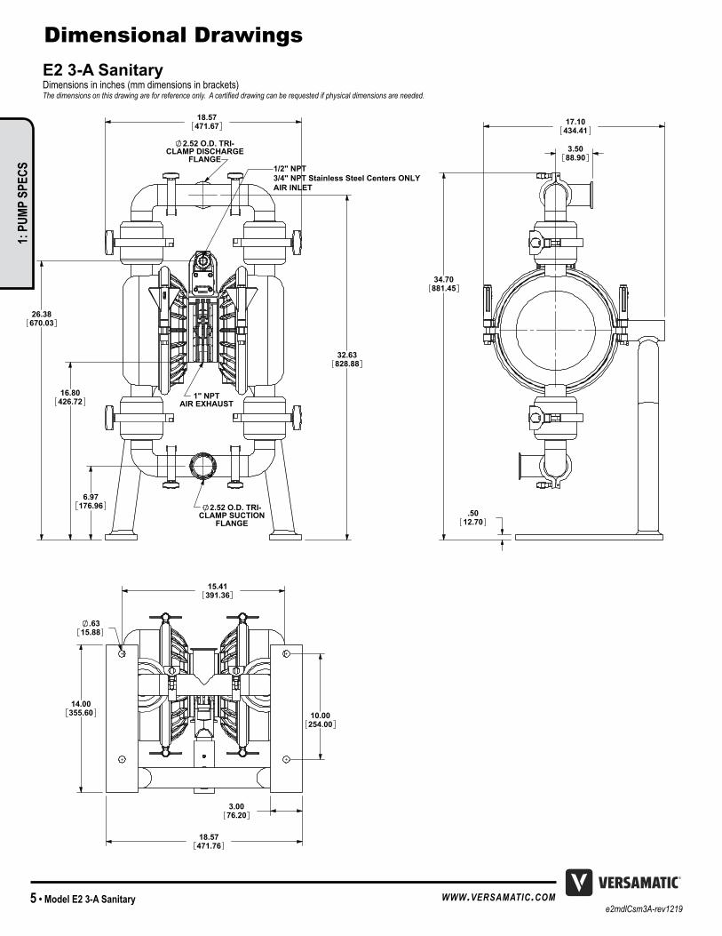
Dimensional DrawingsE2 3-A Sanitary Dimensions in inches (mm dimensions in brackets) The dimensions on this drawing are for reference only. A certified drawing can be requested if physical dimensions are needed.
6.97176.96
16.80426.72
26.38670.03
32.63828.88
18.57471.67
2.52 O.D. TRI-CLAMP DISCHARGE
FLANGE
2.52 O.D. TRI-CLAMP SUCTION
FLANGE
1" NPTAIR EXHAUST
34.70881.45
3.5088.90
17.10434.41
.5012.70
.6315.88
14.00355.60
15.41391.36
10.00254.00
18.57471.76
3.0076.20
1/2" NPT3/4" NPT Stainless Steel Centers ONLYAIR INLET
Model Specific
1: P
UMP
SPEC
S

e2mdlCsm3A-rev1219Model E2 3-A Sanitary • 6www.versamatic.com
Air-Operated Double Diaphragm (AODD) pumps are powered by compressed air or nitrogen .
The main directional (air) control valve ① distributes compressed air to an air chamber, exerting uniform pressure over the inner surface of the diaphragm ② . At the same time, the exhausting air ③ from behind the opposite diaphragm is directed through the air valve assembly(s) to an exhaust port ④ .
As inner chamber pressure (P1) exceeds liquid chamber pressure (P2), the rod ⑤ connected diaphragms shift together creating discharge on one side and suction on the opposite side . The discharged and primed liquid’s directions arecontrolledbythecheckvalves(ballorflap)⑥ orientation .
The pump primes as a result of the suction stroke . The suction stroke lowers the chamber pressure (P3) increasing the chamber volume . This results in a pressure differential necessary for atmospheric pressure (P4)topushthefluidthrough the suction piping and across the suction side check valveandintotheouterfluidchamber⑦ .
Suction (side) stroking also initiates the reciprocating (shifting, stroking or cycling) action of the pump . The suction diaphragm’s movement is mechanically pulled through its stroke . The diaphragm’s inner plate makes contact with an actuator plunger aligned to shift the pilot signaling valve . Once actuated, the pilot valve sends a pressure signal to the opposite end of the main directional air valve, redirecting the compressed air to the opposite inner chamber .
Principle of Pump Operation
SAFE AIREXHAUSTDISPOSALAREA
PUMP INSTALLATION AREA
1" DIAMETER AIREXHAUST PIPING
1" DIAMETER AIREXHAUST PIPING
1" DIAMETER AIREXHAUST PIPING
MUFFLER
LIQUIDLEVEL
SUCTIONLINE
LIQUIDLEVEL
SUCTIONLINE
MUFFLER
MUFFLER
SUBMERGED ILLUSTRATION
Pump can be submerged if the pump materials of construction are compatible with the liquid being pumped . The air exhaust must be piped above the liquid level . When the pumped product sourceisatahigherlevelthanthepump(floodedsuctioncondition), pipe the exhaust higher than the product source to prevent siphoning spills .
Air Line
Discharged Fluid
DischargeStroke Suction
Stroke
PrimedFluid
MODEL SPECIFIC
2: IN
STAL
& O
P
e2mdlCsm3A-rev12197 • Model E2 3-A Sanitary www.versamatic.com
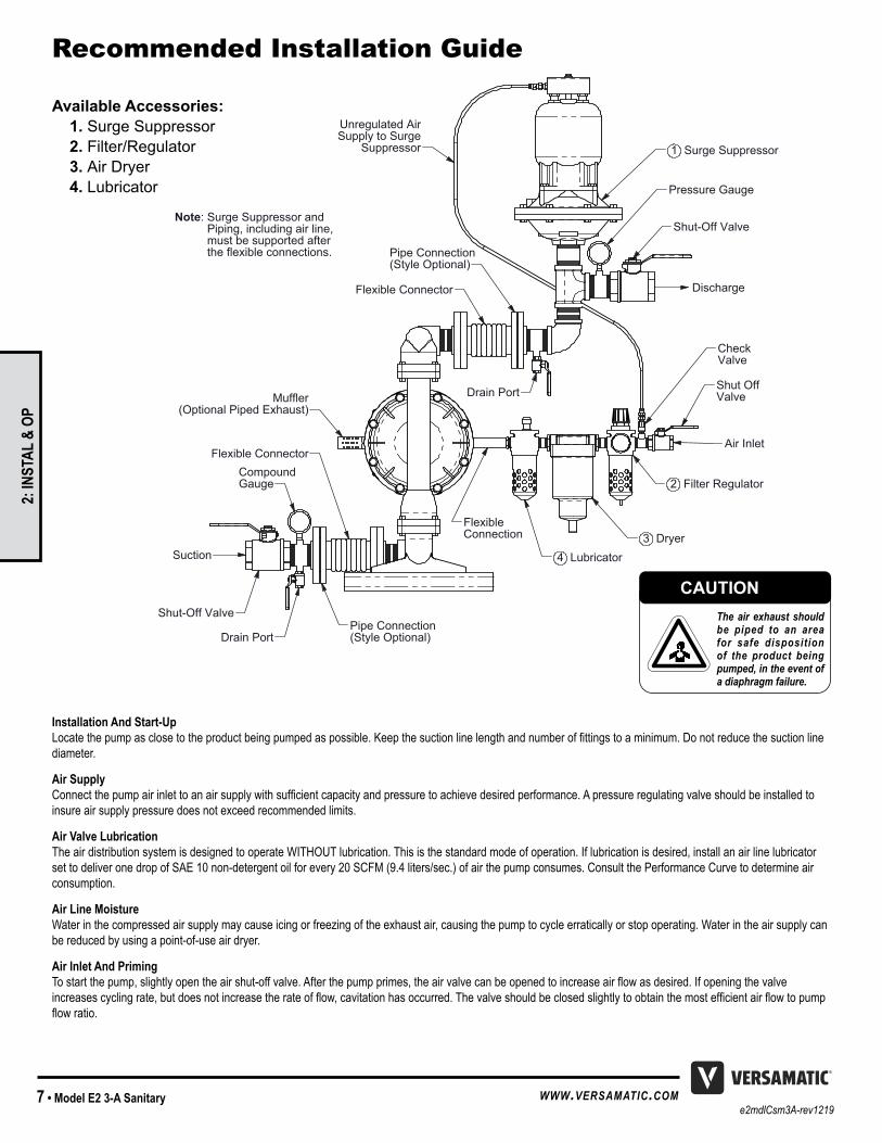
Installation And Start-Up Locatethepumpasclosetotheproductbeingpumpedaspossible.Keepthesuctionlinelengthandnumberoffittingstoaminimum.Donotreducethesuctionlinediameter .
Air Supply Connectthepumpairinlettoanairsupplywithsufficientcapacityandpressuretoachievedesiredperformance.Apressureregulatingvalveshouldbeinstalledtoinsure air supply pressure does not exceed recommended limits .
Air Valve Lubrication The air distribution system is designed to operate WITHOUT lubrication . This is the standard mode of operation . If lubrication is desired, install an air line lubricator set to deliver one drop of SAE 10 non-detergent oil for every 20 SCFM (9 .4 liters/sec .) of air the pump consumes . Consult the Performance Curve to determine air consumption .
Air Line Moisture Water in the compressed air supply may cause icing or freezing of the exhaust air, causing the pump to cycle erratically or stop operating . Water in the air supply can be reduced by using a point-of-use air dryer .
Air Inlet And Priming Tostartthepump,slightlyopentheairshut-offvalve.Afterthepumpprimes,theairvalvecanbeopenedtoincreaseairflowasdesired.Ifopeningthevalveincreasescyclingrate,butdoesnotincreasetherateofflow,cavitationhasoccurred.Thevalveshouldbeclosedslightlytoobtainthemostefficientairflowtopumpflowratio.
1 Surge Suppressor
Flexible Connector
Pipe Connection(Style Optional)
Shut-Off Valve
Pressure Gauge
Drain PortMuffler(Optional Piped Exhaust)
FlexibleConnection 3 Dryer
2 Filter Regulator
Unregulated AirSupply to Surge
Suppressor
Shut OffValve
Flexible Connector
Pipe Connection(Style Optional)Drain Port
Shut-Off Valve
CompoundGauge
Note: Surge Suppressor and Piping, including air line, must be supported after the flexible connections.
CheckValve
Air Inlet
Suction
Discharge
4 Lubricator
Recommended Installation Guide
Available Accessories: 1. Surge Suppressor 2. Filter/Regulator 3. Air Dryer 4. Lubricator
CAUTIONThe air exhaust should be piped to an area for safe disposition of the product being pumped, in the event of a diaphragm failure.
UNIVERSAL ALL AODD
2: IN
STAL
& O
P
e2mdlCsm3A-rev1219Model E2 3-A Sanitary • 8www.versamatic.com
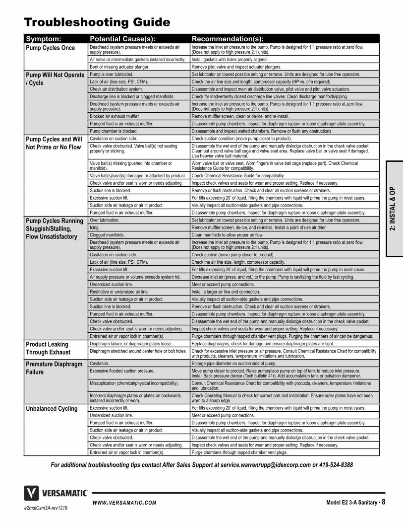
Recommended Installation Guide Troubleshooting GuideSymptom: Potential Cause(s): Recommendation(s):Pump Cycles Once Deadhead (system pressure meets or exceeds air
supply pressure) .Increasetheinletairpressuretothepump.Pumpisdesignedfor1:1pressureratioatzeroflow. (Does not apply to high pressure 2:1 units) .
Air valve or intermediate gaskets installed incorrectly . Install gaskets with holes properly aligned .Bent or missing actuator plunger . Remove pilot valve and inspect actuator plungers .
Pump Will Not Operate / Cycle
Pump is over lubricated . Set lubricator on lowest possible setting or remove . Units are designed for lube free operation .Lack of air (line size, PSI, CFM) . Check the air line size and length, compressor capacity (HP vs . cfm required) .Check air distribution system . Disassemble and inspect main air distribution valve, pilot valve and pilot valve actuators . Discharge line is blocked or clogged manifolds . Check for inadvertently closed discharge line valves . Clean discharge manifolds/piping .Deadhead (system pressure meets or exceeds air supply pressure) .
Increasetheinletairpressuretothepump.Pumpisdesignedfor1:1pressureratioatzeroflow. (Does not apply to high pressure 2:1 units) .
Blockedairexhaustmuffler. Removemufflerscreen,cleanorde-ice,andre-install.Pumpedfluidinairexhaustmuffler. Disassemble pump chambers . Inspect for diaphragm rupture or loose diaphragm plate assembly . Pump chamber is blocked . Disassembleandinspectwettedchambers.Removeorflushanyobstructions.
Pump Cycles and Will Not Prime or No Flow
Cavitation on suction side . Check suction condition (move pump closer to product) .Check valve obstructed . Valve ball(s) not seating properly or sticking .
Disassemble the wet end of the pump and manually dislodge obstruction in the check valve pocket . Clean out around valve ball cage and valve seat area . Replace valve ball or valve seat if damaged . Use heavier valve ball material .
Valve ball(s) missing (pushed into chamber or manifold) .
Wornvalveballorvalveseat.Wornfingersinvalveballcage(replacepart).CheckChemical Resistance Guide for compatibility .
Valve ball(s)/seat(s) damaged or attacked by product . Check Chemical Resistance Guide for compatibility .Check valve and/or seat is worn or needs adjusting . Inspect check valves and seats for wear and proper setting . Replace if necessary . Suction line is blocked . Removeorflushobstruction.Checkandclearallsuctionscreensorstrainers.Excessive suction lift . Forliftsexceeding20’ofliquid,fillingthechamberswithliquidwillprimethepumpinmostcases.Suction side air leakage or air in product . Visually inspect all suction-side gaskets and pipe connections .Pumpedfluidinairexhaustmuffler. Disassemble pump chambers . Inspect for diaphragm rupture or loose diaphragm plate assembly .
Pump Cycles Running Sluggish/Stalling, Flow Unsatisfactory
Over lubrication . Set lubricator on lowest possible setting or remove . Units are designed for lube free operation .Icing . Removemufflerscreen,de-ice,andre-install.Installapointofuseairdrier.Clogged manifolds . CleanmanifoldstoallowproperairflowDeadhead (system pressure meets or exceeds air supply pressure) .
Increasetheinletairpressuretothepump.Pumpisdesignedfor1:1pressureratioatzeroflow. (Does not apply to high pressure 2:1 units) .
Cavitation on suction side . Check suction (move pump closer to product) .Lack of air (line size, PSI, CFM) . Check the air line size, length, compressor capacity .Excessive suction lift . Forliftsexceeding20’ofliquid,fillingthechamberswithliquidwillprimethepumpinmostcases.Air supply pressure or volume exceeds system hd . Decreaseinletair(press.andvol.)tothepump.Pumpiscavitatingthefluidbyfastcycling.Undersized suction line . Meet or exceed pump connections . Restrictive or undersized air line . Install a larger air line and connection . Suction side air leakage or air in product . Visually inspect all suction-side gaskets and pipe connections .Suction line is blocked . Removeorflushobstruction.Checkandclearallsuctionscreensorstrainers.Pumpedfluidinairexhaustmuffler. Disassemble pump chambers . Inspect for diaphragm rupture or loose diaphragm plate assembly . Check valve obstructed . Disassemble the wet end of the pump and manually dislodge obstruction in the check valve pocket . Check valve and/or seat is worn or needs adjusting . Inspect check valves and seats for wear and proper setting . Replace if necessary .Entrained air or vapor lock in chamber(s) . Purge chambers through tapped chamber vent plugs . Purging the chambers of air can be dangerous .
Product Leaking Through Exhaust
Diaphragm failure, or diaphragm plates loose . Replace diaphragms, check for damage and ensure diaphragm plates are tight .Diaphragm stretched around center hole or bolt holes . Check for excessive inlet pressure or air pressure . Consult Chemical Resistance Chart for compatibility
with products, cleaners, temperature limitations and lubrication .Premature Diaphragm Failure
Cavitation . Enlarge pipe diameter on suction side of pump .Excessivefloodedsuctionpressure. Move pump closer to product . Raise pump/place pump on top of tank to reduce inlet pressure .
Install Back pressure device (Tech bulletin 41r) . Add accumulation tank or pulsation dampener .Misapplication (chemical/physical incompatibility) . Consult Chemical Resistance Chart for compatibility with products, cleaners, temperature limitations
and lubrication .Incorrect diaphragm plates or plates on backwards, installed incorrectly or worn .
Check Operating Manual to check for correct part and installation . Ensure outer plates have not been worn to a sharp edge .
Unbalanced Cycling Excessive suction lift . Forliftsexceeding20’ofliquid,fillingthechamberswithliquidwillprimethepumpinmostcases.Undersized suction line . Meet or exceed pump connections .Pumpedfluidinairexhaustmuffler. Disassemble pump chambers . Inspect for diaphragm rupture or loose diaphragm plate assembly .Suction side air leakage or air in product . Visually inspect all suction-side gaskets and pipe connections .Check valve obstructed . Disassemble the wet end of the pump and manually dislodge obstruction in the check valve pocket . Check valve and/or seat is worn or needs adjusting . Inspect check valves and seats for wear and proper setting . Replace if necessary . Entrained air or vapor lock in chamber(s) . Purge chambers through tapped chamber vent plugs .
For additional troubleshooting tips contact After Sales Support at [email protected] or 419-524-8388
UNIVERSAL ALL AODD, EXCEPT FLAP
2: IN
STAL
& O
P
e2mdlCsm3A-rev12199 • Model E2 3-A Sanitary www.versamatic.com
Pump Inspection and CleaningThe Elima-Matic sanitary pump can be cleaned using several techniques. However, it is important to follow guidelines set by the IAMFES, the USPHS, and the DIC and/or internal rules for inspection, cleaning and sanitization. Remove the valve balls and ball cages from the pump and clean components separate from the pump.
If the pump is to be steam cleaned, disconnect the suction line from the pump. Connect the steam line to the pump inlet. Maintain the flow of steam through the pump for at least five minutes after the temperature at the outlet has reached 200°F (94°C).
Hot water may also be used. Pump water that is maintained at minimum of 170°F (77°C) through the pump for at least five minutes. Please note that the maximum cleaning temperature of the pump is 220° (104°C).
Chemical cleaning may also be used in sanitizing the pump. Be sure to consult your distributor or the manufacturer to verify that the elastomer(s) used in the pump are compatible with the chemicals being used in the cleaning process.
2: IN
STAL
& O
P

e2mdlCsm3A-rev1219Model E2 3-A Sanitary • 10www.versamatic.com
Pump Inspection and Cleaning Composite Repair Parts Drawing
14
27
26
24
38
36
37
35
31
15
42
39
2
7
6
9
1032
16
28
4042
413
32
41
17
21
13
19
5
4
11
22
23
18
1143
825
34
33
40
43
43
29
30
20
45
45
44
LEAK DETECTOR
12
14
27
26
24
38
36
37
35
31
15
42
39
2
7
6
9
1032
16
28
4042
413
32
41
17
21
13
19
5
4
11
22
23
18
1143
825
34
33
40
43
43
29
30
20
45
45
44
LEAK DETECTOR
12
14
27
26
24
38
36
37
35
31
15
42
39
2
7
6
9
1032
16
28
4042
413
32
41
17
21
13
19
5
4
11
22
23
18
1143
825
34
33
40
43
43
29
30
20
45
45
44
LEAK DETECTOR
12
Torque Setting:300 in-lbs.(33 N-m)
Torque Setting:60 in-lbs.(6 N-m)
General Model Specific
3: E
XP V
IEW

e2mdlCsm3A-rev121911 • Model E2 3-A Sanitary www.versamatic.com
Composite Repair Parts List
Notes: 1 .) The inner diaphragm plate material is to match the air chamber material (Ref . Note 3) SV=Stainless Steel, NP=Nickle Plated
Air Valve AssemblyItem # Qty. Description Part Number
Stainless Steel Nickle PlatedAir Side Repair Kit (Includes Items
3,5,7,9,15,17,19-23) 476 .V019 .0001 1 Valve Body (includes items 2-11) 031 .V002 .110 031 .V002 .3322 1 Valve Body 095 .V001 .110 095 .V001 .3323 1 Valve Body Gasket P24-2024 1 Valve Sleeve 755 .V006 .1485 6 O-ring 560 .206 .3606 1 Valve Spool Assembly (Includes items 7) 775 .V001 .0007 6 Glyde Ring Assembly P34-204F8 1 Air Valve Screen P34-210 P24-2109 2 End Cap Gasket P24-205
10 2 End Cap SP34-30011 13 Mounting Screws (8 included on item 1) S100112 5 Cap 165 .161 .000
Center Section AssemblyItem # Qty. Description Part Number
Stainless Steel Nickle Plated13 1 Center Block Assembly (Includes item 14 & 15) SP24-400 3A P24-4003ANP ASY14 2 Bearing Sleeve P31-40315 2 Main Shaft O-Ring P24-40316 2 Air Chamber 196 .V002 .110 3A17 2 Air Chamber Gasket 360 .V001 .36018 8 Bolt SP24-110
Pilot Repair Kit (Includes Items 19-23) 476 .V018 .00019 1 Pilot Sleeve Assembly (include item 20) 755 .V002 .00020 6 O-ring 560 .101 .35821 1 Retaining Ring 675 .037 .08022 1 Pilot Spool Assembly (Includes item 23) 775 .V002 .00023 8 O-ring 560 .023 .35824 1 Stand Attachment SP24-65125 2 Stand Attachment Pin P29-65426 1 Stand SP29-650CP27 1 Stand Locking Pin P29-65228 1 Muffler 530 .033 .000
Diaphragm Assembly / ElastomersItem # Qty. Description Part Number
29 1 Main Shaft P24-103F30 2 Diaphragm V224F31 2 Bumper Washer P24-50132 4 Valve Ball V241TF33 4 Manifold Tee Seal V275TF34 4 Manifold Elbow Seal V276TF
Wet End AssemblyItem # Qty. Description Part Number
35 2 Water Chamber D29-23536 4 Large Clamp Half SV230A37 4 Bolt SV230C38 4 Wing Nut FG30D39 2 ManifoldTee D29-23840 4 Manifold Elbow D29-23741 4 Ball Cage 670 .V003 .11042 4 Manifold Elbow Clamp V275A43 4 Manifold Tee Clamp V276A44 1 Leak Detector P29-80045 2 Leak Detector Probe P29-804
MODEL SPECIFIC
3: E
XP V
IEW
e2mdlCsm3A-rev1219Model E2 3-A Sanitary • 12www.versamatic.com
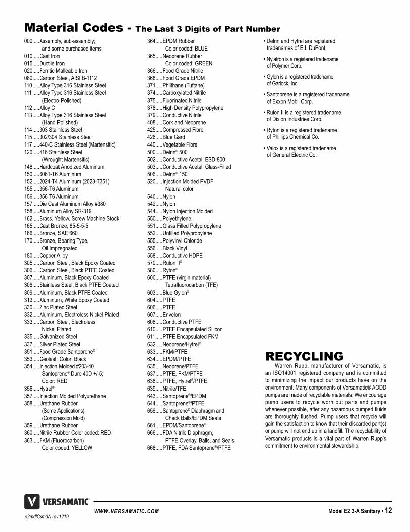
Material Codes - The Last 3 Digits of Part Number000 . . . . .Assembly, sub-assembly;
and some purchased items010 . . . . .Cast Iron015 . . . . .Ductile Iron020 . . . . .Ferritic Malleable Iron080 . . . . .Carbon Steel, AISI B-1112110 . . . . .Alloy Type 316 Stainless Steel111 . . . . .Alloy Type 316 Stainless Steel
(Electro Polished)112 . . . . .Alloy C113 . . . . .Alloy Type 316 Stainless Steel
(Hand Polished)114 . . . . .303 Stainless Steel115 . . . . .302/304 Stainless Steel117 . . . . .440-C Stainless Steel (Martensitic)120 . . . . .416 Stainless Steel
(Wrought Martensitic)148 . . . . .Hardcoat Anodized Aluminum150 . . . . .6061-T6 Aluminum152 . . . . .2024-T4 Aluminum (2023-T351)155 . . . . .356-T6 Aluminum156 . . . . .356-T6 Aluminum157 . . . . .Die Cast Aluminum Alloy #380158 . . . . .Aluminum Alloy SR-319162 . . . . .Brass, Yellow, Screw Machine Stock165 . . . . .Cast Bronze, 85-5-5-5166 . . . . .Bronze, SAE 660170 . . . . .Bronze, Bearing Type,
Oil Impregnated180 . . . . .Copper Alloy305 . . . . .Carbon Steel, Black Epoxy Coated306 . . . . .Carbon Steel, Black PTFE Coated307 . . . . .Aluminum, Black Epoxy Coated308 . . . . .Stainless Steel, Black PTFE Coated309 . . . . .Aluminum, Black PTFE Coated313 . . . . .Aluminum, White Epoxy Coated330 . . . . .Zinc Plated Steel332 . . . . .Aluminum, Electroless Nickel Plated333 . . . . .Carbon Steel, Electroless
Nickel Plated335 . . . . .Galvanized Steel337 . . . . .Silver Plated Steel351 . . . . .Food Grade Santoprene®
353 . . . . .Geolast; Color: Black354 . . . . .Injection Molded #203-40
Santoprene® Duro 40D +/-5; Color: RED
356 . . . . .Hytrel®357 . . . . .Injection Molded Polyurethane358 . . . . .Urethane Rubber
(Some Applications) (Compression Mold)
359 . . . . .Urethane Rubber360 . . . . .Nitrile Rubber Color coded: RED363 . . . . .FKM (Fluorocarbon)
Color coded: YELLOW
364 . . . . .EPDM Rubber Color coded: BLUE
365 . . . . .Neoprene Rubber Color coded: GREEN
366 . . . . .Food Grade Nitrile368 . . . . .Food Grade EPDM371 . . . . .Philthane (Tuftane)374 . . . . .Carboxylated Nitrile375 . . . . .Fluorinated Nitrile378 . . . . .High Density Polypropylene379 . . . . .Conductive Nitrile408 . . . . .Cork and Neoprene425 . . . . .Compressed Fibre426 . . . . .Blue Gard440 . . . . .Vegetable Fibre500 . . . . .Delrin® 500502 . . . . .Conductive Acetal, ESD-800503 . . . . .Conductive Acetal, Glass-Filled506 . . . . .Delrin® 150520 . . . . .Injection Molded PVDF
Natural color540 . . . . .Nylon542 . . . . .Nylon544 . . . . .Nylon Injection Molded550 . . . . .Polyethylene551 . . . . .Glass Filled Polypropylene552 . . . . .UnfilledPolypropylene555 . . . . .Polyvinyl Chloride556 . . . . .Black Vinyl558 . . . . .Conductive HDPE570 . . . . .Rulon II®
580 . . . . .Ryton®
600 . . . . .PTFE (virgin material) Tetrafluorocarbon(TFE)
603 . . . . .Blue Gylon®
604 . . . . .PTFE 606 . . . . .PTFE 607 . . . . .Envelon608 . . . . .Conductive PTFE610 . . . . .PTFE Encapsulated Silicon611 . . . . .PTFE Encapsulated FKM632 . . . . .Neoprene/Hytrel®633 . . . . .FKM/PTFE 634 . . . . .EPDM/PTFE 635 . . . . .Neoprene/PTFE 637 . . . . .PTFE, FKM/PTFE 638 . . . . .PTFE, Hytrel®/PTFE 639 . . . . .Nitrile/TFE643 . . . . .Santoprene®/EPDM644 . . . . .Santoprene®/PTFE 656 . . . . .Santoprene® Diaphragm and
Check Balls/EPDM Seats661 . . . . .EPDM/Santoprene®
666 . . . . .FDA Nitrile Diaphragm, PTFE Overlay, Balls, and Seals
668 . . . . .PTFE, FDA Santoprene®/PTFE
• Delrin and Hytrel are registered tradenames of E .I . DuPont .
• Nylatron is a registered tradename of Polymer Corp .
• Gylon is a registered tradename of Garlock, Inc .
• Santoprene is a registered tradename of Exxon Mobil Corp .
• Rulon II is a registered tradename of Dixion Industries Corp .
• Ryton is a registered tradename of Phillips Chemical Co .
• Valox is a registered tradename of General Electric Co .
RECYCLINGWarren Rupp, manufacturer of Versamatic, is
an ISO14001 registered company and is committed to minimizing the impact our products have on the environment . Many components of Versamatic® AODD pumps are made of recyclable materials . We encourage pump users to recycle worn out parts and pumps wheneverpossible,afteranyhazardouspumpedfluidsare thoroughly flushed. Pump users that recyclewillgain the satisfaction to know that their discarded part(s) orpumpwillnotendupinalandfill.TherecyclabilityofVersamatic products is a vital part of Warren Rupp’s commitment to environmental stewardship .

e2mdlCsm3A-rev121913 • Model E2 3-A Sanitary www.versamatic.com
DATE: February 27, 2017FECHA: DATUM:DATA:DATO:PÄIVÄYS:
AUTHORIZED / APPROVED BY: Approuve par: Aprobado por: Genehmigt von: approvato da: Goedgekeurd door: Underskrift: Valtuutettuna: Bemyndiget av: Autorizado Por:
06/14/2017 REV 08 VMQR 044FM
This product complies with the following European Community Directives: Ce produit est conforme aux directives de la Communauté européenne suivantes: Este producto cumple con las siguientes Directrices de la Comunidad Europea: Dieses produkt erfüllt die folgenden Vorschriften der Europäischen Gemeinschaft: Questo prodotto è conforme alle seguenti direttive CEE: Dir produkt voldoet aan de volgende EG-richtlijnen: Denna produkt överensstämmer med följande EU direktiv: Versamatic, Inc., erklærer herved som fabrikant, at ovennævnte produkt er i overensstemmelse med bestemmelserne i Direkktive:Tämä tuote täyttää seuraavien EC Direktiivien vaatimukstet:Dette produkt oppfyller kravene til følgende EC Direktiver:Este produto está de acordo com as seguintes Directivas comunitárias:
MANUFACTURED BY:FABRIQUE PAR:FABRICADA POR:HERGESTELLT VON:FABBRICATO DA:VERVAARDIGD DOOR:TILLVERKAD AV:FABRIKANT:VALMISTAJA:PRODUSENT:FABRICANTE:
DECLARATION DE CONFORMITE • DECLARACION DE CONFORMIDAD • ERKLÄRUNG BEZÜGLICH EINHALTUNG DER VORSCHRIFTENDICHIARAZIONE DI CONFORMITÀ • CONFORMITEITSVERKLARING • DEKLARATION OM ÖVERENSSTÄMMELSE
EF-OVERENSSTEMMELSESERKLÆRING • VAATIMUSTENMUKAISUUSVAKUUTUS • SAMSVARSERKLÄRING DECLARAÇAO DE CONFORMIDADE
VERSAMATIC ®
Warren Rupp, Inc.A Unit of IDEX Corporation 800 North Main Street P.O. Box 1568 Mansfield, OH 44901-1568 USA
Tel: 419-526-7296Fax: 419-526-7289
This product has used the following harmonized standards to verify conformance: EN809:2012Ce materiel est fabriqué selon les normes harmonisées suivantes, afin d’ en garantir la conformité:Este producto cumple con las siquientes directrices de la comunidad europa:Dieses produkt ist nach folgenden harmonisierten standards gefertigtworden, die übereinstimmung wird bestätigt:Questo prodotto ha utilizzato i seguenti standards per verificare la conformita´:De volgende geharmoniseerde normen werden gehanteerd om de conformiteit van dit produkt te garanderen: För denna produkt har följande harmoniserande standarder använts för att bekräfta överensstämmelse:Harmoniserede standarder, der er benyttet:Tässä tuotteessa on sovellettu seuraavia yhdenmukaistettuja standardeja:Dette produkt er produsert i overenstemmelse med fløgende harmoniserte standarder:Este produto utilizou os seguintes padrões harmonizados para varificar conformidade:
PUMP MODEL SERIES: E SERIES, V SERIES, VT SERIES, VSMA3, SPA15, RE SERIES AND U2 SERIES
Dave Roseberry
Authorized Representative:IDEX Pump TechnologiesR79 Shannon Industrial Estate,Shannon, Co. Clare IrelandAttn: Barry McMahon
Director of Engineering
DECLARATION OF CONFORMITY
2006/42/ECon Machinery, according
to Annex VIII
5 - YEAR Limited Product WarrantyQuality System ISO9001 Certified • Environmental Management Systems ISO14001 Certified
Versamatic warrants to the original end-use purchaser that no product sold by Versamatic that bears a Versamatic brand shall fail undernormal use and service due to a defect in material or workmanship within five years from the date of shipment from Versamatic’s factory.
The use of non-OEM replacement parts will void (or negate) agency certifications, including CE, ATEX, CSA, 3A and EC1935 compliance (Food Contact Materials). Warren Rupp, Inc. cannot ensure nor warrant non-OEM parts to meet the stringent requirements of the certifying agencies.
~ See complete warranty at http://vm.salesmrc.com/pdfs/VM_Product_Warranty.pdf
MODEL SPECIFIC
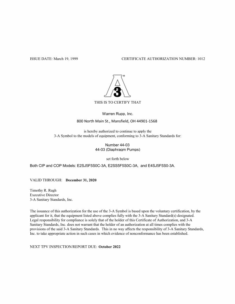
Warren Rupp, Inc.
44-03 (Diaphragm Pumps)
Both CIP and COP Models: E2SJ5F5S0C-3A, E2SS5F5S0C-3A, and E4SJ5F5S0-3A.
THIS IS TO CERTIFY THAT
is hereby authorized to continue to apply the3-A Symbol to the models of equipment, conforming to 3-A Sanitary Standards for:
set forth below
Timothy R. RughExecutive Director3-A Sanitary Standards, Inc.
CERTIFICATE AUTHORIZATION NUMBER: 1012ISSUE DATE: March 19, 1999
VALID THROUGH:
NEXT TPV INSPECTION/REPORT DUE:
800 North Main St., Mansfield, OH 44901-1568
Number 44-03
December 31, 2020
October 2022
The issuance of this authorization for the use of the 3-A Symbol is based upon the voluntary certification, by the applicant for it, that the equipment listed above complies fully with the 3-A Sanitary Standard(s) designated. Legal responsibility for compliance is solely that of the holder of this Certificate of Authorization, and 3-A Sanitary Standards, Inc. does not warrant that the holder of an authorization at all times complies with the provisions of the said 3-A Sanitary Standards. This in no way affects the responsibility of 3-A Sanitary Standards, Inc. to take appropriate action in such cases in which evidence of nonconformance has been established.