Embed Size (px)
DESCRIPTION
http://www.eao.com/enl/nl/products/Documentatie/Series_EAO/series84_201110.pdf
Citation preview

EAO – Your Expert Partner for Human Machine Interfaces
EAO Product Information
Series 84


84Switches and Indicators

84Contents
205.2009
Description ...................................................................................................... 3
Product Assembly .......................................................................................... 4
Mounting instruction ...................................................................................... 6
Devices raised mounting ............................................................................... 7
Devices flush mounting ................................................................................. 9
Accessories................................................................................................... 13
Technical Data............................................................................................... 27
Application guidelines.................................................................................. 30
Drawings........................................................................................................ 31
Index............................................................................................................... 45

305.2009
84Description
General notesThe Series 84 consists of indicators, pushbuttons and emergency-stop switches. The indicators and pushbuttons are a modular system of lens, actuator, switching element and a variety of means of connection and mounting. Different front protection of IP 67, IP 65 or IP 40 ensure that the pushbuttons are suited for industrial use.Anodized aluminium parts can have visible variations due production-technical reasons.
MountingThe actuators of the Series 84 are inserted in a 22.5 mm diameter mounting hole and the switching units are clipped on to the rear of the actuators. The pushbutton system can be mounted as a complete unit (actuator and switching unit). Mounting from the front with the wiring already attached is also possible.When mounted on printed circuit boards the actuators are inserted in the mounting hole 22.5 mm dia. and the switching elements are fixed on the board. The printed circuit board is connected to the preassembled actuator by means of the mounting flange. There is no need for subsequent adjustment or spacing studs.
LensesThe lenses are available in various colours and made either from plastic or anodized aluminium.
MarkingThe marking plates of the Series 84 can be marked by engraving or hot stamping.Specific symbols and markings are available on request.The lenses are without holder not engravable, since by mounting no accurate position of the engraving text is reached.
IlluminationTo ensure full illumination, the switching elements can be supplied with integrated single LEDs in the colours red, orange, yellow, green, blue or white. The series resistor is integrated.Luminosity and wave length scattering caused by the technology used in the LED manufacturing processes may lead to visual differences in our products.
Emergency-stop pushbutton, foolproofThe E-stop pushbutton can be mounted in front panels with a thickness between 1 and 4 mm. It has a low behind-panel depth of 13.5 mm (max.) respectively 18.5 mm with plug-in terminlas and can be safely and easily adapted to PCBs of different heights. The front protection degree is IP 65.Importantly, the Series 84 emergency-stop requires no additional assembly because of its single-piece 'monoblock' design.The switch's status is clearly indicated by a black or green colour ring on the shaft, and the foolproof actuator design conforms to DIN EN ISO 13850 and EN IEC 60947.It can be supplied with LED illumination that is visible even from the side.
Specimen order0
We reserve the right to modify technical dataAll dimensions in mm
Product Information Indicator :- Indicator actuator, IP67 84-0100.0Essential accessories :- Lens plastic blue 84-7111.600- Illumination element
Single-LED blue 24VDC, plug-in terminal84-8001.6620
or
Indicator with PCB terminal :- Indicator actuator, IP67 84-3100.1Essential accessories :- Lens plastic red 84-7111.200- Illumination element with PCB terminal 92-800.042- Single-LED red 2.1VDC 10-2602.3202L- Mounting flange 92-960.0

84Product Assembly
405.2009
Indicator and pushbutton illuminative, 25 mm dia.
0 1 Lens2 Marking plate3 Lens holder4 Actuator housing5 Outer sealing6 Inner sealing7 Front panel8 Fixing nut9 Switching-/Illumination element with plug-in terminal (solderable)
Indicator and pushbutton illuminative, 40 mm dia.
0 1 Lens2 Marking plate3 Lens holder4 Actuator housing5 Sealing6 Front panel7 Fixing nut8 Switching-/Illumination element with flat ribbon cable
1
2
3
7
4
5
6
8
9
1
2
3
6
4
5
7
8

84Product Assembly
505.2009
Indicator and pushbutton illuminative, 25 mm dia., PCB version
0 1 Lens2 Marking plate3 Lens holder4 Actuator housing5 Sealing6 Front panel7 Fixing nut8 Mounting flange9 Switching-/Illumination element with PCB terminal10 PCB11 Fixing screws
Emergency-stop pushbutton
0 1 Emergency-stop pushbutton2 Fixing nut3 Position indication ring green or black
1
2
3
7
4
5
6
8
9
10
11
1
3
2

84Mounting instruction
605.2009
0
The arrangement of the mounting flanges and their number is determined by the size ofthe front panel or PCB. To ensure uniform, tactile switching, we recommend a layout ofthe flanges as per adjacent sketch.
For large PCBs with several switching elements we recommend the following procedure :
1. Fit the actuator to the front panel.2. Clip the mounting flange to the rear of the intended actuator.3. Screw the PCB with the components soldered to it to the assembled mounting flange.
This arrangement applies to PCBs 1.6 mm thick.>
The tool 84-998 must be used for removing the mounting flange from the actuator. Before removing the flange, the PCB fixing srews must be loosened.
Arrangement mounting flange for switching- and illumination element, PCB mounting
Dismantling mounting flange

84Devices raised mounting
710.2011
Application as per DIN EN ISO 13850 and EN 60204-1
Continuation see next page
Standard version: Flat ribbon-cable length 300 mm; Plug-in terminal 2.8 x 0.5 mm.Other options on request: Customisation of flat ribbon-cable and connectors.Switching action: MA = Maintained action Terminals: FR = Flat ribbon cable, PT 2.8 s = Plug-in terminal 2.8 mm (solderable) Contacts: NC = Normally closed, NO = Normally open Component layout from page 31, Mounting dimensions from page 34, Technical drawing from page 35, Circuit drawing from page 43
Emergency-stop pushbutton, foolproof EN IEC 60947-5-5, complete
Fron
t pro
tect
ion
Sw
itchi
ng a
ctio
n
Mushroom had cap Ill
umin
atio
n
Term
inal
s
ContactsØ 32 mm Typ-Nr. C
ompo
nent
layo
utM
ount
ing
dim
ensi
ons
Tech
nica
l dra
win
g
Circ
uit d
raw
ing
e
Emergency-stop pushbutton, foolproof EN IEC 60947-5-5, complete Position indication ring black Twist to unlock clockwise
IP 65 MA Plastic red without FR 1 NC 84-5020.0040 2 2 17 8 0.0361 NC + 1 NO 84-5030.0040 2 2 17 9 0.0362 NC 84-5040.0040 2 2 17 10 0.036
PT 2.8 s 1 NC 84-5020.0020 1 2 17 8 0.0281 NC + 1 NO 84-5030.0020 1 2 17 9 0.0282 NC 84-5040.0020 1 2 17 10 0.028
Position indication ring black Twist to unlock clockwise LED operating voltage: 5 ... 30 VDC Current consumption: 9.7 ...12.4 mA
IP 65 MA Plastic red LED red FR 1 NC 84-5021.2B40 2 2 17 11 0.0361 NC + 1 NO 84-5031.2B40 2 2 17 12 0.0362 NC 84-5041.2B40 2 2 17 13 0.036
PT 2.8 s 1 NC 84-5021.2B20 1 2 17 11 0.0281 NC + 1 NO 84-5031.2B20 1 2 17 12 0.0282 NC 84-5041.2B20 1 2 17 13 0.028
Position indication ring green Twist to unlock clockwise
IP 65 MA Plastic red without FR 1 NC 84-5120.0040 2 2 17 8 0.0361 NC + 1 NO 84-5130.0040 2 2 17 9 0.0362 NC 84-5140.0040 2 2 17 10 0.036
PT 2.8 s 1 NC 84-5120.0020 1 2 17 8 0.0281 NC + 1 NO 84-5130.0020 1 2 17 9 0.0282 NC 84-5140.0020 1 2 17 10 0.028
Position indication ring green Twist to unlock clockwise LED operating voltage: 5 ... 30 VDC Current consumption: 9.7 ... 12.4 mA
IP 65 MA Plastic red LED red FR 1 NC 84-5121.2B40 2 2 17 11 0.0361 NC + 1 NO 84-5131.2B40 2 2 17 12 0.0362 NC 84-5141.2B40 2 2 17 13 0.036
PT 2.8 s 1 NC 84-5121.2B20 1 2 17 10 0.0281 NC + 1 NO 84-5131.2B20 1 2 17 12 0.0282 NC 84-5141.2B20 1 2 17 13 0.028

84Devices raised mounting
810.2011
Continuation see next page
Standard version: Flat ribbon-cable length 300 mm; Plug-in terminal 2.8 x 0.5 mm.Other options on request: Customisation of flat ribbon-cable and connectors.Switching action: MA = Maintained action Terminals: FR = Flat ribbon cable, PT 2.8 s = Plug-in terminal 2.8 mm (solderable) Contacts: NC = Normally closed, NO = Normally open Component layout from page 31, Mounting dimensions from page 34, Technical drawing from page 35, Circuit drawing from page 43
Stop pushbutton grey, complete
Fron
t pro
tect
ion
Sw
itchi
ng a
ctio
n
Mushroom had cap Ill
umin
atio
n
Term
inal
s
ContactsØ 32 mm Typ-Nr. C
ompo
nent
layo
utM
ount
ing
dim
ensi
ons
Tech
nica
l dra
win
g
Circ
uit d
raw
ing
e
Stop pushbutton grey, complete Position indication ring black Twist to unlock clockwise
IP 65 MA Plastic grey without FR 1 NC 84-6820.0040 2 2 17 8 0.0361 NC + 1 NO 84-6830.0040 2 2 17 9 0.0362 NC 84-6840.0040 2 2 17 10 0.036
PT 2.8 s 1 NC 84-6820.0020 1 2 17 8 0.0281 NC + 1 NO 84-6830.0020 1 2 17 9 0.0282 NC 84-6840.0020 1 2 17 10 0.028
Position indication ring black Twist to unlock clockwise LED operating voltage: 5 ... 30 VDC Current consumption: 9.7 ...12.4 mA
IP 65 MA Plastic grey LED red FR 1 NC 84-6821.2B40 2 2 17 11 0.0361 NC + 1 NO 84-6831.2B40 2 2 17 12 0.0362 NC 84-6841.2B40 2 2 17 13 0.036
PT 2.8 s 1 NC 84-6821.2B20 1 2 17 11 0.0281 NC + 1 NO 84-6831.2B20 1 2 17 12 0.0282 NC 84-6841.2B20 1 2 17 13 0.028

84Devices flush mounting
905.2009
Illuminated lens, non-illuminated bezel
Essential Accessories:d Illumination element page 17d Lens plastic page 13Continuation see next page
Mounting dimensions from page 34, Technical drawing from page 35
Illuminated lens, non-illuminated bezel
Essential Accessories:d Lens plastic page 13d Switching element illuminated page 19Continuation see next page
Switching action: M = Momentary actionMounting dimensions from page 34, Technical drawing from page 35, Circuit drawing from page 43
Indicator actuator
Fron
t pro
tect
ion
Front ringØ 25 mmTyp-Nr. M
ount
ing
dim
ensi
ons
Tech
nica
l dra
win
g
e
Indicator actuator IP 40 Plastic black 84-3100.0 1 16 0.004IP 67 Aluminium natural 84-0200.7 1 16 0.008
Plastic black 84-0100.0 1 16 0.003
Illuminated pushbutton actuator
Sw
itchi
ng a
ctio
n
Fron
t pro
tect
ion
Front ringØ 40 mmTyp-Nr.
Ø 25 mmTyp-Nr. M
ount
ing
dim
ensi
ons
Tech
nica
l dra
win
g
Circ
uit d
raw
ing
e
Illuminated pushbutton actuator M IP 67 Aluminium natural 84-1221.7 3 18 4 0.022IP 40 Plastic black 84-2101.0 1 16 4 0.004IP 67 Aluminium black 84-1201.0 1 16 4 0.008
Aluminium blue 84-1201.6 1 16 4 0.008Aluminium gold 84-1201.4 1 16 4 0.008Aluminium natural 84-1201.7 1 16 4 0.008Aluminium olive-green 84-1201.5 1 16 4 0.008Aluminium red 84-1201.2 1 16 4 0.008Plastic black 84-1101.0 1 16 4 0.003

84Devices flush mounting
1005.2009
Non-illuminated lens and bezel
Essential Accessories:d Lens metal page 14d Switching element non-illuminated page 20Continuation see next page
Switching action: M = Momentary actionMounting dimensions from page 34, Technical drawing from page 35, Circuit drawing from page 43
Essential Accessories:d Illumination element page 17d Lens metal for Ring illumination page 14Continuation see next page
Accessories for ring illumination:Essential lenses Typ-Nr. 84-7202.x00A and 84-7205.x00ABi-colour illumination elements are not recommended.Mounting dimensions from page 34, Technical drawing from page 35
Pushbutton actuator
Fron
t pro
tect
ion
Sw
itchi
ng a
ctio
n
Front ringØ 40 mmTyp-Nr.
Ø 25 mmTyp-Nr. M
ount
ing
dim
ensi
ons
Tech
nica
l dra
win
g
Circ
uit d
raw
ing
e
Pushbutton actuator IP 67 M Aluminium natural 84-1221.7 3 18 4 0.022IP 40 M Plastic black 84-2101.0 1 16 4 0.004IP 67 M Aluminium black 84-1201.0 1 16 4 0.008
Aluminium blue 84-1201.6 1 16 4 0.008Aluminium gold 84-1201.4 1 16 4 0.008Aluminium natural 84-1201.7 1 16 4 0.008Aluminium olive-green 84-1201.5 1 16 4 0.008Aluminium red 84-1201.2 1 16 4 0.008Plastic black 84-1101.0 1 16 4 0.003
Indicator actuator with ring illumination (illuminated bezel)
Fron
t pro
tect
ion
Front ringØ 25 mmTyp-Nr. M
ount
ing
dim
ensi
ons
Tech
nica
l dra
win
g
e
Indicator actuator with ring illumination (illuminated bezel) IP 67 Plastic translucent 84-0090.7 1 16 0.006

84Devices flush mounting
1105.2009
Essential Accessories:d Lens metal for Ring illumination page 14d Switching element illuminated page 19Continuation see next page
Accessories for ring illumination:Essential lenses Typ-Nr. 84-7202.x00A and 84-7205.x00ABi-colour switching elements are not recommended.Switching action: M = Momentary actionMounting dimensions from page 34, Technical drawing from page 35, Circuit drawing from page 43
Essential Accessories:d IIlumination element PCB mounting page 21d Lens plastic page 13d Mounting flange page 21d Single-LED page 22Continuation see next page
Mounting dimensions from page 34, Technical drawing from page 35
Pushbutton actuator with ring illumination (illuminated bezel)
Sw
itchi
ng a
ctio
n
Fron
t pro
tect
ion
Front ringØ 25 mmTyp-Nr. M
ount
ing
dim
ensi
ons
Tech
nica
l dra
win
g
Circ
uit d
raw
ing
e
Pushbutton actuator with ring illumination (illuminated bezel) M IP 67 Plastic translucent 84-1091.7 1 16 4 0.006
Indicator actuator with ring illumination (illuminated multi-colour bezel)Fr
ont p
rote
ctio
n
Front ringØ 25 mmTyp-Nr. M
ount
ing
dim
ensi
ons
Tech
nica
l dra
win
g
e
Indicator actuator with ring illumination (illuminated multi-colour bezel) IP 67 Plastic transparent 84-0080.7 1 16 0.006

84Devices flush mounting
1205.2009
Essential Accessories:d Lens plastic page 13d Mounting flange page 21d Single-LED page 22d Switching element PCB mounting illuminative page 21Continuation see next page
Switching action: M = Momentary actionMounting dimensions from page 34, Technical drawing from page 35, Circuit drawing from page 43
Pushbutton actuator with ring illumination (illuminated multi-colour bezel)
Switc
hing
act
ion
Fron
t pro
tect
ion
Front ringØ 25 mmTyp-Nr. M
ount
ing
dim
ensi
ons
Tech
nica
l dra
win
g
Circ
uit d
raw
ing
e
Pushbutton actuator with ring illumination (illuminated multi-colour bezel)
M IP 67 Plastic transparent 84-1081.7 1 16 4 0.006

1305.2009
84Accessories
Continuation see next page
can be hot stampedContinuation see next page
Continuation see next page
The silvery coat is being applied on the lens (screen print) with an additional protective lacquer.
Front
Lens plastic
Mounting type LensØ 25 mmTyp-Nr. e
Lens plastic flush - level, illuminative
level with bezel blue transparent 84-7111.600 0.001colourless transparent 84-7111.700 0.001green transparent 84-7111.500 0.001orange transparent 84-7111.300 0.001red transparent 84-7111.200 0.001yellow transparent 84-7111.400 0.001
flush - level, non-illuminative level with bezel black opaque 84-7121.000 0.001level with bezel grey opaque 84-7121.800 0.001
flush - raised, illuminative raised above bezel blue transparent 84-7115.600 0.001colourless transparent 84-7115.700 0.001green transparent 84-7115.500 0.001orange transparent 84-7115.300 0.001red transparent 84-7115.200 0.001yellow transparent 84-7115.400 0.001
flush - raised, non-illuminative raised above bezel black opaque 84-7125.000 0.001grey opaque 84-7125.800 0.001
Marking plate for lens plastic
Marking plate Typ-Nr. e
Marking plate for lens plastic Plastic colourless transparent 61-9707.7 0.001
Lens plastic with symbol
Mounting type Symbol LensØ 25 mmTyp-Nr. e
Lens plastic with symbol flush - level, illuminative
level with bezel ON/OFF blue transparent 84-7111.602 0.002colourless transparent 84-7111.702 0.002green transparent 84-7111.502 0.002red transparent 84-7111.202 0.002
Ring blue transparent 84-7111.601 0.002colourless transparent 84-7111.701 0.002green transparent 84-7111.501 0.002orange transparent 84-7111.301 0.002red transparent 84-7111.201 0.002yellow transparent 84-7111.401 0.002
Stand by blue transparent 84-7111.603 0.002colourless transparent 84-7111.703 0.002green transparent 84-7111.503 0.002red transparent 84-7111.203 0.002

1405.2009
84Accessories
Continuation see next page
Continuation see next page
Lens metal
Mounting type LensØ 25 mmTyp-Nr. e
Lens metal convex - level, non-illuminative
level with bezel Aluminium black 84-7202.000 0.003Aluminium blue 84-7202.600 0.003Aluminium gold 84-7202.400 0.003Aluminium natural 84-7202.800 0.003Aluminium olive-green 84-7202.500 0.003Aluminium red 84-7202.200 0.003
flush - level, non-illuminative level with bezel Aluminium black 84-7201.000 0.003Aluminium blue 84-7201.600 0.003Aluminium gold 84-7201.400 0.003Aluminium natural 84-7201.800 0.003Aluminium olive-green 84-7201.500 0.003Aluminium red 84-7201.200 0.003
flush - raised, non-illuminative raised above bezel Aluminium black 84-7205.000 0.003Aluminium blue 84-7205.600 0.003Aluminium gold 84-7205.400 0.003Aluminium natural 84-7205.800 0.003Aluminium olive-green 84-7205.500 0.003Aluminium red 84-7205.200 0.003
Lens metal for Ring illumination
Mounting type LensØ 25 mmTyp-Nr. e
Lens metal for Ring illumination convex - raised, non-illuminative
raised above bezel Aluminium black 84-7202.000A 0.004Aluminium blue 84-7202.600A 0.004Aluminium gold 84-7202.400A 0.004Aluminium natural 84-7202.800A 0.004Aluminium olive-green 84-7202.500B 0.004Aluminium red 84-7202.200A 0.004
flush - raised, non-illuminative raised above bezel Aluminium black 84-7205.000A 0.003Aluminium blue 84-7205.600A 0.003Aluminium gold 84-7205.400A 0.003Aluminium natural 84-7205.800A 0.003Aluminium olive-green 84-7205.500A 0.003Aluminium red 84-7205.200A 0.003

1505.2009
84Accessories
Continuation see next page
Continuation see next page
for flush - level lenses only for protection IP 68Continuation see next page
ATTENTIONwhen using the front protection cover the external sealing in the actuator has to be removed !
for devices 25 mm dia.Continuation see next page
Technical drawing from page 35
Lens metal with spot
Mounting type LensØ 25 mmTyp-Nr. e
Lens metal with spot flush - level, illuminative
level with bezel Aluminium black 84-7211.000 0.002Aluminium blue 84-7211.600 0.002Aluminium gold 84-7211.400 0.002Aluminium natural 84-7211.800 0.002Aluminium olive-green 84-7211.500 0.002Aluminium red 84-7211.200 0.002
flush - raised, illuminative raised above bezel Aluminium black 84-7215.000 0.002Aluminium blue 84-7215.600 0.002Aluminium gold 84-7215.400 0.002Aluminium natural 84-7215.800 0.002Aluminium olive-green 84-7215.500 0.002Aluminium red 84-7215.200 0.002
Mushroom-head cap
Mushroom had capØ 32 mmTyp-Nr. e
Mushroom-head cap Plastic black opaque 84-7124.000A 0.004Plastic blue opaque 84-7124.600A 0.004Plastic blue transparent 84-7114.600A 0.004Plastic green opaque 84-7124.500A 0.004Plastic red opaque 84-7124.200A 0.004Plastic yellow opaque 84-7124.400A 0.004
Front protective cap
Front protective cap Typ-Nr. e
Front protective cap Silicone natural transparent 84-9103.7 0.001
Legend frame
Typ-Nr. Tech
nica
l dra
win
g
e
Legend frame 30 x 50 mm, adhesive, Aluminium black
61-9980.0 7 0.001

1605.2009
84Accessories
for Legend frame 61-9980.0Continuation see next page
Continuation see next page
Technical drawing from page 35
Legend plate insert
Typ-Nr. e
Legend plate insert 14.5 x 23.5 mm, adhesive, Aluminium black
704.968.1 0.001
14.5 x 23.5 mm, adhesive, Aluminium natural 704.968.0 0.001
Blind plug
Blind plug Typ-Nr. Tech
nica
l dra
win
g
e
Blind plug Size 25 mm dia., for mounting hole 22.5 mm dia.
Plastic black 61-9453.0 8 0.006
Size 36 mm dia., for mounting hole 30.5 mm dia. Plastic black 704.964.8 1 0.007

1705.2009
84Accessories>
Continuation see next page
Standard version:Cable length 300 mm with insulated ferrule; Plug-in terminal 2.8 x 0.8 mm.Other options on request:Customisation of cable and connectors; Rear side fully sealed (IP 67).Protection degree (rear side):IP 40, upgrade to IP 67 with plug typ-Nr. 84-900 possible; With applications where strong vibrations occure, the plugs may become loose.Terminals: FR = Flat ribbon cable, PT 2.8 s = Plug-in terminal 2.8 mm (solderable)Circuit drawing from page 43
Backside
Illumination element
Pro
tect
ion
degr
ee
IlluminationOperating voltage/-current Te
rmin
als
Typ-Nr. Circ
uit d
raw
ing
e
Illumination element LED and built-in resistor included
IP 40 Single-LED blue 12 VDC, 10 mA FR 84-8001.6340 5 0.010PT 2.8 s 84-8001.6320 5 0.005
24 VDC, 10 mA FR 84-8001.6640 5 0.010PT 2.8 s 84-8001.6620 5 0.005
Single-LED green 12 VDC, 10 mA FR 84-8001.5340 5 0.010PT 2.8 s 84-8001.5320 5 0.005
24 VDC, 10 mA FR 84-8001.5640 5 0.010PT 2.8 s 84-8001.5620 5 0.005
Single-LED orange 12 VDC, 10 mA FR 84-8001.3340 5 0.010PT 2.8 s 84-8001.3320 5 0.005
24 VDC, 10 mA FR 84-8001.3640 5 0.010PT 2.8 s 84-8001.3620 5 0.005
Single-LED red 12 VDC, 10 mA FR 84-8001.2340 5 0.010PT 2.8 s 84-8001.2320 5 0.005
24 VDC, 10 mA FR 84-8001.2640 5 0.010PT 2.8 s 84-8001.2620 5 0.005
Single-LED white 12 VDC, 10 mA FR 84-8001.9340 5 0.010PT 2.8 s 84-8001.9320 5 0.005
24 VDC, 10 mA FR 84-8001.9640 5 0.010PT 2.8 s 84-8001.9620 5 0.005
Single-LED yellow 12 VDC, 10 mA FR 84-8001.4340 5 0.010PT 2.8 s 84-8001.4320 5 0.005
24 VDC, 10 mA FR 84-8001.4640 5 0.010PT 2.8 s 84-8001.4620 5 0.005

1805.2009
84Accessories
Continuation see next page
Standard version:Cable length 300 mm with insulated ferrule; Plug-in terminal 2.8 x 0.8 mm.Other options on request:Customisation of cable and connectors; Rear side fully sealed (IP 67).Best illumination level will be reached with Alu lens with window, Typ-Nr. 84-7215.x00 and 84-7211.x00.Protection degree (rear side):- Plug-in terminal IP 40, upgrade to IP 67 with plug typ-Nr. 84-900 possible. With applications where strong vibrations oc-cure, the plugs may become loose.- Cabel connection IP 67, rear side fully sealed. The illumination element of the cable version cannot be disconnected from the actuator any longer.Terminals: PT 2.8 s = Plug-in terminal 2.8 mm (solderable), FR = Flat ribbon cableCircuit drawing from page 43
Illumination element with Bi-colour illumination
IlluminationOperating voltage/-current P
rote
ctio
n de
gree
Term
inal
s
Typ-Nr. Circ
uit d
raw
ing
e
Illumination element with Bi-colour illumination LED and built-in resistor included
Bi-colour LED red/green
24 VDC, 20 mA IP 40 PT 2.8 s 84-8005.8620 1 0.005IP 67 FR 84-8005.8640 2 0.011
Bi-colour LED yellow/green
24 VDC, 20 mA IP 40 PT 2.8 s 84-8005.7620 1 0.005IP 67 FR 84-8005.7640 2 0.011

1905.2009
84Accessories
Continuation see next page
Standard version:Cable length 300 mm with insulated ferrule; Plug-in terminal 2.8 x 0.8 mm.Other options on request:Customisation of cable and connectors; Rear side fully sealed (IP 67).Protection degree (rear side):IP 40, upgrade to IP 67 with plug typ-Nr. 84-900 possible; With applications where strong vibrations occure, the plugs may become loose.Contacts: NO = Normally openTerminals: FR = Flat ribbon cable, PT 2.8 s = Plug-in terminal 2.8 mm (solderable)Circuit drawing from page 43
Switching element illuminated
Pro
tect
ion
degr
ee
Con
tact
sIllumination
Operating voltage/-current Te
rmin
als
Typ-Nr. Circ
uit d
raw
ing
e
Switching element illuminated LED and built-in resistor included
IP 40 1 NO Single-LED blue 12 VDC, 10 mA FR 84-8511.6340 7 0.015PT 2.8 s 84-8511.6320 7 0.006
24 VDC, 10 mA FR 84-8511.6640 7 0.015PT 2.8 s 84-8511.6620 7 0.006
Single-LED green 12 VDC, 10 mA FR 84-8511.5340 7 0.015PT 2.8 s 84-8511.5320 7 0.006
24 VDC, 10 mA FR 84-8511.5640 7 0.015PT 2.8 s 84-8511.5620 7 0.006
Single-LED orange 12 VDC, 10 mA FR 84-8511.3340 7 0.015PT 2.8 s 84-8511.3320 7 0.006
24 VDC, 10 mA FR 84-8511.3640 7 0.015PT 2.8 s 84-8511.3620 7 0.006
Single-LED red 12 VDC, 10 mA FR 84-8511.2340 7 0.015PT 2.8 s 84-8511.2320 7 0.006
24 VDC, 10 mA FR 84-8511.2640 7 0.015PT 2.8 s 84-8511.2620 7 0.006
Single-LED white 12 VDC, 10 mA FR 84-8511.9340 7 0.015PT 2.8 s 84-8511.9320 7 0.006
24 VDC, 10 mA FR 84-8511.9640 7 0.015PT 2.8 s 84-8511.9620 7 0.006
Single-LED yellow 12 VDC, 10 mA FR 84-8511.4340 7 0.015PT 2.8 s 84-8511.4320 7 0.006
24 VDC, 10 mA FR 84-8511.4640 7 0.015PT 2.8 s 84-8511.4620 7 0.006

2005.2009
84Accessories
Continuation see next page
Protection degree IP 67, rear side fully sealed. The switching element cannot be disconnected from the actuator any lon-ger.Best illumination level will be reached with Alu lens with window, Typ-Nr. 84-7215.x00 and 84-7211.x00.Standard version:Cable length 300 mm with insulated ferrule.Other options on request:Customisation of cable and connectors.Contacts: NO = Normally openTerminals: FR = Flat ribbon cableCircuit drawing from page 43
Continuation see next page
Standard version:Cable length 300 mm with insulated ferrule; Plug-in terminal 2.8 x 0.8 mm (solderable).Other options on request:Customisation of cable and connectors; Rear side fully sealed (IP 67).Protection degree (rear side):IP 40, upgrade to IP 67 with plug typ-Nr. 84-900 possible; With applications where strong vibrations occure, the plugs may become loose.Contacts: NO = Normally openTerminals: FR = Flat ribbon cable, PT 2.8 s = Plug-in terminal 2.8 mm (solderable)Circuit drawing from page 43
Switching element with Bi-colour illumination
Pro
tect
ion
degr
ee
Con
tact
sIllumination
Operating voltage/-current Te
rmin
als
Typ-Nr. Circ
uit d
raw
ing
e
Switching element with Bi-colour illumination LED and built-in resistor included
IP 67 1 NO Bi-colour LED red/green
24 VDC, 20 mA FR 84-8515.8640 3 0.015
Bi-colour LED yellow/green
24 VDC, 20 mA FR 84-8515.7640 3 0.015
Switching element non-illuminated
Pro
tect
ion
degr
ee
Con
tact
s
Term
inal
s
Typ-Nr. Circ
uit d
raw
ing
e
Switching element non-illuminated IP 40 1 NO FR 84-8510.0040 6 0.010PT 2.8 s 84-8510.0020 6 0.005

2105.2009
84Accessories
The customer has to decide what series resistor shall be used to the LEDContinuation see next page
Illumination and mounting flange to be ordered separately.Contacts: NO = Normally openTerminals: P = PCB terminalComponent layout from page 31, Technical drawing from page 35, Circuit drawing from page 43
The customer has to decide what series resistor shall be used to the LEDContinuation see next page
Illumination and mounting flange to be ordered separately.Terminals: P = PCB terminalComponent layout from page 31, Technical drawing from page 35
Continuation see next page
Technical drawing from page 35
Continuation see next page
Switching element PCB mounting illuminative
Con
tact
s
Term
inal
s
Typ-Nr. Com
pone
nt la
yout
Tech
nica
l dra
win
g
Circ
uit d
raw
ing
e
Switching element PCB mounting illuminative 1 NO P 92-851.342 4 15 14 0.001
IIlumination element PCB mounting
Term
inal
s
Typ-Nr. Com
pone
nt la
yout
Tech
nica
l dra
win
g
e
IIlumination element PCB mounting P 92-800.042 3 9 0.001
Mounting flange
Typ-Nr. Tech
nica
l dra
win
g
e
Mounting flange Ring illumination (illuminated multi-color bezel)
84-960.0 13 0.001
Standard version (non-illuminated) 92-960.0 10 0.001
Flat receptacle
Typ-Nr. e
Flat receptacle 2.8 x 0.8 mm
84-9420 0.001

2205.2009
84Accessories
Continuation see next page
Continuation see next page
for back protection IP67 of switching elements and illumination elements.Two plugs are nessecary per element.
>
The customer has to decide what series resistor shall be used to the LEDContinuation see next page
The customer has to decide what series resistor shall be used to the LEDContinuation see next page
The customer has to decide what series resistor shall be used to the LEDContinuation see next page
Insulation sleeve
Typ-Nr. e
Insulation sleeve for Flat receptacles 84-9420
31-929 0.001
Plug
Typ-Nr. e
Plug 84-900 0.001
Illumination
Single-LED
Socket Light colour Operating voltage/-current Typ-Nr. e
Single-LED T1 Bi-Pin blue 3.5 VDC, 20 mA 10-2602.3206L 0.001green 3.5 VDC, 20 mA 10-2602.3205L 0.001orange 2.1 VDC, 20 mA 10-2602.3203L 0.001red 2.1 VDC, 20 mA 10-2602.3202L 0.001white 3.5 VDC, 20 mA 10-2602.3209L 0.001yellow 2.2 VDC, 20 mA 10-2602.3174D 0.001
Bi-colour LED
Socket Light colour Operating voltage/-current Typ-Nr. e
Bi-colour LED T1 Bi-Pin red/green 1.9/3.5 VDC, 20 mA 10-2603.320AL 0.001yellow/green 2.0/3.2 VDC, 20 mA 10-2603.320CL 0.001
Multi-LED
Socket Light colour Operating voltage/-current Typ-Nr. e
Multi-LED T1 Bi-Pin yellow 12 VDC, 40 mA 10-5609.3174D 0.001

2305.2009
84Accessories>
front panel thickness 3 mm max.Continuation see next page
Front panel thickness 1 ... 3 mmContinuation see next page
Please note: By using the protective shroud Typ-Nr. 84-909 the E-stop or Stop-Switch has to be mounted twisted by 180 °. Consult the dimensional drawing therfore.Technical drawing from page 35
Continuation see next page
Emergency-stop and Stop pushbutton
Emergency-stop label
Marking Typ-Nr. e
Emergency-stop label 60 mm dia., yellow, Mounting hole size 22.5 mm dia.
ARRET D'URGENCE 704.963.7 0.011EMERGENCY STOP 704.963.6 0.011NOT AUS 704.963.5 0.011NOT HALT 704.963.8 0.011
90 mm dia., yellow, Mounting hole size 22.5 mm dia. ARRET D'URGENCE 704.963.2 0.011EMERGENCY STOP 704.963.1 0.011NOT AUS 704.963.0 0.011NOT HALT 704.963.3 0.011
Emergency-stop protective shroud
Protective shroud Marking Typ-Nr. Tech
nica
l dra
win
g
e
Emergency-stop protective shroud 45 mm dia., IP 40, mounting hole 22.5 mm dia., with anti-twist device
Metal yellow RAL 1004 without 84-909 12 0.021
50 mm dia., IP 65, mounting hole 22.5 mm dia., with anti-twist device
Plastic yellow EMERGENCY STOP 84-902B 14 0.006NOT - AUS 84-902A 14 0.006NOT - HALT 84-902D 14 0.006without 84-902 14 0.006
Fixing nut
Fixing nut Typ-Nr. e
Fixing nut 28 mm dia., for limited-space applications
Plastic black 84-905 0.002
30 mm dia., standard delivery Plastic black 84-908 0.002

2405.2009
84Accessories
Bottom grey similar RAL 7035; cover lead-sealable, yellow similar RAL 1004Continuation see next page
Openings for cable gland M16 or M20.Protection class IP 66.Technical drawing from page 35
Grey similar RAL 7035; cover lead-sealableContinuation see next page
Technical drawing from page 35
Continuation see next page
with traction relief; protection degree IP 68.
Continuation see next page
Emergency-stop enclosures
Dimension Typ-Nr. Tech
nica
l dra
win
g
e
Emergency-stop enclosures with mounting hole 22.5 mm dia., with anti- twist device
L 65 mm, W 65 mm, H 57 mm 84-910 11 0.099
Stop pushbutton enclosure
Dimension Typ-Nr. Tech
nica
l dra
win
g
e
Stop pushbutton enclosure with mounting hole 1 x 22.5 mm dia., with anti-twist device
L 94 mm, W 94 mm, H 81 mm 704.945.1 2 0.211
with mounting hole 2 x 22.5 mm dia., with anti-twist device L 130 mm, W 94 mm, H 81 mm 704.945.2 3 0.251with mounting hole 3 x 22.5 mm dia., with anti-twist device L 180 mm, W 94 mm, H 81 mm 704.945.3 4 0.313with mounting hole 4 x 22.5 mm dia., with anti-twist device L 180 mm, W 182 mm, H 110 mm 704.945.4 5 0.572with mounting hole 6 x 22.5 mm dia., with anti-twist device L 180 mm, W 182 mm, H 110 mm 704.945.5 6 0.568
Cable gland
Typ-Nr. e
Cable gland M16, Plastic grey
61-9481.6 0.007
M20, Plastic grey 704.945.6 0.011
Flat receptacle
Typ-Nr. e
Flat receptacle 2.8 x 0.5 mm for Plug-in terminal
31-946 0.001

2505.2009
84Accessories
Continuation see next page
>
Continuation see next page
Screws are not contained in the scope of supply.Technical drawing from page 35
Continuation see next page
Screws are not contained in the scope of supply.Technical drawing from page 35
Continuation see next page
Technical drawing from page 35
Insulation sleeve
Typ-Nr. e
Insulation sleeve for Flat receptacles 31-946
31-929 0.001
Stop request pushbutton
Housing, pole mounting 35 mm dia.
Housing Colour Typ-Nr. Tech
nica
l dra
win
g
e
Housing, pole mounting 35 mm dia. Plastic blue RAL 5017 traffic blue 84-9500.6A 19 0.035Plastic grey RAL 7016 84-9500.8 19 0.035Plastic yellow RAL 1023 84-9500.4 19 0.035
Housing, pole mounting 38 mm dia.
Housing Colour Typ-Nr. Tech
nica
l dra
win
g
e
Housing, pole mounting 38 mm dia. Plastic grey RAL 7016 84-9600.8 20 0.030Plastic yellow RAL 1023 84-9600.4 20 0.030
Adaptor, reducing to 30 mm dia.
Housing Colour Typ-Nr. Tech
nica
l dra
win
g
e
Adaptor, reducing to 30 mm dia. for housing, pole mounting 35 mm dia.
Plastic grey RAL 7016 84-9700.8 23 0.024Plastic yellow RAL 1023 84-9700.4 23 0.024

2605.2009
84Accessories
Continuation see next page
Technical drawing from page 35
Continuation see next page
Screws are not contained in the scope of supply.Technical drawing from page 35>
Continuation see next page
Continuation see next page
Continuation see next page
Adaptor, reducing to 25 mm dia.
Housing Colour Typ-Nr. Tech
nica
l dra
win
g
e
Adaptor, reducing to 25 mm dia. for housing, pole mounting 35 mm dia.
Plastic grey RAL 7016 84-9300.8 22 0.008Plastic yellow RAL 1023 84-9300.4 22 0.008
Housing, wall mounting
Housing Colour Typ-Nr. Tech
nica
l dra
win
g
e
Housing, wall mounting Plastic grey RAL 7016 84-9800.8 21 0.024Plastic yellow RAL 1023 84-9800.4 21 0.024
Assembling
Lens remover
Typ-Nr. e
Lens remover 61-9730.0 0.011
Mounting tool
Typ-Nr. e
Mounting tool for tightening or loosening of Emergency-stop and Stop-Switch fixing nut
84-996 0.014
for tightening or loosening of Fixing nut, Indicator and Pushbutton 84-997 0.027
Dismantling tool
Typ-Nr. e
Dismantling tool for actuator dismantling of switching- and illumination element and mounting flange
84-998 0.002

2705.2009
84Technical Data
Switching systemThe double-break switching system can be supplied for the following switching functions:1 Normally closed, 2 Normally closed, 1 Normally closed + 1 Normally open.The Normally closed contacts have forced opening according to EN IEC 60947-5-1
Material
Connection cablePolyvinylchloride (PVC), operating temperature up to +65 °C
Mushroom-head capPolybutylenterephthalate (PBT), as per UL 94 V0 (red items)
Actuator housingPolyamide (PA 66), as per UL 94 V0, Flat ribbon cable-cover Polyamide (PA 6.6), as per UL 94 V0
Material of contactSilver alloy gold plated
Mechanical characteristics
Front panel thicknessStandard 1 ... 4 mmwith E-stop protective shroud Typ-Nr. 84-902 1 ... 3 mm
Mounting hole22.5 mm dia. as per EN IEC 60947-5-1 with anti-twist device
TerminalsSoldering terminals 2.8 x 0.5 mm (solderable), CuSn6 tin-platedFlat ribbon cable 2-, 4-, or 6-poles 0.35 mm² (AWG 22)
Tightening torqueFixing nut 80 Ncm
Actuating force22 N ±4 N
Actuating travelapprox. 4 mm to release the internal operation part
Mechanical lifetime≥50.000 cycles of operations
Electrical characteristics
StandardsThe devices comply with : EN IEC 60947-5-1, EN IEC 60947-5-5 (Emergency-stop), DIN EN ISO 13850, EN IEC 60204
IlluminationLED red with pole reversal, constant current source
0
Rated Operational Voltage Ue250 VAC, as per EN IEC 60947-1
Rated Insulation Voltage Ui250 V, as per EN IEC 60947-1
Rated Impulse Withstand Voltage Uimp2.5 kV, as per EN IEC 60947-1
Contact resistanceNew state ≤ 50 mΩ, as per DIN IEC 60512-2-3
Isolation resistance>1011 Ω between the opend contats at 500 VDC, as per DIN IEC 60512-2-10
Electrical life≥50 000 cycles of operations (inductive cosφ 0.4), as per EN IEC 60947-5-1
0
Conventional free air thermal current Ith5 A, as per EN IEC 60947-5-1the maximum current in continuous operation and at ambient temperature must not exceed the quoted maximum values.
Switch ratingSwitch rating AC with silver contact (gold plated), service category AC-15, as per EN IEC 60947-5-1
0
Switch rating DC for silver contact (gold plated), service category DC-13, as per EN IEC 60947-5-1 (inductive)
0
Recommended minimum operational dataSilver contacts (gold plated)
0
Electric strength500 VAC, 50 Hz, 1 min, as per DIN IEC 60512-2
Rated conditional short-circuit current1000 A, type of short-circuit unit 6 A gG, as per EN IEC 60947-5-1
Protection classClass II, as per EN IEC 60947-5
Overvoltage categoryII, as per EN IEC 60947-1
Degree of pollution3, as per EN IEC 60947-1
Environmental conditions
Storage temperature-25 °C ... +80 °C
Operating temperature-25 °C ... +65 °C
Front protectionIP 65, as per EN IEC 60529
Emergency-stop
Operation Voltage 5 VDC ... 30 VDCCurrent consumption 9.7 mA ... 12.4 mA
Voltage 120 VAC 240 VAC 125 VDC 250 VDCCurrent 3 A 1.5 A 0.55 A 0.27 A
Reduced load ≥50'000 cycles of operations (resistive)
Voltage 1 VAC/DC 42 VAC/DCCurrent 100 mA 200 mA
Voltage 120 VAC 240 VACCurrent 3 A 1.5 A
Voltage 12 VDC 24 VDC 48 VDC 60 VDC 125 VDC 250 VDCCurrent Plug 5 A 4 A 2.1 A 1.7 A 0.55 A 0.27 ACurrent Cable 3 A 3 A 2.1 A 1.7 A 0.55 A 0.27 A
Voltage 1 VAC/DCCurrent 1 mA

2805.2009
84Technical DataShock resistance(semi-sinusoidal)max. 150 m/s², pulse width 11 ms, 3-axis, as per EN IEC 60068-2-27
Vibration resistance(sinusoidal)max. 50 m/s² at 10 Hz ... 500 Hz, 10 cycles, 3-axis, as per EN IEC 60068-2-6
Climate resistanceDamp heat, cyclic96 hours, +25 °C / 97 %, +55 °C / 93 % relative humidity, as per EN IEC 60068-2-30 Damp heat, steady 56 days, +40 °C / 93 % relative humidity, as per EN IEC 60068-2-78
Dry heat 96 hours, +70 °C, as per EN IEC 60068-2-2
Low temperature 96 hours, -40 °C, as per EN IEC 60068-2-1
Saline mist 96 Stunden, +35 °C in chemical solution NaCl, as per EN IEC 60068-2-11
Approvals
ApprobationsSEVUL
Declaration of conformityCE
>
Switching systemShort-travel switching system with 2 independent contact points and tactile operation.Guarantees reliable switching even of very light loads.Fitted with 1 normally open contact.
Material
Connection cablePolyvinylchloride (PVC), short-time heat-resistant up to 105 °C
Material of contactSilver alloy gold plated
Switching elementThermoplastic polyester (PET, PBT), as per UL 94 V0 and Polyace-tale (POM), as per UL 94 HB
Mechanical characteristics
TerminalsPlug-in terminals 2.8 x 0.8 mm (solderable)Flat ribbon cable 0.5 mm²PCB terminal
Actuating force4.0 N ±0.2 N (measured at the lens)
Actuating travel~0.5 mm
Rebound time≤1 ms
Resistance to heat of soldering260 °C, 5 s (PCB assembly)350 °C, 10 s (when using a soldering iron)as per EN IEC 60068-2-20
Mechanical lifetime≥1 million cycles of operations
Electrical characteristics
IlluminationSingle-Chip or Multi-Chip LED, green, orange, red, yellow, white and blue
0
Contact resistanceStarting value (initial) ≤100 mΩ, as per DIN IEC 60512-2
Isolation resistance≥1 G Ω between all terminals at 100 VDC, as per DIN IEC 60512-2
Electrical lifeas per EN IEC 60512-5
0
Switch rating0
Electric strength500 VAC, 50 Hz, 1 min, as per DIN IEC 60512-2
Environmental conditions
Storage temperature-40 °C ... +85 °C
Operating temperature-25 °C ... +70 °C
Protection degreeBack protection:IP 40, standard versionIP 67, fully sealed version, with mounted actuator only.
Switching element illuminated pushbutton
Operation Voltage 12 VDC 24 VDCCurrent consumption 40 mA 20 mA
5 million cycles of operation 24 VAC, 50 mA at 480 Ω5 million cycles of operation 24 VAC, 100 mA at 240 Ω2 million cycles of operation 42 VAC, 50 mA at 840 Ω2 million cycles of operation 42 VAC, 100 mA at 420 Ω300 000 cycles of operation 42 VAC, 100 mA at cosφ 0,4250 000 cycles of operation 42 VAC, 200 mA at cosφ 0,395
1 million cycles of operation 12 VDC, 250 mA at 48 Ω1 million cycles of operation 24 VDC, 50 mA at 480 Ω1 million cycles of operation 24 VDC, 100 mA at 240 Ω5 million cycles of operation 42 VDC, 25 mA at 1680 Ω1.5 million cycles of operation 42 VDC, 50 mA at 840 Ω100 000 cycles of operation 42 VDC, 100 mA at 420 Ω
500 000 cycles of operation 24 VDC, 200 mA at L/R=30 ms300 000 cycles of operation 42 VDC, 100 mA at L/R=30 ms100 000 cycles of operation 42 VDC, 200 mA at L/R=30 ms
Voltage 50 mVAC/DC ... 42 VAC/DCCurrent 10 uA ... 100 mAPower max. 2 W

2905.2009
84Technical DataShock resistance(semi-sinusoidal)max. 100 m/s², pulse width 11 ms, 3-axis, as per EN IEC 60068-2-27
Vibration resistance(sinusoidal)max. 50 m/s² at 10 Hz ... 500 Hz, 10 cycles, 3-axis, as per EN IEC 60068-2-6
>
Material
LensPolycarbonate (PC), as per UL 94 V2 or Aluminium anodised
Actuator housingPolyetherimid (PEI), as per UL 94 V0 or Aluminium anodised
Mechanical characteristics
Mounting hole22.5 mm dia. and 30.5 mm dia.
Tightening torqueFixing nut max. 80 Ncm
Actuating force4.0 N ±0.2 N (measured at the lens)
Actuating travelTotal switching travel 1.2 mm
Mechanical lifetime≥1 million cycles of operations
Electrical characteristics
Electrostatic breakdown value0
as per IEC 61000-4-2, mounted in plastic front panel
Environmental conditions
Storage temperature-40 °C ... +85 °C
Operating temperature-25 °C ... +70 °C
Front protectionIP 67 and IP40, as per EN IEC 60529
Climate resistanceDamp heat, cyclic96 hours, +25 °C / 97 %, +55 °C / 93 % relative humidity, as per EN IEC 60068-2-30 Damp heat, state56 days, +40 °C / 93 % relative humidity, as per EN IEC 60068-2-78
Rapid change of temperature100 cycles, -40 °C ... +80 °C, as per EN IEC 60068-2-14
Actuator
Plastic case ≥15 kVAluminium case ≥5 kV

84Application guidelines
3005.2009
When switching inductive loads such as relays, DC motors, and DC solenoids, it is always importantto absorb surges (e.g. with a diode) to protect the contacts. When these inductive loads are switchedoff, a counter emf can severely damage switch contacts and greatly shorten lifetime.
Fig. 1 shows an inductive load with a free-wheeling diode connected in parallel. This free-wheelingdiode provides a path for the inductor current to flow when the current is interrupted by the switch.Without this free-wheeling diode, the voltage across the coil will be limited only by dielectric break-down voltages of the circuit or parasitic elements of the coil. This voltage can be kilovolts in amplitudeeven when nominal circuit voltages are low (e.g. 12 VDC) see Fig. 2.
The free-wheeling diode should be chosen so that the reverse breakdown voltage is greater than thevoltage driving the inductive load. The DC blocking voltage (VR) of the free-wheeling diode can befound in the datasheet of a diode. The forward current should be equal or greater than the maximumcurrent flowing through the load.
To get an efficient protection, the free-wheeling diode must be connected as close as possibleto the inductive load!
0
Suppressor circuits
Sveral hundredto several
thousend volts
ON OFF
0
e = L didt__
VDC
Switch
Free-wheelingdiode
Inductiveload
Counter emfover load without free-wheeling diode
Fig. 2Switching with inductive load
Fig. 1
+_

84Drawings
3105.2009
1 Emergency-stop pushbutton, foolproof EN IEC 60947-5-5, complete page 7 | Stop pushbutton grey, complete page 8
2 Emergency-stop pushbutton, foolproof EN IEC 60947-5-5, complete page 7 | Stop pushbutton grey, complete page 8
Component layout

84Drawings
3205.2009
3 IIlumination element PCB mounting page 21
Libraries for the PCB layout-system p-cad 200X see : www.pcad.com/en/library Third-party Libraries
Drilling plan (Elementside)
A Fixing holes for mounting flange (92-960.0)B Holes for Bi-colour LED: BA1 (green) + BA2 (yellow or red) = Anodes, BC = Cathode C Holes for centering pins
Drilling plan (Elementside)
A Fixing holes for mounting flange (92-960.0)B Holes for LEDC Holes for centering pins
Drilling plan (Elementside)
A Fixing holes for mounting flange (84-960.0)
Pads
CC
AB
B
A
A
A
15.24
10.16
6.35
6.35
10.1
6
15.2
4
ABA2
CC
Ø1.0
Ø2.0
BA1BC
A
15.24
10.16
6.35
6.35
10.1
6
15.2
4
Ø1.0
Ø2.0
2.8
1
10.61 10.61
10.6
1
10.6
1
0.8Ø20.8
Ø2.0
Single-LED Bi-colour-LED
Hyper mini SMD-LED

84Drawings
3305.2009
4 Switching element PCB mounting illuminative page 21
Libraries for the PCB layout-system p-cad 200X see : www.pcad.com/en/library Third-party Libraries
Drilling plan (Elementside)
A Fixing holes for mounting flange (92-960.0) B Holes for LEDC Holes for contact pins Pad max. Ø 2.5 mm Through-connection recommended
Drilling plan (Elementside)
A Fixing holes for mounting flange (84-960.0)
Drilling plan (Elementside)
A Fixing holes for mounting flange (92-960.0)B Holes for Bi-colour LED: BA1 (green) + BA2 (yellow or red) = Anodes, BK = CathodeC Holes for contact pins Pad max. Ø 2.5 mm Through-connection recommended
A
A
B
C
C
C
C
C
C
C
C
B
Pads
A
A
A
ABA1 BK
BA2
2.8
1
10.61 10.61
10.6
1
10.6
1
0.8Ø20.8
15.24
12.7
10.16
5.08
15.2
4
10.1
6
Ø1.3
Ø1.0
Ø2.0
15.24
12.7
10.16
5.08
15.2
4
10.1
6
Ø1.3
Ø1.0
Ø2.0
Ø2.0
Single-LED Bi-colour-LED
Hyper mini SMD-LED

84Drawings
3405.2009
1 Indicator actuator page 9 | Illuminated pushbutton actuator page 9 | Pushbutton actuator page 10 | Indicator actuator with ring illumi-nation (illuminated bezel) page 10 | Pushbutton actuator with ring illumination (illuminated bezel) page 11 | Indicator actuator with ring illumination (illuminated multi-colour bezel) page 11 | Pushbutton actuator with ring illumination (illuminated multi-colour bezel) page 12
Hole spacing 31 mm min. by using blind plug 704.960.4
2 Emergency-stop pushbutton, foolproof EN IEC 60947-5-5, complete page 7 | Stop pushbutton grey, complete page 8
3 Illuminated pushbutton actuator page 9 | Pushbutton actuator page 10
Mounting dimensions

84Drawings
3505.2009
1 Blind plug page 16
2 Stop pushbutton enclosure page 24
3 Stop pushbutton enclosure page 24
Technical drawing
94
9481
50
50
79
79
8194 79
130
50
90
115
50

84Drawings
3605.2009
4 Stop pushbutton enclosure page 24
5 Stop pushbutton enclosure page 24
180
100
50
120
165
799481
111
180
120
120
182
165
167
50
50

84Drawings
3705.2009
6 Stop pushbutton enclosure page 24
7 Legend frame page 15
8 Blind plug page 16
With this print version of the series 84, the panel thickness is reduced to 2.5 mm max.
111
182
180
50 50
50
120
120
167
165
14.5
50
30
23.5
4Ø
25
251...5
23.5
216.5 min.20.5 max.

84Drawings
3805.2009
9 IIlumination element PCB mounting page 21
10 Mounting flange page 21
11 Emergency-stop enclosures page 24
12 Emergency-stop protective shroud page 23
20
7.14
4.9
R2.2
21.55 0.1-+
57
65
50
502565
+0.3 022.3
26
151
Ø45
Ø37

84Drawings
3905.2009
13 Mounting flange page 21
14 Emergency-stop protective shroud page 23
15 Switching element PCB mounting illuminative page 21
24.5
7.35
6.85
30 0.04-+
R2.2
10.8
1.3
1.8
Ø50
.2
Ø31
.8
22.5 0.1-+

84Drawings
4005.2009
16 Indicator actuator page 9 | Illuminated pushbutton actuator page 9 | Pushbutton actuator page 10 | Indicator actuator with ring illumi-nation (illuminated bezel) page 10 | Pushbutton actuator with ring illumination (illuminated bezel) page 11 | Indicator actuator with ring illumination (illuminated multi-colour bezel) page 11 | Pushbutton actuator with ring illumination (illuminated multi-colour bezel) page 12
17 Emergency-stop pushbutton, foolproof EN IEC 60947-5-5, complete page 7 | Stop pushbutton grey, complete page 8
PCB terminal
Flat ribbon cable
Plug-in terminal
Lenses
flush
- le
vel
flush
- ra
ised
conv
ex -
leve
lco
nvex
- ra
ised
mus
hroo
m
25
32
31
6 max.
6 max.
23
4 max.
18 3.6
L = 300 10-+
2
4
5
7
9.5

84Drawings
4105.2009
18 Illuminated pushbutton actuator page 9 | Pushbutton actuator page 10
19 Housing, pole mounting 35 mm dia. page 25
Please note: The cut-out of the pole must read min. 22 mm dia. and needs to be aligned with the switch!
PCB terminal
Flat ribbon cable
Plug-in terminal 40
21
4 flush - level
16
= 30
3 max.
7
29
L 0 10-+
convex - level
Ø 4
.8
111
31
38.7
Ø 35
50
98
Ø 22.5

84Drawings
4205.2009
20 Housing, pole mounting 38 mm dia. page 25
Please note: The cut-out of the pole must read min. 22 mm dia. and needs to be aligned with the switch!
21 Housing, wall mounting page 26
Please note: The cut-out of the wall must read min. 22 mm dia. and needs to be aligned with the switch!
22 Adaptor, reducing to 25 mm dia. page 26
23 Adaptor, reducing to 30 mm dia. page 25
Ø 4
.8110.5
38
31
42.5
Ø 38
98
Ø 22.5
Ø 4
.8
110 36
31
31
98
Ø 22.5
111
20.598
Ø 4
.8
Ø 2
5
111
20.5
Ø 3
0
Ø 4
.8
98

84Drawings
4305.2009
1 Illumination element with Bi-colour illumination page 18
2 Illumination element with Bi-colour illumination page 18
3 Switching element with Bi-colour illumination page 20
4 Illuminated pushbutton actuator page 9 | Pushbutton actuator page 10 | Pushbutton actuator with ring illumination (illuminated bezel) page 11 | Pushbutton actuator with ring illumination (illuminated multi-colour bezel) page 12
5 Illumination element page 17
6 Switching element non-illuminated page 20
7 Switching element illuminated page 19
8 Emergency-stop pushbutton, foolproof EN IEC 60947-5-5, complete page 7 | Stop pushbutton grey, complete page 8
Circuit drawing
X3+24 VDC
X1-0 V
X2++24 VDC
green red or yellow
gb+24 VDC
bl0 V
rt+24 VDC
green red or yellow
gr ye gn+24 VDC
wt0 V
bn+24 VDC
green red or yellow

84Drawings
4405.2009
9 Emergency-stop pushbutton, foolproof EN IEC 60947-5-5, complete page 7 | Stop pushbutton grey, complete page 8
10 Emergency-stop pushbutton, foolproof EN IEC 60947-5-5, complete page 7 | Stop pushbutton grey, complete page 8
11 Emergency-stop pushbutton, foolproof EN IEC 60947-5-5, complete page 7 | Stop pushbutton grey, complete page 8
12 Emergency-stop pushbutton, foolproof EN IEC 60947-5-5, complete page 7 | Stop pushbutton grey, complete page 8
13 Emergency-stop pushbutton, foolproof EN IEC 60947-5-5, complete page 7 | Stop pushbutton grey, complete page 8
14 Switching element PCB mounting illuminative page 21

Index from Typ-Nr.
4510.2011
Typ-Nr. Page Typ-Nr. Page Typ-Nr. Page
10-2602.3174D .......................... 2210-2602.3202L ........................... 2210-2602.3203L ........................... 2210-2602.3205L ........................... 2210-2602.3206L ........................... 2210-2602.3209L ........................... 2210-2603.320AL .......................... 2210-2603.320CL .......................... 2210-5609.3174D .......................... 2231-929 ........................................ 2231-929 ........................................ 2531-946 ........................................ 2461-9453.0 ................................... 1661-9481.6 ................................... 2461-9707.7 ................................... 1361-9730.0 ................................... 2661-9980.0 ................................... 15704.945.1 ................................... 24704.945.2 ................................... 24704.945.3 ................................... 24704.945.4 ................................... 24704.945.5 ................................... 24704.945.6 ................................... 24704.963.0 ................................... 23704.963.1 ................................... 23704.963.2 ................................... 23704.963.3 ................................... 23704.963.5 ................................... 23704.963.6 ................................... 23704.963.7 ................................... 23704.963.8 ................................... 23704.964.8 ................................... 16704.968.0 ................................... 16704.968.1 ................................... 1684-0080.7 ................................... 1184-0090.7 ................................... 1084-0100.0 ..................................... 984-0200.7 ..................................... 984-1081.7 ................................... 1284-1091.7 ................................... 1184-1101.0 ................................... 1084-1101.0 ..................................... 984-1201.0 ................................... 1084-1201.0 ..................................... 984-1201.2 ................................... 1084-1201.2 ..................................... 984-1201.4 ................................... 1084-1201.4 ..................................... 984-1201.5 ................................... 1084-1201.5 ..................................... 984-1201.6 ................................... 1084-1201.6 ..................................... 984-1201.7 ................................... 1084-1201.7 ..................................... 984-1221.7 ................................... 1084-1221.7 ..................................... 984-2101.0 ................................... 1084-2101.0 ..................................... 984-3100.0 ..................................... 984-5020.0020 ............................... 784-5020.0040 ............................... 784-5021.2B20 .............................. 784-5021.2B40 .............................. 7
84-5030.0020 ............................... 784-5030.0040 ............................... 784-5031.2B20 ............................... 784-5031.2B40 ............................... 784-5040.0020 ............................... 784-5040.0040 ............................... 784-5041.2B20 ............................... 784-5041.2B40 ............................... 784-5120.0020 ............................... 784-5120.0040 ............................... 784-5121.2B20 ............................... 784-5121.2B40 ............................... 784-5130.0020 ............................... 784-5130.0040 ............................... 784-5131.2B20 ............................... 784-5131.2B40 ............................... 784-5140.0020 ............................... 784-5140.0040 ............................... 784-5141.2B20 ............................... 784-5141.2B40 ............................... 784-6820.0020 ............................... 884-6820.0040 ............................... 884-6821.2B20 ............................... 884-6821.2B40 ............................... 884-6830.0020 ............................... 884-6830.0040 ............................... 884-6831.2B20 ............................... 884-6831.2B40 ............................... 884-6840.0020 ............................... 884-6840.0040 ............................... 884-6841.2B20 ............................... 884-6841.2B40 ............................... 884-7111.200 ...............................1384-7111.201 ...............................1384-7111.202 ...............................1384-7111.203 ...............................1384-7111.300 ...............................1384-7111.301 ...............................1384-7111.400 ...............................1384-7111.401 ...............................1384-7111.500 ...............................1384-7111.501 ...............................1384-7111.502 ...............................1384-7111.503 ...............................1384-7111.600 ...............................1384-7111.601 ...............................1384-7111.602 ...............................1384-7111.603 ...............................1384-7111.700 ...............................1384-7111.701 ...............................1384-7111.702 ...............................1384-7111.703 ...............................1384-7114.600A ............................. 1584-7115.200 ...............................1384-7115.300 ...............................1384-7115.400 ...............................1384-7115.500 ...............................1384-7115.600 ...............................1384-7115.700 ...............................1384-7121.000 ...............................1384-7121.800 ...............................1384-7124.000A ............................. 1584-7124.200A ............................. 15
84-7124.400A .............................1584-7124.500A .............................1584-7124.600A .............................1584-7125.000 ...............................1384-7125.800 ...............................1384-7201.000 ...............................1484-7201.200 ...............................1484-7201.400 ...............................1484-7201.500 ...............................1484-7201.600 ...............................1484-7201.800 ...............................1484-7202.000 ...............................1484-7202.000A .............................1484-7202.200 ...............................1484-7202.200A .............................1484-7202.400 ...............................1484-7202.400A .............................1484-7202.500 ...............................1484-7202.500B .............................1484-7202.600 ...............................1484-7202.600A .............................1484-7202.800 ...............................1484-7202.800A .............................1484-7205.000 ...............................1484-7205.000A .............................1484-7205.200 ...............................1484-7205.200A .............................1484-7205.400 ...............................1484-7205.400A .............................1484-7205.500 ...............................1484-7205.500A .............................1484-7205.600 ...............................1484-7205.600A .............................1484-7205.800 ...............................1484-7205.800A .............................1484-7211.000 ...............................1584-7211.200 ...............................1584-7211.400 ...............................1584-7211.500 ...............................1584-7211.600 ...............................1584-7211.800 ...............................1584-7215.000 ...............................1584-7215.200 ...............................1584-7215.400 ...............................1584-7215.500 ...............................1584-7215.600 ...............................1584-7215.800 ...............................1584-8001.2320 .............................1784-8001.2340 .............................1784-8001.2620 .............................1784-8001.2640 .............................1784-8001.3320 .............................1784-8001.3340 .............................1784-8001.3620 .............................1784-8001.3640 .............................1784-8001.4320 .............................1784-8001.4340 .............................1784-8001.4620 .............................1784-8001.4640 .............................1784-8001.5320 .............................1784-8001.5340 .............................1784-8001.5620 .............................1784-8001.5640 .............................17
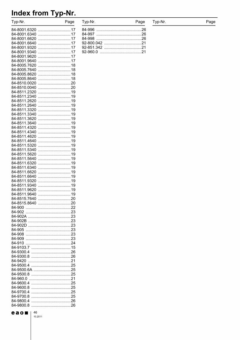
Index from Typ-Nr.
4610.2011
Typ-Nr. Page Typ-Nr. Page Typ-Nr. Page
84-8001.6320 .............................1784-8001.6340 .............................1784-8001.6620 .............................1784-8001.6640 .............................1784-8001.9320 .............................1784-8001.9340 .............................1784-8001.9620 .............................1784-8001.9640 .............................1784-8005.7620 .............................1884-8005.7640 .............................1884-8005.8620 .............................1884-8005.8640 .............................1884-8510.0020 .............................2084-8510.0040 .............................2084-8511.2320 .............................1984-8511.2340 .............................1984-8511.2620 .............................1984-8511.2640 .............................1984-8511.3320 .............................1984-8511.3340 .............................1984-8511.3620 .............................1984-8511.3640 .............................1984-8511.4320 .............................1984-8511.4340 .............................1984-8511.4620 .............................1984-8511.4640 .............................1984-8511.5320 .............................1984-8511.5340 .............................1984-8511.5620 .............................1984-8511.5640 .............................1984-8511.6320 .............................1984-8511.6340 .............................1984-8511.6620 .............................1984-8511.6640 .............................1984-8511.9320 .............................1984-8511.9340 .............................1984-8511.9620 .............................1984-8511.9640 .............................1984-8515.7640 .............................2084-8515.8640 .............................2084-900 ........................................2284-902 ........................................2384-902A ......................................2384-902B ......................................2384-902D ......................................2384-905 ........................................2384-908 ........................................2384-909 ........................................2384-910 ........................................2484-9103.7 ...................................1584-9300.4 ...................................2684-9300.8 ...................................2684-9420 ......................................2184-9500.4 ...................................2584-9500.6A .................................2584-9500.8 ...................................2584-960.0 .....................................2184-9600.4 ...................................2584-9600.8 ...................................2584-9700.4 ...................................2584-9700.8 ...................................2584-9800.4 ...................................2684-9800.8 ...................................26
84-996 ........................................2684-997 ........................................2684-998 ........................................2692-800.042 .................................2192-851.342 .................................2192-960.0 .....................................21


EAO AG Tannwaldstrasse 88 4601 Olten, Switzerland E-mail [email protected] Website www.eao.com Austria Phone +49 201 85 87 0 Fax +49 201 85 87 210 E-mail [email protected] Belgium Phone +32 3 777 82 36 Fax +32 3 777 84 19 E-mail [email protected] China Phone +852 27 86 91 41 Fax +852 27 86 95 61 E-mail [email protected] France Phone +33 1 64 43 37 37 Fax +33 1 64 43 37 49 E-mail [email protected] Germany Phone +49 201 85 87 0 Fax +49 201 85 87 210 E-mail [email protected] Italy Phone +39 035 481 0189 Fax +39 035 481 3786 E-mail [email protected] Japan Phone +81 3 5444 5411 Fax +81 3 5444 0345 E-mail [email protected] Netherlands Phone +31 78 653 17 00 Fax +31 78 653 17 99 E-mail [email protected] Sweden Phone +46 8 683 86 60 Fax +46 8 724 29 12 E-mail [email protected] Switzerland Phone +41 62 388 95 00 Fax +41 62 388 95 55 E-mail [email protected] United Kingdom Phone +44 1444 236 000 Fax +44 1444 236 641 E-mail [email protected] USA Phone +1 203 877 4577 Fax +1 203 877 3694 E-mail [email protected] Other Countries Phone +41 62 286 92 10 Fax +41 62 296 21 62 E-mail [email protected]
EA
O re
serv
es th
e rig
ht to
alte
r sp
ecifi
catio
ns w
ithou
t fur
ther
not
ice


