Embed Size (px)
Citation preview

OPERATINGOPERATINGOPERATINGOPERATINGOPERATINGINSTRUCTIONSINSTRUCTIONSINSTRUCTIONSINSTRUCTIONSINSTRUCTIONS
Plant Water Status Console October 2000
SERIES
SOILMOISTURE EQUIPMENT CORP.P.O. Box 30025, Santa Barbara, CA 93105 U.S.A.Telephone 805-964-3525 - Fax No. 805-683-2189Email: [email protected] - Website: http://www.soilmoisture.com
Fig. 1 - Model 3005 Plant Water Status Console

SOILMOISTURE EQUIPMENT CORP.P.O. Box 30025, Santa Barbara, CA 93105 U.S.A.Telephone 805-964-3525 - Fax No. 805-683-2189Email: [email protected] - Website: http://www.soilmoisture.com
2
Model 3000Model 3000Model 3000Model 3000Model 3000The Plant Water Status Console, Model 3000, is supplied without the compressed gas cylinder orthe pressure regulator, but does come with a 3-foot long, flexible, high pressure (3,000 psi workingpressure) stainless steel connecting hose to connect to your pressure source. One end of the con-necting hose is sealed to the pressure inlet of the console. The other end can be fitting with stan-dard 1/4-inch pipe fittings to connect to your regulated pressure source. We recommend you usebrass pipe and tube fittings that have a 3,000 psi working pressure. The regulated pressure thatyou supply to the console must not exceed the maximum pressure reading of the pressure readoutgauge of the console. For standard units this pressure is 600 psi.
Model 3005 (Fig. 2)Model 3005 (Fig. 2)Model 3005 (Fig. 2)Model 3005 (Fig. 2)Model 3005 (Fig. 2)The Plant Water Status Console, Model 3005, is supplied with a compressed gas cylinder and con-nected pressure regulator for field operation. The pressure regulator has been set at the factory forthe maximum operating pressure of the unit which, for standard units, is 600 psi.
Fig. 2 - Plant Water Status Console (Model 3005 shown)

SOILMOISTURE EQUIPMENT CORP.P.O. Box 30025, Santa Barbara, CA 93105 U.S.A.Telephone 805-964-3525 - Fax No. 805-683-2189Email: [email protected] - Website: http://www.soilmoisture.com
3
Your New Plant Water Status ConsoleYour New Plant Water Status ConsoleYour New Plant Water Status ConsoleYour New Plant Water Status ConsoleYour New Plant Water Status Console
UnpackingUnpackingUnpackingUnpackingUnpacking The Plant Water Status Console was thoroughly tested beforeshipment. When packed, it was in perfect working order. Un-pack with care being sure to remove all packing material. Fol-low the instructions carefully in order to assure long, trouble-free service.
Any damage found upon receipt should be reported immediatelyto the transport carrier for claim. It is important to save theshipping container and all evidence to support your claim. Besure to read all operating instructions thoroughly before operat-ing the unit.
Soilmoisture Equipment Corp. is not responsible for any dam-age, actual or inferred, for misuse or improper handling of thisequipment. The Plant Water Status Console, Model 3000 orModel 3005, is to be used solely as directed by a prudent indi-vidual under normal conditions in the applications intended forthis equipment.
NoteNoteNoteNoteNote
Not Liable ForNot Liable ForNot Liable ForNot Liable ForNot Liable ForImproper UseImproper UseImproper UseImproper UseImproper Use

SOILMOISTURE EQUIPMENT CORP.P.O. Box 30025, Santa Barbara, CA 93105 U.S.A.Telephone 805-964-3525 - Fax No. 805-683-2189Email: [email protected] - Website: http://www.soilmoisture.com
4
ACQUAINT YOURSELF WITH THE PARTSACQUAINT YOURSELF WITH THE PARTSACQUAINT YOURSELF WITH THE PARTSACQUAINT YOURSELF WITH THE PARTSACQUAINT YOURSELF WITH THE PARTS
The four legs screw into the end castings of the control panel.The height is adjustable so the console sits evenly on the bench.Each leg has a knurled lock nut (Fig. 3) to lock the leg at thedesired position. Extension legs are available so that the con-sole can be adjusted to work bench height.
The stainless steel pressure vessel, 2-3/4 inches by 6.5 inchesdeep, will accept a great variety of leaf samples. Very large leafsamples can generally be folded without damage so that thepressure vessel can accommodate them as well.
The specimen holder is held securely in place with four internalcams at the top of the vessel. The vessel’s high pressure gas in-let is in the center of the vessel base. Remove the specimenholder by turning the closing cap counterclockwise 45° andpulling the holder upward (Fig. 5). To insert the specimenholder for a run, turn the specimen holder 45° clockwise to lockit in place.
Fig. 3
Fig. 4

SOILMOISTURE EQUIPMENT CORP.P.O. Box 30025, Santa Barbara, CA 93105 U.S.A.Telephone 805-964-3525 - Fax No. 805-683-2189Email: [email protected] - Website: http://www.soilmoisture.com
5
When the specimen holder is removed the first time, it may re-quire considerable force. The “O” ring used to make the pressureseal tends to “seize” to the metal surface if it is allowed to re-main in the compressed position for a considerable time. Tominimize this problem, apply a thin coat of light grease, such asstopcock grease or Vaseline, to the “O” ring. Then, after thespecimen holder is removed for the first time, it will enter andclose.
The fail safe valve (Fig. 6), in line with the pressure vessel cams,prevents build up of pressure in the pressure vessel unless thespecimen holder is completely locked in place.
Fig. 5
SpecimenHolder
Fail SafeValve
Fig. 6

SOILMOISTURE EQUIPMENT CORP.P.O. Box 30025, Santa Barbara, CA 93105 U.S.A.Telephone 805-964-3525 - Fax No. 805-683-2189Email: [email protected] - Website: http://www.soilmoisture.com
6
The sealing knob (Fig. 7) on the specimen holder actuates thecollet-type closure that pressure seals the specimen and sealingsleeves during a run. Turning the sealing knob clockwise sealsthe specimen. Turning counterclockwise releases the seal.
The 4.5 inch dial face, 1/4% accuracy Test Gauge, graduated inboth psi (pounds per square inch) and in bars, indicates thepressure within the pressure vessel at all times. The swivelsupport base provides a detent to hold the gauge in two readingpositions and one position for transport (see below). A zeropointer position adjusting screw is provided for zeroing thepointer in the event it is jarred out of place.
Transport Position Second Reading PositionFirst Reading Position
SealingKnob
Grommet Support Washer
SpecimenHolder
Sealing SleeveFig. 7
Figs, 8, 9, 10

SOILMOISTURE EQUIPMENT CORP.P.O. Box 30025, Santa Barbara, CA 93105 U.S.A.Telephone 805-964-3525 - Fax No. 805-683-2189Email: [email protected] - Website: http://www.soilmoisture.com
7
The metering valve controls the rate at which pressure is builtup in the pressure vessel. The valve is usually adjusted so thatthe rate of pressure increase is in the range of 5-10 psi per sec-ond. Turning the valve counterclockwise increases the rate offlow. During routine tests, this valve can be left at one fixed po-sition to give uniform pressure building up on all samples.When the metering valve is closed (by turning clockwise) careshould be taken not to exert excessive closing force since thistends to damage the valve seat and the long tapered valvewhich provides the sensitive gas flow control.
The control valve directs the flow of gas into or out of the pres-sure vessel or seals the gas within the pressure vessel (Fig. 11).When the control valve is in the “OFF” position, high pressuregas within the pressure vessel is sealed in and no gas can enteror leave. When the control valve is in the “PRESSURIZE” posi-tion, high pressure supply air from the pressure regulator flowsthrough the metering valve, through the control valve and intothe pressure vessel. When the control valve is in the “EX-HAUST” position, the high pressure gas within the pressurevessel exhausts immediately to the atmosphere.
PR
ES
SU
RIZ
E
OFF
PR
ES
SU
RIZ
E
OFF
EX
HA
US
T
OFF
EX
HA
US
T
Fig. 11

SOILMOISTURE EQUIPMENT CORP.P.O. Box 30025, Santa Barbara, CA 93105 U.S.A.Telephone 805-964-3525 - Fax No. 805-683-2189Email: [email protected] - Website: http://www.soilmoisture.com
8
The hardwood preparation board provides a convenient cuttingblock for the preparation of leaf samples. The notch at the rightend holds the specimen holder during the loading operation tominimize possibilities of damage (Fig. 12).
Underneath the panel a safety relief valve is incorporated inthe system to prevent damage from any excess buildup of pres-sure. The relief valve is set at the factory so that pressure willbe released when it exceeds the maximum operating range ofthe console (Fig. 13).
The pressure regulator is connected to the compressed gas cyl-inder. It can readily be removed for replacement or refilling ofthe cylinder. The output pressure on the regulator has been setat the factory at 600 psi for standard consoles.
SafetyReliefValve
Fig. 12
Fig. 13

SOILMOISTURE EQUIPMENT CORP.P.O. Box 30025, Santa Barbara, CA 93105 U.S.A.Telephone 805-964-3525 - Fax No. 805-683-2189Email: [email protected] - Website: http://www.soilmoisture.com
9
The small pressure gauge screwed into one of the ports of theregulator indicates the pressure within the compressed gas cyl-inder and is used as a guide to indicate when the cylinder needsrefilling (Fig. 14).
The refillable, 2,000 psi, 25 cubic feet capacity, compressed gascylinder is held securely by the bottle bracket beneath the chas-sis. When empty, it can be filled in place without removing itfrom the chassis. The sealing valve at the end of the tank shouldbe kept closed (turn clockwise) except when the console is in use(Fig. 15).
Sealing Valve
PressureRegulator
Toggle LockBracket
Compressed GasCylinder
PressureRegulator
PressureGauge
Fig. 14
Fig. 15

SOILMOISTURE EQUIPMENT CORP.P.O. Box 30025, Santa Barbara, CA 93105 U.S.A.Telephone 805-964-3525 - Fax No. 805-683-2189Email: [email protected] - Website: http://www.soilmoisture.com
10
Step 1.Close the metering valve, turning clockwise (Fig. 16).
Step 2.Turn control valve to “OFF” position (Fig. 17).
Step 3.Open compressed gas cylinder sealing valve, by turning coun-terclockwise (Fig. 18).
Step 4.Remove specimen holder from pressure vessel, as describedearlier, and place in notch of sample preparation board (Fig.19).
Making a RunMaking a RunMaking a RunMaking a RunMaking a Run
SealingValve
Close
Fig. 16
Fig. 17
Fig. 18
Fig. 19

SOILMOISTURE EQUIPMENT CORP.P.O. Box 30025, Santa Barbara, CA 93105 U.S.A.Telephone 805-964-3525 - Fax No. 805-683-2189Email: [email protected] - Website: http://www.soilmoisture.com
11
Step 5.Select sample leaf to run.On initial run to check out unit and to acquaint yourself withits operation, you can substitute a round rod for the leaf samplein order to seal the specimen holder. A nail, rivet, dowel pin, orround 1/8-inch to 1/4 inch in diameter may be used (Fig. 20). Ifthe diameter to be sealed is less than 1/8-inch, select the sup-port washer with the 9/64-inch hole. If the diameter to be sealedis greater than 1/8 inch select the support washer with the 1/4inch hole. Next, select one of the rubber sealing sleeves thatbest fits the stem diameter.
Step 6. Arrange the sealing sleeve on the stem, as shown, andinsert into the specimen holder, as shown. Turn the sealingknob clockwise until the compressing grommet squeezes thesealing sleeve sufficiently around the stem to hold it securely(Fig. 21).
Fig. 21
Fig. 20

SOILMOISTURE EQUIPMENT CORP.P.O. Box 30025, Santa Barbara, CA 93105 U.S.A.Telephone 805-964-3525 - Fax No. 805-683-2189Email: [email protected] - Website: http://www.soilmoisture.com
12
Step 7.Holding the specimen holder by the closing cap, insert the leafsample into the pressure vessel and then push the specimenholder down into place in the pressure vessel. Pushing downwith both thumbs (one thumb on either side of the specimenholder, is a good way to secure the specimen holder in place.)Then, turn the specimen holder 45° clockwise, using the closingcaps to lock it under the cams of the pressure vessel.
Step 8.Tighten the sealing knob further, if necessary, to be sure thatthe sealing sleeve is sealing properly around the stem.
Step 9.Turn the control valve to the PRESSURIZE position (Fig. 22).
Step 10.Slowly open the metering valve, by turning it counterclockwise,and observe the pressure buildup on the readout gauge (Fig.24). Adjust valve until rate of increase is in the range of 5-10 psiper second or at the rate you desire for the test.
Open
Fig. 22
Fig. 23
Fig. 24

SOILMOISTURE EQUIPMENT CORP.P.O. Box 30025, Santa Barbara, CA 93105 U.S.A.Telephone 805-964-3525 - Fax No. 805-683-2189Email: [email protected] - Website: http://www.soilmoisture.com
13
Step 11.To stop the build up of pressure within the vessel at any time,simply turn the control valve to the “OFF” position. To resumebuild up of pressure, turn the control valve slowly to the “Pres-surize” position.
Note: if the control valve is turned quickly to the “PRESSUR-IZE” position after an interruption in pressure build up, asabove, there will be a quick jump in pressure of a few poundswithin the pressure vessel. This is caused by the high pressuregas that builds up in the connecting tube between the meteringvalve and the control valve while the control valve is in the“OFF” position. When the control valve is opened quickly, thissmall volume of high pressure gas (supply pressure -600 psi)discharges immediately into the pressure vessel. Thereafter, themetering valve limits the flow.
Step 12.The build up of pressure within the vessel can also be stopped orreduced at any time by turning the metering valve in a clock-wise direction. Once you know the approximate value for theequilibrium pressure for the plant specimen being tested, it isusually desirable to reduce the rate of pressure build up as youapproach the equilibrium pressure so that the equilibriumvalue can more accurately be determined.
Step 13.As pressure builds up in the pressure vessel, carefully observethe cut end of the petiole of the sample.
If you hear air escaping around the sealing area of the sample,or if the stem seems to be “extruding” or moving up out of thesealing sleeve, simply tighten the sealing knob further to exerthigher sealing pressure to stop the leak or movement.
CAUTION: Never put your eye directly over the center of thepressure vessel during a run. Always observe the sample stemfrom the side. Remember you are dealing with high pressuresand it is possible that a sample - such as an individual needlefrom a pine tree - can be ejected from the holder. It is recom-mended that the end of the cut petiole be observed through alow-power magnifying glass. The glass will give a better viewand also offers protection for the eyes.

SOILMOISTURE EQUIPMENT CORP.P.O. Box 30025, Santa Barbara, CA 93105 U.S.A.Telephone 805-964-3525 - Fax No. 805-683-2189Email: [email protected] - Website: http://www.soilmoisture.com
14
Step 14.The equilibrium pressure for the individual sample is reachedwhen sap starts to flow from the exposed cut end of the sample.
After the sample has been mounted in the extractor and duringthe initial stages of the pressure build up within the extractor,the cut end will appear relatively dry. However, when the equi-librium pressure is reached, the end will slicken up and beshiny and wet in appearance as sap starts to flow from the endof the sample. If pressure is further increased, small bubblesmay be formed and arise in the extruded sap.
The build up of pressure should be stopped immediately whenthe cut end of the sample starts to slicken in appearance by theextrusion of sap. The pressure reading at this point is theequivalent to the negative force with which the plant water isheld within that particular sample. After the equilibrium pres-sure has been reached, one can verify the pressure immediatelyby dropping the pressure in the pressure vessel below the equi-librium value. When this is done, you will note that the sapstops flowing immediately, pulls back into the stem of thesample, and the cut surface acquires the relatively dry appear-ance again. The build up can then be resumed again at a slowrate until sap again begins to flow. You will note that the secondequilibrium obtained matches very closely the first reading.
Fig. 25

SOILMOISTURE EQUIPMENT CORP.P.O. Box 30025, Santa Barbara, CA 93105 U.S.A.Telephone 805-964-3525 - Fax No. 805-683-2189Email: [email protected] - Website: http://www.soilmoisture.com
15
Step 15.After this equilibrium value, sometimes referred to as plant wa-ter potential or plant water stress, has been determined andnoted, pressure in the pressure vessel is exhausted through thecontrol valve by turning it to the “EXHAUST” position.
The exhausting gas will make an appreciable noise dependingupon the pressure in the extraction vessel. The exhaust port isunderneath the control panel (fig. 26) and baffled by the endcastings that hold the leg. The exhausting gas presents no haz-ard to the operator.
Step 16.Remove the sample by loosening the sealing knob slightly whenthe specimen holder is still in the pressure vessel. Then, turnthe closing cap of the specimen holder 1/8 turn (45 °) in a coun-terclockwise direction.
Pull the specimen holder, with the specimen still in place, di-rectly up out of the pressure vessel. Further release the sealingpressure on the specimen by turning the sealing knob counter-clockwise until the specimen and sealing sleeve can be readilyremoved.
The thrust washer will tend to remain in place in the specimenholder and can be left there to accept a subsequent sample.
Step 17.If no further samples are to be run, shut off the compressed gascylinder sealing valve. Remaining high pressure gas within thesystem beyond the storage tank valve can be cleared, if desired,by turning the control valve to the “PRESSURIZE” positionwith the metering valve opened somewhat. Under these condi-tions, the gas in the system beyond the storage tank will ex-
Exhaust Port
Fig. 26

SOILMOISTURE EQUIPMENT CORP.P.O. Box 30025, Santa Barbara, CA 93105 U.S.A.Telephone 805-964-3525 - Fax No. 805-683-2189Email: [email protected] - Website: http://www.soilmoisture.com
16
haust through the pressure vessel. After exhausting the pres-sure, turn the control valve again to the ‘OFF” position.
The compressed gas cylinder can be easily replaced with a fulltank or the tank can be filled from a larger supply tank withoutremoving it from the console.Step 1.Set the console on end (Fig. 27) and support it so that it doesn’tfall over.
Step 2.Loosen and undo the 1-1/8 inch lock nut that holds the tank. A1-1/8 inch open-end wrench or crescent wrench of sufficient sizeis required for this operation. This lock nut has a right-handthread and therefore the nut must be turned in a counterclock-wise direction to undo it.
When the lock nut is completely removed from the storage tankfitting, the pressure regulator will separate from the gas cylin-der and can be left hanging from its stainless steel connectingtube.
GENERAL CARE AND MAINTENANCEGENERAL CARE AND MAINTENANCEGENERAL CARE AND MAINTENANCEGENERAL CARE AND MAINTENANCEGENERAL CARE AND MAINTENANCE
To Replace theTo Replace theTo Replace theTo Replace theTo Replace theCompressed GasCompressed GasCompressed GasCompressed GasCompressed GasCylinderCylinderCylinderCylinderCylinder
Fig. 27
SOILMOISTURE EQUIPMENT CORP.P.O. Box 30025, Santa Barbara, CA 93105 U.S.A.Telephone 805-964-3525 - Fax No. 805-683-2189Email: [email protected] - Website: http://www.soilmoisture.com
17
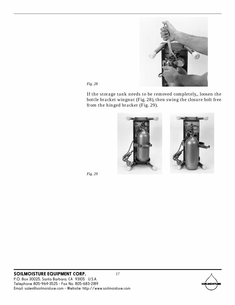
If the storage tank needs to be removed completely,, loosen thebottle bracket wingnut (Fig. 28), then swing the closure bolt freefrom the hinged bracket (Fig. 29).
Fig. 28
Fig. 29

SOILMOISTURE EQUIPMENT CORP.P.O. Box 30025, Santa Barbara, CA 93105 U.S.A.Telephone 805-964-3525 - Fax No. 805-683-2189Email: [email protected] - Website: http://www.soilmoisture.com
18
The compressed gas cylinder can be refilled with gas while it isstill mounted to the console after the regulator has been re-moved (Fig. 30).
If more convenient, the storage tank can be removed from itssupport frame, as indicated on page 17. Filled and then re-placed in the console (Fig. 31).
Flexible, HighPressure Hose
Fig. 30
Fig. 31
To Refill CompressedTo Refill CompressedTo Refill CompressedTo Refill CompressedTo Refill CompressedGas CylinderGas CylinderGas CylinderGas CylinderGas Cylinder

SOILMOISTURE EQUIPMENT CORP.P.O. Box 30025, Santa Barbara, CA 93105 U.S.A.Telephone 805-964-3525 - Fax No. 805-683-2189Email: [email protected] - Website: http://www.soilmoisture.com
19
HorizontalPosition
Fig. 32
To fill the storage tank from a larger supply tank, our Model3070 Flexible, High Pressure Hose is used. Connections for therefilling operation are show on Page 18 (Fig. 31). The lock nutson the ends of the flexible hose are tightened securely in placeon both tanks, using a 1-1/8" open-end wrench or the equivalent.The tank valve on the small storage tank is now opened first.The valve on the larger pressure supply tank is then openedslowly so that the high pressure air from the large tank can flowto the small tank. After a period of time, when no further flownoise of gas is observed, the valve on the large tank is sealedshut. The valve on the smaller tank is then closed securely. Afterthe valves on both tanks are closed, the lock nut on one end ofthe hose is loosened slowly. High pressure gas within the flex-ible hose will drain out of the loosened end. Thereafter, the flex-ible high pressure hose is removed from both tanks. After filling,the pressure regulator is again connected to the compressed gascylinder. The round nose on the connection fitting of the pres-sure regulator makes the pressure seal to the compressed gascylinder. The lock nut serves only to hold this round nose se-curely in contact with the mating fitting on the tank. Thethreads of the lock nuts themselves do not make a pressure seal.Tighten the lock nut securely.
Note: if the compressed gas cylinder has been removed from theconsole, be sure that it is oriented in the proper position so thatthe regulator fits correctly below the console. The pressuregauge on the pressure regulator should be in a horizontal posi-tion when the storage tank is oriented properly.

SOILMOISTURE EQUIPMENT CORP.P.O. Box 30025, Santa Barbara, CA 93105 U.S.A.Telephone 805-964-3525 - Fax No. 805-683-2189Email: [email protected] - Website: http://www.soilmoisture.com
20
Minor AdjustmentsMinor AdjustmentsMinor AdjustmentsMinor AdjustmentsMinor Adjustments
To Adjust the ZeroTo Adjust the ZeroTo Adjust the ZeroTo Adjust the ZeroTo Adjust the ZeroPosition of thePosition of thePosition of thePosition of thePosition of thePressure ReadoutPressure ReadoutPressure ReadoutPressure ReadoutPressure ReadoutGaugeGaugeGaugeGaugeGauge
AdjustingGear
In the event the pointer is jarred off of the zero position duringtransportation and handling, it can be rezeroed easily. To dothis, unscrew the cover plate of the test gauge by turning itcounterclockwise.
The zero adjusting gear (Fig. 33) on the gauge pointer is thenturned clockwise or counterclockwise with the adjusting toolsupplied with the unit to bring the pointer back to the zero posi-tion.
Replace the cover plate by screwing it on in a clockwise posi-tion. Tighten securely to prevent infiltration of dust into thegauge.
Note: on special units the readout pressure gauge is sometimessupplied with a friction-type adjustable pointer. If this type ofgauge is on your unit, the zero position of the pointer is ad-justed by grasping the knurled disc at the center of the pointerand moving the pointer itself with respect to this disc until thedesired zero position is obtained.
Fig. 33

SOILMOISTURE EQUIPMENT CORP.P.O. Box 30025, Santa Barbara, CA 93105 U.S.A.Telephone 805-964-3525 - Fax No. 805-683-2189Email: [email protected] - Website: http://www.soilmoisture.com
21
Replacement PartsReplacement PartsReplacement PartsReplacement PartsReplacement Parts
0761G5 THREE-WAY PRESSURE CONTROL 0.34 kgs
BALL VALVE
0767P2000G1 TANK REGULATOR, 0 to 2000 psi range 1.36 kgs
Replacement for 3005 Tank Regulator
0767P2000G2 SOURCE TANK REGULATOR, for 3000 Plant Water
Status Console, high pressure
0780P0600 TEST GAUGE, 0 to 600 psi, (0 to 40 bars) 0.96 kgs
0780P1500 TEST GAUGE, 0 to 1500 psi, (0 to 100 bars) 0.92 kgs
3000-009L2.25 CONTROL VALVE CONNECTOR, 1/4" NPT 0.09 kgs
3000-011 METERING FLOW CONTROL VALVE 0.28 kgs
3072 COMPRESSED GAS CYLINDER 5.22 kgs
25 cubic ft. capacity nitrogen supply tank.
3075L04CR LEGS, 4" (10 cm) long, (set of 4) 0.41 kgs
3075L08CR LEGS, 8" (20 cm) long, (set of 4) 0.99 kgs
3075L32CR LEGS 32" (81 cm) long, (set of 4) 3.44 kgs
M802X149 NEOPRENE O-RING SEAL, for all specimen holders 0.004 kgs

SOILMOISTURE EQUIPMENT CORP.P.O. Box 30025, Santa Barbara, CA 93105 U.S.A.Telephone 805-964-3525 - Fax No. 805-683-2189Email: [email protected] - Website: http://www.soilmoisture.com
22

SOILMOISTURE EQUIPMENT CORP.P.O. Box 30025, Santa Barbara, CA 93105 U.S.A.Telephone 805-964-3525 - Fax No. 805-683-2189Email: [email protected] - Website: http://www.soilmoisture.com
23

SOILMOISTURE EQUIPMENT CORP.P.O. Box 30025, Santa Barbara, CA 93105 U.S.A.Telephone 805-964-3525 - Fax No. 805-683-2189Email: [email protected] - Website: http://www.soilmoisture.com
24
0898-300/3005.p65 (10/2000)