Embed Size (px)
Citation preview

IOWA MOLD TOOLING CO., INC.
P.O. Box 189Garner, IA 50438Tel: 641.923.3711
Fax: 641.923.2424www.imt.com
Series III Telescopic CranesModels: 6000, 7500 & 8600 22’
Parts & Specifications
Manual # 99906314
Revised: July 15, 2019
Copyright © 2019 Iowa Mold Tooling Co., Inc.All rights reserved
No part of this publication may be reproduced, stored in a retrieval system, or transmitted in any form or by any means, electronic, mechanical, photocopying, recording or otherwise without the prior written permission of Iowa Mold Tooling Co., Inc.
Iowa Mold Tooling Co., Inc. is an Oshkosh Corporation Company

ii
Series III Telescopic Cranes - Manual # 99906314
Operating, servicing and maintaining this vehicle or equipment can expose you to chemicals including engine exhaust, carbon monoxide, phthalates, and lead, which are known to the State of California to cause cancer and birth defects or other reproductive harm. To minimize exposure, avoid breathing exhaust, do not idle the engine except as necessary, service your vehicle or equipment in a well-ventilated area and wear gloves or wash your hands frequently when servicing. For more information go to www.P65Warnings.ca.gov. 70490167
70490167PROP 65BKS 5-29-18
ORANGE , BLACK AND WHITE3.27” 2.70”
CN

iii
Series III Telescopic Cranes - Manual # 99906314
Table of Contents
Section - 1 1
Personal Fall/Tie-Off Protection .....................................................................................................................3
Section - 2 5
6000, 7500, 8600 22’ - Specifications ...........................................................................................................66000, 7500, 8600 22’ - Dimensional Drawings .............................................................................................86000 22’ - Crane Capacity Load Chart...........................................................................................................97500 22’ - Crane Capacity Load Chart.........................................................................................................108600 22’ - Crane Capacity Load Chart......................................................................................................... 11
Section - 3 13
6000, 7500, 8600 22’ - Greasing Instructions ..............................................................................................146000, 7500, 8600 22’ - Greasing Locations .................................................................................................156000, 7500, 8600 22’ - Crane Recommended Spare Parts List ..................................................................166000, 7500, 8600 22’ - Installation Introduction ...........................................................................................176000, 7500 22’ - Crane Installation Kit (99905066).....................................................................................188600 22’ - Crane Installation Kit (99905067)...............................................................................................226000, 7500, 8600 22’ - Chassis Wiring Harness (77441476 / 99905212) ...................................................246000, 7500, 8600 22’ - Telescopic Crane Orientation ..................................................................................25SIII Telescopic Fully Proportional Radio Remote System ............................................................................26SIII Telescopic Single Proportional Radio Remote System .........................................................................27
Section - 4 29
6000, 7500, 8600 22’ - Parts Information .....................................................................................................306000, 7500, 8600 22’ - Crane Assembly Test Stand Mount ........................................................................326000, 7500, 8600 22’ - Crane Assembly Truck Mount ................................................................................346000, 7500, 8600 22’ - Boom Assembly .....................................................................................................366000, 7500, 8600 22’ - Fully Proportional Valve Bank Assembly (99906280) .............................................386000, 7500, 8600 22’ - Single Proportional Valve Bank Assembly (99906279) ...........................................406000, 7500, 8600 22’ - Winch & Anti-Two Block Assembly .........................................................................426000, 7500, 8600 22’ - Crane & Winch Assembly........................................................................................446000, 7500, 8600 22’ - Flip Sheave & Snatch Block Assembly ...................................................................466000, 7500, 8600 22’ - Gear Rotator, Primary (71056543) ..........................................................................486000 22’ - Lower Cylinder (51724528) .........................................................................................................507500 22’ - Lower Cylinder (51723577) .........................................................................................................528600 22’ - Lower Cylinder (51723170) .........................................................................................................546000, 7500, 8600 22’ - Extension Cylinder (51723174) ...............................................................................566000, 7500, 8600 22’ - Planetary Winch - 5500 lb Line (70570761) ............................................................586000, 7500, 8600 22’ - Valve Bank, Fully Proportional (73734727) .............................................................606000, 7500, 8600 22’ - Valve Bank, Single Proportional (73734472) ..........................................................626000, 7500, 8600 22’ - Connection Block Seal Kit For 73734727 (94399213) ............................................646000, 7500, 8600 22’ - Seal Kit for 73734727 (94399214) ..........................................................................666000, 7500, 8600 22’ - Plumbing Diagram, Fully Proportional (99906025) .................................................686000, 7500, 8600 22’ - Plumbing Diagram, Single Proportional (99906026) ...............................................72
Section - 5 75
6000, 7500, 8600 22’ - LED Boom Tip Light Kit (99905289)........................................................................766000, 7500, 8600 22’ - Radio Remote Harness (77441481) .......................................................................786000, 7500, 8600 22’ - Radio Remote Harness (77441481-1) ....................................................................796000, 7500, 8600 22’ - Radio Remote Harness (77441537) .......................................................................806000, 7500, 8600 22’ - Radio Remote Harness (77441537-1) ....................................................................81

iv
Series III Telescopic Cranes - Manual # 99906314
Section - 6 83
6000, 7500, 8600 22’ - Decal Placement .....................................................................................................846000, 7500, 8600 22’ - Thread Torque Charts .............................................................................................866000, 7500, 8600 22’ - Thread Torque Chart - Metric ..................................................................................876000, 7500, 8600 22’ - Turntable Bearing Thread Tightening Sequence .....................................................88

Section - 1 1 Introduction
Series III Telescopic Cranes - Manual # 99906314
Section - 1Introduction

INTRODUCTIONThis volume includes specifications, installation information, and spare parts drawings applicable to your particular crane. For operating, maintenance and repair instructions, see Telescopic Crane Operation, Maintenance, and Repair Manual (IMT part number 99905190).
It is your responsibility to operate and maintain this unit in a manner that will result in the safest working conditions possible. You must be aware of existing Federal, State and Local codes and regulations governing the safe use and maintenance of this IMT crane. The crane was designed and built to meet the standards of ANSI/ASME B30.5, Mobile & Locomotive Cranes. Contact the American Society of Mechanical Engineers (www.asme.org) for more information on ANSI/ASME B30.5.
Misuse of the crane through overloading, abuse, lack of maintenance and unauthorized modifications will void the warranty on any part of the unit subjected to this misuse. No warranty–verbal, written or implied–other than the official, published IMT new machinery and equipment warranty will be valid with this unit.
Throughout the manual, NOTE, CAUTION, and WARNING are used to draw the attention of personnel. They are defined as follows:
WARNINGA WARNING is used when there is the potential
for personal injury or death.
CAUTIONA CAUTION is used when there is the very
strong possibility of damage to the equipment or premature equipment failure.
NOTEA NOTE is used to either convey additional
information or to provide further emphasis for a previous point.
For a safe work environment, treat this equipment with respect and service it regularly.
Series III Telescopic Cranes - Manual # 99906314
2

Section - 1 3 Introduction
Series III Telescopic Cranes - Manual # 99906314
Personal Fall/Tie-Off Protection
When using IMT products for the purpose of personal fall protection, users shall read, understand, and follow the personal fall protection provisions of OSHA 29 CFR 1926.1423, paragraphs (g) Anchorage criteria; (j) Anchoring to the load line; (k) Training. Note OSHA sections, 1926.502(d)(15)* and 1926.502(e)(2)*, are cross-referenced in this section and is up to the user to read, understand, and follow these regulations. The above-referenced provisions within OSHA address specific personal fall protection requirements; however, users of IMT products are required to read, understand and follow all OSHA, industry, workplace, and employer-created regulations governing the use of this product, which includes, but is not limited to, 29 CFR 1926.1423. The user is also required to read, understand, and follow IMT’s warnings and instructions. Nothing within this letter should be interpreted to limit or excuse non-compliance with the above requirements in their entirety.
When using IMT products with personal fall protection as described above, users shall utilize a two-part line with the snatch block installed on the winch load line. The personal fall protection shall be attached to the hook on the snatch block. The personal fall protection device shall be connected to the hook on the snatch block only if the hook has the original safety latch on the hook. At no time shall anyone use the hook on the snatch block for purposes of attaching personal fall protection if the safety latch is not original to the hook, or is missing or damaged, and/or if the safety latch is not properly functioning. At no time shall anyone use the winch wire-rope as a tie-off point for personal fall protection. The failure to follow the above regulations and strict adherence to all applicable OSHA, industry, workplace, employer-created, and IMT warnings and instructions can lead to personal injury or death.
These OSHA regulations can be found at:https://www.osha.gov/pls/oshaweb/owadisp.show_document?p_table=STANDARDS&p_id=67
* In order to use this method, the hook must have a safety latch, the crane must be capable of supporting 5,000 pounds (refer to the load chart affixed to the crane), limit the fall to less than 6-feet, and not allow a swinging fall. Crane hooks should be used only where there is no other suitable anchor point.

This page left intentionally blank
4
Series III Telescopic Cranes - Manual # 99906314

Section - 2 5 Specifications
Series III Telescopic Cranes - Manual # 99906314
Section - 2Specifications

Section - 2 6 Specifications
Series III Telescopic Cranes - Manual # 99906314
6000, 7500, 8600 22’ - Specifications
GENERAL SPECIFICATIONS 6000 7500 8600CRANE RATING* 39,000 ft-lb (5.9 tm) 47,000 ft-lb (6.5 tm) 52,000 ft-lb (7.2 tm)HORIZONTAL REACH-FLIP SHEAVE UP (From Centerline Of Rotation) 22’-6” (6.9 m) 22’-6” (6.9 m) 22’-6” (6.9 m)
HORIZONTAL REACH - FLIP SHEAVE DOWN (From Centerline Of Rotation) 21’ 8” (6.6 m) 21’ 8” (6.6 m) 21’-8” (6.6 m)
FULLY RETRACTED LENGTH 11’-11” (3.6 m) 11’-11” (3.6 m) 11’-11” (3.6 m)
HYDRAULIC EXTENSIONS (2) 60” (152 cm ) 57” (145 cm)
60” (152 cm) 57” (145 cm)
60” (152 cm ) 57” (145 cm)
LIFTING HEIGHT (From Base Of Crane) 23’-10” (7.3 m) 23’-10” (7.3 m) 23’-10” (7.3 m)CRANE WEIGHT 1785 lb (810 kg) 1,795 lb (814 kg) 1,825 lb (828 kg)CRANE STORAGE HEIGHT 40.6” (103 cm) 40.6” (103 cm) 40.6” (103 cm)MOUNTING SPACE REQUIRED (Crane Base)
20” x 21” (50.8 cm x 53.3 cm)
20” x 21” (50.8 cm x 53.3 cm)
20” x 21” (50.8 cm x 53.3 cm)
OPTIMUM PUMP CAPACITY 10 -12 U.S. gpm (37.9 - 45.4 L/min)
10 -12 U.S. gpm (37.9 - 45.4 L/min)
10 -12 U.S. gpm (37.9 - 45.4 L/min)
SYSTEM OPERATING PRESSURE 3200 psi (221 bar) 3200 psi (221 bar) 3200 psi (221 bar)CENTER OF GRAVITY:Horizontal from Centerline of Rotation 42” (106.7 cm) 42” (106.7 cm) 42” (106.7 cm)Vertical from bottom of crane base. 19.6” (49.8 cm) 19.6” (49.8 cm) 19.6” (49.8 cm)
TIE-DOWN BOLT PATTERN (8 bolts) 14.75” x 14.75” (37.5 cm x 37.5 cm)
14.75” x 14.75” (37.5 cm x 37.5 cm)
14.75” x 14.75” (37.5 cm x 37.5 cm)
ROTATIONAL TORQUE 9,000 ft-lb (1.2 tm) 9,000 ft-lb (1.2 tm) 9,000 ft-lb (1.2 tm)ROTATION 400º (22 seconds) 400º (22 seconds) 400º (30 seconds)
LOWER BOOM ELEVATION-10º TO +80º
(12 seconds to raise or lower)
-10º TO +80º (12 seconds to raise or
lower)
-10º TO +80º (12 seconds to raise or
lower)
EXTENSION CYLINDERS (2)60” & 57”
(33 seconds to raise or lower)
60” & 57” (33 seconds to raise or
lower)
60” & 57” (33 seconds to raise or
lower)WINCH SPEED (Single Line) 60 Feet per minute 60 Feet per minute 60 Feet per minuteCHASSIS STYLE Conventional Cab Conventional Cab Conventional Cab
BODY STYLE DOMINATOR™ I or II DOMINATOR™ I or II DOMINATOR™ II (minimum)
CAB-TO-AXLE (1) 60-120” (152-305 cm)
60-120” (152-305 cm)
84-120” (213-305 cm)
RESISTANCE TO BENDING MOMENT 600,000 in-lb 600,000 in-lb 1,200,000 in-lb
RATED MOMENT 52,000 ft-lb (7,190 kg-m)
FRAME SECTION MODULUS- MINIMUM 14.2 cubic inches (232.7 cc)
14.2 cubic inches (232.7 cc)
14.2 cubic inches (232.7 cc)
GROSS VEHICLE WEIGHT RATING (See Note 2)
19,500 lb (8845 kg) minimum (Dominator I
application)26,000 lb (11,793
kg) minimum (Dominator II application)
19,500 lb (8845kg) minimum (Dominator I
application)26,000 lb (11,793 kg)
minimum (Dominator II application)
19,500 lb (8845 kg) minimum (Dominator I
application)26,000 lb (11,793 kg) minimum (Dominator II
application)*Crane rating (ft-lb) is the rated load (lb) multiplied by the respective distance (ft) from centerline of rotation with all extensions retracted and lower boom in horizontal position.

Section - 2 7 Specifications
Series III Telescopic Cranes - Manual # 99906314
6000, 7500, 8600 SPECIFICATIONS (CONTINUED)
POWER SOURCEPTO DRIVEN - Integral mounted hydraulic pump and PTO application. Other standard power sources may be used. Minimum power required is 23.5 horsepower based on 10-12 gpm (37.9 - 45.4 L/min) at 3200 psi (221 bar)
CYLINDER HOLDING VALVESThe holding sides of all cylinders are equipped with integral-mounted counterbalance valves to prevent sudden cylinder collapse in case of hose failure.
ROTATION SYSTEMRotation of the crane is accomplished through a turntable gear bearing powered by a high-torque hydraulic motor through worm gear reduction. Standard rotation is 400º.
HYDRAULIC SYSTEM (PTO DRIVEN) The hydraulic system is an open-centered, full-pressure system that requires 10-12 gpm (37.9 - 45.4 L/min.) optimum oil flow at 3200 psi (221 bar). It is equipped with a four-section, stack-type, electric, remote control valve with an RF remote-control system with a 30’ (9.1 m) radio elimination cable. The system includes a separate hydraulic oil reservoir, suction line filter, return-line filter and control valve.
OVERLOAD PROTECTION SYSTEM Overloading of the crane is prevented by the overload protection system. A pressure transducer mounted on the lower cylinder senses overload conditions. When in an overload situation, the winch-up, extension-out, and boom-down functions are stopped. To relieve the situation, raise the boom, retract the extensions, or lower the winch.
WINCHThe 4,300 lb (1,950 kg) planetary winch is powered using a high-torque hydraulic motor. The lifting capacity of the winch is 4,300 lb (1,950 kg) one-part line. Maximum two-part line capacity is based on the maximum crane capacity. The winch is equipped with 85 ft (25.9 m) of 3/8” (9.5 mm), 6X25 FW PRF RRL IWRC XIPS wire rope. A compact, anti-two block device is included to prevent the lower block or hook assembly from coming in contact with the boom sheave assembly. The winch meets ANSI B30.5 standards.
NOTES:1. The cab to axle (CA) dimension varies based on the configuration of the body, crane, and auxiliary
equipment including welder decks. Make sure the CA is free and clear from obstructions everywhere except between the frame rails.
2. The Gross Vehicle Weight Rating (GVW) is a minimum guideline. Contact IMT if you have questions regarding your particular installation.
3. In addition to these specifications, heavy-duty electrical and cooling systems are required. It is recommended that the vehicle be equipped with an engine tachometer, auxiliary brake lock, and power steering.
4. Weight distribution calculations are required to determine final axle loading.
5. All chassis, crane and body combinations must be stability-tested per ANSI B30.5 requirements.
Iowa Mold Tooling Co., Inc. reserves the right to change specifications and design without notice.

Section - 2 8 Specifications
Series III Telescopic Cranes - Manual # 99906314
6000, 7500, 8600 22’ - Dimensional Drawings
80°
11'-11"(3.6 m)
21'-8"(6.6 m)
14'-3"(4.3 m)
23'-10"(7.3 m)
(Fully
(Fully
retract ed)
extended)
4'-4"(1.3 m)
2'-8"(0.8 m)
(Fully Retracted) (Fully Extended)
Section - 2 9 Specifications
Series III Telescopic Cranes - Manual # 99906314
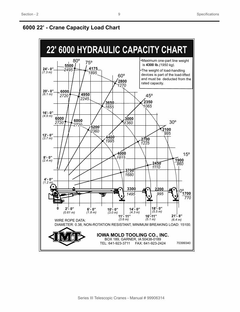
6000 22’ - Crane Capacity Load Chart
70399340
REVISIONS
REV ECO DESCRIPTION DATE BY
70399340
CAPACITY CHART - 6000-22' CRANE
2-24-12IOWA MOLD TOOLING CO., INC
BOX 189, GARNER, IA 50438TEL: 641-923-3711 FAX: 641-923-2424
TECH PUBS GENERATED DRAWING
DRAWN BY
APPROVED BY DATE
DATE SCALETITLE
SIZE DWG NOPAT
A
FULLSHTOF
1 1
NOTES:MATL: .005“ VELVET FINISH LEXAN ADHESIVE: 3M 468 HI-PERFORMANCE APPLIED AFTER SCREENINGSIZE: 5.5” W x 7.5" HCOLORS: BLACK ON WHITE BACKGROUND, AS SHOWNVENDOR: CREATIVE SCREEN PRINT (CRE10) OR EQUIV.
IOWA MOLD TOOLING CO., INC.
22' 6000 HYDRAULIC CAPACITY CHART
TEL: 641-923-3711 FAX: 641-923-2424BOX 189, GARNER, IA 50438-0189
WIRE ROPE DATA: DIAMETER: 0.38, NON-ROTATION RESISTANT, MINIMUM BREAKING LOAD: 15100.
/CN
A 277ADDED WIRE ROPE INFORMATION PER ASME B30-51.1.3 12-12-15 BKS
•Maximum one-part line weight is 4300 lb.(1950 kg).
•The weight of load-handling devices is part of the load-lifted and must be deducted from the rated capacity.
80º 75º
60º
45º
30º
15º
0º
14’- 0”
16’-11” 21’- 8”
0 2’- 0” 10’- 0”6’- 0”(0.61 m) (1.8 m) (3.0 m)
11’- 11”(3.6 m)
(4.3 m)18’- 0”(5.5 m)
(5.1 m) (6.4 m)
16’- 0”
20’- 0”
24’- 0”
4’- 0”(1.2 m)
8’- 0”(2.4 m)
12’- 0”(3.7 m)
(4.9 m)
(6.1 m)
(7.3 m)
B 277-1 DELETED VALUE BOXES 4-29-16 BKS
3300 220017001495 995770
37001680
24501110
19004000
27001225
2100 995
44001995
1815
30001360
23501065
28001270
36501655
52002360
60002720
49502245
41751895
55002495
60002720
60002720
860

Section - 2 10 Specifications
Series III Telescopic Cranes - Manual # 99906314
7500 22’ - Crane Capacity Load Chart
REVISIONS
REV ECO DESCRIPTION DATE BY
70399102
CAPACITY CHART - 7500-22' CRANE
3-29-11IOWA MOLD TOOLING CO., INC
BOX 189, GARNER, IA 50438TEL: 641-923-3711 FAX: 641-923-2424
TECH PUBS GENERATED DRAWING
DRAWN BY
APPROVED BY DATE
DATE SCALETITLE
SIZE DWG NOPAT
A
FULLSHTOF
1 1
NOTES:MATL: .005“ VELVET FINISH LEXAN ADHESIVE: 3M 468 HI-PERFORMANCE APPLIED AFTER SCREENINGSIZE: 5.5” W x 7.5" HCOLORS: BLACK ON WHITE BACKGROUND, AS SHOWNVENDOR: CREATIVE SCREEN PRINT (CRE10) OR EQUIV.
IOWA MOLD TOOLING CO., INC.
22' 7500 HYDRAULIC CAPACITY CHART
TEL: 641-923-3711 FAX: 641-923-2424BOX 189, GARNER, IA 50438-0189
WIRE ROPE DATA: DIAMETER: 0.38, NON-ROTATION RESISTANT, MINIMUM BREAKING LOAD: 15100.
/CNA
277ADDED WIRE ROPE INFORMATION PER ASME B30-51.1.3
12-12-15 BKS
•Maximum one-part line weight is 4300 lb.(1950 kg).
•The weight of load-handling devices is part of the load-lifted and must be deducted from the rated capacity.
80º 75º
60º
45º
30º
15º
0º
11’- 11”
18’- 0”
21’- 8”
0 2’- 0” 10’- 0”6’- 0”(0.61 m) (1.8 m) (3.0 m)
(3.6 m)16’- 11”(5.1 m)
14’- 0”(4.3 m) (5.5 m)
(6.6m)
16’- 0”
20’- 0”
24’- 0”
4’- 0”(1.2 m)
8’- 0”(2.4 m)
12’- 0”(3.7 m)
(4.9 m)
(6.1 m)
(7.3 m)
B
277-1 DELETED VALUE BOXES 4-29-16 BKS
3945 261520451790 1185930
42651935
29001315
22604655
32001450
24351105
53852445
2110
36101635
27251235
36501655
45402060
64802940
75003400
61452785
51502335
67003040
75003400
75003400
1025
70399102
C
11739 21’-8” (6.6 M) WAS 21’-5” (6.5 M)

Section - 2 11 Specifications
Series III Telescopic Cranes - Manual # 99906314
REVISIONS
REV ECO DESCRIPTION DATE BY
70399104
CAPACITY CHART - 8600-22' CRANE
3-30-11IOWA MOLD TOOLING CO., INC
BOX 189, GARNER, IA 50438TEL: 641-923-3711 FAX: 641-923-2424
TECH PUBS GENERATED DRAWING
DRAWN BY
APPROVED BY DATE
DATE SCALETITLE
SIZE DWG NOPAT
A
FULLSHTOF
1 1
NOTES:MATL: .005“ VELVET FINISH LEXAN ADHESIVE: 3M 468 HI-PERFORMANCE APPLIED AFTER SCREENINGSIZE: 5.5” W x 7.5" HCOLORS: BLACK ON WHITE BACKGROUND, AS SHOWNVENDOR: CREATIVE SCREEN PRINT (CRE10) OR EQUIV.
IOWA MOLD TOOLING CO., INC.
22' 8600 HYDRAULIC CAPACITY CHART
TEL: 641-923-3711 FAX: 641-923-2424BOX 189, GARNER, IA 50438-0189
WIRE ROPE DATA: DIAMETER: 0.38, NON-ROTATION RESISTANT, MINIMUM BREAKING LOAD: 15100.
/CNA
277ADDED WIRE ROPE INFORMATION PER ASME B30-51.1.3
12-12-15 BKS
•Maximum one-part line weight is 4300 lb.(1950 kg).
•The weight of load-handling devices is part of the load-lifted and must be deducted from the rated capacity.
80º 75º
60º
45º
30º
15º
0º
11’- 11”
18’- 0”
21’- 8”
0 2’- 0” 10’- 0”6’- 0”(0.61 m) (1.8 m) (3.0 m)
(3.6 m)16’- 11”(5.1 m)
14’- 0”(4.3 m) (5.5 m)
(6.6m)
16’- 0”
20’- 0”
24’- 0”
4’- 0”(1.2 m)
8’- 0”(2.4 m)
12’- 0”(3.7 m)
(4.9 m)
(6.1 m)
(7.3 m)
B
277-1DELETED VALUE BOXES, ADDEDGRIDS 4-29-16 BKS
4325 299521401960 1360970
46752120
32801490
2375
35051590
26201190
55602520
2290
39051770
29351330
37251690
48002175
63952900
86003900
66103000
51952355
67453060
86003900
86003900
1075
70399104
C
11739 21’-8” (6.6 M) WAS 21’-5” (6.5 M) 4-27-12 PAT
5055
8600 22’ - Crane Capacity Load Chart

This page left intentionally blank
12
Series III Telescopic Cranes - Manual # 99906314

Section - 3 13 Crane Reference
Series III Telescopic Cranes - Manual # 99906314
Section - 3Crane Reference

Section - 3 14 Crane Reference
Series III Telescopic Cranes - Manual # 99906314
6000, 7500, 8600 22’ - Greasing Instructions
Different lubricants are required for different sections of your crane. Contact your lubricant supplier for specific product information. Follow the grease and lubricant specifications and intervals listed in this manual for best results.
Crane grease zerks must be greased on a weekly basis during normal operating conditions. Under severe operating conditions the zerks must be greased more frequently. Each grease zerk is marked with a decal, “grease weekly”, as shown. Rotate the worm gear bearing when greasing the worm gear bearing grease zerks.
Crane worm gear bearing teeth must be lubricated weekly with lubriplate gear shield extra-heavy or equivalent, applied with a grease gun, caulk gun or brush. Cover all teeth with grease and leave no exposed metal surfaces showing.
Weekly, remove cover and lubricate withIMT recommended
open-gear compound while rotating crane.IMT part number: 89086246
7039
2399
IOWA MOLD TOOLING CO., INCBOX 189, GARNER, IA 50438
TEL: 515-923-3711 FAX: 515-923-2424
TECH PUBS GENERATED DRAWING
DRAWN BY
APPROVED BY DATE
DATE SCALETITLE
SIZE DWG NO
SHT OF
A
FULL
70392399
BKS 6-13-2018 DECAL-LUBRICATE WORM
NOTES:MATL: .005“ VELVET FINISH LEXANADHESIVE: 3M 468 HI-PERFORMANCE APPLIED AFTER SCREENINGSIZE: 5”W x 1.5”HCOLORS: BLACK ON YELLOW BACKGROUND VENDOR: CREATIVE SCREEN PRINT (CRE10) OR EQUIV.
1 3771 REDRAWN-SAME NO. 7-10-87 FDWAB 9625 REMOVE "WORM" AFTER “LUBRICATE” 12-8-04 PAT SO FITS MORE APPLICATIONSC 12264 MOLUB-ALLOY 936SF TO 882 HEAVY 8-19-14 ADG
--- CHG PROD CODE-REF ECR5679 1-29-96 JT
REVISIONS
REV ECO DESCRIPTION DATE BY
D REMOVED MOLUB-ALLOY 882 HEAVY
CN519 11-22-16 BKS
E CN829 REPLACED PN 89086244WITH 89086246
6-19-18 BKS
ROTATE CRANEWHILE GREASING
TURNTABLEGEAR-BEARING
7039
2524
GREASEWEEKLY
70391612 70391612
GREASEWEEKLY
70391613

Section - 3 15 Crane Reference
Series III Telescopic Cranes - Manual # 99906314
6000, 7500, 8600 22’ - Greasing Locations
LOCATION LUBRICANT APPLICATION METHOD FREQUENCYBase - Turntable Bearing Grease Zerk
Extreme Pressure Lithium grease such as:Shell Alvania 2EPShell Retinax “A”Mobilgrease XHP 462,Cenex ML 365,Xtreme True-Flo EP2Lithium grease or equivalent
Apply with hand or pneumatic pressure grease
gunWeekly
Flip Sheave PinSnatch Block Pin
Worm Gear Bearings Grease Zerks (*Rotate crane while greasing)
Rotation Worm Gear Teeth Molub-Alloy 936 or equivalent Brush or spray on Weekly
Flip
ZerkSheave
Snatch
ZerkBlock
Worm Gear Grease ZerksTurntable
GreaseBearing
Zerk
Opposite Side of Crane
NOTE:
Remove guard. Greaseworm gear teeth withMolub-Alloy 936 orequivalent. Spray orbrush on.
Rotated view

Section - 3 16 Crane Reference
Series III Telescopic Cranes - Manual # 99906314
6000, 7500, 8600 22’ - Crane Recommended Spare Parts List
This parts list is intended to provide the user with parts sufficient to keep the units operating with minimal down-time. Parts not listed are considered not being critical or normal wear items during the first year of operations.
BASE & MASTPART NO. DESCRIPTION QTY.73051919 MOTOR-HYD 101-2638-009 172601949 CAP SCR .50-13X 1.25 SH ZINC 272060177 CAP SCR .62-11X 3.00 HH GR8 Z 19
BOOM ASSEMBLY60030433 WEAR PAD-RC 0.19 X 6.00X 4.00 160030339 WEAR PAD-RND 0.19X 2.00X .60X .81 260030432 WEAR PAD-RC 0.25 X 6.00X 5.00 160030431 WEAR PAD-RC 0.25X 6.00X 1.25 460030425 WEAR PAD-RND 0.44X 1.25X .50X .50 260030427 WEAR PAD-RND 0.19X 2.00X 1.25X .44 4
ANTI-TWO-BLOCK ASSEMBLY77041863 LIMIT SWITCH 1
CRANE & WINCH ASSEMBLY52719629 PIN-TYPE MM 1.50X 9.75 ( 9.19) 252723197 PIN-TYPE MM 1.50X 9.75 ( 9.19) 160140913 PIN-PIN-TYPE NN 1.50X 7.25 TYPE NN 1.50X 7.25 160140914 PIN-TYPE NN 1.50X10.75 270735099 HOOK-SWVL POS LOCK BBRG 5TON 170580182 WIRE ROPE ASM-.38(6X25)X85’ FW IWRC XIPS 160030134 SHEAVE- 8.00 POLYMER 1
LOWER CYLINDER (51723170 - 8600) (51723577 - 7500) (51724528 - 6000)94399128 SEAL KIT - 8600 194399127 SEAL KIT - 7500 194399356 SEAL KIT - 6000
EXTENSION CYLINDER (51723174)94399126 SEAL KIT 1
WINCH (70570761)SEAL KITMOTORCOUNTERBALANCE VALVE
VALVE BANK (73734635)94399213 SEAL KIT, CONNECTION BLOCK 194399214 SEAL KIT, VALVE SECTIONS 177041898 SOLENOID, 12V 1

Section - 3 17 Crane Reference
Series III Telescopic Cranes - Manual # 99906314
6000, 7500, 8600 22’ - Installation Introduction
GENERAL
This section contains instructions for the installation of your crane. Prior to installing the crane and hy-draulic components, make sure the chassis is ready to receive the crane (see Installation Section of the IMT Telescopic Crane Operation & Safety Manual, 99905190).
Reinforce the chassis frame, as necessary, and install the PTO and pump.
Each installation may vary in components used. It is important to use hoses of proper length, pumps of correct size, and PTO’s of adequate speed. Study the applicable installation kit in the parts section before attempting any installation.
CRANE INSTALLATION
In addition to meeting minimum chassis specifications, there must be sufficient room to mount the crane and the platform must be strong enough to support the crane and rated load. Install the crane only on an IMT designed and approved truck body. The body must be designed to sustain the forces imposed by the crane when lifting the full rated load. In addition, an IMT body is designed to take full advantage of the standard reservoir placement. This reservoir is installed in the cargo area of the body. Before attempting to install the crane, the body must be installed on the chassis.

Section - 3 18 Crane Reference
Series III Telescopic Cranes - Manual # 99906314
6000, 7500 22’ - Crane Installation Kit (99905066)
SECTION E-ESCALE 0.13 : 1
�
�
� �
26
8
LEVEL INDICATOR TO BE INSTALLEDPARALLEL TO DOOR REINFORCEMENTS
USE CUT WASHERS WHERE NEEDEDTO CLEAR CRANE COMPARTMENT STRUCTURE.

Section - 3 19 Crane Reference
Series III Telescopic Cranes - Manual # 99906314
99905066 PARTS LIST
ITEM NO. PART NO. DESCRIPTION QTY.1. BODY DOM S3 REF2. 72063066 WASHER 1.00 FLAT HI STR AR3. 72042097 LEVEL INDICATOR LEVEL 14. 52720014 RISER-6025 CRANE BASE 11in DOM 2 REF5. 93713668 INSTL-KIT SERIES III 7500-8600S 16. 72602151 CAP SCR 1.00- 8X 2.50 SH PLAIN AR7. 72062152 CAP SCR 1.00- 8X 3.50 SH PLAIN AR8. 72063286 WASHER-FLAT 1.00 H ASTM F436 Z-CUT ARREV. E
NOTE:The 2.5” Bolts supplied are part of the crane installation kit. Determine the Crane box top plate thickness prior to mounting. If different length bolts Are required, they must be 1-8, grade 8, zinc coated, of proper length.Failure to use proper length bolts may cause the bolts under the crane Swing bearing to bottom out before torquing. Insure a minimun of 1-1/2” Thread engagement.

Section - 3 20 Crane Reference
Series III Telescopic Cranes - Manual # 99906314
99905066-1, CRANE INSTALLATION KIT, CONTINUED
SECTION G-GSCALE 0.13 : 1
�
�
7
2
2
6 USING TIE DOWN BOLTS FROM CRANE INSTALL KIT,BOLT RISER TO BOTTOM OF CRANE BASE.THEN LOCATE CRANE WITH RISER ONTO BODY.
CAP SCREW PASSES UPWARD THROUGH WASHER,CRANE COMPARTMENT TOP, AND INTO CRANE RISER.REFER TO CRANE MANUAL FOR SPECIFIC TORQUE REQUIREMENTS.
Section - 3 21 Crane Reference
Series III Telescopic Cranes - Manual # 99906314
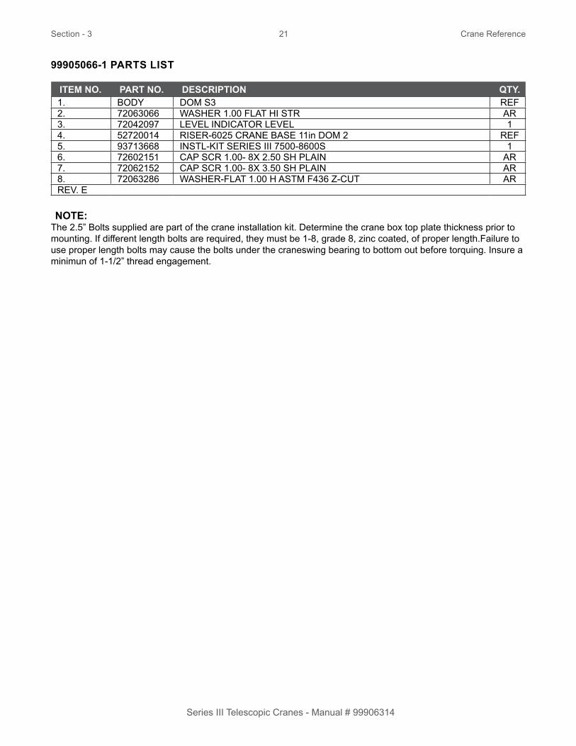
99905066-1 PARTS LIST
ITEM NO. PART NO. DESCRIPTION QTY.1. BODY DOM S3 REF2. 72063066 WASHER 1.00 FLAT HI STR AR3. 72042097 LEVEL INDICATOR LEVEL 14. 52720014 RISER-6025 CRANE BASE 11in DOM 2 REF5. 93713668 INSTL-KIT SERIES III 7500-8600S 16. 72602151 CAP SCR 1.00- 8X 2.50 SH PLAIN AR7. 72062152 CAP SCR 1.00- 8X 3.50 SH PLAIN AR8. 72063286 WASHER-FLAT 1.00 H ASTM F436 Z-CUT ARREV. E
NOTE:The 2.5” Bolts supplied are part of the crane installation kit. Determine the crane box top plate thickness prior to mounting. If different length bolts are required, they must be 1-8, grade 8, zinc coated, of proper length.Failure to use proper length bolts may cause the bolts under the craneswing bearing to bottom out before torquing. Insure a minimun of 1-1/2” thread engagement.

Section - 3 22 Crane Reference
Series III Telescopic Cranes - Manual # 99906314
8600 22’ - Crane Installation Kit (99905067)
SECTION E-ESCALE 0.13 : 1
SECTION J-JSCALE 0.26 : 1
E
E
J J
LEVEL INDICATOR TO BE INSTALLED PARALLEL TO DOOR REINFORCEMENTS
1
5
7 USE CUT WASHERS WHERE NEEDEDTO CLEAR CRANE COMPARTMENT STRUCTURE.
2

Section - 3 23 Crane Reference
Series III Telescopic Cranes - Manual # 99906314
99905067 PARTS LIST
ITEM NO. PART NO. DESCRIPTION QTY.1 72063066 WASHER 1.00 FLAT HI STR AR2 72042097 LEVEL INDICATOR LEVEL 13 52720014 RISER-6025 CRANE BASE 11in DOM 2 REF4 93713669 INSTL-KIT DS3 -DOM 2 8600S-10000 15 72602151 CAP SCR 1.00- 8X 2.50 SH PLAIN AR6 72602152 CAP SCR 1.00- 8X 3.50 SH PLAIN AR7 72063286 WASHER-FLAT 1.00 H ASTM F436 Z-CUT ARREV. H CN963
NOTES:The 2.5” Bolts supplied are part of the crane installation kit. Determine the crane box top plate thickness prior to mounting. If different length bolts are required, they must be 1-8, grade 8, zinc coated, of proper length. Failure to use proper length bolts may cause the bolts under the crane swing bearing to bottom out before torquing. Insure a minimun of 1-1/2” thread engagement.
SECTION G-GSCALE 0.13 : 1
G
G
6
1
1
5 USING TIE DOWN BOLTS FROM CRANE INSTALL KIT,BOLT RISER TO BOTTOM OF CRANE BASE.THEN LOCATE CRANE WITH RISER ONTO BODY.
CAP SCREW PASSES UPWARD THROUGH WASHER,CRANE COMPARTMENT TOP, AND INTO CRANE RISER.REFER TO CRANE MANUAL FOR SPECIFIC TORQUE REQUIREMENTS.
3

Section - 3 24 Crane Reference
Series III Telescopic Cranes - Manual # 99906314
6000, 7500, 8600 22’ - Chassis Wiring Harness (77441476 / 99905212)
ADDITIONAL INSTALLATION COMPONENTS, NON-IMT BODY (93713748)Boom Flood Lights
Crane Hour Meter
EngineSpeed
Ground
Engine Stop
SelectorSolenoid
To RecommendedSelector Solenoid
IMT Harness(77441476)
12 Volt Normally Closed Output From Boom Stow Sensor
12 Volt Normally OpenOutput From Boom Stow Sensor
Stow Signal Power
To 12 Volt Source For BoomStow Sensor Power
In-Line 5A Fuse
Compressor On
To Recommended Compressor on(12V Latching Signal)
To Recommended OEM 12VEngine Start (12V Momentary Signal)
Engine Start
Power
In-Line 15A Fuse To 12V IgnitionKeyed Power
RecommendedUsing PTOGround Signal
To 12V BatterySource
87A8786
3085
To Recommended Engine Kill Option
3085
87A8786
To Battery Ground
To Recommended OEM 12V Speed Control
To Recommended 12V Crane Hour Meter(12V Latching Signal When Link Is Established Between the Radio and Transmitter)
To Recommended Switch12V Power (Not To Exceed7 AMPS) Horn
Circuit
8630 87
85
87a
8630 87
85
87aHORN OUTPUT (2)
HORN OUTPUT (1)
SEE NOTE
STOW SENSOR CN (IMT CHASSIS HARNESS)
STOW SENSOR NO (IMT CHASSIS HARNESS)
GRAY CONNECTOR ON RADIO (PIN 10)GRAY CONNECTOR ON RADIO (PIN 9)
HORN CIRCUIT
NOTE: This may be 12V or ground. Please make sure to see how horn functions before wiring in IMT horn circuit.

Section - 3 25 Crane Reference
Series III Telescopic Cranes - Manual # 99906314
6000, 7500, 8600 22’ - Telescopic Crane Orientation
When an IMT telescopic crane is not factory-installed on a body, the crane is packed with the boom oriented as it is built on a test stand to facilitate handling. Install the crane on the body with boom pointing backward. Once the crane is bolted down, it can be rotated 180° to the boom rest.
With non-factory-installed cranes, a loose hose sleeve is included in the box with the installation kit. After the crane is installed, rotated and placed in the boom support, wrap the hose sleeve around the hoses, then slide sleeve toward the fittings to protect the hoses during rotation.
400°ROTATION
OUTLINE OFTRUCK BODY
REAR OFTRUCK
BOOMREST
Sleeve 60350105
Viewed looking up from crane box. The pressure, return, androtation hoses are wrapped in the 60350105 hose sleeve.

Section - 3 26 Crane Reference
Series III Telescopic Cranes - Manual # 99906314
SIII Telescopic Fully Proportional Radio Remote System
IMT telescopic cranes are controlled by radio remote controls. See, Telescopic Fully Proportional Crane Radio Remote System Manual, IMT part number 99906209, for complete details.
QTY. PART NO. DESCRIPTION1. 70734957 TRANSM-RAD REM TELE S3 FP NON-G FHSS 2401. 70734958 TRANSM-RAD REM TELE S3 FP GATED FHSS 2411. 70734960 RECEIVER-RAD REM TELE S3 FP FHSS 2400
RECEIVER
REMOTE

Section - 3 27 Crane Reference
Series III Telescopic Cranes - Manual # 99906314
SIII Telescopic Single Proportional Radio Remote System
IMT telescopic cranes are controlled by radio remote controls. See the Series III Telescopic Single Proportional Radio Remote System, IMT part number 99906210, for complete details.
QTY. PART NO. DESCRIPTION1. 70734956 TRANSM-RAD REM TELE S3 SP & EM FHSS 24001. 70735093 TRANSM-RAD S3 SP EM 5LED FHSS 2400
REMOTE RECEIVER
70735094
' . . .) ' i '
.
•
'
.. ;i:'_-,f. ,-·'_ ' ·, .. ,,
• • '
ccw
cw
AIR 90 . ON I OFF
{) ®®• A&oe
2oe %LOAD RPM Hi/Lo
IN DOWN
OUT UP EXTEND WINCH
Made In U.S.A .
�
ENGINE HORN TX ON
STOPf TX OFF
DOWN
UP BOOM
�
�
' '
'
' -.. , . ' -- ,_ • .. -� . _, . --· ... , . ' . . . . '
,,
•
7073
5093
W
SMB
-965
3

This page left intentionally blank
28
Series III Telescopic Cranes - Manual # 99906314

Section - 4 29 Parts
Series III Telescopic Cranes - Manual # 99906314
Section - 4Parts

Section - 4 30 Parts
Series III Telescopic Cranes - Manual # 99906314
6000, 7500, 8600 22’ - Parts Information
GENERAL
This section contains the exploded parts drawings and accompanying parts lists for the assemblies used on this crane. These drawings are intended to be used in conjunction with the instructions found in the maintenance and repair manuals for this crane family. For optional equipment such as winches and remote controls, refer to the appropriate service manual.
CRANE IDENTIFICATION
Every IMT crane has an identification placard (see figure below). This placard is attached to the inner boom, mast, or crane base. When ordering parts, communicating warranty information, or referring to the unit in correspondence, always include the serial number and model numbers. Address all inquiries to your authorized IMT distributor or to:
Iowa Mold Tooling Co., Inc. Box 189, Garner, IA 50438-0189 Telephone: 800-554-4421
WARNINGDo not attempt to repair any component
without reading the information contained in the repair section. Pay particular attentionto statements marked Warning, Caution orNote in that section. Failure to comply with these instructions may result in damage tothe equipment, personal injury or death.
MODELNUMBER
SERIALNUMBER
MFGDATE
IOWA MOLD TOOLING CO., INC.BOX 189, GARNER, IA 50438-0189

Section - 4 31 Parts
Series III Telescopic Cranes - Manual # 99906314
CYLINDER IDENTIFICATION
To insure proper replacement parts are received, it is necessary to specify the complete number/letter sequence for any part requested. Part numbers may be cross checked by comparing the stamped identification on the cylinder case (See figure below) against the information contained in the service manual. You must include the part number stamped on the cylinder case when ordering parts.
WELDMENT IDENTIFICATION
Each of the major weldments– base, mast, inner boom, outer boom, extension boom, and stabilizer weldments–bear a stamped part number. Any time a major weldment is replaced, you must specify the complete part number as stamped on the weldment. The locations of the part numbers are shown in the Crane Reference Section.
ORDERING REPAIR PARTS
When ordering replacement parts:
1. Give the model number of the unit.
2. Give the serial number of the unit.
3. Specify the complete part number. When ordering cylinder parts, or one of the main weldments, always give the stamped part number.
4. Give a complete description of the part
5. Specify the quantity required.
CYLINDERPART NUMBER
LOCATION

Section - 4 32 Parts
Series III Telescopic Cranes - Manual # 99906314
6000, 7500, 8600 22’ - Crane Assembly Test Stand Mount (99904970)
59
53
60
11
34
34
2928
45
96
109
96
54
10970
70
100 7273
70
TORQUE TO 160 FT LB
4 PLCS
11 PLCS
SEE NOTE #1
SEE NOTE #1
SEE NOTES #1 & #3
PORT B
PORT A
SEE NOTE #2
SEE NOTE #2
5353 53 53
PORT A PORT B
TOP VIEWCUT WASHER LOCATION
BOTTOM VIEWPORT IDENTIFICATION
46

Section - 4 33 Parts
Series III Telescopic Cranes - Manual # 99906314
99904970 PARTS LIST
ITEM NO. PART NO. DESCRIPTION KIT NO. QTY.11. 52725122 MAST WLDMNT-SERIES III S 128. 60120138 SLIDE-ROTATION STOP 3816 129. 60128849 GEAR GUARD 6025 SII 134. 70029595 THREADED PLUG 1.00-8 (3816) 245. 71056543 GEAR ROTATOR 5020 170-00012-1 146. 76039295 GASKET-GEA19 008-10056-1 45 148. 71414204 PLATE-SINGLE SHEAVE (20#) .38 WIRE ROPE 153. 72063216 WASHER .62 N FLAT-CUT 3816 454. 73051919 MOTOR-HYD (101-2638-009) 159. 72060177 CAP SCR .62-11X 3.00 HH GR8 Z 1 1560. 72063119 WASHER .62 FLAT ASTM F436 1 1170. 70034382 CAP-GREASE PRO20 GC-RED 5 672. 72053301 COUPLING-GLV .12 SCH 40 5 173. 72053508 ZERK-NPT .12 5 496. 72601949 CAP SCR .50-13X 1.25 SH ZC 5 2100. 51395121 HOSE-AA .13 X 13.50 OAL (2-2) 5 1109. 72533613 ADPTR-M STR/M JIC 10 6 6 2REV. AK
NOTES:1. Use rust preventative on slide stop, bearing race, bottom of mast , and top of gear bearing.
2. Apply blue thread locker.
3. Apply gear lube on gear teeth.
4. Base and mast assembly shown as mounted on test stand.
Section - 4 34 Parts
Series III Telescopic Cranes - Manual # 99906314
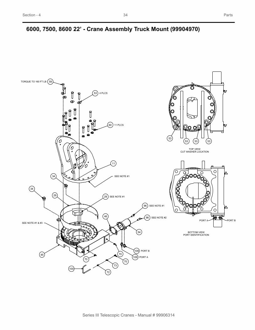
6000, 7500, 8600 22’ - Crane Assembly Truck Mount (99904970)
59
53
60
4 PLCS
11 PLCS
11
34
34
29 28
45
70
70109
109
46
96
96
54
7073
72100
SEE NOTE #1
SEE NOTE #1
SEE NOTE #1 & #3
SEE NOTE #2
SEE NOTE #1
PORT B
PORT A
5353 53 53
TOP VIEWCUT WASHER LOCATION
BOTTOM VIEWPORT IDENTIFICATION
PORT A PORT B
TORQUE TO 160 FT LB

Section - 4 35 Parts
Series III Telescopic Cranes - Manual # 99906314
99904970 PARTS LIST
ITEM NO. PART NO. DESCRIPTION KIT NO. QTY.11. 52725122 MAST WLDMNT-SERIES III S 128. 60120138 SLIDE-ROTATION STOP 3816 129. 60128849 GEAR GUARD 6025 SII 134. 70029595 THREADED PLUG 1.00-8 (3816) 245. 71056543 GEAR ROTATOR 5020 170-00012-1 146. 76039295 GASKET-GEA19 008-10056-1 45 153. 72063216 WASHER .62 N FLAT-CUT 3816 454. 73051919 MOTOR-HYD (101-2638-009) 159. 72060177 CAP SCR .62-11X 3.00 HH GR8 Z 1 1560. 72063119 WASHER .62 FLAT ASTM F436 1 1170. 70034382 CAP-GREASE PRO20 GC-RED 5 672. 72053301 COUPLING-GLV .12 SCH 40 5 173. 72053508 ZERK-NPT .12 5 496. 72601949 CAP SCR .50-13X 1.25 SH ZC 5 2100. 51395121 HOSE-AA .13 X 13.50 (2-2) 5 1109. 72533613 ADPTR-M STR/M JIC 10 6 6 2REV. AK
NOTES:1. Use rust preventative on slide stop, bearing race, bottom of mast , and top of gear bearing.
2. Apply blue thread locker.
3. Apply gear lube on gear teeth.
4. Base and mast assembly shown as mounted on truck.
Section - 4 36 Parts
Series III Telescopic Cranes - Manual # 99906314
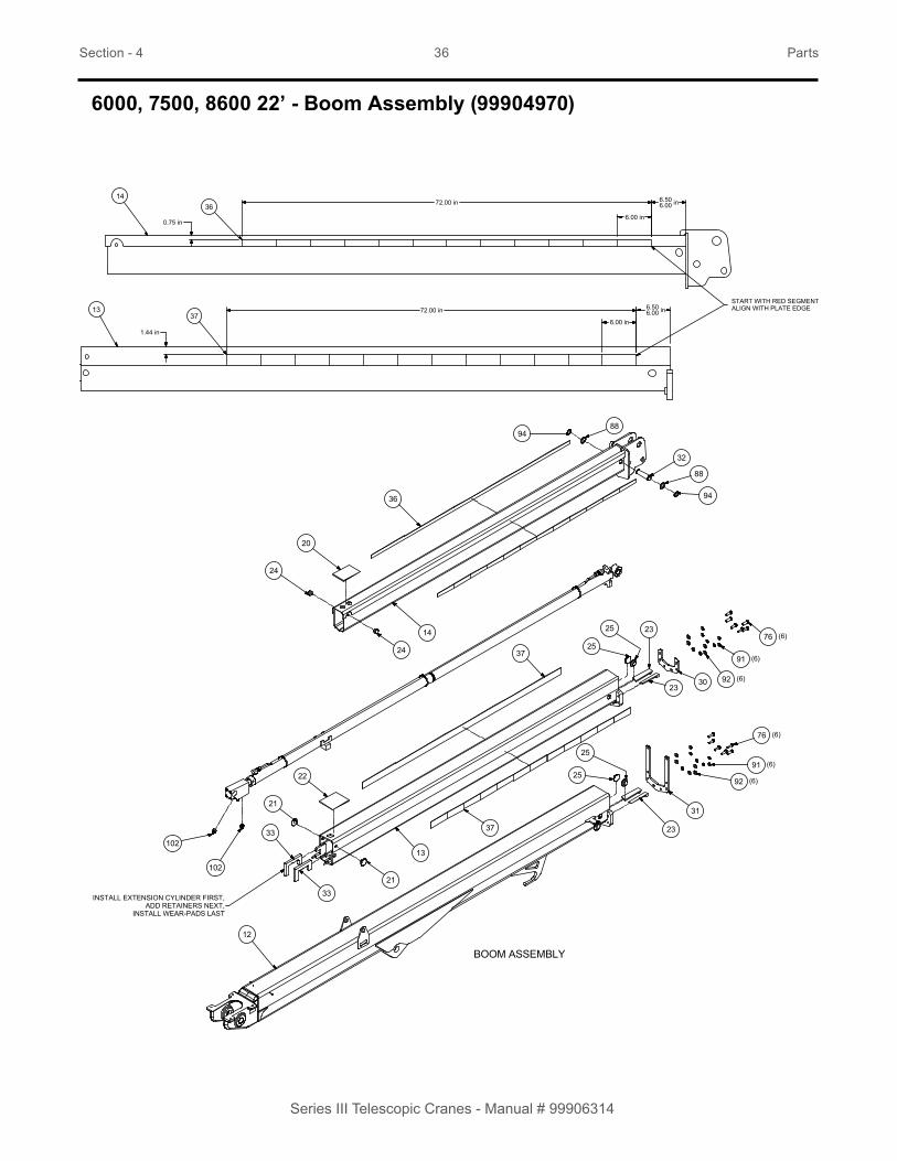
6000, 7500, 8600 22’ - Boom Assembly (99904970)
BOOM ASSEMBLY
INSTALL EXTENSION CYLINDER FIRST,ADD RETAINERS NEXT,
INSTALL WEAR-PADS LAST
102
102
24
20
36
9488
32
88
94
3023
23
25
25
37
13
37
21
22
21
33
33
12
23
25
25
14
24
76
91
92
76
91
92
31
(6)
(6)
(6)
(6)
(6)
(6)
36
37
14
13
6.506.00 in
6.00 in
72.00 in
6.506.00 in72.00 in
6.00 in
START WITH RED SEGMENT ALIGN WITH PLATE EDGE
0.75 in
1.44 in

Section - 4 37 Parts
Series III Telescopic Cranes - Manual # 99906314
99904970 PARTS LIST
ITEM NO. PART NO. DESCRIPTION KIT NO. QTY.12. 52725158 WLDMNT-LOWER BOOM 113. 52725159 WLDMNT-1st STAGE EXT BOOM 114. 52723169 WLDMNT-2ND STAGE EXT BOOM 120. 60030433 WEAR PAD-RC 0.19 X 6.00X 4.00 121. 60030339 WEAR PAD-RND 0.19X 2.00X .60X .81 222. 60030432 WEAR PAD-RC 0.25 X 6.00X 5.00 123. 60030431 WEAR PAD-RC 0.25X 6.00X 1.25 424. 60030425 WEAR PAD-RND 0.44X 1.25X .50X .50 225. 60030427 WEAR PAD-RND 0.19X 2.00X 1.25X .44 430. 60136129 CAP-FIRST STAGE 131. 60140900 CAP-LOWER BOOM 111 132. 60136309 PIN-TYPE A 1.25X 4.27 (3.83) 133. 60127979 PLATE-EXT CYL C-CLIP 236. 70399053 TAPE-REFLECTIVE RED/SILVER 1.25X72.00 237. 70396734 TAPE-REFLECTIVE RED/SILVER 2.00X72.00 238. 70580182 CABLE ASM-1020in .38 6X25 FW IWRC XIPS 176. 72060093 CAP SCR .50-13X 1.50 HH GR5 Z 5 1588. 72063035 MACHY BUSHING 1.25X10 GA NR 5 291. 72063053 WASHER .50 LOCK 5 1592. 72063132 WASHER .50 FLAT ASTM F436 5 1794. 72066129 RETAINING RING-EXT 1.25 HD 5 2102. 72532356 ADPTR-M STR/M JIC 8 6 6 6REV. AK
NOTES: 1. Cylinder cap & cap screws are included with the extension cylinder.
2. Use blue thread locker.

Section - 4 38 Parts
Series III Telescopic Cranes - Manual # 99906314
6000, 7500, 8600 22’ - Fully Proportional Valve Bank Assembly (99906280)
8
4
8
5
6
8
5
85
7
20
17
16
12
3
2
9
10
11
12
3
2
13
1
14
15
19
18
21
NOTE ORIENTATION OF GAUGE

Section - 4 39 Parts
Series III Telescopic Cranes - Manual # 99906314
99906280 PARTS LIST
ITEM NO. PART NO. DESCRIPTION QTY1. 73734727 VALVE BANK-4-SECT PSL2 W OC INLT 12. 72602052 CAP SCR M 8-1.25X 16 HHZ 43. 72601797 WASHER-LOCK 8MM 44. 72533583 ELBOW-M STR/45/M JIC 8 6 15. 72532358 ADPTR-M STR/M JIC 8 8 36. 72532670 ELBOW-M JIC/45/F JIC 8 8 17. 72532361 ADPTR-M STR/M JIC 8 10 18. 72532356 ADPTR-M STR/M JIC 8 6 49. 72063186 WASHER .38 FLAT 410. 72063051 WASHER .38 LOCK 411. 72060044 CAP SCR .38-16X .75 HH GR5 Z 412. 72602065 WASHER-FLAT M 8 413. 60140839 BRKT-MAST VB 6000-8600S 114. 60143075 BRKT-MAST VB 6000-8600S FP 115. 73052156 FILTER-PRES 4000PSI 25GPM 10MIC -12 116. 72534898 O-RING EXTENDER 08-08 117. 72533623 ELBOW-M STR/90/M JIC 8 12 118. 72053767 ELBOW-M STR/90/M JIC 12 12 119. 71415690 TUBE ASM-PRESSURE FILTER S3FP SMALL MAST 120. 72532686 PLUG-STR SOC HD STL 8 ( .75 THD) 121. 73050225 GAUGE-5000 PSI 2.5IN CB MOUNT -4 MORB 1Rev. Initial Release

Section - 4 40 Parts
Series III Telescopic Cranes - Manual # 99906314
6000, 7500, 8600 22’ - Single Proportional Valve Bank Assembly (99906279)
43
4
3
5
5
6
6
6
6
3
4
3
4
89
7
1
2
NOTE ORIENTATION OF GAUGE

Section - 4 41 Parts
Series III Telescopic Cranes - Manual # 99906314
99906279 PARTS LIST
ITEM NO PART NO. DESCRIPTION QTY.1. 72533583 ELBOW-M STR/45/M JIC 8 6 12. 72532670 ELBOW-M JIC/45/F JIC 8 8 13. 72063001 WASHER .25 FLAT 44. 72062104 NUT .25-20 HEX NYLOCK 45. 60140839 BRKT-MAST VB 6000-8600S 26. 72060004 CAP SCR .25-20X 1.00 HH GR5 Z 47. 73734472 VALVE BANK-MOD.INLET (PW) 12VDC IP69 18. 72534847 ADPTR-M JIC/F JIC 8 8 DIAGNOSTIC TEE 19. 73050225 GAUGE-5000 PSI 2.5IN CB MOUNT -4 MORB 1Rev. Initial Release

Section - 4 42 Parts
Series III Telescopic Cranes - Manual # 99906314
6000, 7500, 8600 22’ - Winch & Anti-Two Block Assembly
WINCH ASSEMBLY
A2B ASSEMBLY
105105 PORT APORT B
9771
95
81
93
78
57
50133
93
132
APPLY BLUE LOCTITE
81
SEE NOTE 1

Section - 4 43 Parts
Series III Telescopic Cranes - Manual # 99906314
PARTS LIST
ITEM NO. PART NO. DESCRIPTION KIT NO. QTY.50. 72034485 CLAMP-PLASTIC 1/4” CABLE 857. 77041863 SWITCH-LIMIT DT04-4P CONN 171. 71413185 SPRING-.105WIRE 0.75OD 2.875 LG 5 178. 72060639 SCR-MACH 10-24X 1.25 RDH 5 281. 72062093 NUT # 8-32 HEX ZINC 5 293. 72063271 WASHER # 8 W FLAT ANSI B27.2Z 5 295. 72601938 BOLT-EYE # 8-32X 1.125 5 197. 72602085 BOLT-SHLDR .38X 1.25 (5/16 thds) SS 5 1105. 72532359 ADPTR-M STR/M JIC 10 8 6 2132. 72062207 NUT 8-32 HEX NYLOCK 1133. 72034572 CLAMP-PLASTIC .38 CABLE 1REV. AK
NOTES: No flood lights use part number, 72034485, clamp-plastic .25 cable. With flood lights use part number, 72034572, clamp-plastic .38 cable.

Section - 4 44 Parts
Series III Telescopic Cranes - Manual # 99906314
6000, 7500, 8600 22’ - Crane & Winch Assembly
7691
118
117
49
61
62
63
52
51
102
51
52
102
103
101
9
119
118
9176
119118
91
76
112
7590
86
86
90 75
114 85 85 83
114858583
SEE NOTE #2
SEE NOTE #2
SEE NOTE #2
SEE NOTE #2
SEE NOTE #1
SEE NOTE #1
APPLY BLUE LOCTITE
8690 75
125126
127
129
128
130
113

Section - 4 45 Parts
Series III Telescopic Cranes - Manual # 99906314
PARTS LIST
ITEM NO. PART NO. DESCRIPTION KIT NO. QTY.9. 51723170 CYL-4.50/2.2 25.06S 45.52CC C /PD8 (8500 ONLY) 1
51723577 CYL-4.25/2.2 25.06S 45.52CC C (7500 ONLY) 151724528 CYL-4.0/2.2 25.06S 45.52CC C /PD (6000 ONLY) 1
49. 70570761 WINCH-PLANETARY 5500 LB LINE PULL 151. 72063036 MACHY BUSHING 1.50X14 GA NR A/R52. 72063037 MACHY BUSHING 1.50X10 GA NR A/R61. 72062108 NUT .50-20 HEX CENTER LOCKING 2 462. 72063132 WASHER .50 FLAT ASTM F436 2 463. 72602138 STUD .50-20X 2.25 DBL .50-13 GR8 STL 2 475. 72060044 CAP SCR .38-16X .75 HH GR5 Z 5 876. 72060093 CAP SCR .50-13X 1.50 HH GR5 Z 5 1583. 72062104 NUT .25-20 HEX NYLOCK 5 685. 72063001 WASHER .25 FLAT 5 1886. 72063186 WASHER .38 FLAT 5 1290. 72063051 WASHER .38 LOCK 5 891. 72063053 WASHER .50 LOCK 5 15101. 72532355 ADPTR-M STR/M JIC 6 6 6 1102. 72532356 ADPTR-M STR/M JIC 8 6 6 6103. 72532357 ADPTR-M STR/M JIC 6 8 6 1112. 60144215 COVER-VALVE BANK SIII 1113. 60140839 BRKT-MAST VB 6000-8600S 2114. 72060004 CAP SCR .25-20X 1.00 HH GR5 Z 5 8117. 60140913 PIN-TYPE NN 1.50X 7.25 1118. 71415015 KEEPER-PIN .50 3119. 60140914 PIN-TYPE NN 1.50X10.75 2125. 60143075 BRKT-MAST VB 6000-8600S FP 1126. 73052156 FILTER-PRES 4000PSI 25GPM 10MIC -12 (7500/8600 ONLY) 1127. 72534898 O-RING EXTENDER 08-08 1128. 72533623 ELBOW-M STR/90/M JIC 8 12 1129. 72053767 ELBOW-M STR/90/M JIC 12 12 1130. 71415690 TUBE ASM-PRESSURE FILTER S3FP SMALL MAST 1REV. AK
NOTES:1. Apply anti-seez to boom and cylinder mounting pins. Do not allow anti-seez to come in contact with boom
or cylinder pin boss bearings.
2. If required use 72063036 or 72063037, machy bushings, between mast and lower boom.
Section - 4 46 Parts
Series III Telescopic Cranes - Manual # 99906314
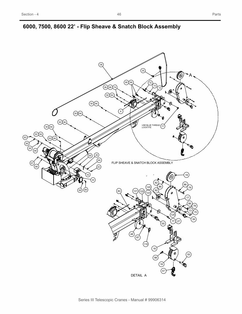
6000, 7500, 8600 22’ - Flip Sheave & Snatch Block Assembly
FLIP SHEAVE & SNATCH BLOCK ASSEMBLY
DETAIL A
6768
8450
8450
83
8450
8450
8450
748985
8
9980 7073
15
19
17
8679120
8286
82
35
38
83
85
2685
85
2685
44
42
6969
77 2755
4887
98
18
47
55
8679
39
7073120
16
110
8450
8450
USE BLUE THREAD LOCKTITE 77
12312212183
A

Section - 4 47 Parts
Series III Telescopic Cranes - Manual # 99906314
PARTS LIST
ITEM NO. PART NO. DESCRIPTION KIT NO. QTY.8. 51723610 CORD REEL ASM- 30FT W/PACKARD W/DEUTSCH 115. 52723030 PIN-TYPE M 1.50X 3.38 116. 52725155 WLDMT- A2B BRKT 117. 52725153 WLDMT-FLIP SHEAVE 118. 52725065 WLDMT- SNATCH BLOCK 119. 60030134 SHEAVE- 8.00 POLYMER 126. 70034490 PLATE-ANGLE PLASTIC 3.50” 227. 60109337 RETAINER PLT-PIN 3.00 DIA 135. 70149793 COLLAR-SHAFT 2 PIECE 11/16 IN 138. 70580182 CABLE ASM-1020in .38 6X25 FW IWRC XIPS 139. 73734752 PIN-LOCK W/HANDLE 0.75 X 4.00 W/HAIRPIN 142. 70735093 TRANSM-RAD S3 SP EM 5LED FHSS 2400 A/R44. 70735094 RECEIVER-RAD S3 SP 5LED FHSS 2400 A/R47. 70735099 HOOK-SWVL POS LOCK BBRG 5TON 148. 71414204 PLATE-SINGLE SHEAVE (20#) .38 WIRE ROPE 150. 72034485 CLAMP-PLASTIC 1/4” CABLE 855. 73734565 PIN-LOCK W/HANDLE 1.00 X 3.50 W/HAIRPIN 267. 72062194 NUT-SS .25-20 NYLOC 4 268. 72063166 WASHER-FLAT .25 R WRT 18-8 .62OD SS 4 269. 72601846 CAP SCR .25-20X 1.25 HH SS 4 270. 70034382 CAP-GREASE PRO20 GC-RED 5 673. 72053508 ZERK-NPT .12 5 474. 72060000 CAP SCR .25-20X .50 HH GR5 Z 5 277. 72060147 CAP SCR .62-11X 1.00 HH GR5 Z 5 179. 72060893 CAP SCR .38-16X 3.25 HH GR5 Z 5 280. 72062000 NUT .25-20 HEX 5 382. 72062103 NUT .38-16 HEX NYLOCK 5 283. 72062104 NUT .25-20 HEX NYLOCK 5 684. 72062106 NUT 10-24 HEX NYLOCK 5 785. 72063001 WASHER .25 FLAT 5 1886. 72063186 WASHER .38 FLAT 5 1287. 72063010 WASHER 1.00 FLAT 5 189. 72063049 WASHER .25 LOCK 5 299. 72661694 BRIDLE RING 1-1/12ID X 1/4-20 5 3110. 72661641 PIN-QUICK 5/16-2-1/16 ZINC YELLOW 5 1120. 60030486 SPACER-A2B BRACKET (7500/8600 ONLY) 2121. 60140934 GUIDE - CABLE WEAR (NARROW) 111 1122. 60140937 BRKT - CABLE GUIDE (NARROW) 111 1123. 72060006 CAP SCR .25-20X 1.50 HH GR5 Z 111 2REV. AL

Section - 4 48 Parts
Series III Telescopic Cranes - Manual # 99906314
6000, 7500, 8600 22’ - Gear Rotator, Primary (71056543)
See NOTES for corresponding numbers inside the triangles.

Section - 4 49 Parts
Series III Telescopic Cranes - Manual # 99906314
71056543 PARTS LIST
ITEM NO. PART NO. DESCRIPTION QTY.1. 70056527 SRB-E13.5-0.88-085T5 12. 70395074 ORING-PARKER #2-234 13. 70395076 SEAL-NAT’L #470565 24. 70145786 RING-SNAP SPRLX RRN-315 15. 70055271 BEARING-CONE TIM 26882 (3816) 26. 70055281 BRG-CUP TIMKEN 26830 27. 70145501 RETAINER, BEARING 3816 18. 70056550 WORM 170-10024-1 19. 70145787 HOUSING-MAIN 110. 72601734 CAP SCR-SKT 3/8NC X 1-1/4 3816 411. 72601733 CAP SCR-FERRY 1 /2NC X 1.25 3816 412. 73145506 SHIM-METAL (.005 THK) 3816 213. 73145506 SHIM-METAL (.015 THK) 3816 214. 73145504 SHIM-METAL (.030 THK) 3816 215. 76039295 GASKET-HYO MTR (.031) 116. 72533604 PLUG-EX CUP DORM #555-069 117. 72661504 PIN-DOWELL 3/8 X 1 218. 72601751 CAP SCR HX 5/8NC X 2-3/4 GR8 2319. 72063219 WASHER-PLAIN HARDND 5/8 2320. 72533605 ZERK-ALEMITE #1792B 221. 72533439 VENT PLUG-ALEMITE 328224 2REV. D
WARNINGANY TIME THE GEAR-BEARING BOLTS HAVE BEEN REMOVED, THEY MUST BE RE-PLACED WITH NEW BOLTS OF IDENTICAL GRADE AND SIZE. FAILURE TO REPLACE GEAR-BEARING BOLTS MAY RESULT IN BOLT FAILURE DUE TO METAL FATIGUE, CAUSING DEATH OR SERIOUS INJURY.
NOTES:1. Install seals #3 & #16 with Loctite plastic gasket on O.D. Lubricate seal surface before assembly.
2. Pack cavities with EPO grease.
3. Shim to obtain 0.000 / 0.004 end play on worm shaft.
4. Lubricate o-ring #2 with worm gear oil before installing.
5. Install bolts #10 with Loctite #242.
6. Set backlash between worm and rotation bearing 0.005 - 0.012.
7. Tighten 5/8 - 11 UNC grade 8 mounting bolts as follows:
• Tighten progressively and at 180º intervals.• First interval at 70 ft-lb. • Second interval at 140 ft-lb.• Third interval at 210 ft-lb.• Tighten bolts in order shown in diamonds.• Do Not use Loctite on mounting bolts.
8. Item #20 ships loose. Install item #21 for shipping.

Section - 4 50 Parts
Series III Telescopic Cranes - Manual # 99906314
6000 22’ - Lower Cylinder (51724528)
Use Seal Kit: 94399356
SECTION A-A
A
45.46 RETRACTED70.58 EXTENDED
1.63
3.25
EXTEND PORTRETRACT PORT
TEST PORT
STAMP PARALLEL TO CENTERLINE:IOWA MOLD TOOLING CO. INC.IMT P/N 51724528 REV "_"JI XXXXXX REV "_"MO/DAY/YR
25.06 STROKE
(47°) REF
14
3
4
12.02
3.25
8 5
8
17
15
8
6 8
9
2
10 11
12 11
POLYGON BUSHING
2 PCS THIS END
POLYGON BUSHING
1 PC THIS END
INSTALL AFTER PAINT SEE NOTE #3
SEE NOTE #6
SEE NOTE #4
13 13
7005537070055369
Section - 4 51 Parts
Series III Telescopic Cranes - Manual # 99906314
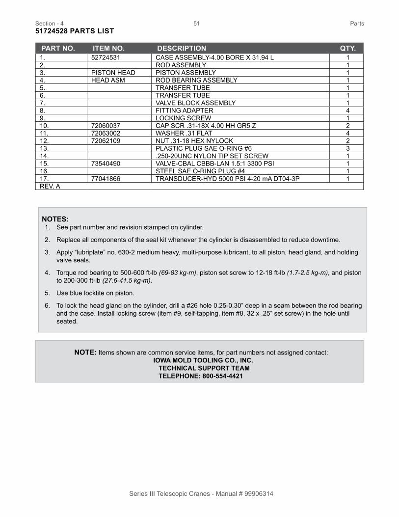
51724528 PARTS LIST
PART NO. ITEM NO. DESCRIPTION QTY.1. 52724531 CASE ASSEMBLY-4.00 BORE X 31.94 L 12. ROD ASSEMBLY 13. PISTON HEAD PISTON ASSEMBLY 14. HEAD ASM ROD BEARING ASSEMBLY 15. TRANSFER TUBE 16. TRANSFER TUBE 17. VALVE BLOCK ASSEMBLY 18. FITTING ADAPTER 49. LOCKING SCREW 110. 72060037 CAP SCR .31-18X 4.00 HH GR5 Z 211. 72063002 WASHER .31 FLAT 412. 72062109 NUT .31-18 HEX NYLOCK 213. PLASTIC PLUG SAE O-RING #6 314. .250-20UNC NYLON TIP SET SCREW 115. 73540490 VALVE-CBAL CBBB-LAN 1.5:1 3300 PSI 116. STEEL SAE O-RING PLUG #4 117. 77041866 TRANSDUCER-HYD 5000 PSI 4-20 mA DT04-3P 1REV. A
NOTES:1. See part number and revision stamped on cylinder.
2. Replace all components of the seal kit whenever the cylinder is disassembled to reduce downtime.
3. Apply “lubriplate” no. 630-2 medium heavy, multi-purpose lubricant, to all piston, head gland, and holding valve seals.
4. Torque rod bearing to 500-600 ft-lb (69-83 kg-m), piston set screw to 12-18 ft-lb (1.7-2.5 kg-m), and piston to 200-300 ft-lb (27.6-41.5 kg-m).
5. Use blue locktite on piston.
6. To lock the head gland on the cylinder, drill a #26 hole 0.25-0.30” deep in a seam between the rod bearing and the case. Install locking screw (item #9, self-tapping, item #8, 32 x .25” set screw) in the hole until seated.
NOTE: Items shown are common service items, for part numbers not assigned contact: IOWA MOLD TOOLING CO., INC. TECHNICAL SUPPORT TEAM TELEPHONE: 800-554-4421

Section - 4 52 Parts
Series III Telescopic Cranes - Manual # 99906314
7500 22’ - Lower Cylinder (51723577)
1
2
65
78
8
8
8
34
9
TE
ER
STAMP PART NO. AND REVISION HERE
17 1112
1112
11 10 11 1015
13
13
14
POLYGON BUSHING70055370(2 PCS THIS END)
POLYGON BUSHING70055369(1 PC THIS END)
EXTENDPORT
RETRACTPORT
TESTPORT 16
45°
25.06" STROKE
45.52" RETRACTED70.58" EXTENDED
STAMP THIS AREA
,
PISTON SEALS
ITEM NO. DESCRIPTION QTY.1 PISTON 12 PISTON SEAL 13 O-RING 14 WEAR RING (PISTON) 2
ITEM NO. QTY.1 ROD BEARING 12 ROD SEAL 13 WIPER 14 BACKUP RING 15 WEAR RING 26 O-RING 1
ROD BEARING SEALS
DESCRIPTION
SECTION A-A
1
24 4
3
A
A
1
3
25
5
6 4
A
A
SECTION A-A

Section - 4 53 Parts
Series III Telescopic Cranes - Manual # 99906314
NOTES:1. See part number and revision stamped on cylinder.
2. Replace all components of the seal kit whenever the cylinder is disassembled to reduce downtime.
3. Apply “lubriplate” no. 630-2 medium heavy, multi-purpose lubricant, to all piston, head gland, and holding valve seals.
4. Torque rod bearing to 500-600 ft-lb (69-83 kg-m), piston set screw to 12-18 ft-lb (1.7-2.5 kg-m), and piston to 200-300 ft-lb (27.6-41.5 kg-m).
5. Use blue locktite on piston.
6. To lock the head gland on the cylinder, drill a #26 hole 0.25-0.30” deep in a seam between the rod bearing and the case. Install locking screw (item #9, self-tapping, item #8, 32 x .25” set screw) in the hole until seated.
51723577 PARTS LIST
ITEM NO. PART NO. DESCRIPTION QTY.1. 52723913 CASE-4.25 BORE X 33.50 LG 12. 52723915 ROD ASM-2.25 DIA X XX.XX LG 13. 71414679 PISTON-4.25 BORE SIII 14. 71414680 ROD BEARING-4.25 BORE X 2.25 ROD 15. 71414693 TUBE, TRANSFER 16. 71414694 TUBE, TRANSFER 17. 73540444 VALVE BLOCK ASSEMBLY W/PRESS TRANSDUCER 18. FITTING ADAPTER 49. LOCKING SCREW 110. 5/16”-18 X 4.00 HEX BOLT GR5 211. .31 FLAT WASHER 412. .31-18 NYLOC NUT 213. PLASTIC PLUG SAE O-RING #6 314. .250-20 UNC NYLON TIP SET SCREW 115. 73540490 VALVE-CBAL CBBB-LAN 1.5:1 3300 PSI 116. STEEL SAE O-RING PLUG #4 117. 77041866 TRANSDUCER-HYD 0-5000PSI 4-20mA 2-Wire 1REF 94399127 SEAL KIT 1REV. B
NOTE: Items shown are common service items, for part numbers not assigned contact: IOWA MOLD TOOLING CO., INC. TECHNICAL SUPPORT TEAM TELEPHONE: 800-554-4421

Section - 4 54 Parts
Series III Telescopic Cranes - Manual # 99906314
8600 22’ - Lower Cylinder (51723170)
1265
78
871
16
3 4
9
TE
ER
STAMP PART NO.AND REVISION DATE.
POLYGON BUSHING700553691 PC. THIS END
45°
25.06" STROKE
45.52" RETRACTED70.58" EXTENDED
TESTPORT
RETRACTPORT EXTEND
PORT
13
13
14
STAMPTHIS
AREA
POLYGON BUSHING700553702 PCS. THIS END
11 10 11 10 15
11 121112
A-A NOITCES
1
24 4
3
A
A
PISTON SEALS
ITEM NO. DESCRIPTION QTY.1 PISTON 12 PISTON SEAL 13 O-RING 14 WEAR RING (PISTON) 2
SECTION A-A1
3
26
6
4 5
A
A
ITEM NO. QTY.1 ROD BEARING 12 ROD SEAL 13 WIPER 14 O-RING 15 BACKUP RING 16 WEAR RING 2
ROD SEALS
DESCRIPTION

Section - 4 55 Parts
Series III Telescopic Cranes - Manual # 99906314
51723170 PARTS LIST
ITEM NO. PART NO. DESCRIPTION QTY.1. 52723914 CASE-4.25 BORE X 33.50 LG 12. 52723915 ROD ASM-2.25 DIA X XX.XX LG 13. 71414681 PISTON-4.25 BORE SIII 14. 71414682 ROD BEARING-4.25 BORE X 2.25 ROD 15. 71414693 TUBE, TRANSFER 16. 71414694 TUBE, TRANSFER 17. 73540444 VALVE BLOCK ASSEMBLY W/PRESS TRANSDUCER 18. FITTING ADAPTER 49. LOCKING SCREW 110. 5/16”-18 X 4.00 HEX BOLT GR5 211. .31 FLAT WASHER 412. .31-18 NYLOC NUT 213. PLASTIC PLUG SAE O-RING #6 314. .250-20 UNC NYLON TIP SET SCREW 115. 73540490 VALVE-CBAL CBBB-LAN 1.5:1 3300 PSI 116. STEEL SAE O-RING PLUG #4 117. 77041866 TRANSDUCER-HYD 0-5000PSI 4-20mA 2-Wire 1REF 94399128 SEAL KIT 1REV. D
NOTES:1. See part number and revision stamped on cylinder.
2. Replace all components of the seal kit whenever the cylinder is disassembled to reduce downtime.
3. Apply “lubriplate” no. 630-2 medium heavy, multi-purpose lubricant, to all piston, head gland, and holding valve seals.
4. Torque rod bearing to 500-600 ft-lb (69-83 kg-m), piston set screw to 12-18 ft-lb (1.7-2.5 kg-m), and piston to 200-300 ft-lb (27.6-41.5 kg-m).
5. Use blue locktite on piston.
6. To lock the head gland on the cylinder, drill a #26 hole 0.25-0.30” deep in a seam between the rod bearing and the case. Install locking screw (item #9, self-tapping, item #8, 32 x .25” set screw) in the hole until seated.
NOTE: Items shown are common service items, for part numbers not assigned contact: IOWA MOLD TOOLING CO., INC. TECHNICAL SUPPORT TEAM TELEPHONE: 800-554-4421

Section - 4 56 Parts
Series III Telescopic Cranes - Manual # 99906314
6000, 7500, 8600 22’ - Extension Cylinder (51723174)
66
9 109
17 17
3
6 1614 15 12 5 11 4 13
1 2
1614
17
8
18
19
SECTION B-B
STAMP PART # AND REVISION DATE
3 CLAMPS EVENLY SPACED.CLAMPS ORIENTED AS SHOWN.
25º
B
B A
139.11” RETRACTED - 256.11” EXTENDED - 117” STROKE
SECTION A-A
59.73” STROKE 57.27” STROKE 7

Section - 4 57 Parts
Series III Telescopic Cranes - Manual # 99906314
NOTES:1. See part number and revision stamped on cylinder.
2. Replace all components of the seal kit whenever the cylinder is disassembled to reduce downtime.
3. Apply Lubriplate No. 630-2 medium heavy, multi-purpose lubricant to all piston, head gland, and holding valve seals.
4. Torque piston nut (3/4-16 UNF) to 170.9 ft-lb (23.6 kg-m), torque piston to 200 ft-lb (27.6 kg-m).
5. Use blue Locktite on piston.
6. To lock the head gland on the cylinder, drill a #26 hole 0.25-0.30” deep in a seam between the rod bearing and the case. Install locking screw (item #16, self-tapping, item #8-32 x .25” set screw) in the hole until seated.
7. Use anti-seez on 1/4-20 bolts. (Item #19)
51723174 PARTS LIST
ITEM NO. PART NO. DESCRIPTION QTY.1. 52723910 CASE-2.00 BORE X132.84 LG 12. 52723911 ROD ASM-1.25 DIA X XX.XX LG 13. 52723912 ROD ASM-1.50 DIA X XX.XX LG 14. 71414674 PISTON-2.00 BORE SIII 15. 71414675 PISTON-2.00 BORE SIII 16. 71414676 ROD BEARING-2.0 BORE X 1.50 ROD 17. 71414677 ROD BEARING-2.0 BORE X 1.25 ROD 18. 73540565 VALVE-CBAL 15 GPM 4.5:1 T11-A @4000 PSI 19. PLASTIC PLUG SAE O-RING #8 210. STEEL SAE O-RING PLUG #4 111. SELF-LOCKING NUT .75-16 UNF 112. .250-20 UNC NULON TIP SET SCREW 113. 73050198 STROKE STOP-51723174 114. 215. 71414678 TUBE, TRANSFER 116. 217. 318. 71416609 ROD END CAP 119. 71416610 CAP SCREW .25-20 X 1.50 SHCS GR8 4REF 94399126 SEAL KIT 1REV. D
NOTE: Items shown are common service items, for part numbers not assigned contact: IOWA MOLD TOOLING CO., INC. TECHNICAL SUPPORT TEAM TELEPHONE: 800-554-4421

Section - 4 58 Parts
Series III Telescopic Cranes - Manual # 99906314
6000, 7500, 8600 22’ - Planetary Winch - 5500 lb Line (70570761)
NOTE: Items shown are common service items, for part numbers not assigned contact: IOWA MOLD TOOLING CO., INC. TECHNICAL SUPPORT TEAM TELEPHONE: 800-554-4421
���
39
38
17
33
33
71
52
89
3
5316
1513
1416
1211
10
51
50
3029
4748
42 3635
34
3231
2728
2
41
46
45
56
4
44
4049 43
45
37
���
Section - 4 59 Parts
Series III Telescopic Cranes - Manual # 99906314
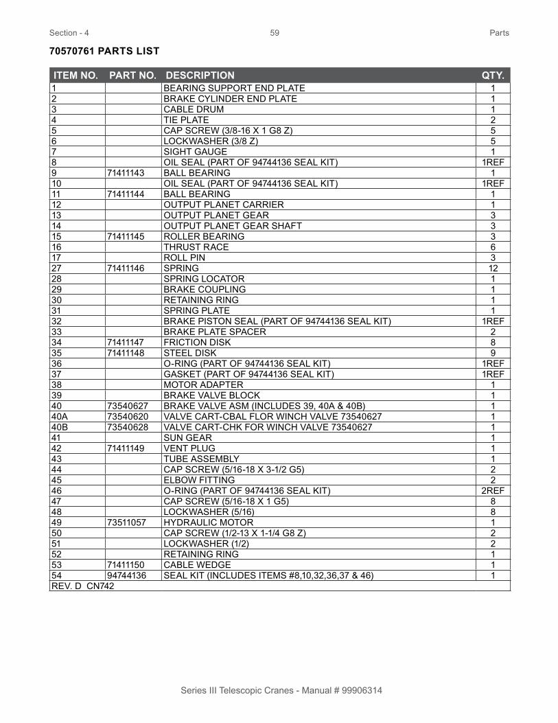
70570761 PARTS LIST
ITEM NO. PART NO. DESCRIPTION QTY.1 BEARING SUPPORT END PLATE 12 BRAKE CYLINDER END PLATE 13 CABLE DRUM 14 TIE PLATE 25 CAP SCREW (3/8-16 X 1 G8 Z) 56 LOCKWASHER (3/8 Z) 57 SIGHT GAUGE 18 OIL SEAL (PART OF 94744136 SEAL KIT) 1REF9 71411143 BALL BEARING 110 OIL SEAL (PART OF 94744136 SEAL KIT) 1REF11 71411144 BALL BEARING 112 OUTPUT PLANET CARRIER 113 OUTPUT PLANET GEAR 314 OUTPUT PLANET GEAR SHAFT 315 71411145 ROLLER BEARING 316 THRUST RACE 617 ROLL PIN 327 71411146 SPRING 1228 SPRING LOCATOR 129 BRAKE COUPLING 130 RETAINING RING 131 SPRING PLATE 132 BRAKE PISTON SEAL (PART OF 94744136 SEAL KIT) 1REF33 BRAKE PLATE SPACER 234 71411147 FRICTION DISK 835 71411148 STEEL DISK 936 O-RING (PART OF 94744136 SEAL KIT) 1REF37 GASKET (PART OF 94744136 SEAL KIT) 1REF38 MOTOR ADAPTER 139 BRAKE VALVE BLOCK 140 73540627 BRAKE VALVE ASM (INCLUDES 39, 40A & 40B) 140A 73540620 VALVE CART-CBAL FLOR WINCH VALVE 73540627 140B 73540628 VALVE CART-CHK FOR WINCH VALVE 73540627 141 SUN GEAR 142 71411149 VENT PLUG 143 TUBE ASSEMBLY 144 CAP SCREW (5/16-18 X 3-1/2 G5) 245 ELBOW FITTING 246 O-RING (PART OF 94744136 SEAL KIT) 2REF47 CAP SCREW (5/16-18 X 1 G5) 848 LOCKWASHER (5/16) 849 73511057 HYDRAULIC MOTOR 150 CAP SCREW (1/2-13 X 1-1/4 G8 Z) 251 LOCKWASHER (1/2) 252 RETAINING RING 153 71411150 CABLE WEDGE 154 94744136 SEAL KIT (INCLUDES ITEMS #8,10,32,36,37 & 46) 1REV. D CN742
Section - 4 60 Parts
Series III Telescopic Cranes - Manual # 99906314
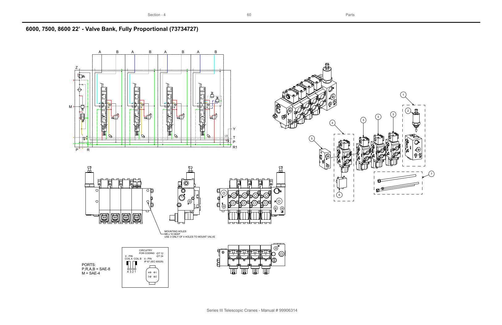
6000, 7500, 8600 22’ - Valve Bank, Fully Proportional (73734727)
A
Z
M
P R
Y
TP
LS
Z
R1
B A B A B A B
PORTS:P,R,A,B = SAE-8M = SAE-4
5
33
32
1
6
7
4
MOUNTING HOLESM8 x 10 DEEPUSE 3 ONLY OF 4 HOLES TO MOUNT VALVE
4 3 12 4
3
1
2
CIRCUITRYFOR CODING -DT 12
-DT 244 - PINIP 67 (IEC 60529)
4 - PINCOIL A COIL B

Section - 4 61 Parts
Series III Telescopic Cranes - Manual # 99906314
73734727 PARTS LIST
ITEM NO. PART NO. DESCRIPTION QTY.1. 73540534 SECT-PSL2 S3FP INLET OPEN CENTER COMP 12. 73540538 RELIEF VALVE-PSL2 FOR 73734727 @ 3200PSI 13. 73540535 SECT-PSL2 S3FP WINCH/EXT/MAIN 12VDC 34. 73540536 SECT-PSL2 S3FP ROTATION 12VDC 15. 73540537 SECT-PSL2 S3FP END PLATE 16. 77040598 COIL-PSL 12VDC DEUTSCH 47. 73540616 TIE ROD KIT-PSL2 4-SECTION 18. 94399213 SEAL KIT-73734727 CONNECTION BLOCK (NOT SHOWN) 19. 94399214 SEAL KIT - 73734727 SECTIONS (NOT SHOWN) 1REV. D

Section - 4 62 Parts
Series III Telescopic Cranes - Manual # 99906314
6000, 7500, 8600 22’ - Valve Bank, Single Proportional (73734472)
X B1 A1 B2 A2 B3 A3 B4 A4 BR
PSI3200
P
T
WINCHEXTENSIONMAINROTATION
RELEASE VALVEWINCH BRAKE
2
7
4
6
5
88
8
13
12
9
1112
3
10
8
1
14
17
15
16

Section - 4 63 Parts
Series III Telescopic Cranes - Manual # 99906314
73734472 PARTS LIST
ITEM NO. PART NO. DESCRIPTION QTY.1. 73540617 SECT-BV18 INLET ASM S3SP W RELIEF @ 3200 12. 73540394 SECT-BV18 INLET BODY S3SP 13. 73540252 VALVE-CART-P FLOW CTRL 12 VDC W MNL OVRD 14. 73540253 COIL-FOR 73540252 12VDC DEUTSCH 15. 73540397 VALVE-BRAKE RELEASE NO 12VDC DEUTSCH 16. 73540256 COIL-S SERIES FOR 73540397 12VDC DEUTSCH 17. 73540396 RELIEF VALVE-FOR 73734472 @ 3200 PSI 18. 73540375 SECT-BV18 S3SP 12VDC DEUTSCH 49. 77041930 SOLENOID TUBE USED ON 73540375 810. 90744198 KIT-COIL REPAIR FOR 73540375 12V 811. 73540027 END PLATE-BV18 W TURNAROUND 112. 70145830 BRKT-MOUNTING EXTRA LONG 213. 73540618 TIE ROD KIT-BV18 4-SECTION 114. 72533507 ELBOW-M STR/90/M JIC 8 10 115. 72532358 ADPTR-M STR/M JIC 8 8 416. 72532356 ADPTR-M STR/M JIC 8 6 517. 72053758 ELBOW-M STR/90/M JIC 4 4 1REV. E

Section - 4 64 Parts
Series III Telescopic Cranes - Manual # 99906314
6000, 7500, 8600 22’ - Connection Block Seal Kit For 73734727 (94399213)
104
101100
101100
109110
108A
108112
113
111
102
115
116
118117

Section - 4 65 Parts
Series III Telescopic Cranes - Manual # 99906314
94399213 PARTS LIST
ITEM NO. DESCRIPTION QTY.100. O-RING-2.90X1.78 Z24 4101. O-RING-10.82X1.78 P5001 3102. O-RING-12.42X1.78 P5001 1104. O-RING-17.17 X 1.78 P 5001 1108. COPPER RING-SHAPE A DIN 7603 10X14X1.5-CU 1108A. FITTING SEAL 1109. SEAL RING-8.3X11X1.15 PTFE 7625 109/1 1110. SEAL-1/4” DRV 1111. O-RING-9X1.5 NBR 90 SH 1112. O-RING-12.42X1.78 P5001 1113. O-RING-14.03X2.61 P5001 94 SH A 1115. SEAL-G 1/4” DRV 100116-NB 650 NBR 2116. O-RING-15X2 HNBR 90 SH RED SPOT 1117. O-RING-23.52X1.78 HNBR 90 SH RED SPOT 1118. SEAL RING-27X32X2 ST 1REV. INITIAL RELEASE
NOTE: these seals are part of kit no. 94399213, And cannot be purchased individually.

Section - 4 66 Parts
Series III Telescopic Cranes - Manual # 99906314
6000, 7500, 8600 22’ - Seal Kit for 73734727 (94399214)
114117
114117
113113
116
116
116
116
115
115
120
111111110
106106
106106
105105
100102
100
100101
104
100102
103
100100
102
109108
109108200
119
118 108106
105108106
6 Nm
6 Nm6 Nm
6 Nm
104112112
121
121

Section - 4 67 Parts
Series III Telescopic Cranes - Manual # 99906314
94399214 PARTS LIST
ITEM NO. DESCRIPTION QTY.100. O-RING- 1 .78 x 1.02 mm 2101. O-RING - 6.75 x 1.75 mm P5001 2102. O-RING - 25.07 x 2.62 mm Z24 1103. USIT-RING - ST 37 STANDARD 1104. O-RING - 26.7 x 1.78 mm Z24 1105. O-RING - 12.42 x 1.78 mm P5001 3106. O-RING - 2.90 x 1.78 mm Z24 6108. O-RING - 10.82 x 1.78mm P5001 6109. O-RING - 6.07 x 1.78 mm P5001 4110. O-RING - 3 x 1.5 mm 2111. O-RING - 6.75 x 1.78 mm P5001 2112. SEAL NUT 2113. USIT-RING - ST 37 STANDARD 2114. COPPER RING - 4 x 8 x 1 mm 2115. SOFT IRON SEAL RING - 2116. O-RING - 17.17 x 1.78 mm P5001 2117. SEAL- LOCK COLLAR NUT - M6 12 x 1 2118. O-RING - 10.00 x 1.00 mm P5001 1119. O-RING - 5.00 x 1.00 mm P5001 2120. COPPER RING - 5 x 7.5 x 1 mm 1121. SEAL NUT 2REV. INITIAL RELEASE
NOTE: These seals are part of kit no. 94399214, and cannot be purchased individually.
Section - 4 68 Parts
Series III Telescopic Cranes - Manual # 99906314
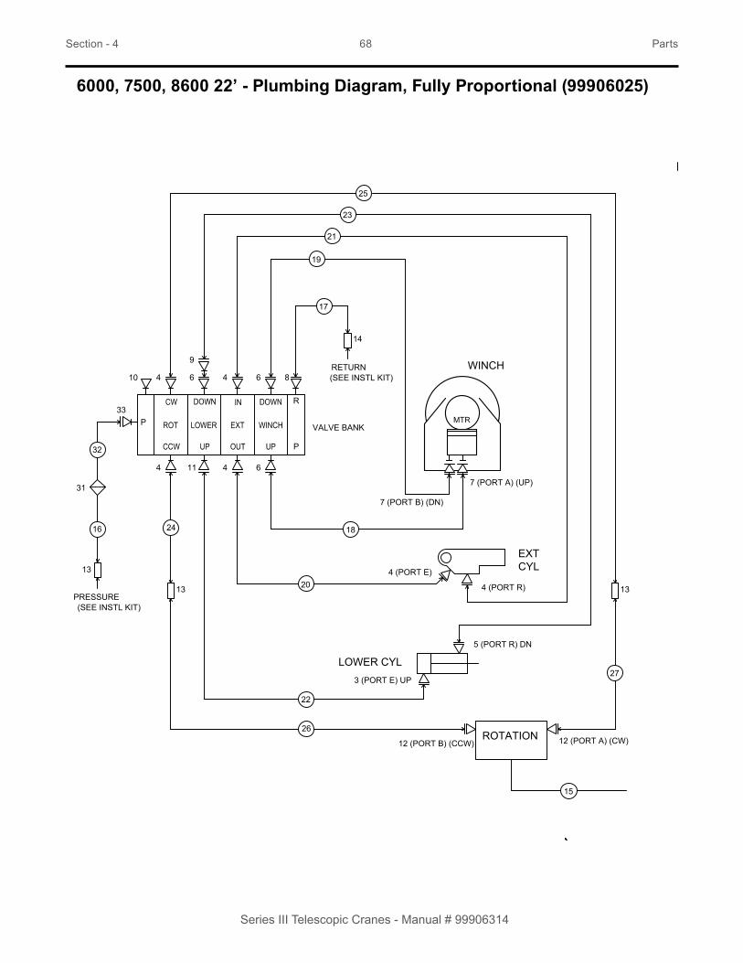
6000, 7500, 8600 22’ - Plumbing Diagram, Fully Proportional (99906025)
12 (PORT B) (CCW)
4 (PORT R)
4 (PORT E)
ROTATION
4
R
18
17
14
22
20
19
21
3 (PORT E) UP
5 (PORT R) DN
LOWER CYL
23
4 611
6464
VALVE BANK
8
12 (PORT A) (CW)26
13
25
13
24
27
10
MTR
WINCH
7 (PORT A) (UP)
(SEE INSTL KIT)RETURN
P
9
15
7 (PORT B) (DN)
CYLEXT
(SEE INSTL KIT)PRESSURE
P
31
13
33
16
32

Section - 4 69 Parts
Series III Telescopic Cranes - Manual # 99906314
99906025-1 PLUMBING DIAGRAM, FULLY PROPORTIONAL (CONTINUED)
PORT IDENTIFICATIONSPLANETARY WINCH
#7#7
PORT A
PORT B
WINCH (BOTTOM VEIW)
#15 GREASE HOSE
(ROTATION )PORT IDENTIFICATIONSHYDRAULIC MOTOR
PORT APORT B
#12
#12
PRESSURE & RETURN HOSES
MAIN CYL
#5
#3
TRANSDUCER
COUNTERBALANCEVALVE
MAIN CYLINDERPORT IDENTIFICATIONS
EXTENSION CYLINDERPORT IDENTIFICATION
60350105 SLEEVE
ROTATION CW
MAIN CYL (RETRACT)
EXT CYL (RETRACT)
WINCH (DOWN)
ROTATION CCW
MAIN CYL (EXTEND)
EXT CYL (EXTEND)
WINCH (UP)
RETURN (TANK)
PRESSURE

Section - 4 70 Parts
Series III Telescopic Cranes - Manual # 99906314
99906025 PARTS LIST
ITEM NO. PART NO. DESCRIPTION KIT NO. QTY.1. 91726822 KIT-HYD BG4 SERIES III FP 7500/8600S 12. 73734727 VALVE BANK-4SEC 4R 10GPM TELE PROP 12V G 1REF3. 72532355 ADPTR-M STR/M JIC 6 6 1 14. 72532356 ADPTR-M STR/M JIC 8 6 1 65. 72532357 ADPTR-M STR/M JIC 6 8 1 16. 72532358 ADPTR-M STR/M JIC 8 8 1 47. 72532359 ADPTR-M STR/M JIC 10 8 1 28. 72532361 ADPTR-M STR/M JIC 8 10 1 19. 72532670 ELBOW-M JIC/45/F JIC 8 8 1 110. 72532686 PLUG-STR SOC HD STL 8 ( .75 THD) 1 111. 72533583 ELBOW-M STR/45/M JIC 8 6 1 112. 72533613 ADPTR-M STR/M JIC 10 6 1 213. 72533648 SWIVEL-M JIC/90/M JIC 8 8 1 314. 72534412 SWIVEL-M JIC/90/M JIC 10 10 1 115. 51395121 HOSE-AA .13 X 13.50 (2-2) 100R17 1 116. 51399890 HOSE-FJJ .50 X 40.00 (8-8) 100R17 1 117. 51397080 HOSE-FJ .62 X 30.00 (10-10) 100R17 1 118. 51397081 HOSE-FZ .50 X 31.50 (8-8) 100R17 1 119. 71397082 HOSE-FJ .50 X 31.00 (8-8) 100R17 1 120. 51396810 HOSE-JZ .38 X 21.50 (6-6) 100R17 180 1 121. 51396811 HOSE-JJ .38 X 23.00 (6-6) 100R17 180 1 122. 51399077 HOSE-FJ .38 X 30.00 (6-6) 100R17 1 123. 51399078 HOSE-FZ .50 X 32.00 (8-8) 100R17 1 124. 51399072 HOSE-FJ .38 X 22.50 (8-6) 100R17 1 125. 51399073 HOSE-FZ .38 X 25.00 (8-6) 100R17 1 126. 51399228 HOSE-FJ .38 X 18.00 (8-6) 100R17 1 127. 51399229 HOSE-FJ .38 X 22.00 (8-6) 100R17 1 128. 60350141 SLEEVE-HOSE NHS-159 X 12 CUT & SEALED 1 129. 60350142 SLEEVE-HOSE NHS-254 X 15 CUT & SEALED 1 330. 60350105 HOSE SLEEVE-WRAP AROUND 4in DIA 231. 73052156 FILTER-PRES 4000PSI 25GPM 10MIC -12 132. 71415690 TUBE ASM-PRESSURE FILTER S3FP SMALL MAST 133. 72534898 O-RING EXTENDER 08-08 1REV. A
NOTES:1. See sheet 2 for winch hydraulic motor, lower and extension cylinder.
2. Install 60350141 on extension cylinder, main cylinder hoses and rotation hoses.
3. Install 60350142 on winch hoses, pressure and return valve bank hoses.
4. Install 60350105 on pressure & return hoses, and rotation hoses through mast.

This page left intentionally blank
71
Series III Telescopic Cranes - Manual # 99906314

Section - 4 72 Parts
Series III Telescopic Cranes - Manual # 99906314
6000, 7500, 8600 22’ - Plumbing Diagram, Single Proportional (99906026)
8 (PORT B) (CCW)ROTATION
P
14
1310
18
16
15
17
2 (PORT E) UP
4 (PORT R) DN
LOWER CYL
19
7
6
VALVE BANK
8 (PORT A) (CW)22
9
21
9
20
23
MTR
WINCH
5 (PORT A) (UP)
RETURN
129
11
5 (PORT B)
R
(SEE INSTL KIT)
PRESSURE
(DN)
3 (PORT R)
3 (PORT E) CYLEXT
T2
BR
WINCHBRAKETUBE
ASSEMBLY(EXISTING)
28
27
(SEE NOTE #5)

Section - 4 73 Parts
Series III Telescopic Cranes - Manual # 99906314
99906026-1 PLUMBING DIAGRAM, SINGLE PROPORTIONAL (CONTINUED)
VALVE BANK PORTIDENTIFICATION
PORT APORT B
HYDRAULIC MOTORPORT INDICATIONS(ROTATION)
ROTATION CW
WINCH (DOWN)
MAIN CYL (EXTEND)
MAIN CYL (RETRACT)PRESSURE
BRAKE
PORT A
PORT B
WINCH (BOTTOM VIEW)
WINCH

Section - 4 74 Parts
Series III Telescopic Cranes - Manual # 99906314
99906026 PARTS LIST
ITEM NO. PART NO. DESCRIPTION KIT NO. QTY.1. 91726823 KIT-HYD BG4 SERIES III FP 7500/8600S 12. 72532355 ADPTR-M STR/M JIC 6 6 1 13. 72532356 ADPTR-M STR/M JIC 8 6 1 64. 72532357 ADPTR-M STR/M JIC 6 8 1 15. 72532359 ADPTR-M STR/M JIC 10 8 1 26. 72532670 ELBOW-M JIC/45/F JIC 8 8 1 17. 72533583 ELBOW-M STR/45/M JIC 8 6 1 18. 72533613 ADPTR-M STR/M JIC 10 6 1 29. 72533648 SWIVEL-M JIC/90/M JIC 8 8 1 310. 72534412 SWIVEL-M JIC/90/M JIC 10 10 1 111. 51395121 HOSE-AA .13 X 13.50 (2-2) 100R17 1 112. 51396017 HOSE-FJ .50 X 30.00 (8-8) 100R16 1 113. 51397080 HOSE-FJ .62 X 30.00 (10-10) 100R17 1 114. 51397081 HOSE-FZ .50 X 31.50 (8-8) 100R17 1 115. 51397082 HOSE-FJ .50 X 31.00 (8-8) 100R17 1 116. 51396810 HOSE-JZ .38 X 21.50 (6-6) 100R17 180 1 117. 51396811 HOSE-JJ .38 X 23.00 (6-6) 100R17 180 1 118. 51399462 HOSE-FJ .38 X 31.00 (6-6) 100R17 1 119. 51399463 HOSE-FZ .50 X 32.00 (8-8) 100R17 1 120. 51399072 HOSE-FJ .38 X 22.50 (8-6) 100R17 1 121. 51399073 HOSE-FZ .38 X 25.00 (8-6) 100R17 1 122. 51399228 HOSE-FJ .38 X 18.00 (8-6) 100R17 1 123. 51399229 HOSE-FJ .38 X 22.00 (8-6) 100R17 1 124. 60350141 SLEEVE-HOSE NHS-159 X 12 CUT & SEALED 1 325. 60350142 SLEEVE-HOSE NHS-254 X 15 CUT & SEALED 1 226. 51726820 KIT-BRADEN WINCH BRAKE RELEASE 127. 72534582 TEE-STL STR/JIC/JIC 4 4 4 RUN 26 128. 51399908 HOSE-FF .25 X 32.00 (4-4) 100R17 26 1REV. A
NOTES:1. See sheet 2 for winch hydraulic motor, lower and extension cylinder.
2. Install 60350141 on extension cylinder, main cylinder hoses and rotation hoses.
3. Install 60350142 on winch hoses, pressure and return valve bank hoses.
4. Install 60350105 on pressure & return hoses, and rotation hoses through mast.
5. Remove brake hose from fitting in winch motor block. Remove and replace fitting with tee (item #27). Reinstall hose onto tee.

Section - 5 75 Electrical & Lighting
Series III Telescopic Cranes - Manual # 99906314
Section - 5Electrical & Lighting

Section - 5 76 Electrical & Lighting
Series III Telescopic Cranes - Manual # 99906314
6000, 7500, 8600 22’ - LED Boom Tip Light Kit (99905289)
3
2
3
3
3
4
5
62

Section - 5 77 Electrical & Lighting
Series III Telescopic Cranes - Manual # 99906314
99905289 PARTS LIST
ITEM NO. PART NO. DESCRIPTION KIT NO. QTY.1. 51724116 ELECT KIT-S3 BOOM DUAL LED FLOOD LIGHTS 12. 77040581 FLOODLIGHT-LED 12-36VDC 1 23. 72063002 WASHER-FLAT .31 W ANSI B27.2 Z 1 44. 77045888 TERM-PKRD WEATHERPACK 14-16GA FEMALE 1 45. 77044927 CABLE SEAL-PKRD WP/MP 14 GA GREY 1 46. 77044574 CONN-PKRD WEATHERPACK 2 CAV FEMALE/TOWER 1 2REV. C

Section - 5 78 Electrical & Lighting
Series III Telescopic Cranes - Manual # 99906314
6000, 7500, 8600 22’ - Radio Remote Harness (77441481)
AB
J4
J3
J2
J1 ROTATE CW / CCW
BOOM UP / DOWN
BOOM EXT / RE T
WINCH UP / DOWN
WINCH OUTLIMIT SWITCH
WINCH OUT LIMIT SWITCH JUMPER
ANTI-TWO / BOOM FLOOD LIGHT
PRESSURE TRANSDUCER
SPARE POWER
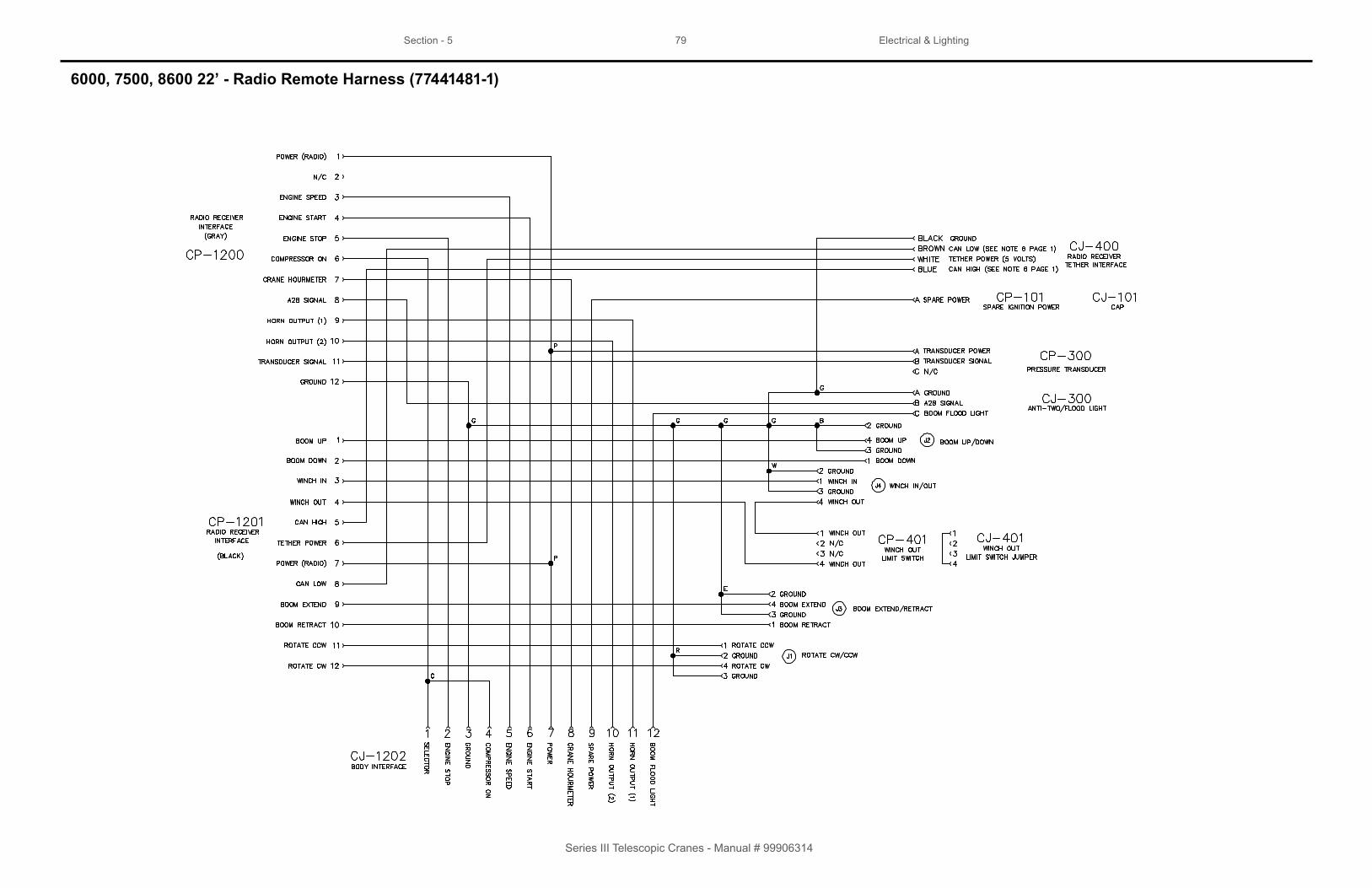
Section - 5 79 Electrical & Lighting
Series III Telescopic Cranes - Manual # 99906314
6000, 7500, 8600 22’ - Radio Remote Harness (77441481-1)

Section - 5 80 Electrical & Lighting
Series III Telescopic Cranes - Manual # 99906314
6000, 7500, 8600 22’ - Radio Remote Harness (77441537)
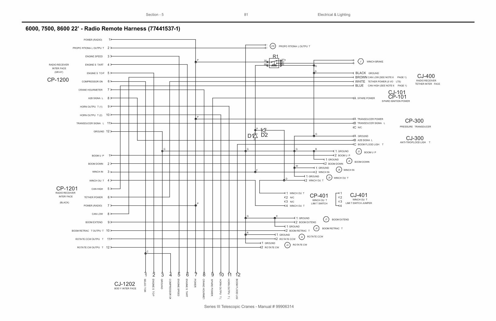
Section - 5 81 Electrical & Lighting
Series III Telescopic Cranes - Manual # 99906314
6000, 7500, 8600 22’ - Radio Remote Harness (77441537-1)
12ROTATE CW OUTPU T
BOOM EXTEND
CAN LOW
BOOM DOWN
CP-1201RADIO RECEIVER
INTER FACE TETHER POWER
CAN HIGH
POWER (RADIO)
WINCH OU T
WINCH IN
BOOM U P
9
8
1
CJ-1202
2 3 54 6 7 8
2
6
7
5
4
3
1
10
11
12
INTER FACE
GROUND
TRANSDUCER SIGNA L
HORN OUTPU T (1)
HORN OUTPU T (2)
ENGINE S TART
CP-1200
CRANE HOURMETER
COMPRESSOR ON
9
7
6
3
4
1
RADIO RECEIVER
BOOM DOWN
PROPO RTIONA L OUTPU T 2
ENGINE S TOP 5
A2B SIGNA L 8
ROTATE CCW OUTPU T 11
BOOM RETRAC T OUTPU T 10
(GR AY)
(BLACK)
POWER (RADIO)
ENGINE SPEED
ANTI-TWO/FLOOD LIGH T
G
BGG
PRESSURE TRANSDUCER
BOOM RETRAC T
P
C
ROTATE CCW
WINCH IN
G
SE
LEC
TOR
EN
GIN
E S
TOP
GR
OU
ND
CO
MP
RE
SS
OR
ON
EN
GIN
E S
PE
ED
EN
GIN
E S
TAR
T
PO
WE
R
CR
AN
E H
OU
RM
ETE
R
9 10
SP
AR
E P
OW
ER
HO
RN
OU
TPU
T (2)
ROTATE CW
ROTATE CCW
12
GROUND
BOOM RETRAC T
BOOM EXTEND2GROUND
WINCH OU T
WINCH IN
GROUND
BOOM DOWN
BOOM U P
GROUND
N/C
TRANSDUCER SIGNA LBC
A2B SIGNA L
AB
GROUND
CAN LOW (SEE NOTE 6 PAGE 1)
BLACKBROWN
BLUE
GROUND
TETHER POWER (5 VO LTS)WHITECAN HIGH (SEE NOTE 6 PAGE 1)
11 12
HO
RN
OU
TPU
T (1)
BO
OM
FLOO
D LIG
HT
RADIO RECEIVERTETHER INTER FACE
CJ-400
CP-300
CJ-300
BOD Y INTER FACE
A TRANSDUCER POWER
P
BOOM FLOOD LIGH TC
E
GROUND
1 GROUND
WGROUND
GROUND
R
2
1
12
ROTATE CW
BOOM EXTEND
21
WINCH OU T
21
21
BOOM U P21
21
PROPO RTIONA L OUTPU T
2
1WINCH BRAKE
G
D
F
A
D2D11 2
1
2
8630
8785
87aR1
P
G
SPARE POWERASPARE IGNITION POWER
CJ-101
N/C
12
WINCH OU T
WINCH OU TCP-401 1
2WINCH OU T
CJ-401LIMI T SWITCH LIMI T SWITCH JUMPERN/C3
WINCH OU T434
G
CP-101

This page left intentionally blank
82
Series III Telescopic Cranes - Manual # 99906314

83
Section - 6General Information

Section - 6 84 General Information
Series III Telescopic Cranes - Manual # 99906314
6000, 7500, 8600 22’ - Decal Placement
34
4
3
3 9
9
8
6
5
1
2
3
4
2423
22
2521
2423
2210
21 25
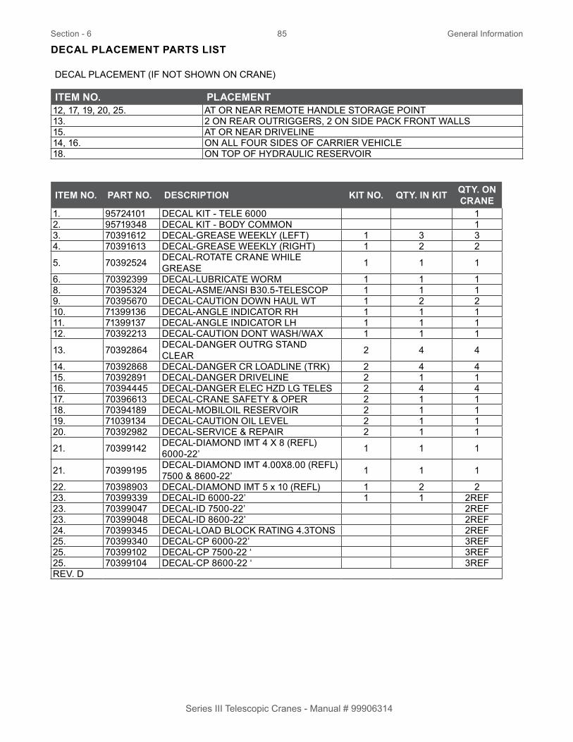
Section - 6 85 General Information
Series III Telescopic Cranes - Manual # 99906314
DECAL PLACEMENT PARTS LIST
DECAL PLACEMENT (IF NOT SHOWN ON CRANE)
ITEM NO. PLACEMENT12, 17, 19, 20, 25. AT OR NEAR REMOTE HANDLE STORAGE POINT13. 2 ON REAR OUTRIGGERS, 2 ON SIDE PACK FRONT WALLS15. AT OR NEAR DRIVELINE14, 16. ON ALL FOUR SIDES OF CARRIER VEHICLE18. ON TOP OF HYDRAULIC RESERVOIR
ITEM NO. PART NO. DESCRIPTION KIT NO. QTY. IN KIT QTY. ON CRANE
1. 95724101 DECAL KIT - TELE 6000 12. 95719348 DECAL KIT - BODY COMMON 13. 70391612 DECAL-GREASE WEEKLY (LEFT) 1 3 34. 70391613 DECAL-GREASE WEEKLY (RIGHT) 1 2 2
5. 70392524 DECAL-ROTATE CRANE WHILE GREASE 1 1 1
6. 70392399 DECAL-LUBRICATE WORM 1 1 18. 70395324 DECAL-ASME/ANSI B30.5-TELESCOP 1 1 19. 70395670 DECAL-CAUTION DOWN HAUL WT 1 2 210. 71399136 DECAL-ANGLE INDICATOR RH 1 1 111. 71399137 DECAL-ANGLE INDICATOR LH 1 1 112. 70392213 DECAL-CAUTION DONT WASH/WAX 1 1 1
13. 70392864 DECAL-DANGER OUTRG STAND CLEAR 2 4 4
14. 70392868 DECAL-DANGER CR LOADLINE (TRK) 2 4 415. 70392891 DECAL-DANGER DRIVELINE 2 1 116. 70394445 DECAL-DANGER ELEC HZD LG TELES 2 4 417. 70396613 DECAL-CRANE SAFETY & OPER 2 1 118. 70394189 DECAL-MOBILOIL RESERVOIR 2 1 119. 71039134 DECAL-CAUTION OIL LEVEL 2 1 120. 70392982 DECAL-SERVICE & REPAIR 2 1 1
21. 70399142 DECAL-DIAMOND IMT 4 X 8 (REFL) 6000-22’ 1 1 1
21. 70399195 DECAL-DIAMOND IMT 4.00X8.00 (REFL) 7500 & 8600-22’ 1 1 1
22. 70398903 DECAL-DIAMOND IMT 5 x 10 (REFL) 1 2 223. 70399339 DECAL-ID 6000-22’ 1 1 2REF23. 70399047 DECAL-ID 7500-22’ 2REF23. 70399048 DECAL-ID 8600-22’ 2REF24. 70399345 DECAL-LOAD BLOCK RATING 4.3TONS 2REF25. 70399340 DECAL-CP 6000-22’ 3REF25. 70399102 DECAL-CP 7500-22 ‘ 3REF25. 70399104 DECAL-CP 8600-22 ‘ 3REFREV. D

86
NOTES:1. Tightening torques provided are midrange.
2. Consult bolt manufacturer’s particular specifications, when provided.
3. Use flat washers of equal strength.
4. All torque measurements are given in foot-pounds.
5. Torque values specified are for bolts with residual oils or no special lubricants applied. If special lubricants of high stress ability, such as never-seez compound graphite and oil, molybdenum disulfide, colloidal copper or white lead are applied, multiply the torque values in the charts by the factor .90. The use of loctite does not affect the torque values listed above.
6000, 7500, 8600 22’ - Thread Torque Charts
FINE THREAD BOLTS (ENGLISH) COARSE THREAD BOLTS (ENGLISH)SIZE BOLT
DIA.GRADE 5
SAE J429GRADE 5
GRADE 8
SAE J429GRADE 8
SIZE BOLT DIA.
GRADE 5
SAE J429GRADE 5
GRADE 8
SAE J429GRADE 8
(DIA-TPI) (INCHES) PLAIN PLATED PLAIN PLATED (DIA-TPI) (INCHES) PLAIN PLATED PLAIN PLATED(FT-LB) (FT-LB) (FT-LB) (FT-LB) (FT-LB) (FT-LB) (FT-LB) (FT-LB)
5/16-24 0.3125 19 14 27 20 5/16-18 0.3125 17 13 25 183/8-24 0.375 35 26 49 35 3/8-16 0.375 31 23 44 337/16-20 0.4375 55 41 78 58 7/16-14 0.4375 49 37 70 521/2-20 0.5 90 64 120 90 1/2-13 0.5 75 57 105 809/16-18 0.5625 120 90 170 130 9/16-12 0.5625 110 82 155 1155/8-18 0.625 170 130 240 180 5/8-11 0.625 150 115 220 1603/4-16 0.75 300 225 420 315 3/4-10 0.75 265 200 375 2807/8-11 0.875 445 325 670 500 7/8-9 0.875 395 295 605 4551-12 1 645 485 995 745 1-8 1 590 445 910 6801 1/8-12 1.125 890 670 1445 1085 1 1/8-7 1.125 795 595 1290 9651 1/4-12 1.25 1240 930 2010 1510 1 1/4-7 1.25 1120 840 1815 13601 3/8-12 1.375 1675 1255 2710 2035 1 3/8-6 1.375 1470 1100 2380 17801 1/2-12 1.5 2195 1645 3560 2670 1 1/2-6 1.5 1950 1460 3160 2370
WARNINGAnytime a gear-bearing bolt is removed, it
must be replaced with a new bolt of theidentical grade and size. Once a bolt hasbeen torqued to 75% of its proof load and
then removed, the torque coe fficient may nolonger be the same as when the bolt was new
thus giving indeterminate clamp loads aftertorqueing. Failure to replace gear-bearingbolts may result in bolt failure due to metal
fatigue causing death or serious injury.

87
FINE THREAD TORQUE CHART (METRIC) COARSE THREAD TORQUE CHART (METRIC)
TIGHTENING TORQUE TIGHTENING TORQUE
SIZE (DIA-TPI)
BOLT DIA. (INCHES)
SAE J429GRADE 5
SAE J429GRADE 8
SIZE (DIA-TPI)
BOLT DIA (INCHES)
SAE J429GRADE 5
SAE J429GRADE 8
PLAIN (KG-M)
PLATED (KG-M)
PLAIN (KG-M)
PLATED (KG-M)
PLAIN (KG-M)
PLATED (KG-M)
PLAIN (KG-M)
PLATED (KG-M)
5/16-24 0.3125 3 2 4 3 5/16-18 0.3125 2 2 3 23/8-24 0.375 5 4 7 5 3/8-16 0.375 4 3 6 57/16-20 0.4375 8 6 11 8 7/16-14 0.4375 7 5 10 71/2-20 0.5 12 9 17 12 1/2-13 0.5 10 8 15 119/16-18 0.5625 17 12 24 18 9/16-12 0.5625 15 11 21 165/8-18 0.625 24 18 33 25 5/8-11 0.625 21 16 30 223/4-16 0.75 41 31 58 44 3/4-10 0.75 37 28 52 397/8-11 0.875 62 45 93 69 7/8-9 0.875 55 41 84 631-12 1 89 67 138 103 1-8 1 82 62 126 941 1/8-12 1.125 123 93 200 150 1 1/8-7 1.125 110 82 178 1331 1/4-12 1.25 171 129 278 209 1 1/4-7 1.25 155 116 251 1881 3/8-12 1.375 232 174 375 281 1 3/8-6 1.375 203 152 329 2461 1/2-12 1.5 304 228 492 369 1 1/2-6 1.5 270 210 438 328
6000, 7500, 8600 22’ - Thread Torque Chart - Metric
NOTES:1. Tightening torques provided are mid-range.
2. Consult bolt manufacturer’s particular specifications, when provided.
3. Use flat washers of equal strength.
4. All torque measurements are given in kilogram-meters.
5. Torque values specified are for bolts with residual oils or no special lubricants applied. If special lubricants of high stress ability, such as never-seez compound graphite and oil, molybdenum disulfide, colloidal copper or white lead are applied, multiply the torque values in the charts by the factor .90. The use of loctite does not affect the torque values listed above.
WARNINGAnytime a gear-bearing bolt is removed, it
must be replaced with a new bolt of theidentical grade and size. Once a bolt hasbeen torqued to 75% of its proof load and
then removed, the torque coe fficient may nolonger be the same as when the bolt was new
thus giving indeterminate clamp loads aftertorqueing. Failure to replace gear-bearingbolts may result in bolt failure due to metal
fatigue causing death or serious injury.

88
6000, 7500, 8600 22’ - Turntable Bearing Thread Tightening Sequence
TIGHTENING PROCEDURE1. Refer to the torque data chart to determine the proper torque value to apply to the size of cap screw used.
2. Follow the tightening sequence shown in the diagram. Note: The quantity of capscrews may differ from the diagram, but the sequence must follow the criss-cross pattern as shown in the diagram.
3. Torque all cap screws to approximately 40% of the specified torque value, by following the sequence.
• (Example: .40 X 265 ft-lb = 106 ft-lb) • (Example-metric: .40 X 36 kg-m = 14.4 kg-m)
4. Repeat step 3, but torquing all cap screws to 75% of the specified torque value. Continue to follow the tightening sequence.
• (Example: .75 X 265 ft-lb = 199 ft-lb)• (Example-metric: .75 X 36 kg-m = 27 kg-m)
5. Using the proper sequence, torque all cap screws to the listed torque value as determined from the torque data chart.
WARNINGNumber 1 can be assigned toany cap screw if the sequenceremains the same in referenceto number 1.
6
NOTES:Refer to the Turntable Bearing Thread Tightening diagram for proper tightening-torquing sequence of the turntable bearing to the crane base and crane mast. The total quantity of cap screws varies on crane model.
TIGHTENING PROCEDURE:1. Refer to the Torque Data Chart to determine the proper torque value to apply to the size of cap screw used.2. Follow the tightening sequence shown in the diagram. 3. Torque all cap screws to approximately 40% of the specified torque value by following the sequence examples: • .40 X 265 ft-lb = 106 ft-lb. • .40 X 36 kg-m = 14.4 kg-m.
4. Repeat step 3 torquing all cap screws to 75% of the specified torque value. Continue to follow the tightening sequence examples:
• .75 X 265 ft-lb = 199 ft-lb. • .75 X 36 kg-m = 27 kg-m.
5. Using the proper sequence, torgue all cap screws to the listed torque value as determined from the Torque Data Chart.
NOTES: Refer to the turntable bearing thread tightening diagram for proper tightening-torquing sequence of the turntable bearing to the crane base and crane mast. The total quantity of cap screws varies dependent on crane model.

DATE LOCATION DESCRIPTION6-18-18 PAGE 14 CN8296-18-19 SPECIFICATIONS CHANGED GVWR TO 19,5006-18-18 ADDED PROP65 WARNING LABEL
9-7-2018 99905420 REPLACE 4 OF WASHER #72063003 WITH 4 OF WASHER #72063186 IN HYDRAULIC FILTER & INDICATOR ASSEMBLY
2-25-2019 70570761 CN7424-29-19 99905067 CN963
Revisions

IMT reserves the right to make changes in engineering, design, specifications, add improvements or discontinue manufacturing at any time without notice or obligation.
IMT and IMT LOGO are registered trademarks of Iowa Mold Tooling Co., Inc., Garner, IA, USA.© 2019 Iowa Mold Tooling Co., Inc. All Right Reserved.
IOWA MOLD TOOLING CO., INC.
P.O. Box 189 Garner, IA 50438Tel: 641.923.3711
Fax: 641.923.2424www.imt.com