Embed Size (px)
Citation preview
Series and Parallel Circuits
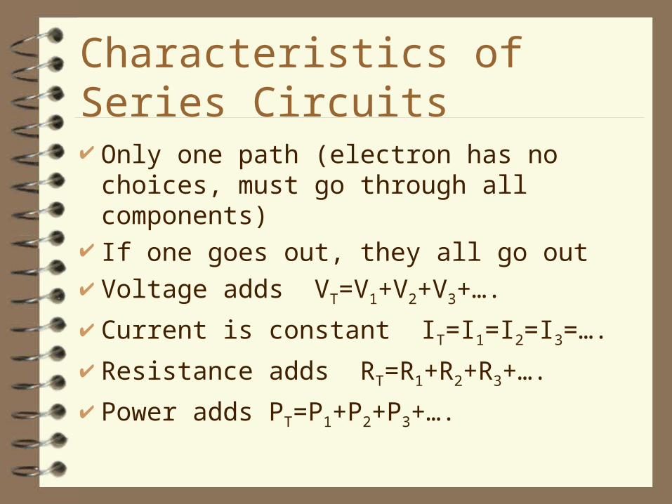
Characteristics of Series Circuits
Only one path (electron has no choices, must go through all components)
If one goes out, they all go out Voltage adds VT=V1+V2+V3+….
Current is constant IT=I1=I2=I3=….
Resistance adds RT=R1+R2+R3+….
Power adds PT=P1+P2+P3+….

Characteristics of Parallel Circuits More than one path Voltage is constant VT=V1=V2=V3=….
Current adds IT=I1+I2+I3+….
Resistance reciprocals add to give the reciprocal
Power adds PT = P1 + P2 + P3 + ……
....1111
321
RRRRT

Solving Problems Set up chart Fill in given information. Fill in what is constant in that type of circuit Look for any place where you either have at
least 2 in a column or all but one in a row. Use Ohm’s law to complete columns and
characteristics of that type of circuit to complete row.
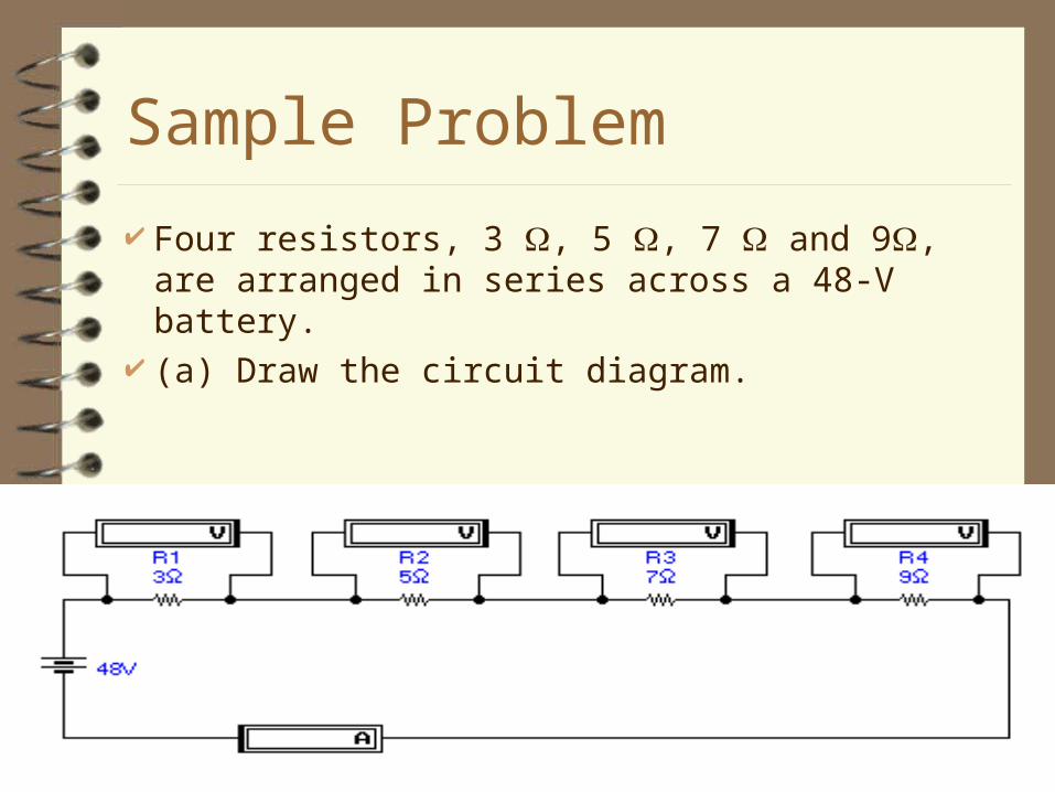
Sample Problem
Four resistors, 3 , 5 , 7 and 9, are arranged in series across a 48-V battery.
(a) Draw the circuit diagram.

Cont’d Find (b) the equivalent resistance and (c)
the current in the circuit. (d) Calculate the voltage drop across each resistor. (e) What power is dissipated in each resistor?
VT = V1 = V2 = V3 = V4 =
IT = I1 = I2 = I3 = I4 =
RT = R1 = R2 = R3 = R4 =
PT = P1 = P2 = P3 = P4 =
48
975324
2
1814106
2222
3628201296
Record Given ValuesYou have all but one in the resistance row, since it is a series circuit, you add to get the total resistance
You have at least 2 in a column, so V=IR
Since it is a series circuit, the current is constantYou now have at least 2 in all remaining columns, so use V=IR
Calculate all the individual powers using P=VI
Double check with the total power…. Power adds to give the total and P = VI

Sample Problem
Connect the same circuit up with the resistors in parallel. (a) Draw the circuit diagram.

Cont’d (b) What is the voltage drop across each
resistor? (c) What is the equivalent resistance? (d) What current flows through each resistor? (e) Calculate the power dissipated by each resistor.
VT = V1 = V2 = V3 = V4 =
IT = I1 = I2 = I3 = I4 =
RT = R1 = R2 = R3 = R4 =
PT = P1 = P2 = P3 = P4 =
48
97531.27
5.3
48484848
6.99.61637.7
2563294617681814
Show all given informationSince it is a parallel circuit, voltage is constantYou have all but one in the resistance row, so the reciprocals add to give the reciprocal of the totalYou have at least 2 in each column so V = IR
Now calculate all of powers using P = VI…… Don’t forget to double check since the individual powers add to give the total

Internal Resistance of a Battery All batteries have internal resistance
because some of the energy must be used to drive the current through the battery itself.
EMF (electromotive force) also known as the open circuit reading is the maximum amount of energy a battery could produce
The VT (terminal voltage) also known as the closed circuit reading is always less than the EMF due to the internal resistance. It is the actual amount used up in the external circuit.

VT = EMF - Iri
IRE = EMF - Iri
VT = Terminal Voltage in Volts
EMF = Electromotive force in Volts
I = Current in Amps ri = Internal resistance
of the battery in Ohms RE = total resistance of
external circuit

Cells in Series
Positive terminal connected to negative terminal of the next battery
EMF adds Current is constant Internal resistance adds Gives you high voltage for short periods of
time

Cells in Parallel
Positive terminal connected to the positive terminal of the next battery
EMF is constant Current adds Reciprocals of internal resistances add to
give the reciprocal of the total Provides energy for a long time
Sample Problem
Three dry cells each have an EMF of 1.5 V and an internal resistance of 0.1 . What is the EMF if these cells are connected in series?
4.5 V What is the internal resistance of the battery?0.3 Ohm What is the line current if this battery is connected
to a 10 Ohm resistor?0.437 Amps What is the terminal voltage of the battery? 4.37 V
Sample Problem
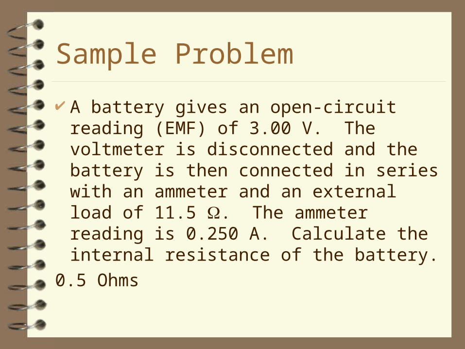
A battery gives an open-circuit reading (EMF) of 3.00 V. The voltmeter is disconnected and the battery is then connected in series with an ammeter and an external load of 11.5 . The ammeter reading is 0.250 A. Calculate the internal resistance of the battery.
0.5 Ohms

Complex Circuits
Also known as combination circuits or networks because parts of the circuit are connected in series and parts in parallel
Create chart… keep simplifying until you have a simple circuit.
Solve using rules for series and parallel

Sample Problem
For each circuit below, determine the readings on each meter. R1 =
10 Ω
R2 = 12 Ω
R3= 6 Ω
R4 = 4 Ω
V1 = 12 V

VT= V1= V2= V3= V4=
IT= I1= I2= I3= I4=
RT= R1= R2= R3= R4=
Record the given information
12
10 12 6 4
2
R2, R3, R4 combine for an equivalent resistance of 2 Ohms since they are in parallel 12
R1 combines with the equivalent resistance of R2, R3, R4 for a combined resistance of 12 Ohms since that is in series
12
1
You have at least 2 in a column so use V=IR
1
The current leaving the battery has no choice but to go through R1. So the current through that resistor is the same as IT
10
You can now play the voltage game. Pick a path that has only one unknown on it such as going through R1 and R2 then back to the battery. The total voltage drop on R1 and R2 must be equal to the terminal voltage of the battery. So the voltage drop across R2 is 2 V
2
Since R3 and R4 are in parallel with R2, the voltage drop across each one must be the same
2 2
0.17 0.33 0.5
You have at least 2 in a column so use V=IR

Kirchhoff’s Laws
1st Law - Total current into a junction is equal to the total current leaving the junction…. Also known as the law of conservation of charge


Sample Problem
Find I4
I4 = ?
I3 = 4 A
1 k
1 k
I2 = 3 A
1 k
I1 = 2 A
1 k
1A
Kirchhoff’s Laws
2nd Law - The algebraic sum of the changes in potential energy occurring in any closed loop is zero due to the law of conservation of energy.

Sign Conventions for 2nd Law
Crossing a resistor with current then -IR Crossing a resistor against current then +IR Crossing a battery with current +V Crossing a battery against current -V

Set it equal to zero, you are back at your starting position. The total change in potential around any closed loop is zero.
Sample Problem
30 Ω
30 V
20 Ω 60 Ω
50 V
5 Ω
I1
I2
I3
Left Clockwise loop starting at A
A
You cross the 20 Ohm resistor against current, so +20I1
20I1
You next cross the 5 Ohm resistor against current so +5I2
+5I2
You next cross the 30 Ohm resistor against current so +30I1
+30I1
You next cross a battery against current so -30
-30 =0

Solving for Currents using K. Laws You must have one first law equation and 2
second law equations. Rearrange equation into proper format. D(I1) + E(I2) + F(I3) = G
Set up matrix A (3 x 3) and B (3x1) A-1B

Sample Problem
30 Ω
30 V
20 Ω 60 Ω
50 V
5 Ω
I1
I2
I3
Left Clockwise Loop Equation:
20I1 +5I2 + 30I1 – 30 =0
Right Clockwise Loop Equation:
50 - 5I2 -60I3 = 0
Bottom junction equation
I1 + I3 = I2

Rearrange all equations to fit the DI1 + EI2 + FI3 = G format
50I1 + 5I2 + 0I3 = 30
0I1 – 5I2 -60I3 = -50
1I1 – 1I2 + 1I3 = 0Create a 3 x 3 matrix named A using the left side of each equation
Matrix A
50 5 0
0 -5 -60
1 -1 1Create a 3 x 1 matrix named B using the right side of each equation
Matrix B
30
-50
0
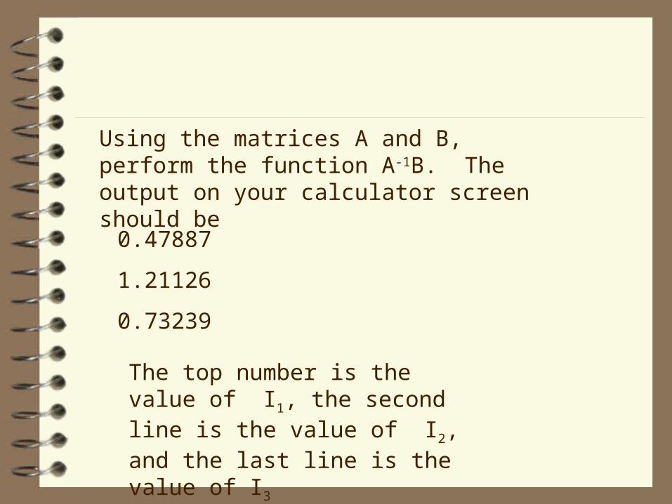
Using the matrices A and B, perform the function A-1B. The output on your calculator screen should be
0.47887
1.21126
0.73239
The top number is the value of I1, the second line is the value of I2, and the last line is the value of I3