Embed Size (px)
Citation preview

SIEMENS c
c
Series 8100oT· Vacuum Controllers
Bulletin CC3802-02 www . El
ectric
alPar
tMan
uals
. com

www . El
ectric
alPar
tMan
uals
. com

Technological Development
Vacuum technology has developed rapidly in recent years and is becoming widely accepted for medium voltage motor control applications, replacing the predominant air break technology. (See Figure 1, Comparison Chart).
The development of the vacuum contactor was a major step forward. Although the basic facts of
FEATURES VACUUM
Extensive and wide-ranging research and development were an essential preliminary to the introduction of high-performance medium voltage vacuum contactors capable otswitching their respective currents reliably and with virtually no maintenance. The rated number of switching operations is so high that the limits are hardly reached in actual practice.
AIR
Continuous Current 360 Amperes 180 or 360 Amperes Voltage Rating SkV SkV Interrupting Rating (Fused) 400mVA 400mVA Electrical Life 1,000,000 Operations 100,000 Operations Mounting Configuration 3-High (600A Max.) 3-High (540A Max.)
Figure 1. Series 81000 Vacuum Versus Air Comparison Chart
current interruption in vacuum were known at the turn of the last century, quantity production of vacuum interrupters waited until it became possible in the mid-sixties to use new technologies and manufacturing methods with economic efficiency. Modern manufacturing and testing methods make it possible to keep the vacuum at such a high level that the full switching capacity of the interrupter is assured even after several years storage.
Contactors for medium voltages should invariably be vacuum type. This design has firmly established itself because of the advantages it offers. Siemens has supplied the 3TL Series of vacuum contactors in large quantities since 1972.
-
www . El
ectric
alPar
tMan
uals
. com
---------------------------
Vacuum Design Criteria • High Reliabillly and Long Service Life • Compact Design and Lighter Weight
-
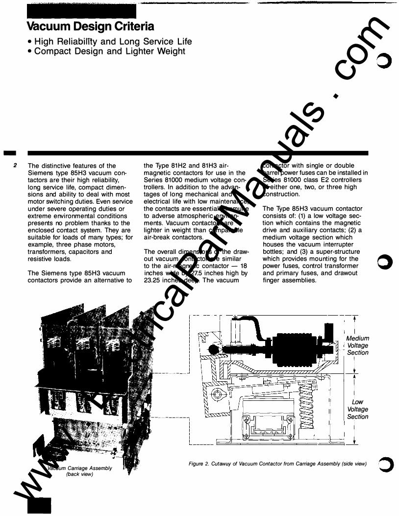
2 The distinctive features of the Siemens type 85H3 vacuum contactors are their high reliability, long service life, compact dimensions and ability to deal with most motor switching duties. Even service under severe operating duties or extreme environmental conditions presents no problem thanks to the enclosed contact system. They are suitable for loads of many types; for example, three phase motors, transformers, capacitors and resistive loads.
The Siemens type 85H3 vacuum contactors provide an alternative to
Vacuum Carriage Assembly (back view)
the Type 81H2 and 81H3 airmagnetic contactors for use in the Series 81000 medium voltage controllers. In addition to the advantages of long mechanical and electrical life with low maintenance, the contacts are essentially immune to adverse atmospheric environments. Vacuum contactors are lighter in weight than comparable air-break contactors.
The overall dimensions of the drawout vacuum contactor are similar to the air-magnetic contactor - 18 inches wide by 27.5 inches high by 23.25 inches deep. The vacuum
contactor with single or double barrel power fuses can be installed in Series 81000 class E2 controllers of either one, two, or three high construction.
The Type 85H3 vacuum contactor consists of: (1) a low voltage section which contains the magnetic drive and auxiliary con tacts; (2) a medium voltage section which houses the vacuum interrupter bottles; and (3) a super-structure which provides mounting for the o power fuses, control transformer and primary fuses, and drawout finger assemblies.
Medium Voltage Section
���-! Low
Voltage -----� Section
l------���-1 Figure 2. Cutaway of Vacuum Contactor from Carriage Assembly (side view)
www . El
ectric
alPar
tMan
uals
. com

Operation and Ratings Data • 5000 Volt Insulation Level • Ratings for Both AC and DC Supply
Operation Since arc interruption is accomplished completely within vacuum bottles, arc chutes, blowout coils and pole plates are not required. Stationary and movable power contacts are located inside the vacuum bottles with corrugated steel spring bellows attached to the movable contacts to insure a complete seal and integrity of the vacuum bottle. Because the contacts are sealed in the interrupter and have only a short travel, it is possible to construct vacuum contactors of a compact size.
Series 81000 class E2 controllers designed for use with vacuum contactors are very similar to those which are used with our air-magnetic contactors. The handle mechanism, line and load power disconnects and line switch interlock (LSI) are identical in both cases. Features unique to our vacuum controllers are a racking mechanism mechanically interlocked by means of a solenoid actuated plunger and, whenever needed surge arrestors furnished to limit transient overvoltages caused by multiple reignitions.
Siemens medium voltage vacuum contactors are built in accordance with the latest applicable provisions of the National Electrical Code (NEC) , Underwriters' Laboratories Standards and Procedures, specifically UL 347, NEMA ICS2-324, VDE and IEC standards, and the National Electrical Safety Code.
Operating Data Ratings The coil ratings are shown in Figure 3 for both AC or DC supply. When individual control power transformers are supplied, the standard size is 0.75kVA with 115
The 85H3 vacuum contactors are NEMA size H3 (360 ampere enclosed) with 5000 volt insulation level. Maximum ratings are shown in Figure 4.
or 230V AC secondary. Note the extreme low seal-in current and low energy consumption of the coil.
Figure3.
OPERATING DATA
DE SCRIPTION
Rated Control Voltage Pick-Up Voltage
Drop-Out Voltage
Pick-Up Time (to contact touch) Drop-Out Time (to contact break) Inrush Current**
Sealing Current**
*Denotes Utilization Voltage. **Maximum, Warm Coil
Figure4.
230VOLT 115VOLT AC SUPPLY* AC SUPPLY*
240Volts 120 Volts
190 Volts 95 Volts
24 Volts 12Volts
5-7 cycles 5-7 cycles
5-7 cycles 5-7 cycles
4.2Amps 8.6Amps
0.43Amps 0.87 Amps
CONTACTOR RATING
250VOLT 125VOLT DC SUPPLY DC SUPPLY
250Volts 125 Volts
200Volts 100 Volts
20Volts 10Volts
5-7 cycles 5-7 cycles
5-7 cycles 5-7 cycles
3.1 Amps 6.0Amps
0.35Amps 0.65Amps
Interrupting Horsepower Rating at Utilization Voltage
Enclosed Capacity Continuous Unfused Fused Ampere ClassE2 Rating 2300- Controllers
5000V JMVA)
360 4.5KA 200@ 2300V
350@4000V
400@4600V
2300V, 3 Phase
Synchronous Induction Motors Motors
0.8PF 1.0PF
1500 1750 1500
4000 & 4600V, 3 Phase
Synchronous Induction Motors Motors
0.8PF 1.0PF
2500 3000 2500
.. Auxiliary Contacts: On drawout contactors, 2 N.O. and 2 N.C. contacts are available for customers use .
These contacts are rated 600V, tOA (NEMA Class A600).
KV Impulse Level (BIL)
60
-
3
www . El
ectric
alPar
tMan
uals
. com

-
4
Isolation Disconnect and Interlocking • Electrical and Mechanical Interlocks • Overvoltage Transients
Mechanical and electrical interlocks - view from inside cubicle (side sheet removed)
Isolation Disconnect The Series 81000 controllers use the complete contactor drawout assembly as the high voltage isolation switch. Horizontal forward and back movement of the drawout assembly simultaneously opens and closes the line and load contacts. Because both line and load terminals are disconnected there is no need for grounding the load side terminals in the open position. Non-conducting glass polyester barriers completely isolate the stationary line terminals. The shutter mechanism is positively driven by the same linkage mechanism which moves the contactor from the connected to the disconnected position.
Interlocking A combination of mechanical and electrical interlocks are included to:
(a) Prevent the forward and back movement of the drawout contactor assembly (isolation switch) unless the contactor is de-energized or open.
(b) Prevent the opening of the high voltage compartment door unless the contactor assembly (isolation switch) is de-energized or open.
(c) Prevent the forward movement of the drawout contactor assembly (isolation switch) to the closed position unless the high voltage compartment door is closed.
Typical isolation disconnect on power module
Overvoltages Due to Current Interruption In Vacuum Of the three major reasons of overvoltage transients due to switching current in vacuum, multiple reignition is the most serious problem. The use of modern contact materials has reduced the chopping current values to a range of 0.5 to 5 amps, hence, overvoltage from current chopping in vacuum is no longer a serious problem as it was once thought to be.
The second area of concern is overvoltage due to virtual current chopping. Protection against over-
www . El
ectric
alPar
tMan
uals
. com

voltages caused by multiple reignition will also provide protection from virtual current chopping. Hence, the major area of concern is multiple reignition which is possible under the following conditions, regardless of the chopping current rating of the vacuum interrupter: a) motor with locked rotor current of 500A or less is switched off under locked rotor condition, that is, while the motor is not fully up to speed yet, such as during startup or jogging conditions. b) the main contacts of the vacuum interrupter parted at an instant of time less than 0.5 milliseconds from the natural sinusoidal zero of current. This condition is possible 18% of the time for a three phase system. c) the natural frequency on the load side of the interrupter is between 0.5 and 5.0 kHz.
N I -"
�
Figure 5. Multiple Reignitions
100 �--------------------�
Region in which multiple 50 reignitions are possible
10
\ c 5
d�' 0.5
b
0.1
10 100 1000 10000
LOCKED-ROTOR CURRENT, amps
Surge arrestors mounted within the controller.
If we examine Figure 5, and the prerequisite conditions for multiple reignition, it can be said that the first condition is a function of the motor size, while the second condition is a probability function, and the third condition is a function of the system, namely the motor inductance and the load cable capacitance. Siemens has developed four tables to determine the maximum length of load cables that will not allow reignition to occur.
These tables (pages 6-7) are published for both shielded and nonshielded cable. If the length of cable from the controller to the motor exceeds the distance shown
on these charts, then surge arrestors should be applied either in the controller or at the motor to prevent the possibility of multiple reignition.
Most medium voltage controllers will not require surge arrestors due to the short length of cable and the size of the motor. However, in applications where reignition is possible, the condition should not be ignored. Zinc oxide varistors can be supplied within the high voltage compartment at a nominal cost without requiring extra space. These arrestors limit the magnitude of the surge to a level generally found in interrupters other than vacuum.
-
5
www . El
ectric
alPar
tMan
uals
. com

-
Surge Arrestors Applications • Shielded Cable
Maximum Length of Load Cables
A 350 hp, 4160 volt motor in a pump station will be located approximately 300 ft. from the controller, using 1/0 shielded cable. Figure 7 shows maximum length at 350 hp to be approximately 230 ft. Therefore, surge arrestors should be applied.
www . El
ectric
alPar
tMan
uals
. com

Surge Arrestors Applications • Nonshielded Cable
Maximum Length of Load Cables
2000 � 1500 � � � 1000 5 � 500
0 0
2000 �1500
v
I � � � 1000
ALL CABLE SIZES-r---.. I [\_ ALL
CABLE SIZES
v L
•
100
5 � 500 l> ,.....
� v
0 500 0 100
A 300 hp, 2300 volt motor in a chemical plant will be located approximately 1000 ft. from the controller using 3/0 non-shielded cable. Figure 8 shows maximum length at 300 hp to be approximately 2000 ft. Therefore, surge arrestors are not required.
-
/ v
500
www . El
ectric
alPar
tMan
uals
. com

Contactor Options • Control Power Transformers • Blown Fuse Trip Bar • Auxiliary Contacts • A NSI "R" Rated Fuses
�
B Control Power Transformers The basic controller includes a 0.75kVA control power transformer as standard mounted on the drawout carriage. Oversize ratings are available up to 3.25kVA. When dual voltage (230/115V) is required, a separate 230-115 volt transformer can be supplied in the low voltage compartment.
Power Fuses ______ ,..
Contactor
CPT Primary Fuse __ _.
Control Power Transrormer-------��
Blown Fuse Trip Bar A blown fuse trip bar can be supplied to open the contactor in the event of a blown fuse. The b contact (NC) will always be in the DC side of the control circuit.
Vacuum Carriage Assembly (front view)
Auxiliary Contacts All contactors are supplied with two NO and two NC extra auxiliary contacts available for customer use. Extra contacts are available through the use of the MR relay or extra control relays.
Power Fuses ANSI "R" rated fuses are furnished for motor starting duty. ANSI "E" rated fuses are used for most other applications. When subjected to high values of fault currents, the � total clearing time of these fuses # will be within the first one-half cycle, and the maximum instantaneous peak current permitted by the largest fuse is 52KA (kiloamperes). Fuses 2R through 12R are single barrel; 18R and 24R are double barrel.
Location of Power Fuses (Air and Vacuum)
Latched Contactors A latched version of the air-break contactors is available for feeder applications. For information or questions on the latched vacuum contactor, refer to the factory.
www . El
ectric
alPar
tMan
uals
. com

Construction Features • Wide Variety of Grouped Assemblies • Power Module for Conversions
Grouped Assemblies Two or more controllers can be grouped into one or more structures 36 inches wide by 36 inches deep by 90 inches high. Typical groups could include Full-Voltage Non-Reversing (FVNR) Induction Starters, Full-Voltage NonReversing Synchronous Starters, Reduced Voltage Reactor or Autotransformer Type Starters, and Transformer Feeders.
LH VERTICAL SUPPORT
Figure 10. Power Module for OEM Units
INSULATING SHEET
Standard vertical structures consist of three 30-inch high cubicles. One, two, or three controllers may be included in one structure. When three controllers are required, the horizontal bus with ground bus, is mounted in a top mounted 10-inch by 36-inch compartment. An option using two 45-inch compartments with top mounted bus is also available.
Tin plated aluminum horizontal power bus is available in 600, 1000, and 1200 ampere ratings. Tin plated or silver plated copper is also available in 1000 to 2000 ampere ratings. The vertical bus is copper only.
When mounting two or three controllers in one vertical structure, the sum of the full load current of the motors should not exceed 600 amperes.
Original Equipment Manufacturer (OEM) Units The power module consists of stabs, shutter, handle, and racking mechanism, and the. drawout contactor. The module shown in Figure 10 shows the racking mechanism (encircled) for the air break contactors; those modules for vacuum contactor include the racking mechanism mechanically interlocked by a solenoid actuated plunger shown on page 4 of this brochure. These power modules are available to OEMs for mounting in cubicles of their design.
Conversion Kits A power module similar to the OEM kit is also available to convert existing Spacemaker II and Series 81000 air-break starters to vacuum starters.
-
9
www . El
ectric
alPar
tMan
uals
. com

SIEMENS
Sales Offices
lrKfiana l;vansville .
(�12) 422·9176 Fort Wayne t2tQ) 744-0440 lndiao•s (31.7) 7$��5500 Roseland (219) 277-7040
wasisslptJi Jack!i>OO (001) 982-2274
Bulletin CC3802-02 (Reprint) Printed in U.S.A. 10M10881PD
· Notthoa�� �riQtte {7!)4)!��6-1201. G�I:ISI:ioro (919). $7;3.1&49
· Ral(ligh {919) 782·3365
lnt.rnational-TLX: $22024SEAII!30 OF FAX: (404) 751�24�
Siemens control products. States, Canada, and in over
Siemens Energy & Automation, Inc.
Controls Division 3333 State Bridge Rd.
:) Alpharetta, GA 30201 (404) 751-2000
··"�
© 1988 Siemens Energy & Automation, Inc. www . El
ectric
alPar
tMan
uals
. com


