Embed Size (px)
Citation preview
- 1 - 100.6605.19
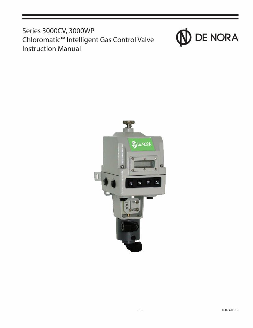
Series 3000CV, 3000WPChloromatic™ Intelligent Gas Control ValveInstruction Manual

100.6605.19 - 2 -
These instructions describe the installation, operation and maintenance of the subject equipment. Failure to strictly follow these instructions can lead to an equipment rupture that may cause significant property damage, severe personal injury and even death. If you do not understand these instructions, please call De Nora Water Technologies (DNWT), Inc. for clarification before commencing any work at +1 215 997 4000 and ask for a Field Service Manager. De Nora Water Technologies, Inc. reserves the rights to make engineering refinements that may not be described herein. It is the responsibility of the installer to contact DNWT Inc. for information that cannot be answered specifically by these instructions.
Any customer request to alter or reduce the design safeguards incorporated into DNWT Inc. equipment is conditioned on the customer absolving DNWT Inc. from any consequences of such a decision.
DNWT Inc. has developed the recommended installation, operating and maintenance procedures with careful attention to safety. In addition to instruction/operating manuals, all instructions given on labels or attached tags should be followed. Regardless of these efforts, it is not possible to eliminate all hazards from the equipment or foresee every possible hazard that may occur. It is the responsibility of the installer to ensure that the recommended installation instructions are followed. It is the responsibility of the user to ensure that the recommended operating and maintenance instructions are followed. De Nora Water Technologies, Inc. cannot be responsible for deviations from the recommended instructions that may result in a hazardous or unsafe condition.
DNWT Inc. cannot be responsible for the overall system design of which our equipment may be an integral part of or any unauthorized modifications to the equipment made by any party other that DNWT Inc.
DNWT Inc. takes all reasonable precautions in packaging the equipment to prevent shipping damage. Carefully inspect each item and report damages immediately to the shipping agent involved for equipment shipped “F.O.B. Colmar” or to DNWT Inc. for equipment shipped “F.O.B Jobsite”. Do not install damaged equipment.
DE NORA WATER TECHNOLOGIES - COLMAR OPERATIONSCOLMAR, PENNSYLVANIA, USAISO 9001: 2008 CERTIFIED
READ THE ENTIRE MANUAL BEFORE OPERATING
USE ONLY IN ACCORDANCE WITH INSTRUCTION MANUAL
WARNING: HAZARDOUS VOLTAGES
PROTECTIVE GROUND (EARTH) TERMINAL
WARNING
FAILURE TO INSTALL, SET UP OR OPERATE THE CHEMICAL INDUCTION UNIT IN THE MANNER SPECIFIED BY De Nora Water Technologies MAY IMPAIR THE
PROTECTION PROVIDED BY THIS EQUIPMENT.

- 3 - 100.6605.19
Table of Contents SAFETY ........................................................................................................................................................................................................................... 5
1 INTRODUCTION .......................................................................................................................................................................................................... 6
2 SPECIFICATIONS .......................................................................................................................................................................................................... 7
3 MODEL NUMBERING ................................................................................................................................................................................................. 9
4 INSTALLATION ............................................................................................................................................................................................................10 4.1 General ............................................................................................................................................................................................................10 4.2 Location ..........................................................................................................................................................................................................10 4.3 Piping ...............................................................................................................................................................................................................10 4.4 Electrical Interconnection ........................................................................................................................................................................11
5 FUNCTIONAL DESCRIPTION .................................................................................................................................................................................15 5.1 Motor Frame & Mechanical Components ..........................................................................................................................................15 5.2 Electronic Circuit Boards ...........................................................................................................................................................................15 5.3 ChloromaticTM 3000 Control Valve Display .........................................................................................................................................16 5.4 Gas Valve.........................................................................................................................................................................................................17
6 SELECTING A CONTROL STRATEGY ....................................................................................................................................................................18 6.1 Flow Pacing ...................................................................................................................................................................................................18 6.2 Residual (Feedback) Control ...................................................................................................................................................................19 6.3 Compound Loop Control .........................................................................................................................................................................20 6.4 Feed Forward Dechlorination or Ammoniation Control ...............................................................................................................20 6.5 Manual Control ............................................................................................................................................................................................21
7 PLACING IN OPERATION .........................................................................................................................................................................................22 7.1 ChloromaticTM 3000 Control Valve Display .........................................................................................................................................22 7.2 Pushbutton Operation ..............................................................................................................................................................................23 7.3 Initial Display Attitude ...............................................................................................................................................................................22 7.4 (1.0) RUN MODE ...........................................................................................................................................................................................24 7.5 (2.0) SET UP .................................................................................................................................................................................................24 7.6 (2.1) CALIBRATION .......................................................................................................................................................................................24 7.7 (2.2) CONTROL SETUP ................................................................................................................................................................................24 7.8 (2.3) CONTACT INPUTS ..............................................................................................................................................................................33 7.9 (2.4) OUTPUT RELAYS .................................................................................................................................................................................34 7.10 (2.5) DEFAULTS ..............................................................................................................................................................................................35 7.11 (3.0) DIAGNOSTICS ......................................................................................................................................................................................36 7.12 (4.0) ALARMS .................................................................................................................................................................................................36
8 PARAMETER DESCRIPTIONS..................................................................................................................................................................................37
8.1 Display Units .................................................................................................................................................................................................37 8.2 Flow Meter Signal ........................................................................................................................................................................................37 8.3 Process Water Flow and Gas Dispenser Output ...............................................................................................................................37 8.4 Damping .................................................................................................................................................................................................37 8.5 Flow Meter Low Alarm ..............................................................................................................................................................................37 8.6 Low Flow Alarm Deadband .....................................................................................................................................................................37 8.7 Lost flow / Gas Feed ...................................................................................................................................................................................37 8.8 Local Ratio Multiplier .................................................................................................................................................................................37 8.9 Remote Ratio Set .........................................................................................................................................................................................38 8.10 Remote Ratio Set Signal ............................................................................................................................................................................38 8.11 Residual Analyzer Signal ...........................................................................................................................................................................38 8.12 Residual Analyzer Max and Min .............................................................................................................................................................38 8.13 Residual Analyzer High and Low Alarm ..............................................................................................................................................38 8.14 Residual Alarm Deadband .......................................................................................................................................................................38 8.15 Reference Set Point ....................................................................................................................................................................................38

100.6605.19 - 4 -
8.16 Residual Proportional Band (gain) ........................................................................................................................................................38 8.17 Controller Tuning ........................................................................................................................................................................................39 8.18 Adaptive Reset .............................................................................................................................................................................................39 8.19 Remote Set Point .........................................................................................................................................................................................40 8.20 Set Point .................................................................................................................................................................................................40 8.21 Remote Set Point Signal ...........................................................................................................................................................................40 8.22 Set Point Deviation Alarm ........................................................................................................................................................................40 8.23 Contact Inputs ..............................................................................................................................................................................................40 8.24 Vacuum Switch Enable ..............................................................................................................................................................................40 8.25 Vacuum Switch Configuration ................................................................................................................................................................40 8.26 Vacuum Switch Fault Action....................................................................................................................................................................40 8.27 Standby Enable ............................................................................................................................................................................................41 8.28 Standby Configuration ..............................................................................................................................................................................41 8.29 Output Relays ...............................................................................................................................................................................................41 8.30 Relay 1, 2, 3 Assignment ...........................................................................................................................................................................41 8.31 Relay 1, 2, 3 Configuration .......................................................................................................................................................................41 8.32 Alarm List .................................................................................................................................................................................................42
9 CALIBRATION .............................................................................................................................................................................................................43
10 MAINTENANCE ..........................................................................................................................................................................................................46 10.1 General ............................................................................................................................................................................................................46 10.2 Shut Down .....................................................................................................................................................................................................46 10.3 Valve Body .................................................................................................................................................................................................46
11 MENU TREE .................................................................................................................................................................................................................51
12 TROUBLESHOOTING THE AUTOMATIC CONTROL VALVE ............................................................................................................................61
FIGURES1 Typical Vacuum Installation ..................................................................................................................................................................................112 Series 3000 ChloromaticTM Valve 500 PPD .......................................................................................................................................................123 Series 3000 ChloromaticTM Valve 1000 - 3000 PPD .......................................................................................................................................134 Wiring Diagram .........................................................................................................................................................................................................145 Series 3000 ChloromaticTM Valve Control Valve Display ..............................................................................................................................166 Typical Valve Plugs 177 Flow Proportioning Control..................................................................................................................................................................................188 Residual (Feedback) Control.................................................................................................................................................................................19 9 Control Process Lagtime ........................................................................................................................................................................................19 10 Compound Loop Control ......................................................................................................................................................................................2011 Feed Forward Control .............................................................................................................................................................................................2112 Series 3000 ChloromaticTM Control Valve Display .........................................................................................................................................2213 Valve Plug ....................................................................................................................................................................................................................4714 Exploded View of 1" Stroke Rate Valve .............................................................................................................................................................4815 Motor Frame Assembly ..........................................................................................................................................................................................4916 Internal Wiring Diagram.........................................................................................................................................................................................50

- 5 - 100.6605.19
SAFETY
Observe the following precautions:
Observe all safety warnings as noted in this manual and marked on the equipment. These warnings identify areas of immediate hazard which could result in personal injury or loss of life.
Do not remove or obscure warning and caution labels.
Read and understand all warning and caution labels.
Do not use this equipment for any purpose other than described in this instruction manual. Use all practical safety precautions to prevent contact with energized parts of the equipment and related circuits.
Use the recommended connection procedures described elsewhere in this manual.
DNWT Inc. recommends that qualified personnel install and connect this equipment. Component replacement and internal adjustments must be made by qualified service personnel.
The following warning and caution notices are used in this manual where applicable and should be strictly observed.
WARNINGWarning, as used in this manual, is defined as a condition or practice which could
result in personal injury or loss of life.
CAUTIONCaution, as used in this manual, is defined as a condition or practice
which could result in damage to or destruction of this equipment.
The Chlorine Institute offers a series of free pamphlets concerned with the safe hangling of chlorine gas. These pamphlets may be downloaded from their website at www.chlorineinstitute.org.

100.6605.19 - 6 -
1 INTRODUCTIONThe information in this document should be completely reviewed and understood before starting up the equipment. This manual documents the installation, control strategies and parameter settings used by the Capital Controls® Series 3000 ChloromaticTM Valve.
The Chloromatic™ Valve Series 3000 operates at sonic conditions for the ten operating ranges from 10 PPD (0.5 kg/h) to 3000 PPD (60 kg/h). A D/P regulator is not required to maintain a constant feed rate with varying vacuum fluctuations.
The Chloromatic Valve microprocessor-based controller contains specifically designed control logic used to control the chlorination, dechlorination, ammonia and carbon dioxide processes. The programming for four strategies described in Section 6 is installed at the factory to assure easy start-up. You need only initialize the controller, select the strategy appropriate for your site, and enter custom values for the operating parameters. All strategies include a multi-stage alarm system to alert operators to conditions, which are above or below the desired levels.
The Chloromatic Valve controller features an easy-to-read vacuum fluorescent display which provides all data necessary for proper operation. Both the display and the pushbuttons, used to cycle through the displays and to enter new values for parameters, are conveniently located on the front of the operator.
The Chloromatic Valve controller receives external analog signals from a flowmeter transmitter and/or a residual chlorine analyzer, and adjusts the valve position in accordance with the chosen strategy.
In the most sophisticated of control strategies discussed later, the controller will digitally compare measured residual with an operator-selected set point, multiply this value by the process water flow rate signal, and adjust the valve plug accordingly. The PI control function features an adjustable proportional band, a reset time and an adaptive reset mode to fine-tune the process.
The Chloromatic Valve may be operated in either automatic or manual mode.
A unique valve plug profiling feature allows for a true gas flow retransmission signal to be sent to a recorder of SCADA system.
- 7 - 100.6605.19
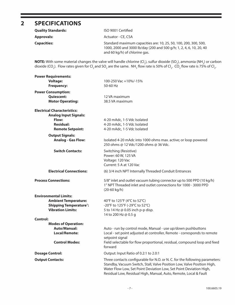
2 SPECIFICATIONS Quality Standards: ISO 9001 Certified
Approvals: Actuator - CE, CSA
Capacities: Standard maximum capacities are: 10, 25, 50, 100, 200, 300, 500, 1000, 2000 and 3000 lb/day (200 and 500 g/h; 1, 2, 4, 6, 10, 20, 40 and 60 kg/h) of chlorine gas.
NOTE: With some material changes the valve will handle chlorine (Cl2), sulfur dioxide (SO2), ammonia (NH3) or carbon dioxide (CO2). Flow rates given for Cl2 and SO2 are the same. NH3 flow rate is 50% of Cl2. CO2 flow rate is 75% of Cl2.
Power Requirements: Voltage: 100-250 Vac +10%/-15% Frequency: 50-60 Hz
Power Consumption: Quiescent: 12 VA maximum Motor Operating: 38.5 VA maximum
Electrical Characteristics: Analog Input Signals: Flow: 4-20 mAdc, 1-5 Vdc Isolated Residual: 4-20 mAdc, 1-5 Vdc Isolated Remote Setpoint: 4-20 mAdc, 1-5 Vdc Isolated
Output Signals: Analog - Gas Flow: Isolated 4-20 mAdc into 1000 ohms max. active; or loop powered 250 ohms @ 12 Vdc/1200 ohms @ 36 Vdc.
Switch Contacts: Switching (Resistive) Power: 60 W, 125 VA Voltage: 120 Vac Current: 5 A at 120 Vac
Electrical Connections: (6) 3/4 inch NPT Internally Threaded Conduit Entrances
Process Connections: 5/8" inlet and outlet vacuum tubing connector up to 500 PPD (10 kg/h) 1" NPT Threaded inlet and outlet connections for 1000 - 3000 PPD (20-60 kg/h)
Environmental Limits: Ambient Temperature: 40°F to 125°F (4°C to 52°C) Shipping Temperature1: -20°F to 125°F (-29°C to 52°C) Vibration Limits: 5 to 14 Hz @ 0.05 inch p-p disp. 14 to 200 Hz @ 0.5 g Control:
Modes of Operation: Auto/Manual: Auto - run by control mode, Manual - use up/down pushbuttons Local/Remote: Local - set point adjusted at controller, Remote - corresponds to remote
setpoint signal Control Modes: Field selectable for flow proportional, residual, compound loop and feed
forward
Dosage Control: Output: Input Ratio of 0.2:1 to 2.0:1
Output Contacts: Three contacts configurable for N.O. or N. C. for the following parameters: Standby, Vacuum Switch, Stall, Valve Position Low, Valve Position High, Water Flow Low, Set Point Deviation Low, Set Point Deviation High, Residual Low, Residual High, Manual, Auto, Remote, Local & Fault

100.6605.19 - 8 -
Input Contacts: Two contacts selectable for either Operate/Standby or Vacuum Switch actuation
Manual Override: Manual Control Knob (multi-turn) provided to position valve plug when dosage control is in "off" position or if power fails.
Physical Characteristics Outline Dimension: Approx. 16 inch H x 3/4 inch W x 8 inch D (41 cm H x 20 cm W x 21 cm D) Weight: 15 lb. (6.8 kg) Enclosure Classification: NEMA 4X, IP66 (Self Certified)
Display: Vacuum fluorescent , 2 lines, 16 characters Materials of Construction:
Main Housing & Cover: Die cast aluminum with fusion bonded epoxy powder coat
Valve Plug: Silver, PVC or Austenitic Stainless Steel (capacity and gas type dependent)
Orifice: Fluorosint (Mica filled Teflon)
Cl2 Flow Capacities: 0-10 to 0-3000 lb/d, 0-200 g/h to 0-60 kg/h
Flow Ranges: See Section 3 model numbering, for specific ranges
1 If valve is subject to shipping temperature in excess of 125°F, the PVC valve body screws must be retightened.
- 9 - 100.6605.19
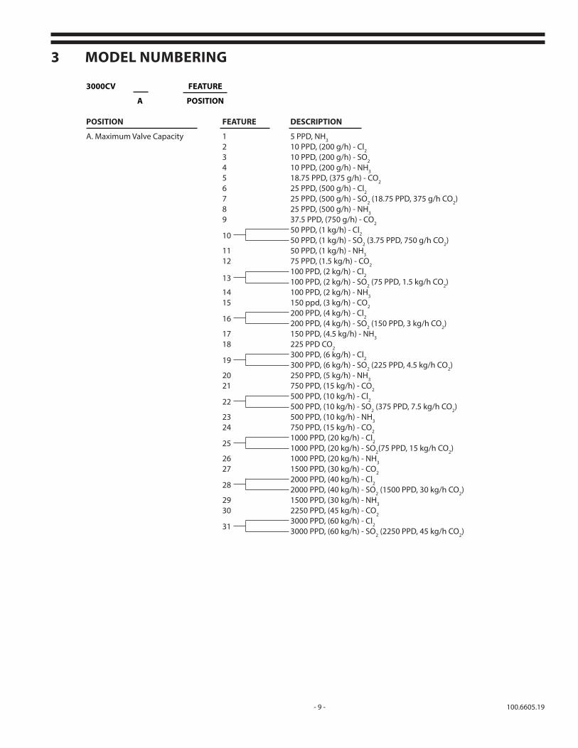
3 MODEL NUMBERING
3000CV FEATURE
A POSITION POSITION FEATURE DESCRIPTION
A. Maximum Valve Capacity 1 5 PPD, NH3
2 10 PPD, (200 g/h) - Cl2 3 10 PPD, (200 g/h) - SO2 4 10 PPD, (200 g/h) - NH3
5 18.75 PPD, (375 g/h) - CO2 6 25 PPD, (500 g/h) - Cl2
7 25 PPD, (500 g/h) - SO2 (18.75 PPD, 375 g/h CO2) 8 25 PPD, (500 g/h) - NH3
9 37.5 PPD, (750 g/h) - CO2
10
50 PPD, (1 kg/h) - Cl2
50 PPD, (1 kg/h) - SO2 (3.75 PPD, 750 g/h CO2) 11 50 PPD, (1 kg/h) - NH3
12 75 PPD, (1.5 kg/h) - CO2
13
100 PPD, (2 kg/h) - Cl2
100 PPD, (2 kg/h) - SO2 (75 PPD, 1.5 kg/h CO2) 14 100 PPD, (2 kg/h) - NH3
15 150 ppd, (3 kg/h) - CO2
16
200 PPD, (4 kg/h) - Cl2
200 PPD, (4 kg/h) - SO2 (150 PPD, 3 kg/h CO2) 17 150 PPD, (4.5 kg/h) - NH3
18 225 PPD CO2
19
300 PPD, (6 kg/h) - Cl2
300 PPD, (6 kg/h) - SO2 (225 PPD, 4.5 kg/h CO2) 20 250 PPD, (5 kg/h) - NH3
21 750 PPD, (15 kg/h) - CO2
22
500 PPD, (10 kg/h) - Cl2
500 PPD, (10 kg/h) - SO2 (375 PPD, 7.5 kg/h CO2) 23 500 PPD, (10 kg/h) - NH3
24 750 PPD, (15 kg/h) - CO2
25
1000 PPD, (20 kg/h) - Cl2
1000 PPD, (20 kg/h) - SO2(75 PPD, 15 kg/h CO2) 26 1000 PPD, (20 kg/h) - NH3 27 1500 PPD, (30 kg/h) - CO2
28
2000 PPD, (40 kg/h) - Cl2
2000 PPD, (40 kg/h) - SO2 (1500 PPD, 30 kg/h CO2) 29 1500 PPD, (30 kg/h) - NH3
30 2250 PPD, (45 kg/h) - CO2
31
3000 PPD, (60 kg/h) - Cl2
3000 PPD, (60 kg/h) - SO2 (2250 PPD, 45 kg/h CO2)

100.6605.19 - 10 -
4 INSTALLATION 4.1 General
The Series 3000 Chloromatic™ Valve is used in a wall mounted vacuum configuration when used in a Series 300 or 200 Series Gas Feed system.
Inspect the parts carefully for indications of damage that may have occurred during shipment. All damage claims should be reported promptly to the shipping agent involved. If damage is such that faulty operation could result, it should be brought to the attention of the De Nora Water Technologies Service Department.
4.2 LocationThe 3000 valve is designed for wall mounting and is to be located between the flow indicator and the ejector.
The installation may be either indoors and outdoors as long as the ambient temperature is within 40 and 125°F (4 and 52°C). If the temperature during shipment exceeded 125°F (52°C), be sure to retighten the valve body screws. Also, to prevent the entry of water, make sure that the cover screws are tight after the electrical connections are completed.
Note: The Chloromatic Valve can be mounted vertically with either the motor operator above or below the valve. The factory default condition is with the motor operator above the valve. Section 7.3 contains instructions to allow the indication and push button functions to be flipped to allow easy viewing and button operation in either position.
4.3 Piping4.3.1 Vacuum Service
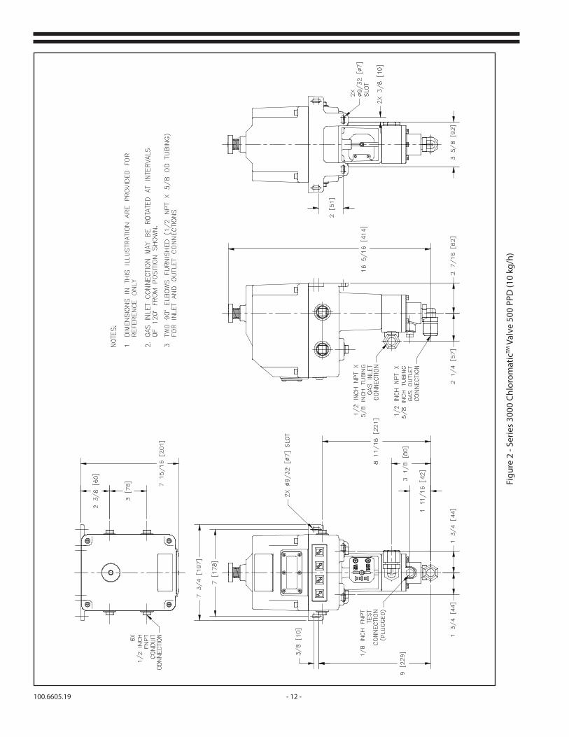
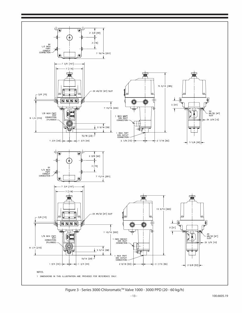
The 3000 valve has 1/2" NPT inlet and outlet connections in the PVC body for capacities up to 500 PPD (10 kg/h). The Valve is furnished with two 90° 1/2" NPT x 5/8" tubing elbows. 5/8" flexible tubing (5/8" OD x 1/2" ID) should be used to make the connections. One (1) inch NPT threaded inlet and outlet connections are provided for 1000 - 3000 PPD (20 - 60 kg/h) capacities. As shown in Figure 1, connect a line from the flowmeter outlet to the valve inlet (side of the valve). Connect the valve outlet (bottom of the valve) to the ejector inlet. If necessary, the valve body can be rotated 120° so that the outlet faces right or left rather than forward, as shipped. To rotate the body, remove the three body screws; rotate the body and retighten the screws securely.
CAUTION:Plastic pipe or tubing connectors may be broken or
damaged if excess torque is used in tightening the fitting. Hand tighten only.
The overall length and size of the interconnecting tubing may be a limiting factor. Refer to Technical Bulletin 121.3003 for details. The 1/4 inch NPT plugged connection in the valve body permits connection of a test gauge to read the vacuum on the downstream side of the valve.
NOTE:All plastic to plastic pipe joints must be lubricated to
prevent galling of the threads, provide a good seal and permit ease of disassembly. The only recommended
sealant/lubricant is Teflon tape.

- 11 - 100.6605.19
Figure 1 - Typical Vacuum Installation
4.4 Electrical 4.4.1 General
Power and signal lines should be run separately. Power and signal terminations are as shown in Figure 4. The branch circuit should be protected by a fuse or circuit breaker and contain a disconnect switch.
The black wire should be the phase side of the line and connect to terminal (L). The neutral or white wire to terminal (N). The case of the actuator must be connected to a bonded earth ground. A ground screw is provided on the bottom of the housing. All wiring should comply with local codes.
Six 3/4" NPT conduit entrances are provided to allow for ease of field installation. Two temporary plastic conduit plugs are provided to maintain closure integrity during shipment and must be discarded at the time of valve installation. If alternate conduit entrances are chosen, the metallic conduit plugs must be moved to the unused conduit entrances using Teflon tape.
4.4.2 Input Signal(s)The Chloromatic Valve can accept either one or two process variable inputs as well as a remote setpoint signal.
The valve accepts signals of 4-20 mAdc or 1-5 Vdc as configured by the user. Each signal can be individually configured.
100.6605.19 - 12 -
Figu
re 2
- Se
ries
3000
Chl
orom
atic
TM V
alve
500
PPD
(10
kg/h
)
- 13 - 100.6605.19
Figure 3 - Series 3000 ChloromaticTM Valve 1000 - 3000 PPD (20 - 60 kg/h)

100.6605.19 - 14 -
Figure 4 - Wiring Diagrams
INPUT 1+ - + -
INPUT 2+ -
INPUT 3 XMT- +
SWITCH 1 SWITCH 2
RELAY
3R
ELAY 2
RELAY
1
3 N.C.
3 N.O.
3 COM.
2 N.C.
2 N.O.
2 COM.
1 N.C.
1 N.O.
1 COM.
OUTPUTRELAYS
+ - + - + -
PROCESSFLOW RESIDUAL POINT
SETREMOTE
GASFLOW SWITCH SWITCH
BYSTAND
VACUUM
INPUTSCONTACT
- +
MAIN BOARD
LOCATEDON
L
N
G
INPUTPOWER
100-250 V47/66 HZ
L
N
LOOP INT
is provided on the bottom of the housing. All wiring shouldconnected to a bonded earth ground. A ground screwGROUNDING: The case of the actuator must be
comply with local codes.
FLOWS1
A B
RESIDUALS2
A B
RSPS3
A B
POSITION A - 1-5 VdcPOSITION B - 4-20 mAdc
S4
SIGNALSINPUT
SIGNALOUTPUT
(NOTE 1) (NOTE 2)
(NOTE 3)
Maximum Load Impedance:1000 ohms
4-20mA Output Wiring Configurations
ACTIVE
-
+
+12 - 36VDC
Maximum Load Impedance:250 ohms @ 12Vdc/1200 ohms @ 36Vdc
Loop Powered- +
-
NOTES:
1. Inputs 1, 2 and 3 are preset for 4-20mA but may be changed to 1 - 5V operation via switches S1, S2 and S3 respectively. 2. Isolated 4-20 mA position transmitter is preset as internally powered but may be reconfigured for loop power via switch S4 Refer to inset for correct wiring in each case. 3. RELAY CONTACTS: Rated at 5 amps, 120 Vac, or 30 Vdc. Refer to instruction manual for configuration via HMI.XMT
INT-
XMTINT+
XMTLOOP+
XMT LOOP-

- 15 - 100.6605.19
5 FUNCTIONAL DESCRIPTION The 3000 valve consists of four basic components: 1. The motor frame or mechanical parts 2. The electronic circuit boards 3. Display and push buttons 4. The gas valve
5.1 Motor Frame and Mechanical ComponentsThe motor drive assembly uses a permanent magnet type stepping motor with a hollow shaft machined to accept a threaded lead screw. The lead screw is restrained from rotating and thus produces a straight line motion when the motor runs. The lead screw is attached to and directly drives the characterized valve plug to regulate the precise flow rate of gas through the valve. Approximately 3200 steps will move the valve plug 1" of travel for precise finite control with minimum over travel.
The housing and cover are powder coated die cast aluminum and fully gasketed. Spring loaded shaft seals are provided where the lead screw exits the electronic area. Six 3/4 inch NPT conduit entrances are provided for power and signal wiring. Pipe plugs are provided to seal the unused entrances.
NOTE: The two plastic plugs are shipping plugs only and are not meant for installation.
A multi-turn feedback potentiometer is gear driven by a pinion gear attached to the motor shaft. The position of the potentiometer has been factory synchronized with the lead screw position to prevent over travel.
5.2 Electronic Circuit Boards 5.2.1 Power Supply Board The power supply board is housed within the enclosure on the motor frame described above.
5.2.2 Main Circuit BoardThe main circuit board is microprocessor-based and contains the needed algorithms required for various control strategies used in water and wastewater disinfection. Depending on the control strategy chosen, it will compare the field process conditions to user settings and move the valve plug accordingly.
The main circuit board also has the capability of an eleven point calibration to accurately match the valve position to the actual flowmeter indication on the gas feeder. This feature automatically yields a true retransmitted gas flow measurement to remote monitoring instruments such as a recorder or SCADA system without the need for limited range auxiliary differential pressure metering devices.

100.6605.19 - 16 -
5.3 3000 Control Valve DisplayThe upper left corner shows the operational status:A AutomaticM ManualU Update in progress
The lower left corner will show a bell symbol when an alarm condition occurs.
The upper line of the display indicates the parameter being viewed.
The lower line indicates the value or nomenclature of the viewed parameter.
The 3000 valve has the capability of being mounted with the valve body below or above the operator and the display can be adjusted to match the orientation.
5.3.1 PushbuttonsThe control valve menus are set up in a tiered fashion. Depressing the “M” (Mode) key will allow access to the next highest tier level. Depressing the “U” (Up) or “D” (Down) keys will allow scrolling through the menu items within each tier level. Depressing “E” (Enter) at the menu items shown on the display will allow access into the next lowest tier level or allow configuration of a particular data point. Section 7 discusses the detailed pushbutton operation.
5.3.2 Input Signal Selector SwitchesRefer to Figure 4. The flow, residual and remote setpoint signals can be either 4-20 mAdc or 1-5 Vdc. Switches S1, S2 & S3 are used to choose the appropriate input signal type.
Figure 5 - Series 3000
Control Valve Display

- 17 - 100.6605.19
5.4 Gas ValveThe gas valve (rate valve) consists of the body, cover, orifice, and valve plug. The details of the valve are shown in Figure 6, an exploded view. The orifice is clamped between the body and cover. The valve plug is a cylindrical body with a flat taper machined into the side of the cylinder, as shown in Figure 6. The face of the taper is machined such that it will produce a flow that is linear with the valve stroke. The valve plug enters the valve body through a spring loaded Teflon shaft seal.
Figure 6 - Gas Valve
NOTE: CSA Certification does not include the valve proper.
100.6605.19 - 18 -
6 SELECTING A CONTROL STRATEGYOnce you have installed the hardware as described in the other instruction bulletins associated with the system you have purchased, and have powered the 3000 valves as described in Section 4, you are ready to select a control strategy. This section provides descriptions of the four available strategies in Sections 6.1 through 6.5 below. • Flow Pacing - Section 6.1
• Residual Control (Feedback Dechlor) - Section 6.2 • Flow Pacing with Residual Control - Section 6.3 • Feed Forward Dechlor - Section 6.4 • Manual Control - Section 6.5
Once you have decided on the strategy to use, follow the instructions in Section 7 to select the strategy. Then determine your custom parameter values for the strategy. Custom parameters for the four strategies are identified in the sections devoted to the strategies.
The parameters set for one control strategy will carry over to another chosen strategy containing the same parameter variables. e.g. Parameters entered for the flow pacing strategy will remain should the compound loop strategy be chosen.
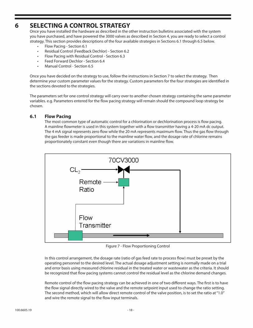
6.1 Flow PacingThe most common type of automatic control for a chlorination or dechlorination process is flow pacing. A mainline flowmeter is used in this system together with a flow transmitter having a 4-20 mA dc output. The 4 mA signal represents zero flow while the 20 mA represents maximum flow. Thus the gas flow through the gas feeder is made proportional to the mainline water flow, and the dosage rate of chlorine remains proportionately constant even though there are variations in mainline flow.
In this control arrangement, the dosage rate (ratio of gas feed rate to process flow) must be preset by the operating personnel to the desired level. The actual dosage adjustment setting is normally made on a trial and error basis using measured chlorine residual in the treated water or wastewater as the criteria. It should be recognized that flow pacing systems cannot control the residual level as the chlorine demand changes.
Remote control of the flow pacing strategy can be achieved in one of two different ways. The first is to have the flow signal directly wired to the valve and the remote setpoint input used to change the ratio setting. The second method, which will allow direct remote control of the valve position, is to set the ratio at “1.0” and wire the remote signal to the flow input terminals.
Figure 7 - Flow Proportioning Control

- 19 - 100.6605.19
A feed rate low limit can be placed on the 3000 valve that will drive the valve to a predetermined level should the flowmeter signal fail. Noting the minimum feed rate over a twenty-four hour period provides a reasonable initial estimate of the low limit setting.
6.2 Residual (Feedback) ControlIn this approach, a chlorine or sulfite residual analyzer is used, taking a sample of the chlorinated water at a point downstream from where chlorine or sulfur dioxide is applied. While at first glance the Residual Only Control approach would seem to solve the problems of both varying mainline flow rate and chlorine demand changes in the water, further study will reveal that this approach is an insensitive system from the point of view of time. Its response to changes in flow is adequate only if changes in flow are slow. However, should flows change quickly, the system will be without knowledge of the change for whatever system lag time exists. During this time there will occur either under or over chlorination; both of which are undesirable. Therefore, in situations where flow changes may be rapid, Flow Paced, Residual Trimmed Control should be used.
Figure 8 - Residual (Feedback) Control
Figure 9 - Control Process Lagtime
Residual control requires the entry of the system integral time. Integral time should be kept in the three to five minute range (for raw water or waste-water), and two to three minutes for finished water if the best control is to be attained. Times longer than these will decrease the precision of control. Shorter times can cause instability in the control system. The system integral time (lag time, reset time) is made up of several small time elements, the major ones being:
A. Time required for the chlorine solution to travel from the ejector to the point of application (t1). This time is usually a constant as the water flow through an ejector is constant. B. Time required for the chlorinated water to travel from the chlorine solution diffuser to the sampling point (leading to the residual analyzer) (t2). This time is a variable dependent on the process flow rate. C. Time required for the sample to travel from the sampling point in the process to the Analyzer. This time element is a constant, once the analyzer has been set up (t3). D. Time required for the analyzer to process the residual change (t4).
100.6605.19 - 20 -
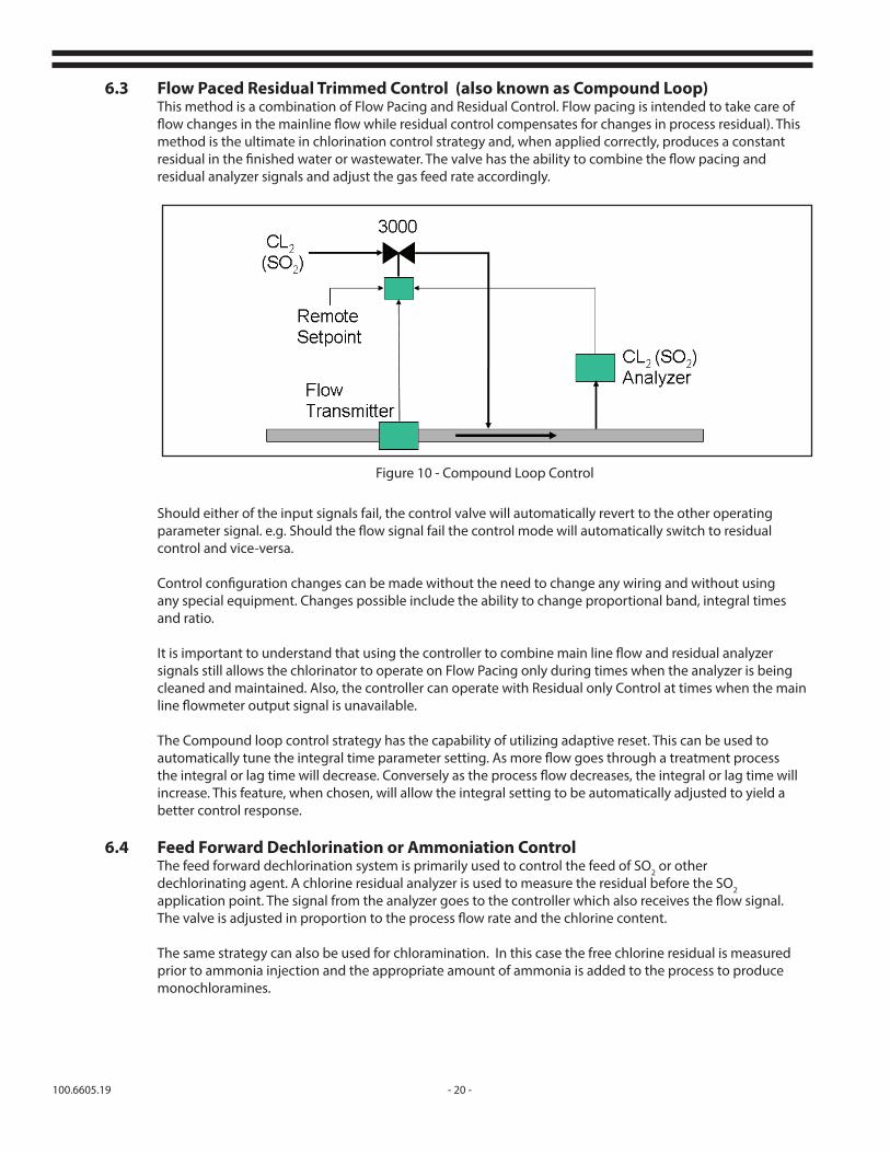
6.3 Flow Paced Residual Trimmed Control (also known as Compound Loop)This method is a combination of Flow Pacing and Residual Control. Flow pacing is intended to take care of flow changes in the mainline flow while residual control compensates for changes in process residual). This method is the ultimate in chlorination control strategy and, when applied correctly, produces a constant residual in the finished water or wastewater. The valve has the ability to combine the flow pacing and residual analyzer signals and adjust the gas feed rate accordingly.
Should either of the input signals fail, the control valve will automatically revert to the other operating parameter signal. e.g. Should the flow signal fail the control mode will automatically switch to residual control and vice-versa.
Control configuration changes can be made without the need to change any wiring and without using any special equipment. Changes possible include the ability to change proportional band, integral times and ratio.
It is important to understand that using the controller to combine main line flow and residual analyzer signals still allows the chlorinator to operate on Flow Pacing only during times when the analyzer is being cleaned and maintained. Also, the controller can operate with Residual only Control at times when the main line flowmeter output signal is unavailable.
The Compound loop control strategy has the capability of utilizing adaptive reset. This can be used to automatically tune the integral time parameter setting. As more flow goes through a treatment process the integral or lag time will decrease. Conversely as the process flow decreases, the integral or lag time will increase. This feature, when chosen, will allow the integral setting to be automatically adjusted to yield a better control response.
6.4 Feed Forward Dechlorination or Ammoniation ControlThe feed forward dechlorination system is primarily used to control the feed of SO2 or other dechlorinating agent. A chlorine residual analyzer is used to measure the residual before the SO2 application point. The signal from the analyzer goes to the controller which also receives the flow signal. The valve is adjusted in proportion to the process flow rate and the chlorine content.
The same strategy can also be used for chloramination. In this case the free chlorine residual is measured prior to ammonia injection and the appropriate amount of ammonia is added to the process to produce monochloramines.
Figure 10 - Compound Loop Control

- 21 - 100.6605.19
Figure 11 - Feed Forward Control
This control strategy combines the scheme of flow pacing combined with a setpoint deviation multiplier. A reference residual set point is entered as the desired residual. The residual analyzer signal is compared to this set point and a multiplication factor applied to the difference between the two. The flow and deviation calculations are then combined to adjust the valve accordingly. A feed rate low limit can be placed on the 3000 valve that will drive the valve to a predetermined level should the flowmeter signal fail. Noting the minimum feed rate over a twenty-four hour period provides a reasonable initial estimate of the valve low limit setting.
6.5 Manual ControlThe valve may be operated in manual mode at any time by going to the RUN MODE menu for the current control strategy and changing the control from automatic to manual. Refer to the appropriate RUN MODE menu string for the chosen control mode in Section 7.0.
100.6605.19 - 22 -
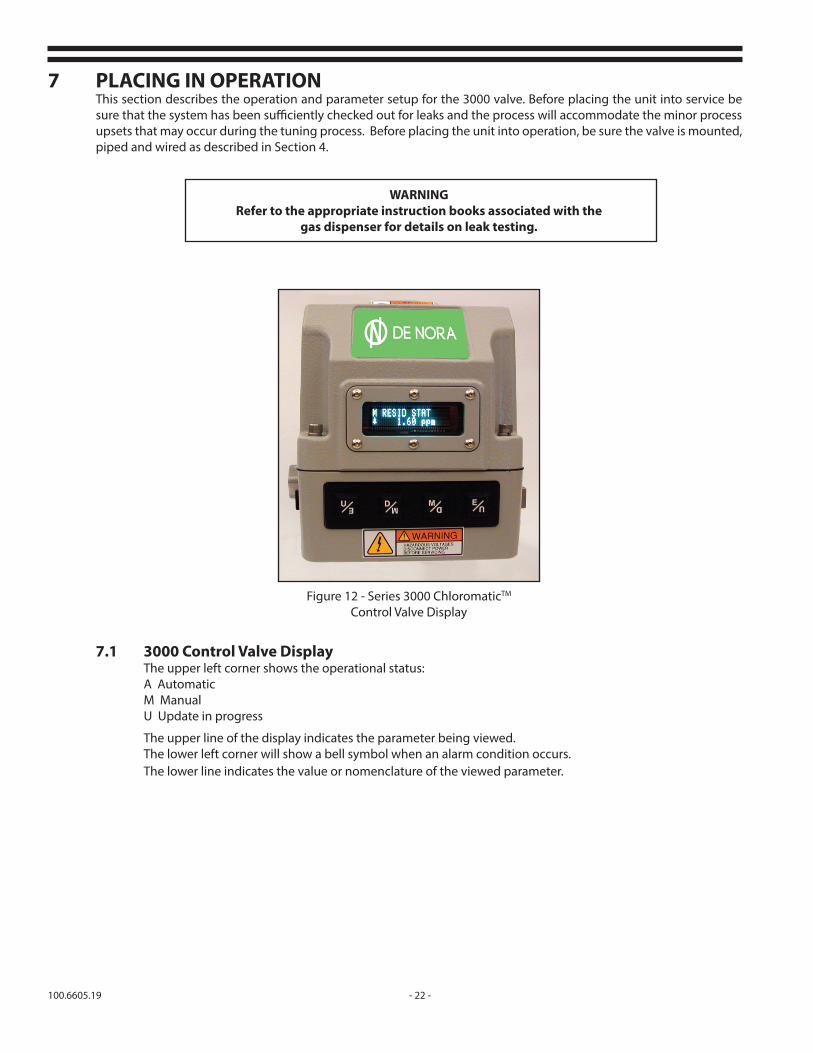
7 PLACING IN OPERATIONThis section describes the operation and parameter setup for the 3000 valve. Before placing the unit into service be sure that the system has been sufficiently checked out for leaks and the process will accommodate the minor process upsets that may occur during the tuning process. Before placing the unit into operation, be sure the valve is mounted, piped and wired as described in Section 4.
WARNINGRefer to the appropriate instruction books associated with the
gas dispenser for details on leak testing.
Figure 12 - Series 3000 ChloromaticTM
Control Valve Display
7.1 3000 Control Valve DisplayThe upper left corner shows the operational status:A AutomaticM ManualU Update in progress
The upper line of the display indicates the parameter being viewed.The lower left corner will show a bell symbol when an alarm condition occurs.The lower line indicates the value or nomenclature of the viewed parameter.

- 23 - 100.6605.19
Top Tier Display String Function
2nd Tier
1.0 RUN MODE Allows viewing controller and process operational conditions
2.0 SET UP Allows entry into the configuration tier of the Chloromatic 3000 Control Valve
2.1 CALIBRATION Allows valve calibration (See section 9.0)
2.2 CONTROL SETUP Allows configuration of the control functions and process parameters (See sections 6.0, 7.0 & 8.0)
2.3 CONTACT INPUT Allows assignment and configuration of the input contacts (See sections 7.9 & 8.23)
2.4 OUTPUT RELAYS Allows assignment and configuration of the output relay contacts (See sections 7.10 & 8.29)
2.5 DEFAULTS Allows resetting of defaults, setting password and inverting the display (See section 7.3 & 7.11)
3.0 DIAGNOSTICS Allows viewing the software and hardware operational conditions (See section 7.12)
4.0 ALARMS Allows viewing of all active alarms
Table A - Top Tier Menu
7.2 Pushbutton OperationThe control valve menus are set up in a tiered fashion. Depressing the “M” (Mode) key will allow access to the next highest tier level. Depressing the “U” (Up) or “D” (Down) keys will allow scrolling through the menu items within the chosen tier level. Depressing “E” (Enter) at the menu items shown on the display will allow access into the next lowest tier level or allow configuration of a particular data point. The display will show SAVED after pressing the “E” key when a parameter or value change has been executed. The top two tier levels are shown in Table A.
NOTE: Initiating changes to the valve when it is in automatic mode will automatically suspend the valve’s operation and hold it in its last position. The valve can then be returned to automatic mode after the changes have been made.
7.3 Initial Display AttitudeNOTE: The 3000 valve has the capability of being mounted with the valve body below or above the operator and the display can be adjusted to match the orientation. The valve is configured at the factory with the operator above the valve. If the valve is to be mounted with the valve body over the operator, the display should be inverted to allow for viewing ease.
To invert the display:Depress the M key to get to the top tier menu. Using the U, D keys scroll to SET UP. Press the E key. Using the U, D keys scroll to DEFAULTS. Press the E key. Using the U, D keys scroll to INVERT DISPLAY. Press E key.Using U, D Keys, scroll to YES. Depress the E key.The display will now be inverted and the pushbuttons will be properly aligned for the chosen mounting attitude.Depress the M key several times to return to the top tier menu. The following paragraphs are indexed ( ) to the menu trees shown within each applicable paragraph and the complete menu tree shown in Section 11.

100.6605.19 - 24 -
7.4 (1.0) RUN MODEEntering RUN MODE and scrolling through the menu will display the particular operational functions and parameters of the chosen control scheme. Certain upper level parameters may be changed from this tier level without the need for entering the 2.2 CONTROL SETUP procedure. The RUN MODE menu for each particular control scheme is shown within the pertinent section of this manual.
7.5 (2.0) SET UP Refer to Table A, shown in Section 7.2, for the five options available in this mode.
To enter SET UP mode:Continuously depress the M key until there is no display change Depress either the U or D keys until SET UP appearsDepress the E keyDepress either the U or D keys until your choice of the five options shown in Table A appears Depress the E key and proceed as indicated in the sections below.
7.6 (2.1) CALIBRATIONUnless specially ordered, the 3000 valve is shipped with a five point calibration at 0, 25, 50, 75 and 100% of scale. The valve has the capability of an eleven point calibration to accurately match the valve position to the actual gas flow as indicated on the gas flow meter of the gas feeder. This allows for an accurate retransmission signal of the gas flow rate to a remote monitoring system without the need for differential type transmitters with limited rangeability. Proceed to Section 7.7 CONTROL SETUP if the factory five point calibration is satisfactory for your purposes. If a tighter calibration is required, proceed to Section 9 Calibration for further details.
7.7 (2.2) CONTROL SETUPPressing the E key when CONTROL SETUP appears on the display allows choosing one of the four control modes. To choose the desired control mode depress the U or D keys and press the E key when the desired control mode is displayed.The control mode choices are:
2.2.1 FLOW PACE2.2.2 FEED FORWARD control2.2.3 COMPOUND loop control2.2.4 RESIDUAL control
After depressing the E key for the desired control mode, the word "SAVED" will appear. Depress either the U or D keys until the letters "CTL" or "CTRL" appear after selected control mode. Depress the E key and the treatment system parameters can now be set. Scrolling through each parameter will indicate the factory default settings. A table is provided in each of the control mode sections indicating the parameters, and their default settings. A column is provided in each of the set-up tables to allow you to document the settings for your facility.
Each of the control strategy parameter menus contains a sub-section reference column. The sub-section reference column indicates a reference paragraph that can be consulted for further explanation of the noted parameter.
NOTE: After the parameter nomenclature or values have been set, refer to Section 7.10 DEFAULTS / SET CUS DEFS to permanently save the chosen settings.
7.7.1 (2.2.1) FLOW PACETable B indicates the parameters for the flow pace mode of operation. Using the U and D keys scroll through the parameter list. If the default nomenclature or value is acceptable, scroll to the next parameter. Depress the E key when a parameter appears in the display that you wish to change. When entering a value, using the U and D keys will increase or decrease the value shown. The key

- 25 - 100.6605.19
can be continuously depressed and released or held to reach the desired value. With the key held depressed the first increase/decrease level will be units then speed up in increments of tens and then to hundreds increments to rapidly reach the desired setting.
When entering a nomenclature data point, using the U and D keys will scroll through the applicable list for that parameter.
After setting the value or nomenclature, depress the E key. Continue to use the U or D key to scroll to the next data point and change the nomenclature or value as described above.After the values have been entered, the valve may be placed into operation by continuously depressing the M key until the top tier menu is displayed. Using the U or D keys scroll to RUN MODE and depress the E key. Using the U or D keys scroll through the menu to observe the valve operating conditions. Table C shows the applicable RUN MODE parameters for the Flow Pace mode in either automatic or manual operation. The parameters shown are observable even if password protection has been established. Only those parameters applicable to the chosen mode of operation will be shown.
Display String Description Nomenclature / Value DefaultUserSet
Sub-Section Reference
2nd Tier
3rd Tier
4th Tier
2.2CONTROL SETUP
Control SchemeFlow Pace / Feed Forward /Compound / Residual
Flow Pace
6.0
2.2.1a FLOW PACE Flow Pace 6.1
2.2.1b FLOWPACE CTR(Depress 'E' to proceed)
2.2.1.1 UNITS FLOW Display UnitsGPM, MGD, M3/HR, M3/D
MGD 8.1
2.2.1.2 FLOW IN Flow Meter Signal 4-20 mAdc / 1-5 Vdc4-20 mAdc
8.2
2.2.1.3 FLOW MAX Flow Meter Max 0 – 10000 100 8.3
2.2.1.4 FLOW MIN Flow Meter Min 0 – 10000 .0 8.3
2.2.1.5 FLOW DAMP Flow Meter Dampening 0 – 25.5 Seconds 0 8.4
2.2.1.6 FLOW LO ALRM Flow Meter Lo Alarm 0 – 10000 .0 8.5
2.2.1.7 FLOW ALRM DBLow Flow Alarm Deadband
0.3 - 25% 3 8.6
2.2.1.8 FLO LOS RATE Lost Flow / Gas Feed 0 – 10000 .0 8.7
2.2.1.9 REM RATIO Remote Ratio Set Yes/no No 8.9
2.2.1.10 RATIO SET Local Ratio Multiplier 0.2 – 2 1 8.8
2.2.1.11 REM RATIO IN Remote Ratio Set Signal 4-20 mAdc / 1-5 Vdc4-20 mAdc
8.10
Table B - Flow Pace Parameter Menu

100.6605.19 - 26 -
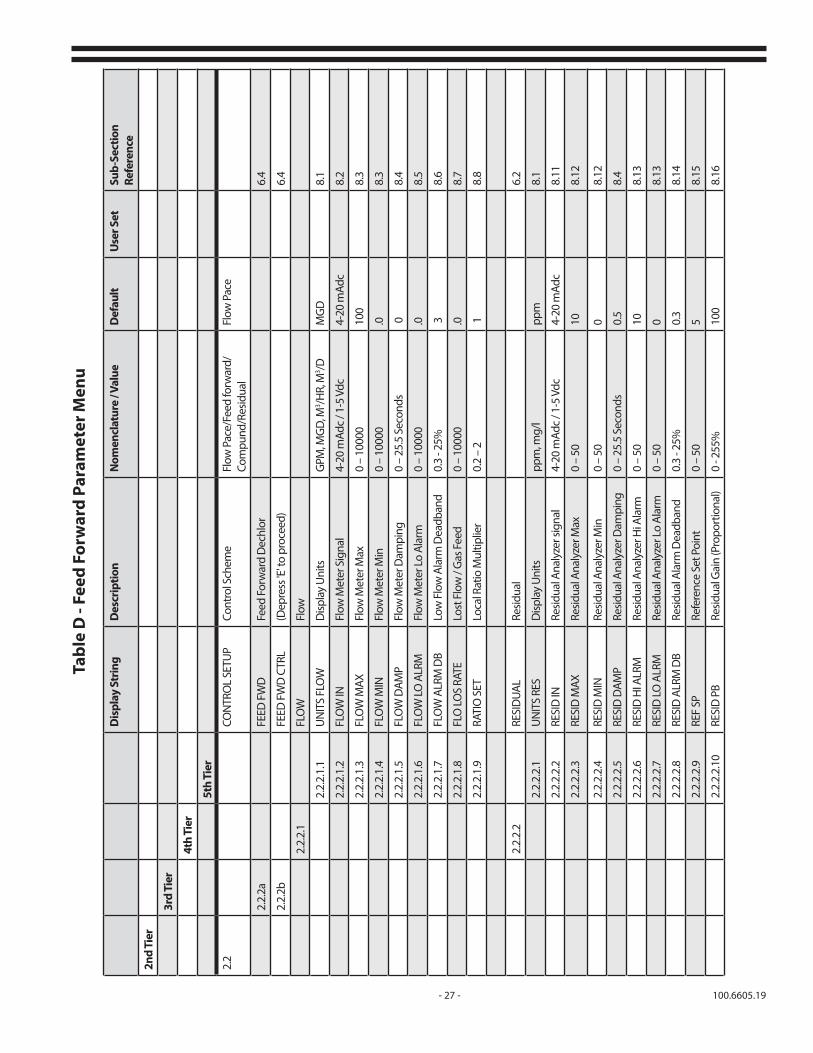
7.7.2 (2.2.2) FEED FORWARD CONTROLTable D indicates the parameters for the Feed Forward Control mode of operation. Using the U and D keys scroll through the parameter list. If the default nomenclature or value is acceptable, scroll to the next parameter. Depress the E key when a parameter appears in the display that you wish to change.
When entering a value, using the U and D keys will increase or decrease the value shown. The key can be continuously depressed and released or held to reach the desired value. With the key held depressed the first increase/decrease level will be units then speed up in increments of tens and then to hundreds increments to rapidly reach the desired setting.
When entering a nomenclature data point, using the U and D keys will scroll through the applicable list for that parameter.
After setting the value or nomenclature, depress the E key. Continue to use the U or D key to scroll to the next data point and change the nomenclature or value as described above.
After the values have been entered, the valve may be placed into operation by continuously depressing the M key until the top tier menu is displayed. Using the U or D keys scroll to RUN MODE and depress the E key. Using the U or D keys scroll through the menu to observe the valve operating conditions. Table E shows the applicable parameters for the Feed Forward mode in either automatic or manual operation. The parameters shown are observable even if password protection has been established. Only those parameters applicable to the chosen mode of operation will be shown.
2nd Tier Display String FunctionParameters Displayed in Auto Mode
Parameters Displayed in Manual Mode
3rd Tier Indicate Select
1.1 Run Mode - Flow Pace Run Mode - Flow Pace
1.1.1 L/R STAT X Local / Remote
1.1.2 GAS STAT X Gas Type Gas Type
1.1.3 GAS FLOW STAT X Gas Flow Gas Flow
1.1.4 FLOW STAT X Process Flow Process Flow
1.1.5 REM RATIO X X Remote Ratio Input
1.1.6 RATIO SET X X Flow Pace Ratio
1.1.7 REM RATIO IN X X Remote Ratio Input Signal
1.1.8 A/M CONFIG X X Auto / Manual Auto / Manual
Table C - Flow Pace Run Mode Menu
- 27 - 100.6605.19
Dis
play
Str
ing
Des
crip
tion
Nom
encl
atur
e / V
alue
Def
ault
Use
r Set
Sub-
Sect
ion
Refe
renc
e
2nd
Tier
3rd
Tier
4th
Tier
5th
Tier
2.2
CON
TRO
L SE
TUP
Cont
rol S
chem
eFl
ow P
ace/
Feed
forw
ard/
Com
pund
/Res
idua
lFl
ow P
ace
2.2.
2aFE
ED F
WD
Feed
For
war
d D
echl
or6.
4
2.2.
2bFE
ED F
WD
CTR
L(D
epre
ss 'E
' to
proc
eed)
6.4
2.2.
2.1
FLO
WFl
ow
2.2.
2.1.
1U
NIT
S FL
OW
Disp
lay
Uni
tsG
PM, M
GD
, M3 /H
R, M
3 /DM
GD
8.1
2.2.
2.1.
2FL
OW
INFl
ow M
eter
Sig
nal
4-20
mAd
c / 1
-5 V
dc4-
20 m
Adc
8.2
2.2.
2.1.
3FL
OW
MAX
Flow
Met
er M
ax0
– 10
000
100
8.3
2.2.
2.1.
4FL
OW
MIN
Flow
Met
er M
in0
– 10
000
.08.
3
2.2.
2.1.
5FL
OW
DAM
P Fl
ow M
eter
Dam
ping
0 –
25.5
Sec
onds
08.
4
2.2.
2.1.
6FL
OW
LO A
LRM
Flow
Met
er L
o Al
arm
0 –
1000
0.0
8.5
2.2.
2.1.
7FL
OW
ALR
M D
BLo
w F
low
Ala
rm D
eadb
and
0.3
- 25%
38.
6
2.2.
2.1.
8FL
O LO
S RA
TELo
st F
low
/ G
as F
eed
0 –
1000
0.0
8.7
2.2.
2.1.
9RA
TIO
SET
Loca
l Rat
io M
ultip
lier
0.2
– 2
18.
8
2.2.
2.2
RESI
DUA
LRe
sidua
l6.
2
2.2.
2.2.
1U
NIT
S RE
SD
ispla
y U
nits
ppm
, mg/
lpp
m8.
1
2.2.
2.2.
2RE
SID
INRe
sidua
l Ana
lyze
r sig
nal
4-20
mAd
c / 1
-5 V
dc4-
20 m
Adc
8.11
2.2.
2.2.
3RE
SID
MAX
Resid
ual A
naly
zer M
ax0
– 50
108.
12
2.2.
2.2.
4RE
SID
MIN
Resid
ual A
naly
zer M
in0
– 50
08.
12
2.2.
2.2.
5RE
SID
DAM
PRe
sidua
l Ana
lyze
r Dam
ping
0 –
25.5
Sec
onds
0.5
8.4
2.2.
2.2.
6RE
SID
HI A
LRM
Resid
ual A
naly
zer H
i Ala
rm0
– 50
108.
13
2.2.
2.2.
7RE
SID
LO A
LRM
Resid
ual A
naly
zer L
o Al
arm
0 –
500
8.13
2.2.
2.2.
8RE
SID
ALR
M D
BRe
sidua
l Ala
rm D
eadb
and
0.3
- 25%
0.3
8.14
2.2.
2.2.
9RE
F SP
Refe
renc
e Se
t Poi
nt0
– 50
58.
15
2.2.
2.2.
10RE
SID
PB
Resid
ual G
ain
(Pro
port
iona
l)0
- 255
%10
08.
16
Tabl
e D
- Fe
ed F
orw
ard
Para
met
er M
enu

100.6605.19 - 28 -
7.7.3 (2.2.3) COMPOUND LOOP CONTROLTable F indicates the parameters for the Compound Loop Control mode of operation. Using the U and D keys scroll through the parameter list. If the default nomenclature or value is acceptable, scroll to the next parameter. Depress the E key when a parameter appears in the display that you wish to change.
When entering a value, using the U and D keys will increase or decrease the value shown.
2nd Tier Display String Function Parameters Displayed
in Auto ModeParameters Displayed in Manual Mode
3rd Tier Indicate Select
1.2 Run Mode - Feed Forward
Run Mode - Feed Forward
1.2.1 L/R STAT X (Always local)1.2.2 RESID STAT X Residual Indication Residual Indication1.2.3 GAS STAT X Gas Type Gas Type
1.2.4 GAS FLOW STAT X Gas Flow Gas Flow
1.2.5 FLOW STAT X Process Flow Process Flow1.2.6 RATIO SET X X Flow Pace Ratio1.2.7 REF SP X X Reference Set Point1.2.8 A/M CONFIG X X Auto / Manual Auto / Manual
Table E - Feed Forward Control Run Mode Menu
The key can be continuously depressed and released or held to reach the desired value. With the key held depressed the first increase/decrease level will be units then speed up in increments of tens and then to hundreds increments to rapidly reach the desired setting.
When entering a nomenclature data point, using the U and D keys will scroll through the applicable list for that parameter.
After setting the value or nomenclature, depress the E key. Continue to use the U or D key to scroll to the next data point and change the nomenclature or value as described above.After the values have been entered, the valve may be placed into operation by continuously depressing the M key until the top tier menu is displayed. Using the U or D keys scroll to RUN MODE and depress the E key. Using the U or D keys scroll through the menu to observe the valve operating conditions. Table G shows the applicable parameters for the Compound Loop Control mode in either automatic or manual operation. The parameters shown are observable even if password protection has been established. Only those parameters applicable to the chosen mode of operation will be shown.

- 29 - 100.6605.19
Dis
play
Str
ing
Des
crip
tion
Nom
encl
atur
e / V
alue
Def
ault
Use
r Set
Sub-
Sect
ion
Refe
renc
e
2nd
Tier
3rd
Tier
4th
Tier
5th
Tier
6th
Tier
2.2
CON
TRO
L SE
TUP
Cont
rol S
chem
eFl
ow P
ace
/ Fee
d Fo
rwar
d /
Com
poun
d / R
esid
ual
Flow
Pac
e
2.2.
3aCO
MPO
UN
DCo
mpo
und
Loop
6.3
2.2.
3bCO
MPO
UN
D C
TRL
(Dep
ress
'E' t
o pr
ocee
d)
2.2.
3.1
FLO
WFl
ow
2.2.
3.1.
1U
NIT
S FL
OW
Disp
lay
Uni
tsG
PM, M
GD
, M3 /H
R, M
3 /DM
GD
8.1
2.2.
3.1.
2FL
OW
INFl
ow M
eter
Sig
nal
4-20
mAd
c / 1
-5 V
dc4-
20 m
Adc
8.2
2.2.
3.1.
3FL
OW
MAX
Flow
Met
er M
ax0
– 10
000
100
8.3
2.2.
3.1.
4FL
OW
MIN
Flow
Met
er M
in0
– 10
000
.08.
3
2.2.
3.1.
5FL
OW
DAM
P Fl
ow M
eter
Dam
ping
0 –
25.5
Sec
onds
08.
4
2.2.
3.1.
6FL
OW
LO A
LRM
Flow
Met
er L
o Al
arm
0 –
1000
0.0
8.5
2.2.
3.1.
7FL
OW
ALR
M D
BLo
w F
low
Ala
rm D
ead-
band
0.3
- 25%
38.
6
2.2.
3.1.
8RA
TIO
SET
Loca
l Rat
io M
ultip
lier
0.2
– 2
18.
8
2.2.
3.2
RESI
DUA
LRe
sidua
l6.
2
2.2.
3.2.
1U
NIT
S RE
SD
ispla
y U
nits
ppm
, mg/
lpp
m8.
1
2.2.
3.2.
2RE
SID
INRe
sidua
l ana
lyze
r sig
nal
4-20
mAd
c / 1
-5 V
dc4-
20 m
Adc
8.11
2.2.
3.2.
3RE
SID
MAX
Resid
ual A
naly
zer M
ax0
– 50
108.
12
2.2.
3.2.
4RE
SID
MIN
Resid
ual A
naly
zer M
in0
– 50
08.
12
2.2.
3.2.
5RE
SID
DAM
PRe
sidua
l Ana
lyze
r Dam
p-in
g0
– 25
.5 S
econ
ds0.
58.
4
2.2.
3.2.
6RE
SID
HI A
LRM
Resid
ual A
naly
zer H
i Al
arm
0 –
5010
8.13
2.2.
3.2.
7RE
SID
LO A
LRM
Resid
ual A
naly
zer L
o Al
arm
0 –
500
8.13
2.2.
3.2.
8RE
SID
ALR
M D
BRe
sidua
l Ala
rm D
eadb
and
0.3
- 25%
0.3
8.14
Tabl
e F
- Com
poun
d Lo
op P
aram
eter
Men
u

100.6605.19 - 30 -
Dis
play
Str
ing
Des
crip
tion
Nom
encl
atur
e / V
alue
Def
ault
Use
r Set
Sub-
Sect
ion
Refe
renc
e
2nd
Tier
3rd
Tier
4th
Tier
5th
Tier
6th
Tier
2.2.
3.2.
9PR
OPO
R BA
ND
Prop
ortio
nal B
and
(Gai
n)0
- 255
%10
08.
17
2.2.
3.2.
10IN
TEG
RAL
Inte
gral
tim
e0
- 60
min
s3
8.17
2.2.
3.2.
11A
DA
PT R
ESET
Adap
tive
Rese
t (In
-te
gral
)Ye
s / N
oN
o8.
18
2.2.
3.2.
11.1
FLO
W T
IME
HI
Max
Flo
w In
tegr
al0
- 60
min
s20
8.18
2.2.
3.2.
11.2
FLO
W L
OLo
w F
low
0 –
1000
02
8.18
2.2.
3.2.
11.3
FLO
W T
IME
LOLo
w F
low
Inte
gral
0 - 6
0 m
ins
458.
18
2.2.
3.2.
12RE
MO
TE S
PRe
mot
e Se
t Poi
ntYe
s / N
oN
o8.
19
2.2.
3.2.
13SP
Set P
oint
0 –
505
8.20
2.2.
3.2.
13.1
REM
SP
INRe
mot
e Se
t Poi
nt
Sign
al4-
20 m
Adc
/ 1-5
Vdc
4-20
mAd
c8.
21
2.2.
3.2.
14SP
DEV
ALR
MSe
tpoi
nt D
evia
tion
Ala
rm0.
3 - 2
5%25
8.22
Tabl
e F
- Com
poun
d Lo
op C
ontr
ol P
aram
eter
Men
u (c
onti
nued
)
- 31 - 100.6605.19
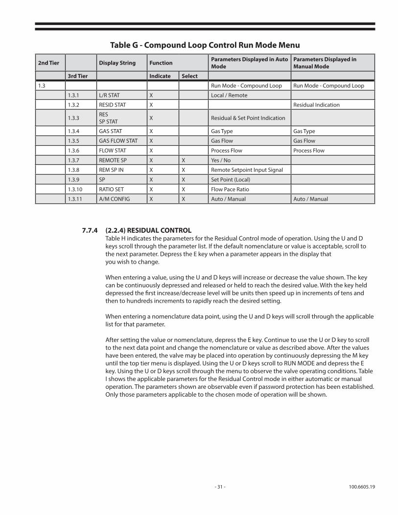
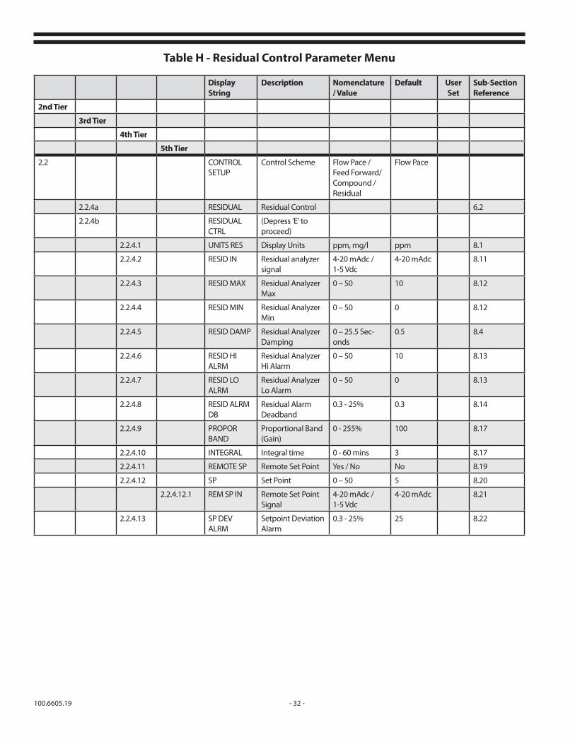
7.7.4 (2.2.4) RESIDUAL CONTROLTable H indicates the parameters for the Residual Control mode of operation. Using the U and D keys scroll through the parameter list. If the default nomenclature or value is acceptable, scroll to the next parameter. Depress the E key when a parameter appears in the display that you wish to change.
When entering a value, using the U and D keys will increase or decrease the value shown. The key can be continuously depressed and released or held to reach the desired value. With the key held depressed the first increase/decrease level will be units then speed up in increments of tens and then to hundreds increments to rapidly reach the desired setting.
When entering a nomenclature data point, using the U and D keys will scroll through the applicable list for that parameter.
After setting the value or nomenclature, depress the E key. Continue to use the U or D key to scroll to the next data point and change the nomenclature or value as described above. After the values have been entered, the valve may be placed into operation by continuously depressing the M key until the top tier menu is displayed. Using the U or D keys scroll to RUN MODE and depress the E key. Using the U or D keys scroll through the menu to observe the valve operating conditions. Table I shows the applicable parameters for the Residual Control mode in either automatic or manual operation. The parameters shown are observable even if password protection has been established. Only those parameters applicable to the chosen mode of operation will be shown.
2nd Tier Display String Function Parameters Displayed in Auto Mode
Parameters Displayed in Manual Mode
3rd Tier Indicate Select
1.3 Run Mode - Compound Loop Run Mode - Compound Loop
1.3.1 L/R STAT X Local / Remote
1.3.2 RESID STAT X Residual Indication
1.3.3RES SP STAT
X Residual & Set Point Indication
1.3.4 GAS STAT X Gas Type Gas Type
1.3.5 GAS FLOW STAT X Gas Flow Gas Flow
1.3.6 FLOW STAT X Process Flow Process Flow
1.3.7 REMOTE SP X X Yes / No
1.3.8 REM SP IN X X Remote Setpoint Input Signal
1.3.9 SP X X Set Point (Local)
1.3.10 RATIO SET X X Flow Pace Ratio
1.3.11 A/M CONFIG X X Auto / Manual Auto / Manual
Table G - Compound Loop Control Run Mode Menu
100.6605.19 - 32 -
Display String
Description Nomenclature / Value
Default User Set
Sub-Section Reference
2nd Tier
3rd Tier
4th Tier
5th Tier
2.2 CONTROL SETUP
Control Scheme Flow Pace / Feed Forward/ Compound / Residual
Flow Pace
2.2.4a RESIDUAL Residual Control 6.2
2.2.4b RESIDUALCTRL
(Depress 'E' to proceed)
2.2.4.1 UNITS RES Display Units ppm, mg/l ppm 8.1
2.2.4.2 RESID IN Residual analyzer signal
4-20 mAdc / 1-5 Vdc
4-20 mAdc 8.11
2.2.4.3 RESID MAX Residual Analyzer Max
0 – 50 10 8.12
2.2.4.4 RESID MIN Residual Analyzer Min
0 – 50 0 8.12
2.2.4.5 RESID DAMP Residual Analyzer Damping
0 – 25.5 Sec-onds
0.5 8.4
2.2.4.6 RESID HI ALRM
Residual Analyzer Hi Alarm
0 – 50 10 8.13
2.2.4.7 RESID LO ALRM
Residual Analyzer Lo Alarm
0 – 50 0 8.13
2.2.4.8 RESID ALRM DB
Residual Alarm Deadband
0.3 - 25% 0.3 8.14
2.2.4.9 PROPOR BAND
Proportional Band (Gain)
0 - 255% 100 8.17
2.2.4.10 INTEGRAL Integral time 0 - 60 mins 3 8.17
2.2.4.11 REMOTE SP Remote Set Point Yes / No No 8.19
2.2.4.12 SP Set Point 0 – 50 5 8.20
2.2.4.12.1 REM SP IN Remote Set Point Signal
4-20 mAdc / 1-5 Vdc
4-20 mAdc 8.21
2.2.4.13 SP DEV ALRM
Setpoint Deviation Alarm
0.3 - 25% 25 8.22
Table H - Residual Control Parameter Menu
- 33 - 100.6605.19
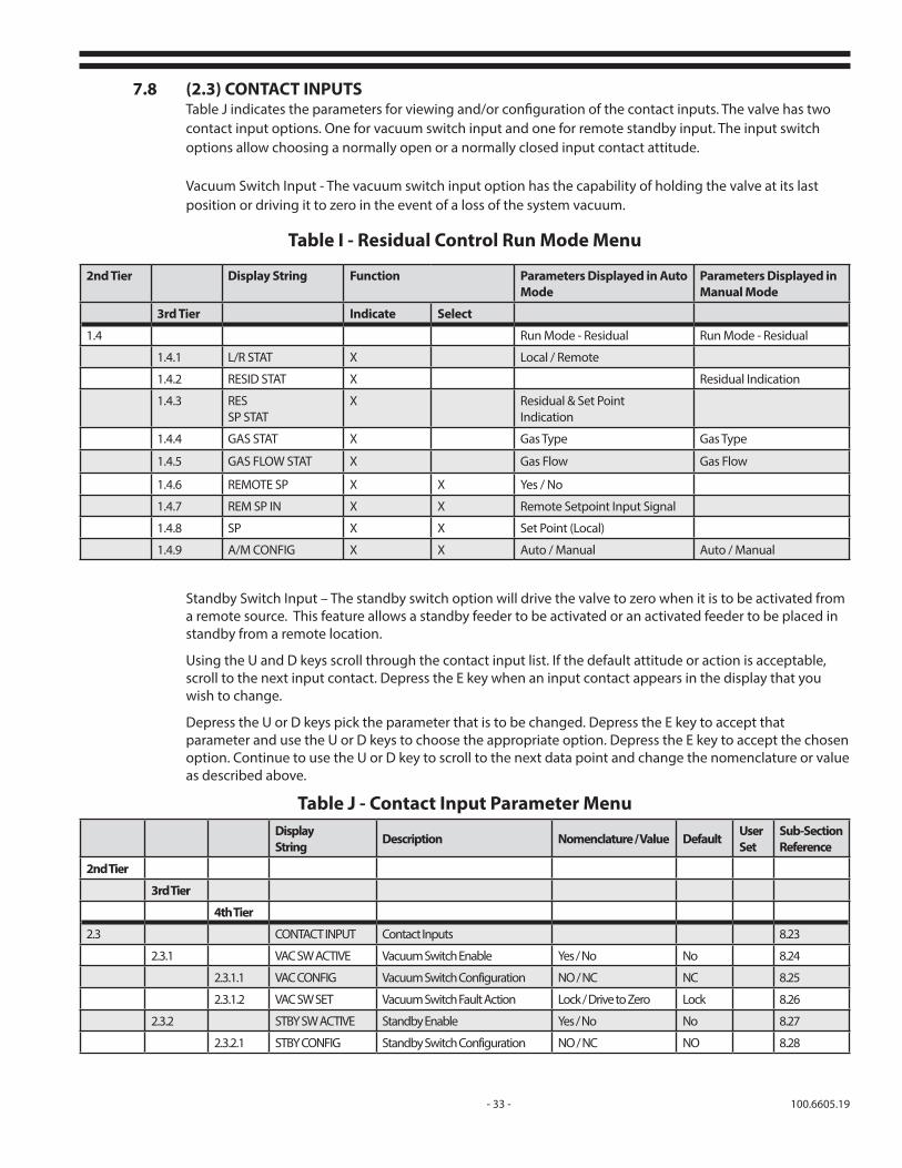
7.8 (2.3) CONTACT INPUTSTable J indicates the parameters for viewing and/or configuration of the contact inputs. The valve has two contact input options. One for vacuum switch input and one for remote standby input. The input switch options allow choosing a normally open or a normally closed input contact attitude.
Vacuum Switch Input - The vacuum switch input option has the capability of holding the valve at its last position or driving it to zero in the event of a loss of the system vacuum.
2nd Tier Display String Function Parameters Displayed in Auto Mode
Parameters Displayed in Manual Mode
3rd Tier Indicate Select
1.4 Run Mode - Residual Run Mode - Residual
1.4.1 L/R STAT X Local / Remote
1.4.2 RESID STAT X Residual Indication
1.4.3 RES SP STAT
X Residual & Set PointIndication
1.4.4 GAS STAT X Gas Type Gas Type
1.4.5 GAS FLOW STAT X Gas Flow Gas Flow
1.4.6 REMOTE SP X X Yes / No
1.4.7 REM SP IN X X Remote Setpoint Input Signal
1.4.8 SP X X Set Point (Local)
1.4.9 A/M CONFIG X X Auto / Manual Auto / Manual
Table I - Residual Control Run Mode Menu
Standby Switch Input – The standby switch option will drive the valve to zero when it is to be activated from a remote source. This feature allows a standby feeder to be activated or an activated feeder to be placed in standby from a remote location.
Using the U and D keys scroll through the contact input list. If the default attitude or action is acceptable, scroll to the next input contact. Depress the E key when an input contact appears in the display that you wish to change.
Depress the U or D keys pick the parameter that is to be changed. Depress the E key to accept that parameter and use the U or D keys to choose the appropriate option. Depress the E key to accept the chosen option. Continue to use the U or D key to scroll to the next data point and change the nomenclature or value as described above.
Display String Description Nomenclature / Value Default User
SetSub-Section Reference
2nd Tier
3rd Tier
4th Tier
2.3 CONTACT INPUT Contact Inputs 8.23
2.3.1 VAC SW ACTIVE Vacuum Switch Enable Yes / No No 8.24
2.3.1.1 VAC CONFIG Vacuum Switch Configuration NO / NC NC 8.25
2.3.1.2 VAC SW SET Vacuum Switch Fault Action Lock / Drive to Zero Lock 8.26
2.3.2 STBY SW ACTIVE Standby Enable Yes / No No 8.27
2.3.2.1 STBY CONFIG Standby Switch Configuration NO / NC NO 8.28
Table J - Contact Input Parameter Menu
100.6605.19 - 34 -
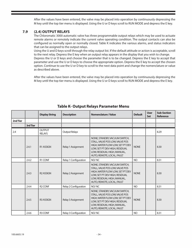
After the values have been entered, the valve may be placed into operation by continuously depressing the M key until the top tier menu is displayed. Using the U or D keys scroll to RUN MODE and depress the E key.
7.9 (2.4) OUTPUT RELAYSThe Chloromatic 3000 automatic valve has three programmable output relays which may be used to actuate remote alarms or remotely indicate the current valve operating condition. The output contacts can also be configured as normally open or normally closed. Table K indicates the various alarms, and status indicators that can be assigned to the output relays.Using the U and D keys scroll through the relay output list. If the default attitude or action is acceptable, scroll to the next relay. Depress the E key when an output relay appears in the display that you wish to change. Depress the U or D keys and choose the parameter that is to be changed. Depress the E key to accept that parameter and use the U or D keys to choose the appropriate option. Depress the E key to accept the chosen option. Continue to use the U or D key to scroll to the next data point and change the nomenclature or value as described above.
After the values have been entered, the valve may be placed into operation by continuously depressing the M key until the top tier menu is displayed. Using the U or D keys scroll to RUN MODE and depress the E key.
Display String Description Nomenclature / Value Default User Set
Sub-Section Reference
2nd Tier
3rd Tier
2.4OUTPUT RELAYS
Output Relays 8.29
2.4.1 R1 ASSIGN Relay 1 Assignment
NONE, STANDBY, VACUUM SWITCH, STALL, VALVE POS LOW, VALVE POS HIGH, WATER FLOW LOW, SET PT DEV LOW, SET PT DEV HIGH, RESIDUAL LOW, RESIDUAL HIGH, MANUAL, AUTO, REMOTE, LOCAL, FAULT
NONE 8.30
2.4.2 R1 CONF Relay 1 Configuration NO/ NC NO 8.31
2.4.3 R2 ASSIGN Relay 2 Assignment
NONE, STANDBY, VACUUM SWITCH, STALL, VALVE POS LOW, VALVE POS HIGH, WATER FLOW LOW, SET PT DEV LOW, SET PT DEV HIGH, RESIDUAL LOW, RESIDUAL HIGH, MANUAL, AUTO, REMOTE, LOCAL, FAULT
NONE 8.30
2.4.4 R2 CONF Relay 2 Configuration NO/ NC NO 8.31
2.4.5 R3 ASSIGN Relay 3 Assignment
NONE, STANDBY, VACUUM SWITCH, STALL, VALVE POS LOW, VALVE POS HIGH, WATER FLOW LOW, SET PT DEV LOW, SET PT DEV HIGH, RESIDUAL LOW, RESIDUAL HIGH, MANUAL, AUTO, REMOTE, LOCAL, FAULT
NONE 8.30
2.4.6 R3 CONF Relay 3 Configuration NO/ NC NO 8.31
Table K- Output Relays Parameter Menu

- 35 - 100.6605.19
7.10 (2.5) DEFAULTSThe DEFAULTS section of the menu tree shown in Table L below indicates the various default values or settings as set at the factory or chosen by the user. To access the DEFAULTS menu, depress the M key several times to return to the top tier menu. Depress the U or D keys until SETUP appears. Depress the E key. Depress the U or D keys until DEFAULTS appears. Using the U or D keys scroll through the menu until the desired DEFAULT display appears. Depress the E key and using the U or D keys change the action or value as required.
The following is a description of each of the DEFAULT items:LOAD CUS DEF – The operational parameters that were entered in the SETUP steps above may be saved as the custom setting for your facility. The parameter configuration that was saved in the SET CUS DEFS step below can be recalled in order to bring up the valve settings, for the last saved setup, back to that configuration.
SET CUS DEFS - The parameters that have been entered in the SETUP steps, as described in the previous paragraphs above, may be permanently saved. In this manner, should subsequent changes be made that are not proving to be acceptable, the prior settings can be reloaded to return the valve to its previous mode of operation.
Display String Description Nomenclature / Value Default User Set
Sub-Section Reference
2nd Tier
3rd Tier
2.5 DEFAULTS Defaults 7.10
2.5.1 LOAD CUS DEF Load Customer Defaults Yes / No No 7.10
2.5.2 SET CUS DEFS Save Current Settings Yes / No No 7.10
2.5.3 LOAD FAC DEFS Load Factory Defaults Yes / No No 7.10
2.5.4 PASS PROTECT Password Protection Yes / No No 7.10
2.5.5 SET PASS Set New Password Yes / No No 7.10
2.5.6 PASSWORD Enter Password Enter 4 letters any combination
---- 7.10
2.5.7 INVERT DISPLAY Invert Display ------ No 7.3
2.5.8 HYSTER CNT Hystersys Count Factory set - do not change 2 ------ 7.10
2.5.9 DEADBAND CT Deadband Count Factory set - do not change 6 ------ 7.10
Table L - Defaults Parameter Menu
LOAD FAC DEFS – Allows the operator to return the setup parameters to those set at the factory.
PASS PROTECT, SET PASS, PASSWORD – Password protection will prevent the changing of set-up parameters and the operating parameters shown in the 'select' columns of the various run mode tables (Table C, E, G and I).
The three menu display strings work together to establish password protection. Declaring "yes" at the PASS PROTECT window and not establishing a password in the PASSWORD window will not establish password protection unless a password has been previously established.
After a password has been established it may be turned on and off in the PASS PROTECT window. Also, after establishing password protection (2.5.4) there is a 30 second delay before it takes effect if no buttons have been pushed during the time-out period.
INVERT DISPLAY – As described in Section 7.3 above The display can be inverted to accommodate a valve mounting attitude with the valve body above or below the operator. Depress the E key and using U or D Keys, scroll to YES. Depress the E key.
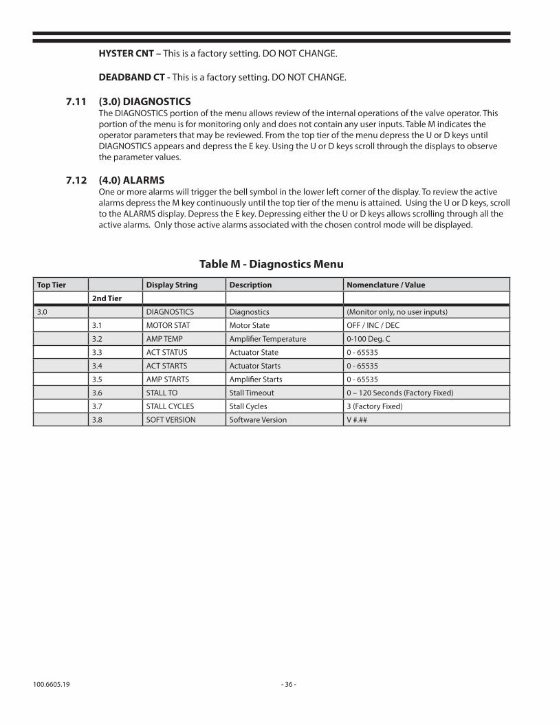
100.6605.19 - 36 -
HYSTER CNT – This is a factory setting. DO NOT CHANGE.
DEADBAND CT - This is a factory setting. DO NOT CHANGE.
7.11 (3.0) DIAGNOSTICSThe DIAGNOSTICS portion of the menu allows review of the internal operations of the valve operator. This portion of the menu is for monitoring only and does not contain any user inputs. Table M indicates the operator parameters that may be reviewed. From the top tier of the menu depress the U or D keys until DIAGNOSTICS appears and depress the E key. Using the U or D keys scroll through the displays to observe the parameter values.
7.12 (4.0) ALARMSOne or more alarms will trigger the bell symbol in the lower left corner of the display. To review the active alarms depress the M key continuously until the top tier of the menu is attained. Using the U or D keys, scroll to the ALARMS display. Depress the E key. Depressing either the U or D keys allows scrolling through all the active alarms. Only those active alarms associated with the chosen control mode will be displayed.
Top Tier Display String Description Nomenclature / Value
2nd Tier
3.0 DIAGNOSTICS Diagnostics (Monitor only, no user inputs)
3.1 MOTOR STAT Motor State OFF / INC / DEC
3.2 AMP TEMP Amplifier Temperature 0-100 Deg. C
3.3 ACT STATUS Actuator State 0 - 65535
3.4 ACT STARTS Actuator Starts 0 - 65535
3.5 AMP STARTS Amplifier Starts 0 - 65535
3.6 STALL TO Stall Timeout 0 – 120 Seconds (Factory Fixed)
3.7 STALL CYCLES Stall Cycles 3 (Factory Fixed)
3.8 SOFT VERSION Software Version V #.##
Table M - Diagnostics Menu

- 37 - 100.6605.19
8 PARAMETER DESCRIPTIONSThe control strategies as described in Section 6.0 and set in Section 7.0 provide information about parameters that are unique to the strategy. This section is devoted to providing information about parameters that are common to more than one strategy. It provides: • insight into the significance of the parameters • guidance in determining the parameter values most appropriate for your applicationOnce you have determined the appropriate parameter values for your site, follow the instructions in Section 7 to display and change parameter values.
8.1 Display Units
The UNITS FLOW and UNITS RES settings allow selection of the units to be displayed for all parameters that are associated with the input process water flow and residual measurements. The flow parameter options are GPM, MGD, m3/hr or m3/day. The residual parameter options are ppm or mg/l.
8.2 Flow Meter SignalThe FLOW IN parameter configures the type of flow meter signal that the 3000 valve will accept. Either a 4-20 mAdc or a 1-5 Vdc signal may be selected. Referring to Figure 4 position switch S1 in the appropriate position.
8.3 Process Water Flow and Gas Dispenser OutputFor accurate operation of the flow control loop, it is important that the process water flow and gas ranges be entered properly. The water flow range must be set at maximum (100% of the flowmeter output). The gas range must be set at the maximum output of the gas dispenser. The control loop will not function properly unless the ranges are entered correctly.
Minimum water flow and minimum gas flow should normally be set to zero.
8.4 DampingDamping is the amount of time over which the flow meter or residual analyzer input signals are averaged. The setting may range from 0 seconds (no damping) to 25 seconds. This is used to smooth out rapid fluctuations of the input signal.
8.5 Flow Meter Low AlarmThe FLO LO ALRM can be set to a process flow rate indication that would not be possible unless the flow transmitter failed. 5% of maximum flow is a suggested setting. This alarm setting will trigger shifting the compound loop control mode into residual only control or drive the valve to a preset minimum gas flow rate depending on the control mode selected.
8.6 Low Flow Alarm DeadbandThe FLOW ALRM DB setting establishes when the water Low Flow Alarm is cleared. The input flow reading must rise above this level in order for the system to clear an existing Low Flow Alarm. The parameter may be set from 0.3% to 25% of the process flow range.
8.7 Lost flow / Gas FeedThe FLO LOS RATE setting allows the control valve to feed a preset minimum amount should the flow meter signal fail when in the flow pacing strategy mode.
8.8 Local Ratio MultiplierThe ratio multiplier, RATIO SET, allows the gas feed to track the process flow so that the dosage remains constant for changes in process flow. The multiplier range is from 0.2 to 2. A factor of 1 will yield maximum gas flow at maximum process flow.

100.6605.19 - 38 -
For example, a treatment facility with a maximum process flow of 8 MGD (1262 m3/h) has determined that a dosage of 5 PPM will yield the effluent residual required. Sizing the chlorinator yields:
US Units Metric UnitsPPD (required) = (MGD) X (8.34) X (Dosage) g/h = (m3/h) x (Dosage) = 8 X 8.34 X 5 = 1262 m3/h x 5 = 333.6 PPD = 6310 g/h or 6.3 kg/h
The closest chlorinator that can feed at the required rate has a maximum capacity of 500 PPD (10 kg/h). To compensate for the larger than required gas feeder, a ratio multiplier must be entered into the valve parameters. The multiplier is calculated as follows:
US Units Metric UnitsRATIO SET = Maximum or calculated feed = 6310 g/h Maximum capacity of the gas feeder 10,000 g/h = 333.6 500 = 0.667 (round to 0.7) = 0.631 (round to 0.7)
8.9 Remote Ratio SetREM RATIO determines whether the ratio multiplier in the flow pace control mode is obtained locally or remotely. When set to YES, the ratio multiplier is remote and the REM RATIO IN parameter is available. When set to NO, the ratio multiplier is local and the RATIO SET parameter is available for update at the valve.
8.10 Remote Ratio Set SignalThe REM RATIO IN parameter configures the type of remote signal that the 3000 valve will accept. Either a 4-20 mAdc or a 1-5 Vdc signal may be selected. Referring to Figure 4 position switch S3 in the appropriate position.
8.11 Residual Analyzer SignalThe RESID IN parameter configures the type of analyzer signal that the 3000 valve will accept. Either a 4-20 mAdc or a 1-5 Vdc signal may be selected. Referring to Figure 4 position switch S2 in the appropriate position.
8.12 Residual Analyzer Max and MinRESID MAX and RESID MIN parameters are the maximum and minimum range limits of the residual analyzer.
8.13 Residual Analyzer High and Low AlarmAn alarm indication is generated when the process residual signal exceeds the maximum setting or falls below the minimum setting.
8.14 Residual Alarm DeadbandThe RESID ALRM DB setting establishes when the RESID HI ALRM and RESID LO ALRM are cleared. The input analyzer reading must rise above the low setting or fall below the high setting in order for the system to clear an existing alarm. The parameter may be set from 0.3% to 25% of the process residual range.
8.15 Reference Set PointIn the feed forward mode of control the REF SP parameter sets the desired residual level. This parameter, along with the RESID PB setting determines the difference between the process residual and the setpoint and changes the valve position accordingly to bring the process to the setpoint. This calculated output is also combined with the process flow reading in order to maintain tighter control of the dechlorination gas.
8.16 Residual Proportional Band (gain)This is the gain that is applied to the difference between the REF SP and the process residual for the feed forward control mode. It tells the actuator what percentage of the difference to use as a step up or step down to the valve position. The correction amount is equal to 100 divided by the, RESID PB, proportional band setting.
- 39 - 100.6605.19
8.17 Controller TuningProportional Band and Integral (Reset) Time.The PI controller is designed to allow you to gradually increase or decrease the amount of gas going into the treatment process in response to a deviation between the residual and the setpoint. (Rapid, near instantaneous, increases or decreases in 3000 valve setting would cause over- or undershoots in residual.)
Achieving a gradual change is accomplished by a series of incremental steps. There is a lag timebetween the time the position of the 3000 valve is changed and the corresponding change in output of the analyzer is noted. In that case, for the controller to do its job properly, it must wait between incremental changes to allow the effects of the new gas dispenser setting to be evident at the analyzer. Depending on the plant lay-out and the process flow rate, it can take several minutes for a change to become evident. This lag time is entered as the INTEGRAL TIME.
Integral Time is determined by changing the 3000 valve position to increase the residual by 1 ppm and recording the time required for the analyzer to measure a corresponding change. This time interval is the Integral Time and corresponds to the specific process flow rate at that time. A better control strategy would include Adaptive Reset (see Section 8.18) if the control strategy with a constant Integral time setting causes fluctuations in residual due to fluctuating flow rates.
The size of the incremental changes the controller makes is determined by the proportional band setting. What you are really doing is telling the controller what percentage of the difference between the set point and the process variable you want to use as the step up or down. This is equal to 100 divided by the PERCENTAGE OF THE PROPORTIONAL BAND.
For example, if you use the proportional band setting 200%, you are telling the controller to make an incremental change equal to 100/200. Suppose you were using an Integral time of five minutes; then every five minutes the controller would tell the gas dispenser to add half the difference between the set point and the process variable. So if the controller determined that you needed to add 100 ppd, the first time it sent a signal to the gas dispenser, it would tell it to change the rate at which it is adding gas by 50 ppd. Then, five minutes later, it would tell the gas dispenser to increase its setting at the rate of 25 ppd. Five minutes after that it would tell it to change its setting at the rate of 12.5, and so forth.
These changes are made continuously, not in discrete steps as might be inferred from this simplified example.
8.18 Adaptive ResetAdaptive Reset applies only to Flow Paced Residual Trimmed and Feedback Dechlor strategies.It is available on menu reference 2.2.3.2 for Feedback Dechlor.
Adaptive Reset is an option which may be turned ON or OFF using the provided display.
This feature adds better control than achievable with standard Controller Tuning (Section 8.1) in that the Reset Time is made to respond to flow changes.
Chlorination systems can typically have long time intervals between chlorine injection and analyzer sampling. This time interval will often vary due to flow conditions. Adaptive Reset can be used to adjust the PI loop output to these changing parameters and still operate within user specified parameters. Entry of proper values permits rapid response to changing conditions without overshooting or undershooting the set point.
The following information is required for the proper application of Adaptive Reset. Steady High Flow Rate High Flow Rate Transit Time Steady Low Flow Rate Low Flow Rate Transit TimeAdaptive Reset Times should be measured at two, if possible significantly different, flow rates, say 40 and 100% of maximum flow. The measurements are carried out as follows:

100.6605.19 - 40 -
1. Measure a stable process flow and note the value.
2. Adjust the Chlorinator valve to increase the residual within the process stream by approximately 1 ppm.
3. Measure the time required for the Analyzer to show a corresponding increase in concen- tration. This time interval is the Integral Time at the measured flow rate.
4. Take measurements at both the high and low flow conditions and enter the values as noted in Section 7.7.3.
Integral Time may be determined using sulfur dioxide in an analogous manner.
The above two sets of parameters are used to compute a linear relationship between the flow and Integral Time.
When YES, the Adaptive Reset will calculate the appropriate amount of Integral Time and adjust the controller accordingly.
8.19 Remote Set PointCertain control strategies will require the control set point be input to the valve operator from a remote SCADA or control system. REMOTE SP allows the operator to choose between local or remote set point input.
8.20 Set PointSP is the local set point setting for the desired process residual.
8.21 Remote Set Point SignalThe REM SP IN parameter configures the type of remote setpoint signal that the Chloromatic 3000 valve will accept. Either a 4-20 mAdc or a 1-5 Vdc signal may be selected. Referring to the Figure 4 position switch S3 in the appropriate position.
8.22 Set Point Deviation AlarmThe parameter SP DEV ALRM establishes the percent of the residual signal by which the set point and residual signal may differ before an alarm is triggered. The difference will be for both positive as well as negative deviation. The settable range is 0.3 to 25%.
8.23 Contact InputsThe 3000 valve is equipped with two contact inputs that may be chosen and configured by the operator. (See paragraphs 8.24 and 8.27.)
8.24 Vacuum Switch EnableSetting the VAC SW ACTIVE parameter to YES enables the vacuum switch input. The vacuum switch is wired to switch input #1 to indicate a loss of motive vacuum for the gas feeder.
8.25 Vacuum Switch ConfigurationWhen the VAC SW ACTIVE parameter has been enabled, the VAC CONFIG is made accessible to the operator. When the vacuum switch contact is set to normally open (NO), action is taken when the contact closes. When the vacuum switch contact is set to normally closed (NC) action is taken when the contact opens.
8.26 Vacuum Switch Fault ActionTwo different default options can be chosen from the VAC SW SET display. The operator has a choice to LOCK the valve in its last position or DRIVE TO ZERO when the vacuum switch input is triggered. In addition the 4-20 mAdc gas flow retransmission signal is driven to 4 mAdc to remotely indicate a no-flow condition.
8.27 Standby EnableThe STBY SW ACTIVE display allows the valve to be activated (YES) or deactivated (NO) from a remote location by means of a switch contact.

- 41 - 100.6605.19
8.28 Standby ConfigurationThis display allows the input contact to be configured as a normally open (NO) or a normally closed (NC) contact. With a NO contact, action is taken when the contact closes and with a NC contact action is taken when the contact opens. When the standby switch is activated, the valve will be driven to the closed position and the alarm display will show STANDBY.
Note: When the valve is in the standby state other operational parameters may be changed by the operator. However, it is advisable to change the standby enable (STBY SW ACTIVE) to NO as the “STANDBY” indication will always show on the bottom line and block the view to the parameter changes.
8.29 Output RelaysThe 3000 valve has three output relays that are fully configurable by the user. They can be set to trigger on any one of fifteen fault/alarm or valve conditions. The output contacts are also configurable as normally open (NO) or normally closed (NC).
8.30 Relay 1, 2, 3 AssignmentThe following conditions may be applied to each of the output relays:
NONE – Relay unassigned.
STANDBY - Actuated as an indication that the valve has been placed in standby mode.
VACUUM SWITCH - Actuates when the appropriate vacuum switch contacts are connected to the vacuum switch input and either a high or low vacuum condition exists. The alarm condition is indicative of no gas flow.
STALL – Alarm condition indicating that the valve has been commanded to move and no movement has been detected within three seconds.
VALVE POS LOW – Alarm condition indicating that the valve has closed beyond a minimum setting.
VALVE POS HIGH – Alarm condition indicating that the valve has opened beyond a maximum setting.
WATER FLOW LOW – Low water flow alarm determined by the FLOW LO ALRM (Section 8.5).
SET PT DEV LOW – Alarm condition indicating that the residual is above the set point by a preset amount (Section 8.21).
SET PT DEV HIGH – Alarm condition indicating that the residual is below the set point by a preset amount (Section 8.21).
RESIDUAL LOW – Alarm condition indicating that the residual has dropped below a preset low limit (Section 8.13).
RESIDUAL HIGH – Alarm condition indicating that the residual has exceeded a preset high limit ( Section 8.13).
MANUAL – Contact action indicating that the valve is in manual operation.
AUTO - Contact action indicating that the valve is in automatic operation.
REMOTE - Contact action indicating that the valve is receiving a remote setpoint.
LOCAL - Contact action indicating that the valve is in local control.
FAULT - Contact action indicating problem as indicated in Section 8.32.
8.31 Relay 1, 2, 3 ConfigurationWhen either of the R1 or R2 or R3 ASSIGN parameters have been enabled, the R1 or R2 or R3 CONFIG is made accessible to the operator. Setting the output relay contact to normally open (NO), action is taken when the contact closes. Setting the output relay contact to normally closed (NC), action is taken when the contact opens.

100.6605.19 - 42 -
8.32 Alarm ListThe following are the possible alarm conditions that may be displayed during operation:
NONE – This word will appear when no alarms have been activated.
STANDBY - Actuated as an indication that the valve has been placed in standby mode.
VACUUM SWITCH - Actuates when the appropriate vacuum switch contacts are connected to the vacuum switch input and either a high or low vacuum condition exists. The alarm condition is indicative of no gas flow.
STALL - Alarm condition indicating that the valve has been commanded to move and no movement has been detected within three seconds.
WATER FLOW LOW – determined by the setting in FLOW LO ALRM (paragraph 8.5).
LOS FLOW – Actuated when the flow input signal drops below 3.6 mAdc or rises above 20.5 mAdc.
SET PT DEV HIGH – Actuated when the difference between the set point and the process variable exceed a preset amount as set in SP DEV ALRM (Section 8.22).
SET PT DEV LOW– Actuated when the difference between the set point and the process variable exceed a preset amount as set in SP DEV ALRM (Section 8.22).
RESIDUAL LOW – Actuated when the process variable drops below a preset point as set in RESID LO ALRM (Section 8.13)
RESIDUAL HIGH – Actuated when the process variable rises above a preset point as set in RESID HI ALRM (Section 8.13)
LOS RESID – Actuated when the residual input signal drops below 3.6 mAdc or rises above 20.5 mAdc.
VALVE POS LOW – Indicates that the valve is at its minimum position.
VALVE POS HIGH – Indicates that the valve is at its maximum position
LOS-RM SET PT – Actuated when the remote set point input signal drops below 3.6 mAdc or rises above 20.5 mAdc.
LOS-POSITION – Actuated when communication is lost with the feedback potentiometer.
FAULT – Actuated for loss of remote setpoint signal, loss of feedback pot communication, stalled actuator after two retries. The fault alarm can also be used for power failure remote indication by assigning it to a relay and configuring the relays as N.C. The contact will open upon power failure.
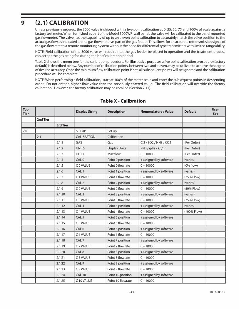
- 43 - 100.6605.19
9 (2.1) CALIBRATIONUnless previously ordered, the 3000 valve is shipped with a five point calibration at 0, 25, 50, 75 and 100% of scale against a factory test meter. When furnished as part of the Model 3000WP wall panel, the valve will be calibrated to the panel mounted gas flowmeter. The valve has the capability of up to an eleven point calibration to accurately match the valve position to the actual gas flow as indicated on the gas flow meter as part of the gas feeder. This allows for an accurate retransmission signal of the gas flow rate to a remote monitoring system without the need for differential type transmitters with limited rangeability.
NOTE: Field calibration of the 3000 valve will require that the gas feeder be placed in operation and the treatment process can accept the gas being fed during the brief calibration period.
Table X shows the menu tree for the calibration procedure. For illustrative purposes a five point calibration procedure (factory default) is described below. Any number of calibration points, between two and eleven, may be utilized to achieve the degree of desired accuracy. Once the minimum flow calibration point is set, all subsequent points will be ignored and the calibration procedure will be complete.
NOTE: When performing a field calibration, start at 100% of the meter scale and enter the subsequent points in descending order. Do not enter a higher flow value than the previously entered value. The field calibration will override the factory calibration. However, the factory calibration may be recalled (Section 7.11).
Table X - Calibration
Top Tier Display String Description Nomenclature / Value Default User
Set
2nd Tier
3rd Tier
2.0 SET UP Set up
2.1 CALIBRATION Calibration
2.1.1 GAS Gas Cl2 / SO2 / NH3 / CO2 (Per Order)
2.1.2 UNITS Display Units PPD / g/hr / kg/hr (Per Order)
2.1.3 HI FLO Max flow 0 – 10000 (Per Order)
2.1.4 CAL 0 Point 0 position # assigned by software (varies)
2.1.5 C 0 VALUE Point 0 flowrate 0 – 10000 (0% flow)
2.1.6 CAL 1 Point 1 position # assigned by software (varies)
2.1.7 C 1 VALUE Point 1 flowrate 0 – 10000 (25% Flow)
2.1.8 CAL 2 Point 2 position # assigned by software (varies)
2.1.9 C 2 VALUE Point 2 flowrate 0 – 10000 (50% Flow)
2.1.10 CAL 3 Point 3 position # assigned by software (varies)
2.1.11 C 3 VALUE Point 3 flowrate 0 – 10000 (75% Flow)
2.1.12 CAL 4 Point 4 position # assigned by software (varies)
2.1.13 C 4 VALUE Point 4 flowrate 0 – 10000 (100% Flow)
2.1.14 CAL 5 Point 5 position # assigned by software
2.1.15 C 5 VALUE Point 5 flowrate 0 – 10000
2.1.16 CAL 6 Point 6 position # assigned by software
2.1.17 C 6 VALUE Point 6 flowrate 0 – 10000
2.1.18 CAL 7 Point 7 position # assigned by software
2.1.19 C 7 VALUE Point 7 flowrate 0 – 10000
2.1.20 CAL 8 Point 8 position # assigned by software
2.1.21 C 8 VALUE Point 8 flowrate 0 – 10000
2.1.22 CAL 9 Point 9 position # assigned by software
2.1.23 C 9 VALUE Point 9 flowrate 0 – 10000
2.1.24 CAL 10 Point 10 position # assigned by software
2.1.25 C 10 VALUE Point 10 flowrate 0 – 10000

100.6605.19 - 44 -
For your reference, Table Y below shows the percent of full scale positions for the various calibration points based on the total number of calibration steps desired. A 5 point field calibration is shown as an example.
1. To enter CALIBRATION mode, continuously depress the M key until there is no display change2. Press either the U or D keys until SET UP appears3. Press the E key4. Press either the U or D keys until CALIBRATION is displayed5. Press the E key. The gas type will appear. If no change is desired, proceed to step 8. If a different choice is desired, press the E key again.
NOTE: Changing the gas type for the display may require a materials change for the valve plug and seals. Refer to parts list 100.7091.
6. Press the U or D Keys to change to the desired gas type.7. Press the E key to save the parameter.8. Press D to display UNITS. The units of gas flow measurement will appear. If no change is desired, proceed to step 11. If a different choice is desired, press the E key again.9. Press the U or D Keys to change to the desired UNITS of measurement.
Calibration Steps
Scale % 2 3 4 5 6 7 8 9 11
0 Cal 0 Cal 0 Cal 0 Cal 0 Cal 0 Cal 0 Cal 0 Cal 0 Cal 0
10 Cal 1
12.5 Cal 1
14.3 Cal 1
16.7 Cal 1
20 Cal 1 Cal 2
25 Cal 1 Cal 2
28.6 Cal 2
30 Cal 3
33.3 Cal 1 Cal 2
37.5 Cal 3
40 Cal 2 Cal 4
42.9 Cal 3
50 Cal 1 Cal 2 Cal 3 Cal 4 Cal 5
57.1 Cal 4
60 Cal 3 Cal 6
62.5 Cal 5
66.6 Cal 2 Cal 4
70 Cal 7
71.4 Cal 5
75 Cal 3 Cal 6
80 Cal 4 Cal 8
83.3 Cal 5
85.7 Cal 6
87.5 Cal 7
90 Cal 9
100 Cal 1 Cal 2 Cal 3 Cal 4 Cal 5 Cal 6 Cal 7 Cal 8 Cal 10
Table Y - Calibration Steps

- 45 - 100.6605.19
10. Press E to save the chosen UNITS.11. Press D to display HI FLOW. The units of gas flow measurement will appear. If no change is desired, proceed to step 14. If a different choice is desired, press the E key.12. Press the U or D Keys to change the maximum gas flow rate.13. Press E to save the parameter.14. Press the D Key to Display CAL 415. Press the E Key to Edit CAL 416. While observing the flow meter of the gas feeder, press the U or D Keys to adjust the gas feed rate to the maximum gas flow rate.17. Press the E Key to save the CAL 4 18. Press the D Key to display the C 4 VALUE. The units of gas flow measurement will appear. If no change is desired, proceed to step 21. If a different choice is desired, press the E key.19. Use the U or D Key to edit the C 4 VALUE.20. Press the E Key to Save the C 4 VALUE21. Press the U Key to Display CAL 322. Press the E Key to Edit CAL 323. Press the U or D Keys to adjust the Cal 3 for 75% of maximum gas flow.24. Press the E Key to save the CAL 3 25. Press the D Key to display the C 3 VALUE26. Press the E Key to Edit the C 3 VALUE27. Use the U or D Keys to indicate the 75% of maximum gas flow rate.28. Press the E Key to Save the C 3 VALUE29. Press the D Key to Display CAL 230. Press the E Key to Edit CAL 231. Press the U or D Key to adjust the Cal 2 for 50% of maximum gas flow.32. Press the E Key to save the CAL 2 33. Press the D Key to display the C 2 VALUE34. Press the E Key to Edit the C 2 VALUE35. Use the U or D Keys to indicate the 50% of maximum gas flow rate.36. Press the E Key to Save the C 2 VALUE37. Press the U Key to Display CAL 138. Press the E Key to Edit CAL 139. Press the U or D Keys to adjust the Cal 1 for 25% of maximum gas flow.40. Press the E Key to save the CAL 1 41. Press the D Key to display the C 1 VALUE42. Press the E Key to Edit the C 1 VALUE43. Use the U or D Keys to indicate the 25% of maximum gas flow rate.44. Press the E Key to Save the C 1 VALUE45. Press the D Key to Display C 046. Press the E Key to Edit C 047. Press the U or D Keys to adjust the Cal 0 for 0.0% gas flow.48. Press the E Key to save the CAL 0 49. Press the D Key to display the C 0 VALUE50. Press the E Key to Edit the C 0 VALUE51. Use the U or D Keys to indicate the 0.0% gas flow rate.52. Press the E Key to Save the C 0 VALUE

100.6605.19 - 46 -
10 MAINTENANCE 10.1 General
Should a question arise concerning operating and/or servicing the Series 3000 Chloromatic™ Valve, contact the nearest De Nora Water Technologies service facility for technical assistance. As with all gas feed systems, only qualified personnel should service the equipment.
It is recommended that the Gas Dispensing System be inspected and serviced a minimum of once per year to clean the valve plug and replace the valve plug seats. A maintenance kit, P/N 614B780U01 (Cl2 & SO2) or 614B780U02 (NH3) is available to facilitate this maintenance task.
More frequent service periods may be required due to: 1) the type, quality and quantity of the gas being handled, 2) the complexity of the gas supply system and 3) operation procedures.
More frequent service periods are especially indicated when venting of the VR is occurring during the one year operational period. This is usually indicative of foreign debris holding the inlet valve open or destruction of the inlet valve parts caused by the gas quality not up to industry purity standards.
Preventative maintenance kits are available from the factory. Each kit contains all the parts and detailed instruc-tions that are required for complete maintenance. All o-rings and gaskets that have been disturbed during the disassembly must be replaced during reassembly in order to insure safe, trouble free operation. Failure to replace these parts could result in a shortened operation period and bodily injury.
BEFORE ATTEMPTING SERVICE, BE SURE THAT THE VACUUM IN THE SYSTEM HAS BEEN RELIEVED
AND THAT THE SYSTEM IS FLUSHED WITH DRY AIR ORNITROGEN. FAILURE TO DO SO MAY REQUIRE THAT
APPROPRIATE PROTECTIVE GEAR BE WORN.
WARNINGEQUIPMENT POWERED BY AC LINE VOLTAGE CONSTITUTES A
POTENTIALLY LETHAL ELECTRIC SHOCK HAZARD. INSTALLATION AND SERVICING OF THIS EQUIPMENT SHOULD ONLY BE ATTEMPTED
BY A QUALIFIED TECHNICIAN.
DISCONNECT POWER BEFORE OPENING THE ELECTRIC HOUSINGOR PERFORMING MAINTENANCE ON THE VALVE BODY.
10.2 Shut DownWhen the system is removed from service for maintenance, semi-permanent or permanent shut down, refer to the appropriate system shut down procedure found in the appropriate vacuum regulator instruction manual.
10.3 Valve BodyThe valve body should be disassembled if there is a leak or evidence of excessive inaccuracy of the flow rate. It is always good practice to clean the valve plug and to replace the spring loaded seal, wiper seal, and o-ring whenever it is necessary to disassemble the valve body. This section describes how to clean the valve plug, how to reassemble the valve body, and how to align the valve plug after reassembly. It is assumed that the valve operator has either been assembled and synchronized or has been operating without any problems prior to the performance of these procedures.

- 47 - 100.6605.19
10.3.1 Cleaning the Valve PlugWhenever the valve body is disassembled, the valve plug (Figure 13) should be visually examined. If heavy scratches or scores can be detected, the valve plug and seat should be replaced. If the valve plug is to be reused, it should be cleaned first before reassembly with a crocus cloth wetted with water. To perform this cleaning procedure, rub the valve plug in an axial direction with fingers pressing on the cloth about 180-degrees apart. While polishing, slowly rotate the plug to make certain that the entire sealing area is wiped clean and is lightly polished. It is typical for some light scratches to remain, but the stem diameter is virtually unaffected by this procedure. Care should be taken, however, not to rub the valve plug along the area of the machined flat.
10.3.2 Valve Body AssemblyTo assemble a disassembled valve body, perform the following procedure. Refer to Figures 14 & 15 as appropriate.
1. Before assembling, wash all individual parts of the valve body with soap and water and then rinse and dry each part thoroughly.
2. Using the manual control knob on top of the actuator, position the lead screw (shown in Figure 15) so that the lower end of the screw is accessible below the scale plate.
3. Install valve plug onto the lead screw with about 3/16" between the top of the plug and bottom of the thick portion of the lead screw. Tighten the set screw.
4. Insert the spring loaded seal with the open end facing up into the valve body. Insert the wiper seal with the knife edge up. Press the o-ring around the wiper seal ensuring that it is seated fully into the groove.
5. Carefully slide the valve body assembly onto the valve plug until it touches the actuator.
6. Carefully slide the valve body orifice onto the valve plug as shown in Figure 14.
7. Attach the lower valve cover onto the assembly with screws and lock washers. Tighten to 15 in-lbs.
Figure 13 - Valve Plug

100.6605.19 - 48 -
Figure 14 - Exploded View of 1" Stroke Rate Valve

- 49 - 100.6605.19
10.3.3 Valve Plug Alignment
1. Reinstall the valve into the system as described in Section 4 and place in operation as noted in Section 7.
2. Apply a 4 mA signal to the input. The rotameter should fall to "0". If it does not, loosen the valve plug set screw and carefully slide the valve plug down until "0" on the rotameter is achieved. If at 4 mA the plug over travels past "0" resulting in interference and motor stall, loosen the valve plug set screw and carefully slide the valve plug up further on the actuator lead screw and retighten the set screw.
Figure 15 - Motor Frame Assembly

100.6605.19 - 50 -
Figure 16 - Internal Wiring Diagram
4-20mA Output
Switch Inputs
Customer SuppliedExternal
Switch Contacts
1-5V / 4-20mA Analog Inputs
Rel
ay C
onta
cts
WARNINGMORE THAN ONE LIVE CIRCUIT MAY APPEAR ON THE RELAYS.
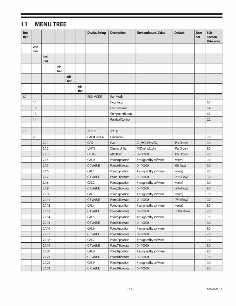
- 51 - 100.6605.19
11 MENU TREETop Tier
Display String Description Nomenclature / Value Default User Set
Sub-Section Reference
2nd Tier
3rd Tier
4th Tier
5thTier
6th Tier
1.0 RUN MODE Run Mode
1.1 Flow Pace 6.1
1.2 Feed Forward 6.4
1.3 Compound Loop 6.3
1.4 Residual Control 6.2
2.0 SET UP Set up
2.1 CALIBRATION Calibration 9.0
2.1.1 GAS Gas CL2/SO2/NH3/CO2 (Per Order) 9.0
2.1.2 UNITS Display Units PPD/g/hr/kg/hr (Per Order) 9.0
2.1.3 HI FLO Max flow 0 – 10000 (Per Order) 9.0
2.1.4 CAL 0 Point 0 position # assigned by software (varies) 9.0
2.1.5 C 0 VALUE Point 0 flowrate 0 – 10000 (0% flow) 9.0
2.1.6 CAL 1 Point 1 position # assigned by software (varies) 9.0
2.1.7 C 1 VALUE Point 1 flowrate 0 – 10000 (25% Flow) 9.0
2.1.8 CAL 2 Point 2 position # assigned by software (varies) 9.0
2.1.9 C 2 VALUE Point 2 flowrate 0 – 10000 (50% Flow) 9.0
2.1.10 CAL 3 Point 3 position # assigned by software (varies) 9.0
2.1.11 C 3 VALUE Point 3 flowrate 0 – 10000 (75% Flow) 9.0
2.1.12 CAL 4 Point 4 position # assigned by software (varies) 9.0
2.1.13 C 4 VALUE Point 4 flowrate 0 – 10000 (100% Flow) 9.0
2.1.14 CAL 5 Point 5 position # assigned by software 9.0
2.1.15 C 5 VALUE Point 5 flowrate 0 – 10000 9.0
2.1.16 CAL 6 Point 6 position # assigned by software 9.0
2.1.17 C 6 VALUE Point 6 flowrate 0 – 10000 9.0
2.1.18 CAL 7 Point 7 position # assigned by software 9.0
2.1.19 C 7 VALUE Point 7 flowrate 0 – 10000 9.0
2.1.20 CAL 8 Point 8 position # assigned by software 9.0
2.1.21 C 8 VALUE Point 8 flowrate 0 – 10000 9.0
2.1.22 CAL 9 Point 9 position # assigned by software 9.0
2.1.23 C 9 VALUE Point 9 flowrate 0 – 10000 9.0
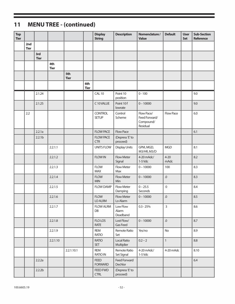
100.6605.19 - 52 -
11 MENU TREE - (continued)Top Tier
Display String
Description Nomenclature / Value
Default User Set
Sub-Section Reference
2nd Tier
3rd Tier
4th Tier
5thTier
6th Tier
2.1.24 CAL 10 Point 10 position
0 - 100 9.0
2.1.25 C 10 VALUE Point 10 flowrate
0 – 10000 9.0
2.2 CONTROL SETUP
Control Scheme
Flow Pace/ Feed Forward/ Compound/ Residual
Flow Pace 6.0
2.2.1a FLOW PACE Flow Pace 6.1
2.2.1b FLOW PACE CTR
(Depress 'E' to proceed)
2.2.1.1 UNITS FLOW Display Units GPM, MGD, M3/HR, M3/D
MGD 8.1
2.2.1.2 FLOW IN Flow Meter Signal
4-20 mAdc/1-5 Vdc
4-20 mAdc
8.2
2.2.1.3 FLOW MAX
Flow Meter Max
0 – 10000 100 8.3
2.2.1.4 FLOW MIN
Flow Meter Min
0 – 10000 .0 8.3
2.2.1.5 FLOW DAMP Flow Meter Damping
0 – 25.5 Seconds
0 8.4
2.2.1.6 FLOW LO ALRM
Flow Meter Lo Alarm
0 – 10000 .0 8.5
2.2.1.7 FLOW ALRM DB
Low Flow Alarm Deadband
0.3 - 25% 3 8.6
2.2.1.8 FLO LOS RATE
Lost Flow/ Gas Feed
0 – 10000 .0 8.7
2.2.1.9 REM RATIO
Remote Ratio Set
Yes/no No 8.9
2.2.1.10 RATIO SET
Local Ratio Multiplier
0.2 – 2 1 8.8
2.2.1.10.1 REM RATIO IN
Remote Ratio Set Signal
4-20 mAdc/1-5 Vdc
4-20 mAdc 8.10
2.2.2a FEED FORWARD
Feed Forward Dechlor
6.4
2.2.2b FEED FWD CTRL
(Depress 'E' to proceed)
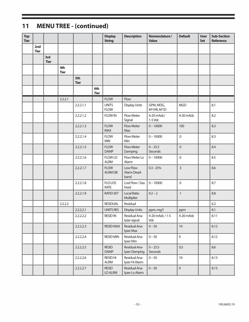
- 53 - 100.6605.19
11 MENU TREE - (continued)Top Tier
Display String
Description Nomenclature / Value
Default User Set
Sub-Section Reference
2nd Tier
3rd Tier
4th Tier
5thTier
6th Tier
2.2.2.1 FLOW Flow
2.2.2.1.1 UNITSFLOW
Display Units GPM, MDG, M3/HR, M3/D
MGD 8.1
2.2.2.1.2 FLOW IN Flow Meter Signal
4-20 mAdc/ 1-5 Vdc
4-20 mAdc 8.2
2.2.2.1.3 FLOW MAX
Flow Meter Max
0 – 10000 100 8.3
2.2.2.1.4 FLOW MIN
Flow Meter Min
0 – 10000 .0 8.3
2.2.2.1.5 FLOW DAMP
Flow Meter Damping
0 – 25.5 Seconds
0 8.4
2.2.2.1.6 FLOW LO ALRM
Flow Meter Lo Alarm
0 – 10000 .0 8.5
2.2.2.1.7 FLOW ALRM DB
Low Flow Alarm Dead-band
0.3 - 25% 3 8.6
2.2.2.1.8 FLO LOS RATE
Lost Flow / Gas Feed
0 – 10000 .0 8.7
2.2.2.1.9 RATIO SET Local Ratio Multiplier
0.2 – 2 1 8.8
2.2.2.2 RESIDUAL Residual 6.2
2.2.2.2.1 UNITS RES Display Units ppm, mg/l ppm 8.1
2.2.2.2.2 RESID IN Residual Ana-lyzer signal
4-20 mAdc / 1-5 Vdc
4-20 mAdc 8.11
2.2.2.2.3 RESID MAX Residual Ana-lyzer Max
0 – 50 10 8.12
2.2.2.2.4 RESID MIN Residual Ana-lyzer Min
0 – 50 0 8.12
2.2.2.2.5 RESID DAMP
Residual Ana-lyzer Damping
0 – 25.5 Seconds
0.5 8.6
2.2.2.2.6 RESID HI ALRM
Residual Ana-lyzer Hi Alarm
0 – 50 10 8.13
2.2.2.2.7 RESID LO ALRM
Residual Ana-lyzer Lo Alarm
0 – 50 0 8.13
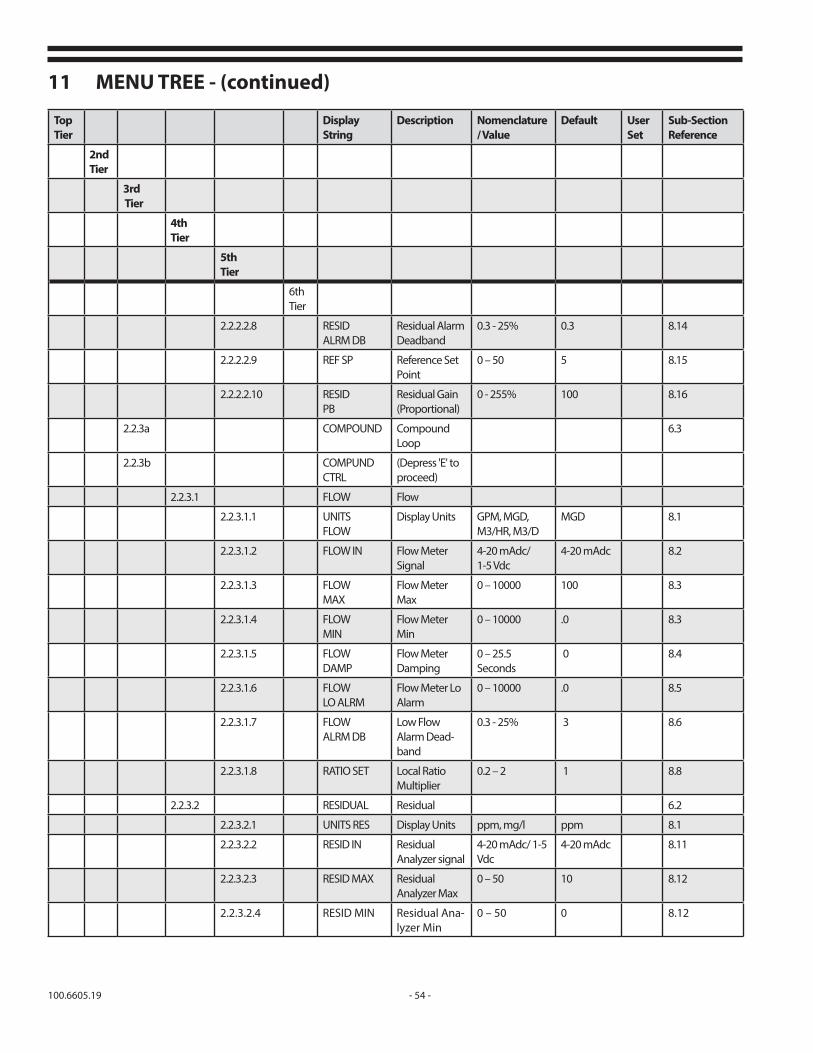
100.6605.19 - 54 -
11 MENU TREE - (continued)
Top Tier
Display String
Description Nomenclature / Value
Default User Set
Sub-Section Reference
2nd Tier
3rd Tier
4th Tier
5thTier
6th Tier
2.2.2.2.8 RESID ALRM DB
Residual Alarm Deadband
0.3 - 25% 0.3 8.14
2.2.2.2.9 REF SP Reference Set Point
0 – 50 5 8.15
2.2.2.2.10 RESID PB
Residual Gain (Proportional)
0 - 255% 100 8.16
2.2.3a COMPOUND Compound Loop
6.3
2.2.3b COMPUND CTRL
(Depress 'E' to proceed)
2.2.3.1 FLOW Flow
2.2.3.1.1 UNITS FLOW
Display Units GPM, MGD, M3/HR, M3/D
MGD 8.1
2.2.3.1.2 FLOW IN Flow Meter Signal
4-20 mAdc/ 1-5 Vdc
4-20 mAdc 8.2
2.2.3.1.3 FLOW MAX
Flow Meter Max
0 – 10000 100 8.3
2.2.3.1.4 FLOW MIN
Flow Meter Min
0 – 10000 .0 8.3
2.2.3.1.5 FLOW DAMP
Flow Meter Damping
0 – 25.5Seconds
0 8.4
2.2.3.1.6 FLOW LO ALRM
Flow Meter Lo Alarm
0 – 10000 .0 8.5
2.2.3.1.7 FLOW ALRM DB
Low Flow Alarm Dead-band
0.3 - 25% 3 8.6
2.2.3.1.8 RATIO SET Local Ratio Multiplier
0.2 – 2 1 8.8
2.2.3.2 RESIDUAL Residual 6.2
2.2.3.2.1 UNITS RES Display Units ppm, mg/l ppm 8.1
2.2.3.2.2 RESID IN Residual Analyzer signal
4-20 mAdc/ 1-5 Vdc
4-20 mAdc 8.11
2.2.3.2.3 RESID MAX Residual Analyzer Max
0 – 50 10 8.12
2.2.3.2.4 RESID MIN Residual Ana-lyzer Min
0 – 50 0 8.12
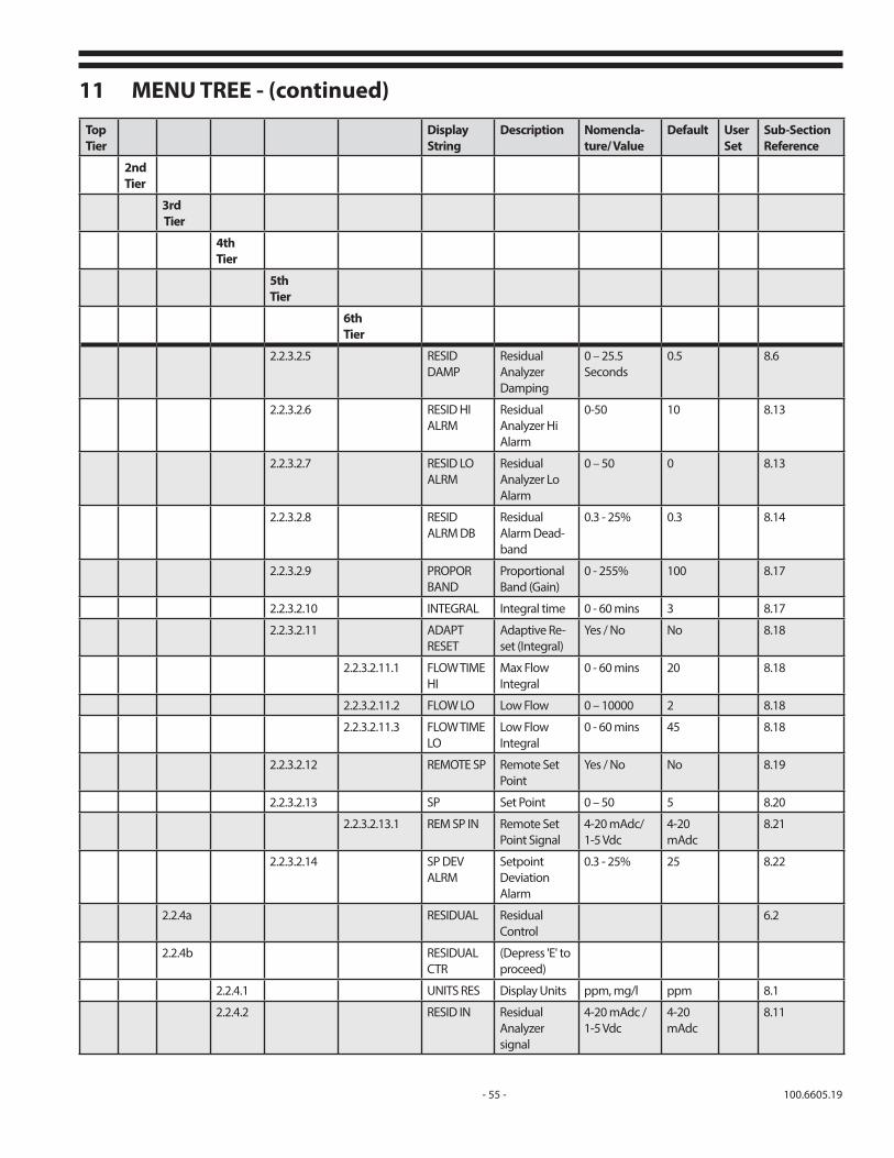
- 55 - 100.6605.19
11 MENU TREE - (continued)
Top Tier
Display String
Description Nomencla-ture/ Value
Default User Set
Sub-Section Reference
2nd Tier
3rd Tier
4th Tier
5thTier
6th Tier
2.2.3.2.5 RESID DAMP
Residual Analyzer Damping
0 – 25.5 Seconds
0.5 8.6
2.2.3.2.6 RESID HIALRM
Residual Analyzer HiAlarm
0-50 10 8.13
2.2.3.2.7 RESID LO ALRM
Residual Analyzer Lo Alarm
0 – 50 0 8.13
2.2.3.2.8 RESID ALRM DB
Residual Alarm Dead-band
0.3 - 25% 0.3 8.14
2.2.3.2.9 PROPOR BAND
Proportional Band (Gain)
0 - 255% 100 8.17
2.2.3.2.10 INTEGRAL Integral time 0 - 60 mins 3 8.17
2.2.3.2.11 ADAPT RESET
Adaptive Re-set (Integral)
Yes / No No 8.18
2.2.3.2.11.1 FLOW TIME HI
Max Flow Integral
0 - 60 mins 20 8.18
2.2.3.2.11.2 FLOW LO Low Flow 0 – 10000 2 8.18
2.2.3.2.11.3 FLOW TIME LO
Low Flow Integral
0 - 60 mins 45 8.18
2.2.3.2.12 REMOTE SP Remote Set Point
Yes / No No 8.19
2.2.3.2.13 SP Set Point 0 – 50 5 8.20
2.2.3.2.13.1 REM SP IN Remote Set Point Signal
4-20 mAdc/ 1-5 Vdc
4-20 mAdc
8.21
2.2.3.2.14 SP DEV ALRM
Setpoint Deviation Alarm
0.3 - 25% 25 8.22
2.2.4a RESIDUAL Residual Control
6.2
2.2.4b RESIDUAL CTR
(Depress 'E' to proceed)
2.2.4.1 UNITS RES Display Units ppm, mg/l ppm 8.1
2.2.4.2 RESID IN Residual Analyzer signal
4-20 mAdc / 1-5 Vdc
4-20 mAdc
8.11

100.6605.19 - 56 -
11 MENU TREE - (continued)Top Tier
Display String
Description Nomenclature/ Value
Default User Set
Sub-Section Reference
2nd Tier
3rd Tier
4th Tier
5thTier
6th Tier
2.2.4.3 RESIDMAX
Residual Analyzer Max
0-50 10 8.10
2.2.4.4 RESIDMIN
ResidualAnalyzer Min
0-50 0 8.12
2.2.4.5 RESID DAMP
Residual Analyzer Damping
0 – 25.5 Seconds
0.5 8.6
2.2.4.6 RESIDHI ALRM
Residual Ana-lyzer Hi Alarm
0 – 50 10 8.13
2.2.4.7 RESID LO ALRM
Residual Ana-lyzer Lo Alarm
0 – 50 0 8.13
2.2.4.8 RESID ALRM DB
Residual Alarm Deadband
0.3 - 25% 0.3 8.14
2.2.4.9 PROPOR BAND
Proportional Band (Gain)
0 - 255% 100 8.17
2.2.4.10 INTEGRAL Integral time 0 - 60 mins 3 8.17
2.2.4.11 REMOTE SP Remote Set Point
Yes / No No 8.19
2.2.4.12 SP Set Point 0 – 50 5 8.20
2.2.4.12.1 REM SP IN
Remote Set Point Signal
4-20 mAdc/ 1-5 Vdc
4-20 mAdc
8.21
2.2.4.13 SP DEV ALRM
Setpoint Deviation Alarm
0.3 - 25% 25 8.22
2.3 CONTACT INPUT
Contact Inputs 8.23
2.3.1 VAC SW ACTIVE
Vacuum Switch Enable
Yes / No No 8.24
2.3.1.1 VAC CONFIG
Vacuum Switch Con-figuration
NO / NC NC 8.25
2.3.1.2 VAC SW SET Vacuum Switch Fault Action
Lock / Drive to Zero
Lock 8.26
2.3.2 STBY SW ACTIVE
Standby Enable
Yes / No No 8.27

- 57 - 100.6605.19
11 MENU TREE - (continued)
Top Tier
Display String
Description Nomenclature/ Value Default User Set
Sub-Section Reference
2nd Tier
3rd Tier
4th Tier
5thTier
6th Tier
2.3.2.1 STBY CON-FIG
Standby Switch Configuration
NO / NC NO 8.28
2.4 OUTPUT RELAYS
Output Relays 8.29
2.4.1 R1 ASSIGN Relay 1 Assignment
NONE, STANDBY, VACUUM SWITCH, STALL, VALVE POS LOW, VALVE POS HIGH, WATER FLOW LOW, SET PT DEV LOW, SET PT DEV HIGH, RESIDUAL LOW, RESIDUAL HIGH, MANUAL, AUTO, REMOTE, LOCAL, FAULT
NONE 8.30
2.4.2 R1 CONF Relay 1 Configuration
NO/ NC NO 8.31
2.4.3 R2 ASSIGN Relay 2 Assignment
NONE, STANDBY, VACUUM SWITCH, STALL, VALVE POS LOW, VALVE POS HIGH, WATER FLOW LOW, SET PT DEV LOW, SET PT DEV HIGH, RESIDUAL LOW, RESIDUAL HIGH, MANUAL, AUTO, REMOTE, LOCAL, FAULT
NONE 8.30
2.4.4 R2 CONF Relay 2 Configuration
NO/ NC NO 8.31
2.4.5 R3 ASSIGN Relay 3 Assign-ment
NONE, STANDBY, VACUUM SWITCH, STALL, VALVE POS LOW, VALVE POS HIGH, WATER FLOW LOW, SET PT DEV LOW, SET PT DEV HIGH, RESIDUAL LOW, RESIDUAL HIGH, MANUAL, AUTO, REMOTE, LOCAL, FAULT
NONE 8.30
2.4.6 R3 CONF Relay 3 Configu-ration
NO/ NC NO 8.31
2.5 DEFAULTS Defaults 7.11
2.5.1 LOAD CUS DEF
Load Customer Defaults
Yes / No No 7.11

100.6605.19 - 58 -
11 MENU TREE - (continued)
Top Tier
Display String
Description Nomenclature/ Value Default User Set
Sub-Section Reference
2nd Tier
3rd Tier
4th Tier
5thTier
6th Tier
2.5.2 SET CUS DEFS Save Current Settings
Yes / No No 7.10
2.5.3 LOAD FAC DEFS
Load Factory Defaults
Yes / No No 7.10
2.5.4 PASS PROTECT
Password Pro-tection
Yes / No No 7.10
2.5.5 SET PASS Set New Password
Yes / No No 7.10
2.5.6 PASSWORD Enter Password
Enter 4 letters any combination
---- 7.10
2.5.7 INVERT DISPLAY
Invert Display
------ No 7.3
2.5.8 HYSTER CNT Hystersys Count
Factory set - do not change
2 7.10
2.5.9 DEADBAND CT
Deadband Count
Factory set - do not change
6 7.10
3.0 DIAGNOSTICS Diagnostics (Monitor only, no user inputs)
7.11
3.1 MOTOR STAT Motor State OFF / INC / DEC 7.11
3.2 AMP TEMP Amplifier Temperature
0-100 Deg. C 7.11
3.3 ACT STATUS Actuator State
0 - 65535 7.11
3.4 ACT STARTS Actuator Starts
0 - 65535 7.11
3.5 AMP STARTS Amplifier Starts
0 - 65535 7.11
3.6 STALL TO Stall Timeout 0 – 120 Seconds(Factory Fixed)
7.11
3.7 STALL CYCLES Stall Cycles 3 (Factory Fixed) 7.11
3.8 SOFT VER-SION
Software Ver-sion
V #.## 7.11
4.0 ALARMS Alarms Using 'U' & 'D' keys allows polling of all ac-tive alarms applicable to the active mode of operation
7.12

- 59 - 100.6605.19
Top Tier
Display String
Description Nomenclature/ Value Default User Set
Sub-Section Reference
2nd Tier
3rd Tier
4th Tier
5thTier
6th Tier
4.1 Alarm List NONE, STALL, VALVE POS LOW, VALVE POS HIGH, WATER FLOW LOW, LOS-FLOW, LOS-RESID, LOS-RM SET PT, LOS-POSITION, SET PT DEV LOW, SET PT DEV HIGH, RESIDUAL LOW, RESIDUAL HIGH, FAULT
8.3.2
11 MENU TREE - (continued)

100.6605.19 - 60 -

- 61 - 100.6605.19
12 TROUBLESHOOTING THE AUTOMATIC CONTROL VALVEThere are only a few malfunctions that can be remedied by the operator these are listed below. Most problems should be referred to a De Nora Water Technologies representative. Note that you should reference the model number and serial in all communications concerning this equipment.
PROBLEM PROBABLE CAUSE CORRECTIVE ACTION
1. Display is not lit with power applied.
Check fuses. Replace fuses as required.
2. Red LED located on rear of main circuit board is flashing at an approximate 1 second rate.
Valve control software is active and func-tioning.
Normal operation - None required
3. Required gas feed is not achieved at start-up.
a. Insufficient ejector vacuum from insufficient water supply pressure for existing back pressure.b. Vacuum leakage at vacuum line connection(s) or split vacuum line.
c. Vacuum piping exceeds maximum distance.
a. Refer to applicable ejector instruction manual.
b. Inspect connections and remake as necessary. Inspect vacuum line and replace as necessary.c. Refer to technical bulletin 121.3003.
4. Required gas flow rate is not achieved with the valve open.
a. Insufficient ejector vacuum.
b. Vacuum leakage at vacuum line connection(s) or split vacuum line.
a. Refer to applicable ejector instruction manual. b. Inspect connections and remake as necessary. Inspect vacuum line and replace as necessary.
5. After an operational period, the gas flow reading on the valve indicator does not agree with the rate meter indication.
Dirt deposits on the valve plug or a scored valve seat caused by less than a pure gas supply.
Refer to the maintenance section for cleaning procedure. Examine the plug and seat. If damage is evident after cleaning, replace the valve plug and/or seat and recharacterize the valve.
6. Gas leaking from gas supply pressure connec- tions.
Loose connection or faulty connection gasket seal.
Using 26 Deg. Baume’ ammonia solution vapor check each pressure connection and tighten or replace the gaskets as required.
7. Gas leaking from Vacuum Regulator vent and/or system vacuum lines.
Dirt on vacuum regulator inlet valve. Refer to the appropriate vacuum regulator instruction bulletin for cleaning and maintenance details.
8. During recalibration, the actuator would not accept the next higher setting.
The valve assigned by the actuator for that point is lower than the new setting.
Start the calibration at 100% of max and proceed down scale to zero.

100.6605.19 - 62 - FEB 2017
Represented by:Design improvements may be made without notice.
De Nora Water Technologies3000 Advance Lane Colmar, PA 18915 ph +1 215 997 4000 • fax +1 215 997 4062 web: www.denora.commail: [email protected]
®Registered Trademark. © 2017. All Rights Reserved.