Embed Size (px)
Citation preview

RIGGING & ASSEMBLY INSTRUCTIONS
Series 3000 and XE-Series Cooling Towers
Series 3000
XE-Series 3000

Series 3000 and XE-Series Cooling Towers should be
rigged and assembled as outlined in this bulletin.
These procedures should be thoroughly reviewed prior to the
actual rigging and assembly of the equipment to acquaint all
personnel with procedures to be followed and to assure that all
necessary equipment will be available beforehand.
Be sure to have a copy of the certified drawing available for reference. If
you do not have a copy of this drawing, or if you need additional information
about this unit, contact your local BAC Representative whose name and
telephone number are on a label adjacent to the access door. The model
number and serial number of the unit are also located in this area.

WWW.BALTIMOREAIRCOIL .COM
1
Table of ContentsRIGGING & ASSEMBLY INSTRUCTIONS » SERIES 3000 AND XE-SERIES COOLING TOWERS
1 Introduction
2 Safety
2 Shipping
2 Pre-Rigging Checks
3 Unit Weights
3 Anchoring
3 Cold Weather Operation
3 Location
3 Warranties
3 Unit Operation
2 Unit Rigging & Assembly
4 Rigging
5 Single-Cell Installation
5 Two Piece Section Assembly
6 Multi-Cell Installation
6 Multi-Cell Unit Assembly
6 Flume Box Installation
8 Optional Positive Closure Plate Installation
9 Fan Guard Installation
9 One-Piece Fan Guard
10 Two-Piece Fan Guard
11 Four-Piece Fan Guard
13 Top Inlet Piping Installation
15 Motor Location and Conduit Installation
3 Optional Accessory Installation
16 Whisper Quiet Fan Installation
18 Side Outlet Depressed Sump Box Installation
19 Factory Pre-Wired Terminal Box
19 Optional Accessories and Equipment

WWW.BALTIMOREAIRCOIL .COM
2
SafetyAdequate precautions appropriate for the installation and location of these products should be taken to safeguard the equipment and the premises from damage and the public from possible injury. The procedures in this manual must be thoroughly reviewed prior to rigging and assembly. Read all dangers, warnings, cautions, and notes detailed in the margins.
When the fan speed of the unit is to be changed from the factory set speed, including the use of a variable speed device, steps must be taken to avoid operating at or near the fan’s “critical speed” which could result in fan failure and possible injury or damage. Consult with your local BAC Representative on any such applications.
ShippingBAC Cooling Towers are factory assembled to assure uniform quality and minimum field assembly. Models S3E/XES3E-8518-xxx, S3E/XES3E-1020-xxx, S3E/XES3E-1222-06x, S3E/XES3E-1222-07x, and S3E/XES3E-1424-07x ship in one section ship in one section. Models S3E/XES3E-1222-10x through S3E/XES3E-1222-14x and S3E/XES3E-1424-12x through S3E/XES3E-1424-14x ship in two sections. For the dimensions and weights of a specific unit or section, refer to the certified drawings.
Pre-Rigging ChecksWhen the unit is delivered to the jobsite, it should be checked thoroughly to ensure all required items have been received and are free of any shipping damage prior to signing the bill of lading.
The following parts should be inspected: � Sheaves and Belts / Gearbox
� Bearings
� Bearing Supports
� Fan Motor(s)
� Fan(s) and Fan Shaft(s)
� Float Valve Assembly(s)
� Water Distribution System
� Fill
� Cold Water Basin Accessories
� Interior Surfaces
� Exterior Surfaces
� Optional EASY CONNECT® Piping Arrangement (when provided)
� Louvers / Combined Inlet Shields
� Optional Air Inlet Screens (when provided)
� Mating Surfaces Between Sections /Modules
� Miscellaneous Items: All bolts, nuts, washers, and sealer tape required to assemble sections or component parts are furnished by BAC and shipped with the unit. A checklist inside the envelope marked “Customer Information Packet” indicates what miscellaneous parts are included with the shipment and where they are packed. This envelope will be attached to the side of the unit or located in a box inside the unit.
SERIES 3000 COOLING TOWER
Introduction1WARNING: Failure to use lifting
provisions can result in a dropped
load causing severe injury, death,
and/or property damage. Lifts
must be performed by qualified
riggers following BAC published
Rigging Instructions, and generally
accepted lifting practices. The
use of a supplemental safety
sling may also be required if the
lift circumstances warrant its
use, as determined by the rigging
contractor.
CAUTION: Only personnel qualified
to do so should undertake
operation, maintenance and repair
of this equipment. Proper care,
procedures and tools must be used
in handling, lifting, installing,
operating, maintaining and
repairing this equipment to prevent
personal injury and/or property
damage.

WWW.BALTIMOREAIRCOIL .COM
3
SERIES 3000 COOLING TOWER
IntroductionUnit WeightsBefore rigging any unit, the weight of each section should be verified from the unit certified drawing. Some accessories add additional weight as shown on the respective accessory drawings.
AnchoringSeven-eighths (7/8”) diameter holes are provided in the bottom flange of the basin section for bolting the unit to the support beams. Refer to the suggested support location drawing included in the submittal for location and quantity of the mounting holes. The unit must be level for proper operation. Anchor bolts must be provided by others. The IBC rating is only certified with standard anchorage locations. Using alternate anchorage locations or alternate steel supports will void any IBC wind or seismic ratings. Contact your local BAC Representative for details
Cold Weather OperationThese products must be protected by mechanical and operational methods against damage and/or reduced effectiveness due to possible freeze-up. Please refer to the Series 3000 Operation & Maintenance Manual on www.BaltimoreAircoil.com, or contact your local BAC Representative for recommended cold weather operation strategies.
LocationAll evaporative cooling equipment must be located to ensure an adequate supply of fresh air to the unit air intakes. When units are located adjacent to walls or in enclosures, care must be taken to ensure the warm, saturated, discharge air is not deflected and recirculated back to the air intakes.
Each unit should be located and positioned to prevent the introduction of discharge air into the ventilation system of any building. For detailed recommendations on BAC equipment layout, see our website at www.BaltimoreAircoil.com or contact your local Representative.
WarrantiesPlease refer to the Limitation of Warranties (located in the submittal package) applicable to and in effect at the time of the sale/purchase of these products.
Unit OperationPrior to start-up and unit operation, refer to the Series 3000 Operation & Maintenance Manual shipped with the unit and also available at www.BaltimoreAircoil.com
NOTE: Each unit must be located
and positioned to prevent the
introduction of discharge air
into the ventilation systems of
the building on which the unit is
located and of adjacent buildings.
ATTENTION: Before an actual lift
is undertaken, ensure no water,
snow, ice, or debris has collected
in the basin or elsewhere in the
unit. Such accumulations will add
substantially to the equipment’s
lifting weight.
Introduction
Safety
Shipping
Pre-Rigging ChecksUnit Weights
Anchoring
Cold Weather Operation
Location
Warranties
Unit Operation

WWW.BALTIMOREAIRCOIL .COM
4
RiggingRefer to Table 1 and Figures 1 and 2 for the required minimum spreader bar and the recommended vertical dimension “H” from the lifting device at the base of each unit or section to the spreader bar.
All single cell and multi cell units must be rigged one section at a time. Models S3E/XES3E-8518-x, 1020-x, 1222-06x, 1222-07x, and 1424-07x ship in one section per cell. All other models ship in two sections per cell.
Model Number
Dimensions (For Each Section)
Section Min. H Min. W1 Min W2
S3E/XES3E-8518-x One Section 15' 8'-6" 18'-1"
S3E/XES3E-1020-x One Section 17' 10' 20'-1"
S3E/XES3E-1222-06x, 1222-07x One Section 18' 12' 21'-7"
S3E/XES3E-1424-07x One Section 20' 14' 24'-1"
S3E/XES3E-1222-10x through S3E/XES3E-1222-14x Upper/Lower 18'/18' 12'/12' 21’-7”/21’-7”
S3E/XES3E-1424-12x through S3E/XES3E-1424-14x Upper/Lower 20'/20' 14'/14’ 24’-1”/24’-1”
H
SPREADER BAR
(Min.)
W1
Lifting Cable
SafetySlings
Lifting Device ForThis Section Only
(Min.)
W1
Spreader Bar
Lifting Cable
H
Lifting Device ForThis Section Only
Do Not Use ForFinal Positioning Of
Assembled Cell
Spreader Bar
LowerSection
SafetySlings
Lifting Device LocationMust be Used forFinal Positioning ofMulti-Cells
Spreader Bar(Min.)
W2
H
Safety Slings
Lifting Device
Lifting Rig
LowerSectionShown
Figure 1. Lifting Instruction for Single-Cell Units:One Section Cells or Two Section Cells (Upper Section Shown)
Figure 2. Lifting Instruction for Multi Cell Units: :One Section Cells or Two Section Cells (Lower Section Shown)
Table 1. Minimum Vertical Dimension and Spreader Bar Length
SERIES 3000 COOLING TOWER
Unit Rigging & Assembly2
NOTE: For weight information refer to
the submittal drawing package.
WARNING: Failure to use lifting
provisions can result in a dropped
load causing severe injury, death,
and/or property damage. Lifts
must be performed by qualified
riggers following BAC published
Rigging Instructions, and generally
accepted lifting practices. The
use of a supplemental safety
sling may also be required if the
lift circumstances warrant its
use, as determined by the rigging
contractor.

WWW.BALTIMOREAIRCOIL .COM
5
Unit Rigging & Assembly
Rigging
Single-Cell InstallationTwo Piece Section Assembly
Single-Cell Installation
Two Piece Section Assembly1. Remove any accessories shipped in the cold water basin.
2. Position the lower section on the unit supports and bolt in place.
3. Wipe any moisture and dirt from the perimeter mating flanges of the lower section.
4. Install foam seal tape (BAC part # 270175) supplied with the unit, as illustrated in Figure 3, on the mating flanges of the lower section in a continuous line. At each corner, allow 1” overlap.
5. Complete assembly using the external bolt holes as guides for alignment:
– Before lowering the upper section onto the lower section, be sure to line up the bolt holes using drift pins as illustrated in Figure 5, no fewer than one hole at each edge. Guide the upper section onto the lower section starting with a bolt hole at one corner and following down the flange.
– Match marks must line up as shown in Figure 3.
– Secure the upper section in place as shown in Figure 4 to ensure leak-free operation.
Figure 5. Drift Pin Alignment
Figure 4. Typical Bolting
NOTE: 1/2” bolts, flat washers, and
lock washers are used.
Foam Seal
Tape
Flat Washer, Lock Washer,
and Nut
1/2” Bolt
1/2” Flat
Washer
Match Marks
Figure 3. Upper and Lower Assembly for Series 3000 Cooling Towers

WWW.BALTIMOREAIRCOIL .COM
6
Multi-Cell InstallationRefer to the submittal drawings for the proper orientation of each cell. The number and “face” are stenciled on the outer basin wall. Multi-cell cooling tower installations may employ flume boxes to equalize the water level in the basin of each cell. Follow directions in “Flume Box Installation” for details on their installation.
Multi-Cell Unit Assembly1. First, position the lower section of all cells on the unit supports and bolt in place.
Some units come furnished with a flume box. If they do, use the flume box assembly procedure outlined in “Flume Box Installation” to connect the basins of the multi-cell units.
2. Wipe any moisture and dirt from the perimeter mating flanges.
3. Install foam seal tape (BAC part # 270175) supplied with the unit, as illustrated in Figure 3, on page 5 on the mating flanges of the lower sections in a continuous line. At each corner, allow 1” overlap.
4. Complete assembly using the internal drift pin alignment guides:
– Using drift pins in the drift pin guides provided (Figure 7), guide the top section on to the bottom section.
– Match marks must line up as shown in Figure 3 on page 5.
– Bolt the top sections onto the bottom sections as shown in Figure 4 on page 5 using the bolting channels in Figure 6.
Flume Box Installation
1. Position Cell #1 on the unit support and bolt in place.
2. Wipe down the surface adjacent to the flume opening of Cell #1 to remove any dirt or moisture that may have accumulated during shipment.
3. Wipe down the flanges on both ends of the flume box. On one end, apply a layer of flat butyl sealer tape (BAC part # 554000) around the face of the flange over the centerline of the holes. Do not overlap or stretch too thinly at the corners. When it is necessary to splice the sealer tape, be sure to press the two ends together to form a smooth, continuous strip. Apply a second layer of flat butyl sealer tape over the first layer following the same procedure. Refer to Figure 8, Detail A.
4. Using drift pins to align the bolt holes, place the flume box over the opening in the basin of Cell #1.
5. Fasten into place as shown in Figure 9. For basins with TriArmor® Corrosion Protection System, backing plates are to be installed inside the basin and flume box opening (see Figure 10, Detail A). Insert the 3/8” self-tapping screws or bolts in each hole from the flume box into the basin wall and backing strips (if applicable) as illustrated in Figure 10.
NOTE: Flume boxes furnished
with units constructed with
TriArmor® Corrosion Protection
System or stainless steel basins
are assembled with stainless
steel bolts, washers and nuts
in lieu of self tapping screws.
Before installing the nuts, apply a
lubricant to the bolts to reduce the
potential for seizing.
Figure 6. Upper and Lower Assembly - Drift Pin Guides
Drift Pin Guides
Figure 7. Bolting Channels
Bolting Channels

WWW.BALTIMOREAIRCOIL .COM
7
Unit Rigging & Assembly
Multi-Cell InstallationMulti-Cell Unit Assembly
Flume Box Installation
Cell #1
Cell #2
Figure 8. Flume Box Installation2 Layers Of Flat Sealer Tape
Apply Flat Sealer Tape Over The Center Line of the Bolt Holes
Detail A
NOTE: For cold water basins
constructed with the TriArmor®
Corrosion Protection System, attach
the vertical and horizontal backing
plates as shown in Figure 10,
Detail A.
2 Layers of FlatButyl Sealer Tape
A
A
Cell #1
Cell #2
3/8" S.T. Screw2 Layers of Flat
Butyl Sealer Tape
Flume Box
Cell #1 Cell #2
2 Layers of FlatButyl Sealer Tape
Figure 9. Expanded View
Figure 10. Elevation View
2 Layers of FlatButyl Sealer Tape
A
A
Cell #1
Cell #2
3/8" S.T. Screw2 Layers of Flat
Butyl Sealer Tape
Flume Box
Cell #1 Cell #2
2 Layers of FlatButyl Sealer Tape
2 Layers of Flat Butyl Sealer Tape
SST 3/8 X 1/4Bolt (Typ.)
Flume BoxBacking Plates Used on TriArmor® Basins Only
SST 3/8 Flatwasher (Typ.)
No Sealer BetweenBacking Platesand Basin Wall Basin Wall
Detail A. For Units with TriArmor® Corrosion Protection System Only
6. Apply two layers of flat butyl sealer tape to the other end of the flume box.
7. Wipe down the surface adjacent to the flume opening of Cell #2 to remove any dirt or moisture. Position Cell #2 on the unit supports.
8. Using drift pins to assure alignment, draw Cell #2 tight against the flume box.
9. Repeat Step 5 to fasten the flume box to Cell #2.

WWW.BALTIMOREAIRCOIL .COM
8
Positive Closure Plate InstallationThe optional positive closure plate and gasket can be furnished on multi-cell units to allow individual cells to be isolated for cleaning and routine maintenance. The plate ships loose inside the cold water basin.
1. Remove nuts and flat washer from the flume box.
2. Position the neoprene gasket and positive closure plate over the bolts and fasten in place with 3/8” wing nut and flat washers.
3. When the cooling tower operation does not require use of the positive closure plate, remove the closure plate and gasket. Retighten the flume box using the wing nuts and flat washers.
2 Layers of Flat Butyl Sealer Tape
B
B
Cell #1
Cell #2
Neopren
e
Gasket
Positive
Closure P
late
3/8" Flatwasher
3/8" Wing Nut
2 Layers of Flat Butyl Sealer Tape 3/8" S.T.Screw
3/8" SelfCutting Bolt
Neoprene Gasket
Positive Closure PlateFlume Box
Cell #1 Cell #2
2 Layers of Flat Butyl Sealer Tape
2 Layers of Flat Butyl Sealer Tape
B
B
Cell #1
Cell #2
Neopren
e
Gasket
Positive
Closure P
late
3/8" Flatwasher
3/8" Wing Nut
2 Layers of Flat Butyl Sealer Tape 3/8" S.T.Screw
3/8" SelfCutting Bolt
Neoprene Gasket
Positive Closure PlateFlume Box
Cell #1 Cell #2
2 Layers of Flat Butyl Sealer Tape
Figure 11. Expanded View
Figure 12. Elevation View

WWW.BALTIMOREAIRCOIL .COM
9
Unit Rigging & Assembly
Multi-Cell InstallationOptional Positive Closure Plate
Fan Guard InstallationOne-Piece Fan Guard
Fan Guard InstallationDue to height limitations on truck shipments, the fan guard may ship unmounted. Never step or walk on the fan guard when installed. Refer to Table 2 for the number of fan guard pieces Series 3000 Cooling Towers will have .
DANGER: Fan guard must be
securely in place before the cooling
tower is placed in operation. Never
step or walk on the fan guard.
NOTE: 1. Existing 3/8” stud and nut for
guard mounting at fan deck level (3/8” x 1 1/2” bolt for guards mounted on top of cowl extensions).
Figure 13. One-Piece Fan Guard Assembly
See Detail A
Detail A
Fan Guard Clip
3/8" Locknut
See Note 1
Fan Guard
Model NumberNumber of Fan Guard Pieces
S3E/XES3E-8518-xxx 1
S3E/XES3E-1020-xxx, 1222-xxx, 1424-07x 2
S3E/XES3E-1424-12x, 1424-13x, 1424-14x 4
Table 2. Number of Fan Guard Pieces
One-Piece Fan GuardMount fan guard to unit as illustrated in Figure 13, Detail A.
WWW.BALTIMOREAIRCOIL .COM
10
See Detail C(All Except Seam)
See Detail A(At Seam Only)
See Detail B
See Detail B
XY
Y
X
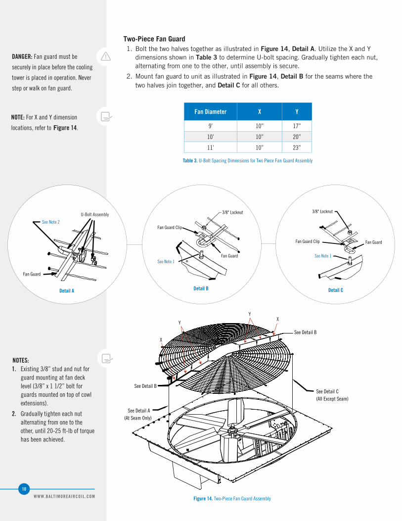
Figure 14. Two-Piece Fan Guard Assembly
Fan Diameter X Y
9’ 10” 17”
10’ 10” 20”
11’ 10” 23”
Table 3. U-Bolt Spacing Dimensions for Two Piece Fan Guard Assembly
See Note 2
Fan Guard
U-Bolt Assembly
Fan Guard Clip
3/8" Locknut
See Note 1
Fan Guard
Detail A Detail B Detail C
NOTES: 1. Existing 3/8” stud and nut for
guard mounting at fan deck level (3/8” x 1 1/2” bolt for guards mounted on top of cowl extensions).
2. Gradually tighten each nut alternating from one to the other, until 20-25 ft-lb of torque has been achieved.
NOTE: For X and Y dimension
locations, refer to Figure 14.
Two-Piece Fan Guard1. Bolt the two halves together as illustrated in Figure 14, Detail A. Utilize the X and Y
dimensions shown in Table 3 to determine U-bolt spacing. Gradually tighten each nut, alternating from one to the other, until assembly is secure.
2. Mount fan guard to unit as illustrated in Figure 14, Detail B for the seams where the two halves join together, and Detail C for all others.
DANGER: Fan guard must be
securely in place before the cooling
tower is placed in operation. Never
step or walk on fan guard.
See Note 1
3/8" Locknut
Fan Guard
Fan Guard Clip

WWW.BALTIMOREAIRCOIL .COM
11
Unit Rigging & Assembly
Fan Guard InstallationTwo-Piece Fan Guard
Four-Piece Fan Guard
Fan GuardSupport Fan Guard
Support
3/8" x 1" Bolt
3/8" Flatwasher
3/8" Flatwasher3/8" Locknut
Fan Guard Plate
Fan Guard Clip
3/8" Locknut
See Note 1
Fan Guard
Detail A Detail B Detail C
See Detail C
See Detail A ForFastening the Fan Guard
to the Fan Screen Support
See Detail B
Figure 15. Four-Piece Fan Guard Assembly
DANGER: Fan guard must be
securely in place before the cooling
tower is placed in operation. Never
step or walk on the fan guard.
Four-Piece Fan Guard1. Assemble fan guard supports as illustrated in Figure 15, Detail A.
2. Secure fan guard pieces to fan guard supports as shown in Figure 15, Detail B.
3. Mount fan guard assembly to unit as shown in Figure 15, Detail C.
Fan Clip Guard3/8" x 1 1/2" Bolt
3/8" Flatwasher
3/8" Locknut
Fan Guard Fan Guard Support
NOTE: 1. Existing 3/8” stud and nut for
guard mounting at fan deck level (3/8” x 1 1/2” bolt for guards mounted on top of cowl extensions).

WWW.BALTIMOREAIRCOIL .COM
12
See Note 10
Pipe Support Location See Figure 18, Detail A
C (Typ. Per Cell)
Water Inlet(See Unit Print For Size) See Figure 18, Detail C
Pipe Support Location See Figure 18, Detail A
See Note 5
Plan View
Elevation View
Sta
tic
Lift
B
A
AA 2
2
H
HHHH 2
2
Top Inlet Piping InstallationUse the following drawings, notes, and tables when installing top inlet piping. Drawings shown are for multi-cell installations. For single cell installations, simply ignore the additional cells and dimension “C” from Table 4.
Figure 16. Single Riser Piping Schematic
Table 4. Dimensions for Series 3000 Piping Schematic
Model Number A B C H
S3E/XES3E-8518-05x 10’-6 3/4" 4’-2 7/8" 8’-8 1/4" 8’-7 3/4"
S3E/XES3E-8518-06x 10’-6 3/4" 4’-2 7/8" 8’-8 1/4" 9’-11 3/4"
S3E/XES3E-8518-07x 10’-6 3/4" 4’-2 7/8" 8’-8 1/4" 11'-3 3/4"
S3E/XES3E-1020-06x 12’-6 3/4" 4’-10 5/8" 9’-11 3/4" 9’-11 3/4"
S3E/XES3E-1020-07x 12’-6 3/4" 4’-10 5/8" 9’-11 3/4" 11’-3 3/4"
S3E/XES3E-1222-06x 14’-0 3/4" 5’-10 7/8" 12’-0 1/4" 9’-11 3/4"
S3E/XES3E-1222-07x 14’-0 3/4" 5’-10 7/8" 12’-0 1/4" 11’-3 3/4"
S3E/XES3E-1222-10x 14’-0 3/4" 5’-10 7/8" 12’-0 1/4" 15’-5 1/2"
S3E/XES3E-1222-12x 14’-0 3/4" 5’-10 7/8" 12’-0 1/4" 18’-1 1/2"
S3E/XES3E-1222-13x 14’-0 3/4" 5’-10 7/8" 12’-0 1/4" 19'-5 3/4"
S3E/XES3E-1222-14x 14’-0 3/4" 5’-10 7/8" 12’-0 1/4" 20’-9 1/2"
S3E/XES3E-1424-07x 16’-6 3/4" 6’-11 9/16" 14’-1 5/8" 11’-3 3/4"
S3E/XES3E-1424-12x 16’-6 3/4" 6’-11 9/16" 14’-1 5/8" 18’-1 1/2"
S3E/XES3E-1424-13x 16’-6 3/4" 6’-11 9/16" 14’-1 5/8" 19'-5 3/4"
S3E/XES3E-1424-14x 16’-6 3/4" 6’-11 9/16" 14’-1 5/8" 20’-9 1/2"
Table 5. Flow Control Valve
NOTES FOR FIGURE 16:
1. All piping shown by dashed lines is to be furnished by others. Refer to the certified unit print for details on the cooling tower.
2. Field piping should be fabricated at the time of unit installation. Pre-fabrication of pipe work is not recommended.
3. Required static pumping head from base of cooling tower is indicated by static lift dimension and piping friction losses.
4. When tower is equipped with safety railing package, inlet piping should be designed to clear the railing. Adjust static lift as required.
5. For units installed on vibration isolation rails (provided by others), flexible connections should be installed in the piping just before the tower perimeter.
6. All piping supports to be designed, furnished, and installed by others.
7. Supply piping to cooling tower inlet connections may be supported from the tower structure only at the pipe support locations shown. Piping must not be supported by the tower inlet connections. Piping outside the perimeter of the tower must not be supported from the tower.
8. Supply piping supports must be designed to rest on the walls of the hot water distribution basins at locations indicated (see Figure 18, Detail A).
9. Maximum diameter of inlet header piping that can be supported by the cooling tower distribution basins is 14”.
10. Provide adequate space between cooling tower and riser piping to allow for entry into the cooling tower access doors.
Size Width
6” 2 1/4”
8” 2 1/2”
10” 2 13/16”

WWW.BALTIMOREAIRCOIL .COM
13
Unit Rigging & Assembly
Top Inlet Piping Installation
Figure 16. Single Riser Piping Schematic
Figure 17. Dual Riser Piping Schematic
Plan View
Elevation View
C (Typ. Per Cell)
Water Inlet(See Unit Print For Size)See Figure 18, Detail C
See Note 5
Sta
tic
Lift
BA
HNOTES FOR FIGURE 17:
1. All piping shown by dashed lines is to be furnished by others. Refer to the certified unit print for details on the cooling tower.
2. Field piping should be fabricated at the time of unit installation. Pre-fabrication of pipe work is not recommended.
3. Required static pumping head from base of cooling tower is indicated by static lift dimension and piping friction losses.
4. When tower is equipped with safety railing package, inlet piping should be designed to clear the railing. Adjust static lift as required.
5. For units installed on vibration isolation rails (provided by others), flexible connections should be installed in the piping just before the tower perimeter.
6. All piping supports to be designed, furnished, and installed by others.
7. Supply piping to the cooling tower inlet connections must not be supported from the tower.
Piping by others. Flow control valves available by BAC or others, and always installed by others.
1 1/2” x 12” (PLATE) AND PIPESUPPORT - (BY OTHERS)
DETAIL “A”PIPE SUPPORT AT END OF TOWER
(SEE NOTES 7 & 8)
DETAIL “B”PIPE SUPPORT BETWEEN TOWER
(SEE NOTES 7 & 8)
6 3/4” X 12” (PLATE)AND PIPE SUPPORT(BY OTHERS)
DETAIL “C”FACE OF WATER INLET AT HOT WATER
DISTRIBUTION BASIN
FACEOFWATERINLET
STUD PATTERN(BY BAC)
PIPING(BY OTHERS)
PIPINGBY OTHERS
FLOW CONTROLVALVE (BY BACOR OTHERS)
MIN. RECOMMENDED8” FROM FACE TOFACE OF FLANGE
Figure 18. Piping Drawing Details

WWW.BALTIMOREAIRCOIL .COM
14
Motor Location and Conduit InstallationUse the following drawings and notes when installing electrical conduit for cooling towers supplied with the BALTIDRIVE® Power Train, BALTIGUARD™ Fan System, or gear drives. Notice the table for weight adds for two-speed motors and the BALTIGUARD™ Fan System.
Weights given in Tables 6 and 7 represent the additional weight when an optional 2-speed motor or BALTIGUARD™ Fan System is ordered. These weights should be added to the standard unit weight.
BALTIGUARD™ Fan System Motor Weight Add
Motor HP Weight (lbs)
3 100
5 110
7.5 160
10 175
15 300
20 260
25 390
30 440
Table 6. 2-Speed Motor Weight Add[1]
Table 7. BALTIGUARD™ Fan System Motor Weight Add[2]
2-Speed Motor Weight Add
Motor HP Weight (lbs)
7.5 140
10 185
15 90
20 80
25 210
30 170
40 225
50 300
60 425
75 340
100 (gear only) 600
Figure 19. Belt Drive Motor Location(s) for Models that Ship in One Section
See Note 4on Page 14
Main FanMotor
OptionalBALTIGUARD™Fan System Motor
Face A
Face B
Face B
Face A
Face B
Face A
Face B
Face A
CT-
4C
T-3
CT-
2C
T-1
OptionalBALTIGUARD™
Fan System Motor
Main Fan Motor
Conduit Box
Flexible Conduit (Allow Sufficient Slack for Belt Tensioning)Rigid Conduit
Hole in Casing Panel Should be Large Enough to Accommodate ConduitSeal with Waterproof Sealant
Rigid Conduit Outside Tower Turned Down to Junction Box or Safety Switch
Disconnect/Safety Switch in Weatherproof Enclosure Must be Rated for Proper
Voltage and Horsepower of Fan Motor
Motor Detail for Main Motor (BALTIDRIVE® Power Train) or BALTIGUARD™ Fan System (If Ordered)
Connection End of Unit
Plan View
Number of Cells Configuration
1 CT-1
2 CT-1 & CT-4
3 CT-1, CT-2 & CT-4
4 CT-1 through CT-4
NOTES FOR FIGURES 19-21:
1. Conduit must be water tight and pitched downward to allow condensation to drain away from fan motor conduit box. Therefore, do not run the conduit through fan deck.
2. All wiring must conform to local and national electrical codes. Junction box/safety switch and all conduit from fan motor conduit box to be sized, provided, and installed by others.
3. Rigid conduit outside casing panel must turn down to junction box.
4. On multi-cell units, use separate conduit lines for each fan motor. Run conduit through adjacent cells to junction box and or disconnect switch on front/rear cell.
NOTE: 1. Weights given represent the
additional weight when a 2-speed motor is ordered and should be added to the standard unit weight.
2. If the optional BALTIGUARD™ Fan System is ordered, weights given are for each BALTIGUARD motor and should be added to the standard unit weight.

WWW.BALTIMOREAIRCOIL .COM
15
Figure 19. Belt Drive Motor Location(s) for Models that Ship in One Section
Figure 20. Belt Drive Motor Location(s) for Models that Ship in Two Sections
See Note 4on Page 14
Main FanMotor
OptionalBALTIGUARD™Fan System Motor
Face B
Face B
Face AFace B
Face AFace B
Face A
CT-
3C
T-2
CT-
1
Face A
CT-
4
Main Fan Motor
Conduit Box
Flexible Conduit (Allow Sufficient Slack for Belt Tensioning)
Conduit Box
Hole in Casing Panel Should be Large Enough to Accommodate ConduitSeal with Waterproof Sealant
Rigid Conduit Outside Tower Turned Down to Junction Box or Safety Switch
Disconnect/Safety Switch in Weatherproof Enclosure Must be Rated for Proper
Voltage and Horsepower of Fan Motor
Connection End of Unit
OptionalBALTIGUARD™Fan System Motor
Motor Detail for Main Motor (BALTIDRIVE® Power Train) or BALTIGUARD™ Fan System (If Ordered)
Plan View
Number of Cells Configuration
1 CT-1
2 CT-1 & CT-4
3 CT-1, CT-2 & CT-4
4 CT-1 through CT-4
Figure 22. External Fan Motor Location for Gear Drive
See Note 4on Page 14
Fan Motor
Face B
Face AFace B
Face AFace B
Face AFace B
Face A
CT-
4C
T-3
CT-
2C
T-1
Fan Motor
Rigid Conduit
Hole in Casing Panel Should be Large Enough toAccommodate ConduitSeal with Waterproof Sealant
Rigid Conduit Outside Tower Turned Down to Junction Box or Safety Switch
Disconnect/Safety Switch in Weatherproof Enclosure Must be Rated for Proper
Voltage and Horsepower of Fan Motor
Close-Coupled Gear Drive Motor Detail
ConnectionEnd of Unit
Plan View
Conduit Box
Fan Motor
Rigid Conduit Outside Tower Turned Down to Junction Box or Safety Switch
Disconnect/Safety Switch in Weatherproof Enclosure Must be
Rated for Proper Voltage and Horsepower of Fan Motor
ConnectionEnd of Unit
Conduit Box Drive Shaft
Rigid Conduit
Mounting Base
External motor, mounting base and drive shaft must be field-installed. Drive shaft must also be properly aligned after installation by qualified personnel to ensure
satisfactory operation.
Face A
Face B
Face A
Face B
CT-
2C
T-1
Fan Motor
Plan View
External Fan Motor Detail
Number of Cells Configuration
1 CT-1
2 CT-1 & CT-4
3 CT-1, CT-2 & CT-4
4 CT-1 through CT-4
Figure 21. Motor Location For Close-Coupled Gear Drive
WWW.BALTIMOREAIRCOIL .COM
16
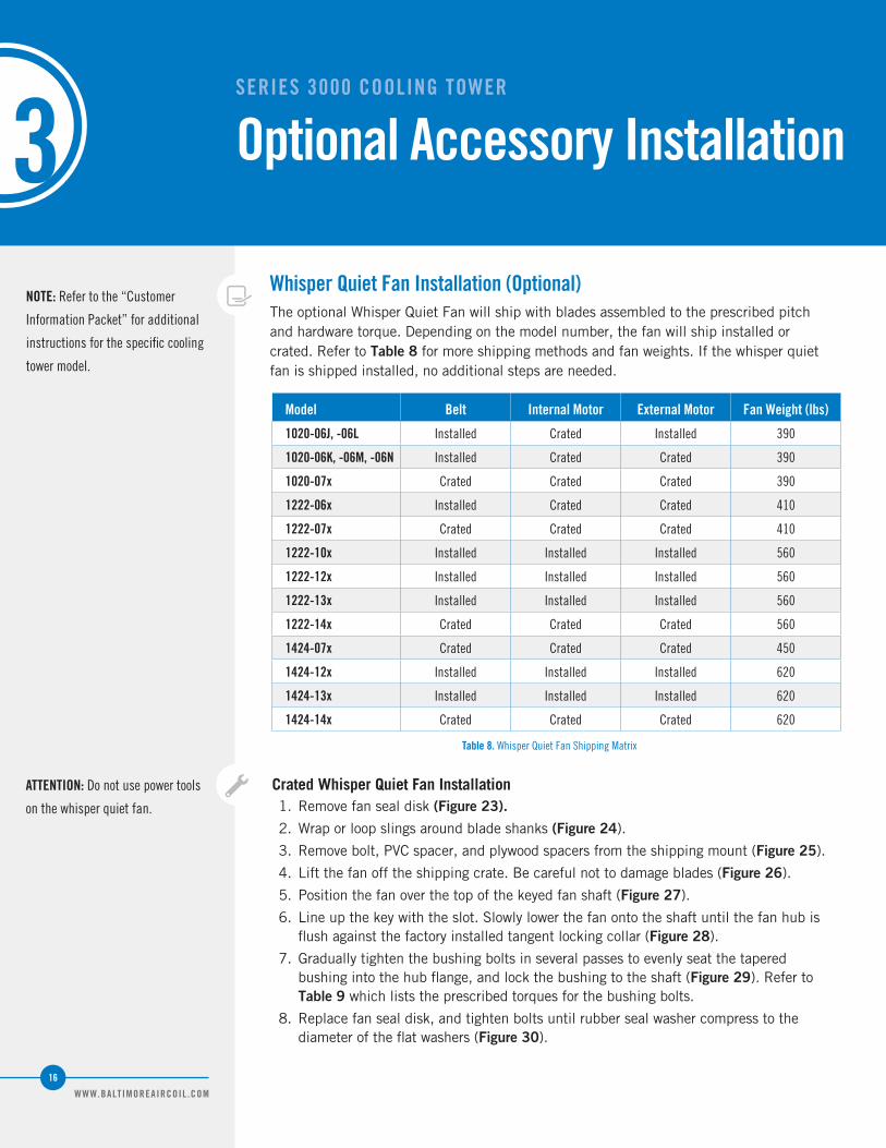
Whisper Quiet Fan Installation (Optional)The optional Whisper Quiet Fan will ship with blades assembled to the prescribed pitch and hardware torque. Depending on the model number, the fan will ship installed or crated. Refer to Table 8 for more shipping methods and fan weights. If the whisper quiet fan is shipped installed, no additional steps are needed.
Table 8. Whisper Quiet Fan Shipping Matrix
NOTE: Refer to the “Customer
Information Packet” for additional
instructions for the specific cooling
tower model.
Crated Whisper Quiet Fan Installation1. Remove fan seal disk (Figure 23).
2. Wrap or loop slings around blade shanks (Figure 24).
3. Remove bolt, PVC spacer, and plywood spacers from the shipping mount (Figure 25).
4. Lift the fan off the shipping crate. Be careful not to damage blades (Figure 26).
5. Position the fan over the top of the keyed fan shaft (Figure 27).
6. Line up the key with the slot. Slowly lower the fan onto the shaft until the fan hub is flush against the factory installed tangent locking collar (Figure 28).
7. Gradually tighten the bushing bolts in several passes to evenly seat the tapered bushing into the hub flange, and lock the bushing to the shaft (Figure 29). Refer to Table 9 which lists the prescribed torques for the bushing bolts.
8. Replace fan seal disk, and tighten bolts until rubber seal washer compress to the diameter of the flat washers (Figure 30).
SERIES 3000 COOLING TOWER
Optional Accessory Installation3
Model Belt Internal Motor External Motor Fan Weight (lbs)
1020-06J, -06L Installed Crated Installed 390
1020-06K, -06M, -06N Installed Crated Crated 390
1020-07x Crated Crated Crated 390
1222-06x Installed Crated Crated 410
1222-07x Crated Crated Crated 410
1222-10x Installed Installed Installed 560
1222-12x Installed Installed Installed 560
1222-13x Installed Installed Installed 560
1222-14x Crated Crated Crated 560
1424-07x Crated Crated Crated 450
1424-12x Installed Installed Installed 620
1424-13x Installed Installed Installed 620
1424-14x Crated Crated Crated 620
ATTENTION: Do not use power tools
on the whisper quiet fan.

WWW.BALTIMOREAIRCOIL .COM
17
Optional Accessory Installation
Whisper Quiet Fan Installation
Model Belt Internal Motor External Motor Fan Weight (lbs)
1020-06J, -06L Installed Crated Installed 390
1020-06K, -06M, -06N Installed Crated Crated 390
1020-07x Crated Crated Crated 390
1222-06x Installed Crated Crated 410
1222-07x Crated Crated Crated 410
1222-10x Installed Installed Installed 560
1222-12x Installed Installed Installed 560
1222-13x Installed Installed Installed 560
1222-14x Crated Crated Crated 560
1424-07x Crated Crated Crated 450
1424-12x Installed Installed Installed 620
1424-13x Installed Installed Installed 620
1424-14x Crated Crated Crated 620
FLAT WASHER
FLAT WASHER
SEAL WASHER
SEAL WASHER FAN SEAL DISK
Figure 23. Remove Seal Disk Figure 24. Attached to Blade Shanks
Figure 25. Remove Shipping Restraint Hardware Figure 26. Lift Fan From Crate
Model Number Bushing Type Bushing O.D. Hex Key Size Torque
1020-x U 4” 10mm 50 Ft-Lb
1222-x, 1424-x W 5.5” 14mm 90 Ft-Lb
Table 9. Bushing Torque
Figure 28. Key LineupFigure 27. Fan Positioning
Figure 30. Replace Seal DiskFigure 29. Bushing Bolts
Seal Disk
Remove Nut

WWW.BALTIMOREAIRCOIL .COM
18
Side Outlet Depressed Sump Box Installation (Optional)The optional side outlet depressed sump box allows a cooling tower water outlet connection to be piped from underneath the unit in four possible directions, 90° apart. The piping connection is a bolt circle designed to fit an ASME Class 150 flat face flange with a full-face gasket.
To install the side outlet depressed sump box, follow the steps below:
1. Wipe the edges around the opening inside the cold water basin to remove any dirt or moisture that may have accumulated during shipment.
2. Apply a layer of trapezoidal butyl sealer tape (BAC part #554009) around the opening in the basin over the centerline of the holes. Do not stretch the sealer tape too thinly or overlap at the corners. When it is necessary to splice the sealer tape, be sure to press the two ends together to form a smooth continuous strip. Apply a second layer of trapezoidal butyl sealer tape (BAC part #554009) over the first layer following the same procedure. Refer to Figure 29. The sealer tape needs to be positioned between the sump box and the inside basin bottom centered over the bolt holes.
3. Insert the sump box assembly into the opening in the cold water basin and attach it to the basin with 3/8” x 1” bolts, flat washers, lock washers, and nuts as shown in Figure 29, Detail A.
4. Place the suction strainer over the opening.
Figure 29. Side Outlet Depressed Sump Box Installation
Sump SuctionStrainer
Side OutletDepressedSump Box
Cold Water Basin
2 Layersof Trapezoidal
Butyl Sealer Tape
3/8" X 1" Bolt& Flatwasher
2 Layers ofTrapazoidal Butyl Sealer Tape
Lockwasher& 3/8" Nut
Detail A

WWW.BALTIMOREAIRCOIL .COM
19
Factory Pre-Wired Terminal Box (Optional)BAC offers an optional terminal box with factory pre-wiring for Series 3000 Cooling Towers. When this option is ordered, the cooling tower’s fan motor(s) and vibration cutout switch are wired at the factory (through flexible conduit and the mechanical equipment support) and terminated on the outside face of the BAC unit in a clearly marked, 304 Stainless Steel, NEMA 3R terminal box (see Figure 30 for the exterior location of the box on the cooling tower).
The box includes a cover plate, which once removed reveals an easy-to-follow wiring diagram and modular terminal blocks. Remove the cover plate, and install the collar (ships loose in the cooling tower’s basin) which has prepunched conduit holes. Wiring from the terminal blocks to the unit controls is sized, provided and installed by others. After the controls are wired, reinstall the cover plate on the terminal box.
A.B.C. Terminal Box/Pre-Wiring
(Factory Mounted)Some field installation andwiring required.
Access Door
Figure 30. Factory Pre-Wired Terminal Box Location
Optional Accessory Installation
Side Outlet Depressed Sump Box
Factory Pre-Wired Terminal Box
Additional Optional Accessories and Equipment
Additional Optional Accessories and EquipmentAll platforms, ladders, safety cages, and VR stacks will be factory assembled and will ship pre-assembled for field installation. These pre-assembled options should be installed on the cooling tower as shown on the appropriate reference drawing in the “Customer Information Packet.” Installation for additional optional accessories should also be installed as shown on the appropriate reference drawing in the “Customer Information Packet.” This packet will be in an envelope attached to the side of the unit or located in a box inside the unit.
COOLING TOWERS
CLOSED CIRCUIT COOLING TOWERS
ICE THERMAL STORAGE
EVAPORATIVE CONDENSERS
HYBRID PRODUCTS
PARTS & SERVICES
w w w . B a l t i m o r e A i r c o i l . c o m
7600 Dorsey Run Road, Jessup, MD 20794 › Telephone: (410) 799-6200 › Fax: (410) 799-6416
© 2014 Baltimore Aircoil Company › R-244/5-A-XE