Embed Size (px)
Citation preview

Installation and Operating Manual
Series 3 Liquid Level Switches
ASME B31.1 Construction

Read this Manual Before Installing
This manual provides information on Series 3 LiquidLevel Switches. It is important that all instructions are readcarefully and followed in sequence. Detailed instructionsare included in the Installation section of this manual.
Conventions Used in this Manual
Certain conventions are used in this manual to conveyspecific types of information. General technical material,support data, and safety information are presented innarrative form. The following styles are used for notes,cautions, and warnings.
Notes
Notes contain information that augments or clarifiesan operating step. Notes do not normally containactions. They follow the procedural steps to whichthey refer.
Cautions
Cautions alert the technician to special conditions thatcould injure personnel, damage equipment, or reducea component’s mechanical integrity. Cautions are alsoused to alert the technician to unsafe practices or theneed for special protective equipment or specificmaterials. In this manual, a caution box indicates apotentially hazardous situation which, if not avoided,may result in minor or moderate injury.
Warnings
Warnings identify potentially dangerous situations orserious hazards. In this manual, a warning indicates animminently hazardous situation which, if not avoided,could result in serious injury or death.
Safety Messages
Follow all standard industry procedures for servicing elec-trical equipment when working with or around highvoltage. Always shut off the power supply before touchingany components.
Low Voltage Directive
For use in Installation Category II, Pollution Degree 2. Ifequipment is used in a manner not specified by the manufacturer, protection provided by the equipment maybe impaired.
Notice of Trademark, Copyright, and LimitationsMagnetrol® & MAGNETROL logotype are registeredtrademarks of MAGNETROL International, Incorporated.
Copyright © 2016 MAGNETROL International.All rights reserved.
Performance specifications are effective with date of issueand are subject to change without notice. MAGNETROL reserves the right to make changes to theproduct described in this manual at any time withoutnotice. MAGNETROL makes no warranty with respectto the accuracy of the information in this manual.
Warranty
All MAGNETROL mechanical level and flow controlsare warranted free of defects in materials or workmanshipfor five full years from the date of original factory ship-ment. Repair parts are warranted free of defects in mate-rials and workmanship for one year from the date of ship-ment. Materials, specifications, and contents are subjectto change without prior written notice.
If returned within the warranty period; and, upon factoryinspection of the control, the cause of the claim isdetermined to be covered under the warranty; then,MAGNETROL will repair or replace the control at nocost to the purchaser (or owner) other than transportation.
MAGNETROL shall not be liable for misapplication,labor claims, direct or consequential damage or expensearising from the installation or use of equipment.There are no other warranties expressed or implied,except special written warranties covering some MAGNETROL products.
Quality Assurance
The quality assurance system in place at MAGNETROLguarantees the highest level of quality throughout thecompany. MAGNETROL is committed to providing fullcustomer satisfaction both in quality products and quali-ty service.
MAGNETROL’s quality assurance system isregistered to ISO 9001 affirming its com-mitment to known international qualitystandards providing the strongest assuranceof product/service quality available.
46-624 Series 3 Liquid Level Switches ASME B31.1 Construction
Table of Contents
1.0 Introduction1.1 Principle of Operation ..............................................41.2 Operating Cycle ........................................................4
2.0 Installation2.1 Unpacking ................................................................42.2 Critical Alarm Function ............................................52.3 Piping .......................................................................52.4 Mounting..................................................................52.5 Wiring ......................................................................6
3.0 Switch Differential Adjustment3.1 Low Level Controls ...................................................83.2 High Level Controls..................................................9
4.0 Preventive Maintenance4.1 Recommended Practice ...........................................10
4.1.1 Keep Control Clean .....................................104.1.2 Inspect Switch Mechanisms, Terminals,
and Connections Monthly ...........................104.1.3 Proof Test Procedure.....................................114.1.4 Control Head Removal and Installation .......12
4.2 Troubleshooting ......................................................144.2.1 Check Switch Mechanism ............................144.2.2 Check Sensing Unit......................................15
4.3 What To Avoid........................................................16
5.0 Reference Information5.1 Agency Approvals....................................................175.2 Specifications ..........................................................18
5.2.1 Dimensional Data — Sealed Cage Models....185.2.2 Dimensional Specifications — Sealed
Cage Models ................................................195.2.3 Dimensional Data —Flanged Cage Models ...215.2.4 Dimensional Specifications — Flanged
Cage Models ................................................225.2.4.1 150# & 300# ANSI Pressure Ratings......225.2.4.2 600# & 900# ANSI Pressure Ratings......23
5.2.5 Actuating Levels, Steam Service Ratingsand Specific Gravities ...................................24
5.3 Replacement Parts ...................................................255.3.1 Sealed Cage Float Models B35, C35, G35,
V35 and Z35 Parts Identification.................255.3.2 Sealed Cage Float Models B35, C35, G35,
V35 and Z35 Part Numbers.........................255.3.3 Flanged Cage Float Models B3F, G3F, K3F
and Z3F Parts Identification ........................265.3.4 Flanged Cage Float Models B3F, G3F, K3F
and Z3F Part Numbers ................................275.4 Model Numbers ......................................................28
5.4.1 Sealed Cage Models......................................285.4.2 Flanged Cage Models ...................................30
Series 3Liquid Level Switches
ASME B31.1 Construction

4 46-624 Series 3 Liquid Level Switches ASME B31.1 Construction
Swing inposition
Switch
Return spring
Enclosing tube(non-magnetic)
Attractionsleeve
Magnet
HL
1.0 Introduction
The MAGNETROL Series 3 level switches are float oper-ated units suitable for use on clean liquid applications forlevel alarm, pump control and safety shutdown functions.Units are designed, fabricated and certified to compliancewith ASME B31.1 specifications.
1.1 Principle of Operation
The design of MAGNETROL float-operated level switchesis based upon the principle that a magnetic field will pene-trate non-magnetic materials such as 316 stainless steel.The float moves a magnetic attraction sleeve within a non-magnetic enclosing tube and actuates a switch mechanism.The enclosing tube provides a pressure seal to the chamberand therefore to the process.
1.2 Operating Cycle
As the liquid level rises in the chamber (refer to Figure 1),the float moves the magnetic attraction sleeve up withinthe enclosing tube and into the field of the switch mecha-nism magnet. As a result, the magnet is drawn in tightlyto the enclosing tube causing the switch to trip, “making”or “breaking” an electrical circuit. As the liquid level falls,the float drops and moves the attraction sleeve out of themagnetic field, releasing the switch at a predetermined“low level” (refer to Figure 2). The tension spring ensuresthe return of the switch in a snap action.
2.0 Installation
2.1 Unpacking
Unpack the instrument carefully. Inspect all units fordamage. Report any concealed damage to carrier within24 hours. Check the contents of the packing slip and purchase order. Check and record the serial numbers andmodel numbers for future reference when ordering parts.
Serial # _____________________________________
Model # _____________________________________
Figure 1
Switch Tripped
Swing outposition
LL
Figure 2
Switch Released

46-624 Series 3 Liquid Level Switches ASME B31.1 Construction 5
2.2 Critical Alarm Function
It is recommended that for critical alarm functions, anadditional level switch be installed as a high–high or low–low level alarm for maximum protection.
2.3 Piping
Figure 3 shows a typical piping installation of a MAGNETROL Series 3 control to a pressure vessel. Leveldecals on control identify the actuation levels for the bot-tom switch mechanism of a unit with three switches atminimum specific gravity. To find the actuation levels for aunit with one switch at different minimum specific gravi-ties, refer to the charts in Actuation Levels, Steam ServiceRatings and Specific Gravities, Section 5.2.5, on page 24.
Use pipe of sufficient strength to support the control. Ifnecessary, provide a stand or hanger to help support itsweight. All piping should be straight and free of “lowspots” or “pockets” so that lower liquid line will draintowards the vessel and upper vapor line will drain towardthe control. Shut-off valves are recommended for installa-tion between the vessel and the control. If control is to beused with a low temperature liquid (one which will “boil”in the float chamber if outside heat is absorbed), thechamber and piping should be insulated. Such boilingin the chamber will cause false level indications.DO NOT INSULATE SWITCH MECHANISMHOUSING.
On controls equipped with pneumatic switch assemblies,consult bulletin on mechanism furnished for air (or gas)piping instructions. Refer to the chart on page 7 forbulletin numbers for pneumatic switches.
2.4 Mounting
Caution: If equipment is used in a manner not specified by themanufacturer, protection provided by the equipment maybe impaired.
Caution: This instrument is intended for use in Installation CategoryII, Pollution Degree 2.
Adjust piping as required to bring control to a verticalposition. MAGNETROL controls must be mounted with-in 3° of vertical. A 3° slant is noticeable by eye, but instal-lation should be checked with a spirit level on top and/orsides of float chamber.
Shutoffvalve
Drainvalve
Conduitoutlet
Switchactuating
levelreference
marks
Max. 12"
Pressurevessel
Figure 3
Typical Piping Arrangement

6 46-624 Series 3 Liquid Level Switches ASME B31.1 Construction
Controls should be mounted as close to the vessel as possi-ble. This will result in a more responsive and accurate levelchange in the control. Liquid in a long line may be coolerand more dense than liquid in the vessel causing lower levelindication in the control than actual level in the vessel.
Caution: Operation of all buoyancy type level devices should bedone in such a way as to minimize the action of dynamicforces on the float or displacer sensing element. Goodpractice for reducing the likelihood of damage to the con-trol is to equalize pressure across the device slowly.
2.5 Wiring
NOTE: A switch or circuit breaker shall be installed in close proximi-ty to equipment and within easy reach of operator. It shall bemarked as the disconnecting device for the equipment.
NOTE: For supply connections in installations with ambient tempera-ture up to +158 °F (+70 °C), use wire with a minimum rating of +167 °F (+75 °C) as required by the process conditions. Installations with ambient temperatures up to +176 °F (+80 °C)require wire with a minimum rating of +185 °F (+85 °C) asrequired by the process conditions. Use a minimum of 14AWG wire for power and ground field wires.
Caution: Level controls are shipped from the factory with theenclosing tube tightened and the middle set screw, on thehousing base, locked to the enclosing tube. Failure toloosen the set screw prior to repositioning the conduit con-nection may cause the enclosing tube to loosen, resultingin the possible leakage of the process liquid or vapor.
Series 3 controls are shipped with the conduit entry ofthe switch housing placed 180° opposite to the tank con-figurations to simplify installation in most cases. If thisconfiguration is appropriate to the installation, proceed tostep 4 to begin wiring the unit. If another configuration isdesired, the switch housing can be easily rotated by firstfollowing steps 1, 2, and 3.
1. Loosen set screw(s) at base of switch housing. Refer toFigure 4.
2. Switch housing may be rotated 360° to allow correct posi-tioning of conduit outlet.
3. Tighten set screw(s) at base of switch housing.
4. Unscrew and remove switch housing cover. The threadshave been lubricated to facilitate removal.
NOTE: On high temperature applications (above +250 °F [+121 °C] infloat chamber), high temperature wire should be usedbetween control and first junction box located in a coolerarea. On non-hazardous applications, flexible conduit may beused between the control and the first junction box.
Internal Circuit(Right) Switch1
2
3
Load
Load
Close on high level
Common
Close on low level
Line
4
5
6
Internal Circuit(Left) Switch
Load
Load
Close on high level
Common
Close on low level
Line
SetScrew
ScrewScrew
Figure 4
NEMA 4X/7/9
Figure 5
Wiring diagram for DPDT
Series A, B, C, D, E & F switches

46-624 Series 3 Liquid Level Switches ASME B31.1 Construction 7
5. The switch terminals are located next to the conduit outletto facilitate wiring. Bring supply wires through conduitoutlet. Route extra wire around enclosing tube under thebaffle plate and connect them to the proper terminals.Refer to the wiring diagram in your switch bulletin for thisinformation. Refer to chart below for switch instructionmanual numbers.
NOTE: For models with a Series HS switch with high temperaturelead wire, the leads are routed out through the conduit open-ing by the factory. A suitable conduit box should be providedfor the connection of the leads to the control wiring.
6. Dress wiring to ensure no interference or contact withactuation of switch, or replacement of switch housingcover.
OBSERVE ALL APPLICABLE ELECTRICAL CODESAND PROPER WIRING PROCEDURES.
Prevent moisture seepage into the enclosure by installingapproved seal-drain fittings in the conduit run leading intothe unit.
Caution: In hazardous areas, do not power the unit until the conduit is sealed and the enclosure cover is screweddown securely.
7. Replace housing cover.
8. If control has been furnished with an explosion proof ormoisture proof (gasketed) switch housing, it must besealed at the conduit outlet with a suitable compound ornon-hardening sealant to prevent entrance of air.
9. Test switch action by varying liquid level in float chamber.
NOTE: If switch mechanism fails to function properly, check verticalalignment of control housing and consult installation bulletinon switch mechanism furnished.
10. Check cover-to-base fit to be certain that gasketed joint istight. A positive seal is necessary to prevent infiltration ofmoisture-laden air or corrosive gasses into switch housings.
Switch SeriesDescription
BulletinLetter No.
B, C, D Dry Contact Switch 42-683
F, 8, 9 High Temperature Hermetically SealedSnap Switch 42-799
HS Hermetically Sealed Snap Switch 42-694
R High Temperature Snap Switch 42-799
J Bleed Type Pneumatic Switch 42-685
K Non-Bleed Type Pneumatic Switch 42-686

8 46-624 Series 3 Liquid Level Switches ASME B31.1 Construction
3.0 Switch Differential Adjustment
The standard differential of Series 3 float models with onlyone switch mechanism may be field-adjusted. Adjustmentmay be necessary if a wider differential needs to be set toovercome switch chatter caused by the process.
The differential, or the amount of level travel between“switch-on” and “switch-off ”, may be adjusted byrepositioning the lower jam nuts on the float stem.This adjustment is different for high level and low levelcontrols. Refer to the appropriate section below foradjustment instructions.
Caution: Maximum differential adjustment is 1 inch (25 mm).
3.1 Low Level Controls
On low level controls the switch trips on the lower actuationpoint and resets on the higher actuation point. Wideningthe differential will allow the switch to trip on the originalactuation point and reset at a later, or higher, point.
The differential on low level controls may be adjusted byrepositioning the lower jam nuts on the float stem. Thestandard factory setting is for a minimum amount of play(gap) between the top jam nuts and the attraction sleeve asshown in Figure 7 on page 9.
1. Determine what change in differential is necessary.
NOTE: To widen the differential one inch, the lower jam nuts must beset proportionately lower on the stem (i.e., in this example 1 inch).
2. Make sure power source is turned off.
3. NEMA 4X/7/9—Unscrew and remove switch housingcover.
4. Disconnect power supply wires from switch mechanism.Pull wires out of conduit connection opening in housingbase. Refer to Figure 6.
5a. Perform system shut-down procedures as required torelieve pressure from float chamber of control. Allow unitto cool.
5b. Close shut-off valves (if so equipped) to isolate controlfrom tank. Drain off liquid in float chamber. Refer toFigure 3 on page 5.
5c. On installations without shut-off valves, relieve pressurefrom the tank. Drain liquid in tank to a level below theconnections of the float chamber.
Float
Enclosing tube
Refer to Figures 7 and 8
Housing base
Enclosing tube nut
Conduitconnection
Switch housing cover
Chamber
Figure 6

46-624 Series 3 Liquid Level Switches ASME B31.1 Construction 9
NOTE: Level control, connections and pipe lines need not beremoved from the tank.
6. Loosen enclosing tube nut with a 15⁄16" wrench. Unscrewenclosing tube counterclockwise (switch and housing basewill rotate also) until it is free. Refer to Figure 6 on page 8.
7. Lift enclosing tube, switch, and base off float chamber.Jam nuts and attraction sleeve are now accessible.
8. Measure the distance “D” from the top edge of the upperjam nuts to the top of the float stem. Refer to Figure 8.Record this measurement.
9. Loosen and remove upper jam nuts, guide washer, andattraction sleeve.
10. Loosen and adjust lower jam nuts to the desired position.Tighten lower jam nuts securely. Refer to Figure 8.
11. Replace attraction sleeve on stem.
12. Replace upper jam nuts and guide washer on the stem inthe position previously noted. Tighten upper jam nutssecurely. Refer to Figure 8.
NOTE: Using a new enclosing tube gasket when reassemblingenclosing tube to the chamber. Make certain that all gasketsurfaces are thoroughly cleaned to allow proper gasket seating. Coat enclosing tube threads with “anti-seizing” compound.
13. Replace enclosing tube, switch, and base on chamber. Screwtube clockwise until tightened to 200–225 foot-poundsof torque.
14. Rotate switch housing to correct position and tighten setscrew at base of switch housing. Refer to Figure 4 onpage 6.
15. Bring supply wires through conduit outlet. Follow steps 5through 10 inWiring, Section 2.5 on pages 6 and 7.
16. Test switch action by varying liquid level in float chamber.
NOTE: If switch mechanism fails to function properly, check verticalalignment of control housing and consult installation bulletinon switch mechanism. If the unit still fails to function properly, consult the factory.
3.2 High Level Controls
On high level controls the switch trips on the higher actu-ation point and resets on the lower actuation point.
Caution: On high level controls, widening the differential requiresraising the trip point a proportional amount. The resetpoint will remain the same.
Slightplay (gap)
Must beallowed
(0.03"typical)
Position ofbottom
jam nuts(normalfactorysetting)
Replace in same position
Maximum gapsetting (applies tomodels having a
single switchmechanism witha single magnetactuator only)
1.00(25 mm)
Drop bottomjam nuts toincrease gapsetting (referto aboveinstructions)
Figure 7 Figure 8
D

10 46-624 Series 3 Liquid Level Switches ASME B31.1 Construction
To widen the differential by raising the trip point, followsteps 1 through 16 in Low Level Controls, Section 3.1,pages 8–9).
Caution: After increasing gap setting, be certain to check for proper operation of switch mechanism by raising and low-ering float assembly. Magnet must “snap” cleanly withadditional float movement available after magnet snaps.
4.0 Preventive Maintenance
Periodic inspections are a necessary means to keep yourlevel control in good working order. This control is a safetydevice to protect the valuable equipment it serves. A sys-tematic program of “preventive maintenance” must beimplemented when the control is placed into service. If thefollowing sections on “what to do” and “what to avoid” areobserved, your control will provide reliable protection ofyour equipment for many years.
4.1 Recommended Practice
4.1.1 Keep Control Clean
Be sure the switch housing cover is always in place on thecontrol. This cover is designed to keep dust and dirt frominterfering with switch mechanism operation. In addition,it protects against damaging moisture and acts as a safetyfeature by keeping bare wires and terminals from beingexposed. Should the housing cover or any seals becomedamaged or misplaced, obtain a replacement immediately.
4.1.2 Inspect Switch Mechanisms, Terminals, andConnections Monthly
1. Dry contact switches should be inspected for excessivewear on actuating lever or misalignment of adjustmentscrew at point of contact between screw and lever. Suchwear can cause false switch actuating levels. See switchmechanism bulletin supplied with control should switchadjustment or replacement be necessary.
2. DO NOT operate your control with defective or mal-adjusted switch mechanisms. Refer to the SwitchInstruction Reference Bulletins chart on page 7 to findappropriate bulletins for service instructions.
3. Level controls may sometimes be exposed to excessiveheat or moisture. Under such conditions, insulation onelectrical wiring may become brittle, eventually breakingor peeling away. The resulting “bare” wires can causefalse trip.

46-624 Series 3 Liquid Level Switches ASME B31.1 Construction 11
4. Vibration may sometimes cause terminal screws to loosen.Check all terminal connections to be certain that screwsare tight.
5. On units with pneumatic switches, air (or gas) linessubjected to vibration, may eventually crack or loosen atconnections causing leakage. Check lines and connectionscarefully and repair or replace, if necessary.
NOTE: Spare switches should be kept on hand at all times.
4.1.3 Proof Test Procedure(To be performed annually at a minimum)
1. Bypass the logic controller or take other action to avoid afalse trip.
2. Perform a detailed inspection of the unit inside and outfor physical damage that may impact the structural integrity, and for evidence of environmental or processleaks. Repair or replace the unit if needed.
3. Using a calibrated multimeter set to measure electricalresistance (ohms), at the field connections measure andrecord the resistances across the Common (C) and theNormally Closed (NC) contacts, and the Common (C)and the Normally Open (NO) contacts.
4. Change the process level to cause the switch mechanism tochange states.
5. Again, measure and record the resistances across theCommon (C) and the Normally Closed (NC) contacts,and the Common (C) and the Normally Open (NO) contacts.
6. Ensure with the multimeter readings that the switch mech-anism did in-fact change states. A closed switch contactshould measure less than 1 ohm, and an open contactshould measure greater than 5 megaohms.
7. Repeat steps 3 through 6 for all other sets of switch contacts (if any).
8. Restore the installation to normal operation.

12 46-624 Series 3 Liquid Level Switches ASME B31.1 Construction
4.1.4 Control Head Removal and Installation
Inspection of the interior of the chamber is possible onflanged cage models. To do this, the control head must beremoved to provide proper access to the chamber. Thisprocedure will assure that the head assembly is removedand reinstalled properly.
1. Allow vessel to get to safe temperature and pressure beforeopening the pressure boundary.
2. Power down all wiring to the unit.
3. Remove all wiring and conduit from the unit.
4. Remove flange bolts.
5. Prepare an area where the head assembly can be placedsuch that it rests on the flange in its normal orientation(two 2×4 boards placed across an open drum work well).Refer to Figure 9.
6. Carefully lift the head assembly by holding the sides of theflange. Maintain the head assembly as much as possible inthe vertical position.
NOTE: Care must be taken not to place side force on the float whichcould bend the stem.
7. With the unit resting in its temporary fixture in an uprightposition, it can now be inspected or repaired.
Caution: Do not place the unit on its side — this could result indamage to the stem.
Figure 9
Control Head Removal Control Head Installation

46-624 Series 3 Liquid Level Switches ASME B31.1 Construction 13
8. Conduct a check for float stem straightness as follows:
8.1 Remove the stem assembly including attraction sleevefrom the head assembly by removing the two screwsholding the stop strap to the bottom of the flange.See Figure 10 for assembly schematic.
8.2 Check the stem straightness by aligning the stemagainst a straight edge. Stems that are bent in excess of1⁄8 inch over any 6 inch length should not be usedin this condition. Replace any bent stems. SeeReplacement Parts, Section 5.3 beginning on page 25.
8.3 Ensure that the components in the stem assembly arein good condition and surfaces are clear of potentialobstructions. The stem assembly is reinstalled bysecuring the stop strap to the flange. Ensure that theattraction sleeve moves freely through the enclosingtube and that the stem assembly surfaces are smooth.
NOTE: Care must be taken during the straightness check to be cer-tain that the attraction sleeve is not removed from the stemand jam nuts settings are not changed.
9. In the container that the unit is set on, raise the liquidlevel sufficiently to lift the float and trip the switch mecha-nism. Inspect inside of chamber for any obstructions orscale buildup. If excessive buildup is present, the intervalbetween inspections should be shortened. Remove old gas-ket such that mating flange surfaces are completely clean.Position new gasket on chamber flange before replacingthe head assembly.
NOTE: The float is restricted from moving laterally by the chamber, inthe test configuration the float and stem can move further offcenter than possible under normal operation. Avoid excessmovement in this lateral direction during the test. If switchtrips, the unit may be reassembled.
10. Replace the assembly onto the float cage keeping it as vertical as possible. Carefully lower the assembly into thechamber making sure that the stem does not become bentduring installation. Refer to Figure 9 on page 12.
11. Tighten flange bolts per torque values as indicated in table below.
12. Attach wiring and connect power supply as described inWiring, Section 2.5 on page 6.
Model Flange Bolting Enclosing Tube
B3F – 150# 100 – 120 ft-lbs
200–225 ft-lbs
B3F – 300#, G3F – 150#, G3F – 300# 180 – 200 ft-lbs
B3F – 600# 300 – 320 ft-lbs
G3F – 600#, Z3F – 600# 470 – 490 ft-lbs
K3F – 600# 675 – 710 ft-lbs
Z3F – 900# 775 – 850 ft-lbs
0.03"Minimum
gap setting
Top jam nutsBottom jamnuts
AttractionsleeveEnclosing tube(ref.)
Stop tube
Sleeve stop strapRetaining
screws
Float and stemassembly
Headflange(ref.)
Dim. A
Figure 10

14 46-624 Series 3 Liquid Level Switches ASME B31.1 Construction
4.2 Troubleshooting
Usually the first indication of improper operation is failureof the controlled equipment to function, i.e., pump willnot start (or stop), signal lamps fail to light, etc. Whenthese symptoms occur, whether at time of installation orduring routine service thereafter, check the followingpotential external causes first:
• Fuses may be blown
• Reset button(s) may need resetting
• Power switch may be open
• Controlled equipment may be faulty
• Wiring leading to control may be defective
If a thorough inspection of these possible conditions failsto locate the trouble, proceed next to a check of thecontrol's switch mechanism.
4.2.1 Check Switch Mechanism
1. Pull switch or otherwise disconnect power to the control.
2. Remove switch housing cover.
3. Disconnect power wiring from switch assembly.
4. Swing magnet assembly in and out by hand to check care-fully for any sign of binding. Assembly should requireminimal force to move it through its full swing.
5. If binding exists, magnet may be rubbing enclosing tube.If magnet is rubbing, loosen magnet clamp screw and shiftmagnet position. Retighten magnet clamp screw.
6. If switch magnet assembly swings freely and mechanismstill fails to actuate, check installation of control to becertain it is within the specified 3° of vertical.
7. Examine the switch closely as described in Inspect SwitchMechanisms, Terminals, and Connections Monthly, Section4.1.2, step 1 on page 10. Check continuity of switch withohmmeter. If switch does not function properly, replace itimmediately.
8. If switch mechanism is operating satisfactorily, proceed tocheck sensing unit.
NOTE: Spare switches should be kept on hand at all times.

46-624 Series 3 Liquid Level Switches ASME B31.1 Construction 15
4.2.2 Check Sensing Unit
1. Reconnect power supply. Carefully actuate the switchmechanism manually (use a non-conductive tool on elec-trical switch mechanisms) to determine whether controlledequipment will operate.
Caution: With electrical power on, avoid contact with switch leadsand connections at terminal block.
2. If controlled equipment responds to manual switch actua-tion test, trouble may be located in the level sensing por-tion of the control, float(s), stem(s), and magnetic attrac-tion sleeve(s).
3. Check to be certain liquid is entering float chamber.A valve may be closed or piping plugged.
Caution: Be certain to pull disconnect switch or otherwise ensurethat electrical circuit(s) through control is deactivated.Close operating medium supply valve on controlsequipped with pneumatic switch mechanisms.
4. Disconnect wiring from supply side of switch mechanism(s)and remove electrical conduit or operating medium lineconnections to switch housing.
5. Perform system shutdown to relieve pressure from floatchamber of control and allow unit to cool.
6. Close shutoff valves (if equipped) to isolate control fromvessel. Drain off liquid in chamber if necessary
7. On installations without shutoff valves, relieve pressurefrom vessel and drain off liquid head above controlmounting level.
NOTE: Control chamber, connections, and pipe lines need not beremoved from vessel or boiler.
8. Remove switch housing assembly by loosening enclosingtube hex nut, which is located immediately below housingbase. Refer to Figure 4 on 6.
9. With switch housing assembly removed, inspect attractionsleeve(s) and inside of enclosing tube for excessive corrosionor solids buildup, which could restrict movement, prevent-ing sleeve(s) from reaching field of switch magnet(s).
10. If differential has been changed in the field by reposition-ing the lower jam nuts on the float stem, check tightnessand position of the jam nuts.
11. Check float to be certain it is buoyant in the liquid (floatchamber or vessel must have adequate liquid level). If floatis determined to be filled with liquid, or it is collapsed, itmust be replaced immediately.
Optional blow-downor drain valve
Shutoff valve(if used)
Conduitoutlet
Switchactuating
level referencemark
Optional liquid legconnection to vessel
Shutoff valve(if used)
Figure 11

16 46-624 Series 3 Liquid Level Switches ASME B31.1 Construction
Caution: Do not attempt to repair a float. See Replacement Parts,Section 5.3 beginning on page 25.
If all components in the control are in operating condition,the trouble is likely located external to the control. Repeatinspection of external conditions previously described.
NOTE: If difficulties are encountered which cannot be identified, consult the factory or your local representative for assistance.A complete description of the trouble should be providedalong with information concerning your piping and mountingarrangement, plus a description of your operating sequence.Sketches or photographs showing the installation are alsobeneficial.
When communicating about your control, be certain toalways specify the complete Model and Serial numbers.
4.3 What To Avoid
1. Never leave switch housing cover off the control longerthan necessary to make routine inspections.
2. Never place a jumper wire across terminals to “cut-out”the control. If a “jumper” is necessary for test purposes, be certain it is removed before placing control into service.
3. Never attempt to make adjustments or replace switcheswithout reading instructions carefully. Certain adjustmentsprovided for in level controls should not be attempted inthe field. When in doubt, consult the factory or your localrepresentative.
4. Never use lubricants on pivots of switch mechanisms. A sufficient amount of lubricant has been applied at thefactory to ensure a lifetime of service. Further oiling isunnecessary and will only tend to attract dust and dirtwhich can interfere with mechanism operation.
Caution: Operation of all buoyancy type level devices should bedone in such a way as to minimize the action of dynamicforces on the float or displacer sensing element. Goodpractice for reducing the likelihood of damage to the control is to equalize pressure across the device veryslowly.

46-624 Series 3 Liquid Level Switches ASME B31.1 Construction 17
AgENCy APPROvED MODEL APPROvAL CLASSES
FM All with an electric switch mechanism and a housing Class I, Div 1, Groups C & Dlisted as NEMA 4X/7/9 Class II, Div 1, Groups E, F & G
All with an electric switch mechanism and a housing Class I, Div 1, Groups B, C & Dlisted as NEMA 4X/7/9 Class I, Div 1, Group B Class II, Div 1, Groups E, F & G
CSA All with a Series HS, F, 8 or 9 electric switch Class I, Div 2, Groups A, B, C & Dmechanism and a housing listed as CSA TYPE 4X
All with an electric switch mechanism and a housing Class I, Div 1, Groups C & Dlisted as NEMA 4X/7/9 Class II, Div 1, Groups E, F & G
All with an electric switch mechanism and a housing Class I, Div 1, Groups B, C & Dlisted as NEMA 4X/7/9 Class I, Div 1, Group B Class II, Div 1, Groups E, F & G
ATEX / IEC Ex ➁ All with an electric switch mechanism and an ATEX II 2 G EEx d IIC T6ATEX housing➀ 94/9/EC
IEC Ex Ex d IIC T6IP 66
CE All models Installation Category IIPollution Degree 2
Low Voltage Directives2006/95/ECper Harmonized StandardEN 61010-1/1993 & Amendment No. 1
5.0 Reference Information
5.1 Agency Approvals
➀ Controls with two or more HS switches are not ATEX approved.
➁ IEC Installation Instructions:
The cable entry and closing devices shall be Ex d certified suitable for the conditions of use and correctly installed.
For ambient temperatures above +55 °C or for process temperatures above +150 °C, suitable heat resistant cables shall beused.
Heat extensions (between process connection and housing) shall never be insulated.
Special conditions for safe use:
When the equipment is installed in process temperatures higher than +85 °C the temperature classification must be reducedaccording to the following table as per IEC60079-0.
Maximum Process
Temperature
Temperature
Classification
< 85 °C T6
< 100 °C T5
< 135 °C T4
< 200 °C T3
< 300 °C T2
< 450 °C T1
These units are in conformity with IECEx KEM 05.0020XClassification Ex d IIC T6Tambient -40 °C to +70 °C

18 46-624 Series 3 Liquid Level Switches ASME B31.1 Construction
5.2 Specifications
5.2.1 Dimensional Data — Sealed Cage Models
K
M
PluggedK
L
HLLL
G
J(Ref)
H
K
M
PluggedK
L
HLLL
D
E
F(Ref)
NEMA 1: 8.50 (216)NEMA 4X/7/9: 10.12 (257)Group B: 10.12 (257)
C
B
(Ref)
K
HLLL
A
K
M
Plugged
L
Figure 14
Flanged Side/Side
Figure 13
Flanged Upper Side/Bottom
Figure 12
Threaded & Socket Weld
Upper Side/Bottom
Conduit Connections K
Actuation levels
Allow 8" (203 mm) over headclearance for cover removal.
All housings rotatable 360°.
Electrical SwitchesNEMA 4X/7/9: 1" NPTGroup B: 1" NPT
Pneumatic SwitchesNEMA 1: 1⁄4" NPT
Outline Dimensions
L M
NEMA 4X/7/9 3.87 5.93NEMA 4X/7/9, (98) (151)Group B
NEMA 15.00 4.62(127) (117)
Inches (mm)

46-624 Series 3 Liquid Level Switches ASME B31.1 Construction 19
5.2.2 Dimensional Specifications – Sealed Cage Models
CHAMBERS WITH 1-INCH CONNECTIONS — 150 LB. AND 300 LB. ANSI CLASS
CHAMBERS WITH 11⁄2-INCH CONNECTIONS — 150 LB. AND 300 LB. ANSI CLASS
CHAMBERS WITH 2-INCH CONNECTIONS — 150 LB. AND 300 LB. ANSI CLASS
ModelCode
1" NPT Threaded& Socket Weld
1" FlangedUpper Side/Bottom
1" FlangedSide/Side
A B CD
EF g
HJ
Std. 14" Std. 14" Std. 14" Std. 14"
B35 8.92(227)
4.15(105)
15.12(384)
11.56(294)
14.00(356)
6.69(170)
17.76(451)
20.20(513)
12.21(310)
14.00(356)
6.69(170)
18.41(468)
20.20(513)
C35 8.92(227)
4.15(105)
15.12(384)
11.56(294)
14.00(356)
6.69(170)
17.76(451)
20.20(513)
12.21(310)
14.00(356)
6.69(170)
18.41(468)
20.20(513)
G35 9.80(249)
4.69(119)
16.17(410)
12.31(313)
14.00(356)
7.19(183)
18.68(474)
20.36(517)
12.96(329)
14.00(356)
7.19(183)
19.33(490)
20.36(517)
V35 8.92(227)
4.15(105)
15.12(384)
11.56(294)
14.00(356)
6.69(170)
17.76(451)
20.20(513)
12.21(310)
14.00(356)
6.69(170)
18.41(468)
20.20(513)
Z35 9.80(249)
4.69(119)
16.17(410)
12.31(313)
14.00(356)
7.19(183)
18.68(474)
20.36(517)
12.96(329)
14.00(356)
7.19(183)
19.33(490)
20.36(517)
ModelCode
11⁄2" NPT Threaded& Socket Weld
11⁄2" FlangedUpper Side/Bottom
11⁄2" FlangedSide/Side
A B CD
EF g
HJ
Std. 14" Std. 14" Std. 14" Std. 14"
B35 8.92(227)
4.22(107)
15.12(384)
12.56(319)
14.00(356)
7.69(195)
18.76(477)
20.20(513)
13.21(336)
14.00(356)
7.69(195)
19.41(493)
20.20(513)
C35 8.92(227)
4.22(107)
15.12(384)
12.56(319)
14.00(356)
7.69(195)
18.76(477)
20.20(513)
13.21(336)
14.00(356)
7.69(195)
19.41(493)
20.20(513)
G35 9.80(249)
4.75(121)
16.17(410)
13.31(338)
14.00(356)
8.19(208)
19.68(500)
20.36(517)
13.96(355)
14.00(356)
8.19(208)
20.33(516)
20.36(517)
V35 8.92(227)
4.22(107)
15.12(384)
12.56(319)
14.00(356)
7.69(195)
18.76(477)
20.20(513)
13.21(336)
14.00(356)
7.69(195)
19.41(493)
20.20(513)
Z35 9.80(249)
4.75(121)
16.17(410)
13.31(338)
14.00(356)
8.19(208)
19.68(500)
20.36(517)
13.96(355)
14.00(356)
8.19(208)
20.33(516)
20.36(517)
ModelCode
2" NPT Threaded& Socket Weld
2" FlangedUpper Side/Bottom
2" FlangedSide/Side
A B CD
EF g
HJ
Std. 14" Std. 14" Std. 14" Std. 14"
B35 8.92(227)
4.34(110)
15.12(384)
12.56(319)
14.00(356)
7.69(195)
18.76(477)
20.20(513)
13.21(336)
14.00(356)
7.69(195)
19.41(493)
20.20(513)
C35 8.92(227)
4.34(110)
15.12(384)
12.56(319)
14.00(356)
7.69(195)
18.76(477)
20.20(513)
13.21(336)
14.00(356)
7.69(195)
19.41(493)
20.20(513)
G35 9.80(249)
4.88(124)
16.17(410)
13.31(338)
14.00(356)
8.19(208)
19.68(500)
20.36(517)
13.96(355)
14.00(356)
8.19(208)
20.33(516)
20.36(517)
V35 8.92(227)
4.34(110)
15.12(384)
12.56(319)
14.00(356)
7.69(195)
18.76(477)
20.20(513)
13.21(336)
14.00(356)
7.69(195)
19.41(493)
20.20(513)
Z35 9.80(249)
4.88(124)
16.17(410)
13.31(338)
14.00(356)
8.19(208)
19.68(500)
20.36(517)
13.96(355)
14.00(356)
8.19(208)
20.33(516)
20.36(517)
Inches (mm)

20 46-624 Series 3 Liquid Level Switches ASME B31.1 Construction
5.2.2 Dimensional Specifications – Sealed Cage Models (cont.)
CHAMBERS WITH 11⁄2-INCH CONNECTIONS — 600 LB. & 900 LB. ANSI CLASS
CHAMBERS WITH 2-INCH CONNECTIONS — 600 LB. & 900 LB. ANSI CLASS
ModelCode
11⁄2" NPT Threaded& Socket Weld
11⁄2" FlangedUpper Side/Bottom
11⁄2" FlangedSide/Side
A B CD
EF g
HJ
14" 16" 14" 16" 14" 16" 14" 16"
B35 8.92(227)
4.22(107)
15.12(384)
14.00(356) — 9.00
(229)20.20(513) — 14.00
(356) — 9.00(229)
20.20(513) —
C35 8.92(227)
4.22(107)
15.12(384)
14.00(356) — 9.00
(229)20.20(513) — 14.00
(356) — 9.00(229)
20.20(513) —
G35 9.80(249)
4.75(121)
16.17(410) — 16.00
(406)10.00(254) — 22.36
(568) — 16.00(406)
10.00(254) — 22.36
(568)
V35 8.92(227)
4.22(107)
15.12(384)
14.00(356) — 9.00
(229)20.20(513) — 14.00
(356) — 9.00(229)
20.20(513) —
Z35 9.80(249)
4.75(121)
16.17(410) — 16.00
(406)10.00(254) — 22.36
(568) — 16.00(406)
10.00(254) — 22.36
(568)
ModelCode
2" NPT Threaded& Socket Weld
2" FlangedUpper Side/Bottom
2" FlangedSide/Side
A B CD
EF g
HJ
14" 16" 14" 16" 14" 16" 14" 16"
B35 8.92(227)
4.34(110)
15.12(384)
14.00(356) — 9.00
(229)20.20(513) — 14.00
(356) — 9.00(229)
20.20(513) —
C35 8.92(227)
4.34(110)
15.12(384)
14.00(356) — 9.00
(229)20.20(513) — 14.00
(356) — 9.00(229)
20.20(513) —
G35 9.80(249)
4.88(124)
16.17(410) — 16.00
(406)10.00(254) — 22.36
(568) — 16.00(406)
10.00(254) — 22.36
(568)
V35 8.92(227)
4.34(110)
15.12(384)
14.00(356) — 10.00
(254)20.20(513) — 14.00
(356) — 10.00(254)
20.20(513) —
Z35 9.80(249)
4.88(124)
16.17(410) — 16.00
(406)10.00(254) — 22.36
(568) — 16.00(406)
10.00(254) — 22.36
(568)
CHAMBERS WITH 1-INCH CONNECTIONS — 600 LB. & 900 LB. ANSI CLASS
ModelCode
1" NPT Threaded& Socket Weld
1" FlangedUpper Side/Bottom
1" FlangedSide/Side
A B CD
EF g
HJ
14" 16" 14" 16" 14" 16" 14" 16"
B35 8.92(227)
4.15(105)
15.12(384)
14.00(356) — 9.00
(229)20.20(513) — 14.00
(356) — 9.00(229)
20.20(513) —
C35 8.92(227)
4.15(105)
15.12(384)
14.00(356) — 9.00
(229)20.20(513) — 14.00
(356) — 9.00(229)
20.20(513) —
G35 9.80(249)
4.69(119)
16.17(410) — 16.00
(406)10.00(254) — 22.36
(568) — 16.00(406)
10.00(254) — 22.36
(568)
V35 8.92(227)
4.15(105)
15.12(384)
14.00(356) — 9.00
(229)20.20(513) — 14.00
(356) — 9.00(229)
20.20(513) —
Z35 9.80(249)
4.69(119)
16.17(410) — 16.00
(406)10.00(254) — 22.36
(568) — 16.00(406)
10.00(254) — 22.36
(568)
Inches (mm)
46-624 Series 3 Liquid Level Switches ASME B31.1 Construction 21
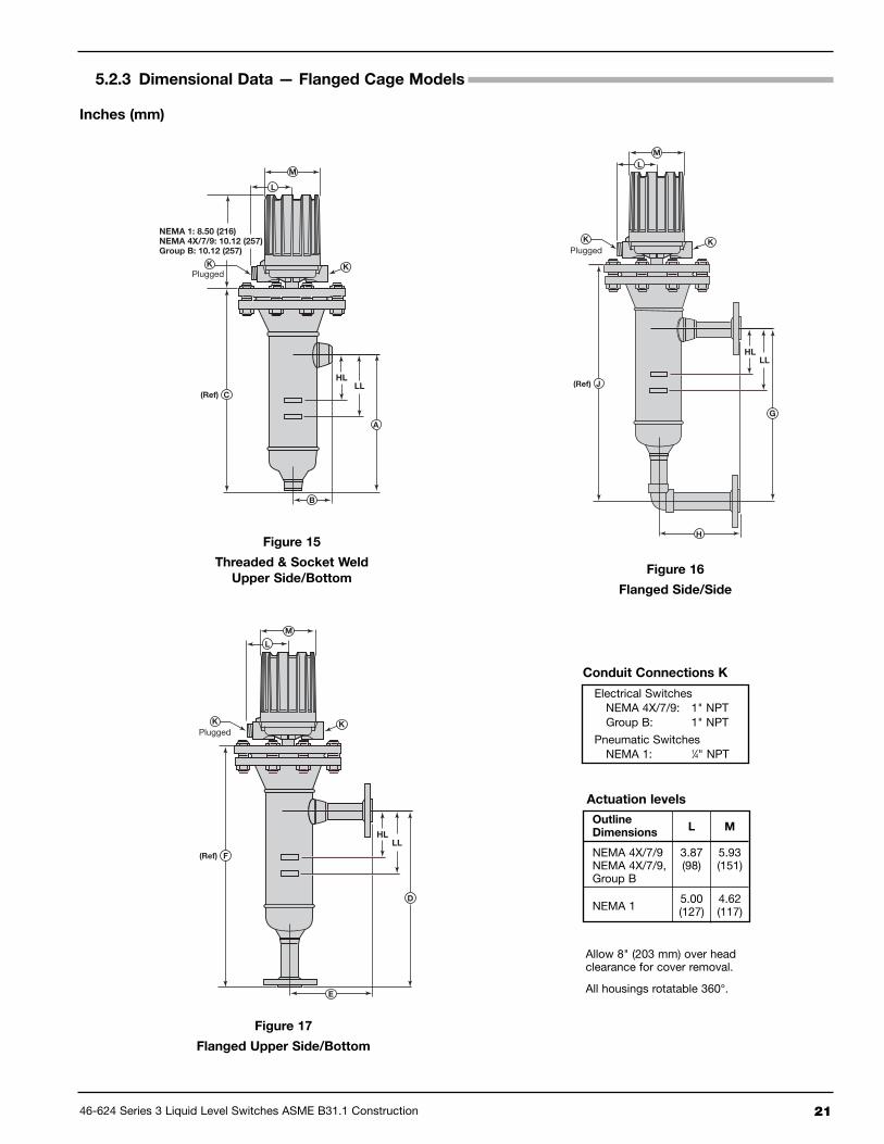
5.2.3 Dimensional Data — Flanged Cage Models
Figure 15
Threaded & Socket Weld
Upper Side/Bottom
L
HLLL
C
A
B
NEMA 1: 8.50 (216)NEMA 4X/7/9: 10.12 (257)Group B: 10.12 (257)
M
(Ref)
KPlugged
K
L
K
HLLL
J
G
M
(Ref)
PluggedK
H
HLLL
D
E
F
M
(Ref)
KPlugged
K
L
Figure 17
Flanged Upper Side/Bottom
Figure 16
Flanged Side/Side
Conduit Connections K
Actuation levels
Allow 8" (203 mm) over headclearance for cover removal.
All housings rotatable 360°.
Electrical SwitchesNEMA 4X/7/9: 1" NPTGroup B: 1" NPT
Pneumatic SwitchesNEMA 1: 1⁄4" NPT
Outline Dimensions
L M
NEMA 4X/7/9 3.87 5.93NEMA 4X/7/9, (98) (151)Group B
NEMA 15.00 4.62(127) (117)
Inches (mm)

22 46-624 Series 3 Liquid Level Switches ASME B31.1 Construction
5.2.4 Dimensional Specifications – Flanged Cage Models
5.2.4.1 150# & 300# ANSI Pressure Ratings
Inches (mm)
CHAMBERS WITH 1-INCH CONNECTIONS
ModelCode
Fig.Size
(Lbs.)
1" NPT Threaded& Socket Weld
1" FlangedUpper Side/Bottom
1" FlangedSide/Side
A B CD
EF g
HJ
Std. 14" Std. 14" Std. 14" Std. 14"
B3F150 9.12
(232)3.63(92)
16.64(423)
12.06(306)
14.00(356)
6.13(156)
19.58(497)
21.51(546)
12.71(323)
14.00(356)
6.13(156)
20.23(514)
21.51(546)
300 9.12(232)
3.63(92)
17.32(440)
12.06(306)
14.00(356)
6.13(156)
20.26(515)
22.19(564)
12.71(323)
14.00(356)
6.13(156)
20.91(531)
22.19(564)
G3F150 10.12
(257)4.69(119)
18.30(465)
13.06(332)
14.00(356)
7.19(183)
21.25(540)
22.19(564)
13.71(348)
14.00(356)
7.19(183)
21.89(556)
22.19(564)
300 10.12(257)
4.69(119)
19.12(486)
13.06(332)
14.00(356)
7.19(183)
22.06(560)
23.00(584)
13.71(348)
14.00(356)
7.19(183)
22.71(577)
23.00(584)
CHAMBERS WITH 11⁄2-INCH CONNECTIONS
ModelCode
Fig.Size
(Lbs.)
11⁄2" NPT Threaded& Socket Weld
11⁄2" FlangedUpper Side/Bottom
11⁄2" FlangedSide/Side
A B CD
EF g
HJ
Std. 14" Std. 14" Std. 14" Std. 14"
B3F150 9.12
(232)3.69(94)
16.64(423)
13.06(332)
14.00(356)
7.13(181)
20.58(523)
21.51(546)
13.71(348)
14.00(356)
7.13(181)
21.23(539)
21.51(546)
300 9.12(232)
3.69(94)
17.32(440)
13.06(332)
14.00(356)
7.13(181)
21.26(540)
22.19(564)
13.71(348)
14.00(356)
7.13(181)
21.91(556)
22.19(564)
G3F150 10.12
(257)4.75(121)
18.30(465)
14.06(357)
14.00(356)
8.19(208)
22.25(565)
22.19(564)
14.71(374)
14.00(356)
8.19(208)
22.89(581)
22.19(564)
300 10.12(257)
4.75(121)
19.12(486)
14.06(357)
14.00(356)
8.19(208)
23.06(586)
23.00(584)
14.71(374)
14.00(356)
8.19(208)
23.71(602)
23.00(584)
CHAMBERS WITH 2-INCH CONNECTIONS
ModelCode
Fig.Size
(Lbs.)
2" NPT Threaded& Socket Weld
2" FlangedUpper Side/Bottom
2" FlangedSide/Side
A B CD
EF g
HJ
Std. 14" Std. 14" Std. 14" Std. 14"
B3F150 9.12
(232)3.81(97)
16.64(423)
13.06(332)
14.00(356)
7.13(181)
20.58(523)
21.51(546)
13.71(348)
14.00(356)
7.13(181)
21.23(539)
21.51(546)
300 9.12(232)
3.81(97)
17.32(440)
13.06(332)
14.00(356)
7.13(181)
21.26(540)
22.19(564)
13.71(348)
14.00(356)
7.13(181)
21.91(556)
22.19(564)
G3F150 10.12
(257)4.88(124)
18.30(465)
14.06(357)
14.00(356)
8.19(208)
22.25(565)
22.19(564)
14.71(374)
14.00(356)
8.19(208)
22.89(581)
22.19(564)
300 10.12(257)
4.88(124)
19.12(486)
14.06(357)
14.00(356)
8.19(208)
23.06(586)
23.00(584)
14.71(374)
14.00(356)
8.19(208)
23.71(602)
23.00(584)
46-624 Series 3 Liquid Level Switches ASME B31.1 Construction 23
46-624 Series 3 Liquid Level Switches ASME B31.1 Construction 24
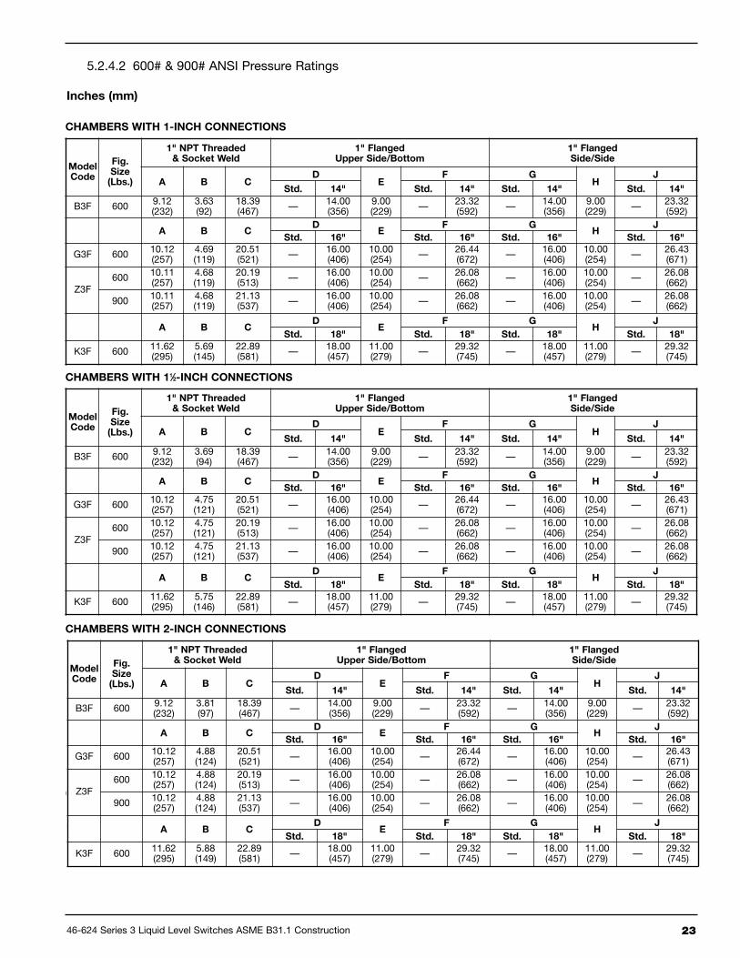
➀ G3F with 600# flanges available in 16" centerlines only.
CHAMBERS WITH 1-INCH CONNECTIONS
ModelCode
Fig.Size
(Lbs.)
1" NPT Threaded& Socket Weld
1" FlangedUpper Side/Bottom
1" FlangedSide/Side
A B CD
EF g
HJ
Std. 14" Std. 14" Std. 14" Std. 14"
B3F 600 9.12(232)
3.63(92)
18.39(467) — 14.00
(356)9.00(229) — 23.32
(592) — 14.00(356)
9.00(229) — 23.32
(592)
A B CD
EF g
HJ
Std. 16" Std. 16" Std. 16" Std. 16"
G3F 600 10.12(257)
4.69(119)
20.51(521) — 16.00
(406)10.00(254) — 26.44
(672) — 16.00(406)
10.00(254) — 26.43
(671)
Z3F600 10.11
(257)4.68(119)
20.19(513) — 16.00
(406)10.00(254) — 26.08
(662) — 16.00(406)
10.00(254) — 26.08
(662)
900 10.11(257)
4.68(119)
21.13(537) — 16.00
(406)10.00(254) — 26.08
(662) — 16.00(406)
10.00(254) — 26.08
(662)
A B CD
EF g
HJ
Std. 18" Std. 18" Std. 18" Std. 18"
K3F 600 11.62(295)
5.69(145)
22.89(581) — 18.00
(457)11.00(279) — 29.32
(745) — 18.00(457)
11.00(279) — 29.32
(745)
CHAMBERS WITH 11⁄2-INCH CONNECTIONS
ModelCode
Fig.Size
(Lbs.)
1" NPT Threaded& Socket Weld
1" FlangedUpper Side/Bottom
1" FlangedSide/Side
A B CD
EF g
HJ
Std. 14" Std. 14" Std. 14" Std. 14"
B3F 600 9.12(232)
3.69(94)
18.39(467) — 14.00
(356)9.00(229) — 23.32
(592) — 14.00(356)
9.00(229) — 23.32
(592)
A B CD
EF g
HJ
Std. 16" Std. 16" Std. 16" Std. 16"
G3F 600 10.12(257)
4.75(121)
20.51(521) — 16.00
(406)10.00(254) — 26.44
(672) — 16.00(406)
10.00(254) — 26.43
(671)
Z3F600 10.12
(257)4.75(121)
20.19(513) — 16.00
(406)10.00(254) — 26.08
(662) — 16.00(406)
10.00(254) — 26.08
(662)
900 10.12(257)
4.75(121)
21.13(537) — 16.00
(406)10.00(254) — 26.08
(662) — 16.00(406)
10.00(254) — 26.08
(662)
A B CD
EF g
HJ
Std. 18" Std. 18" Std. 18" Std. 18"
K3F 600 11.62(295)
5.75(146)
22.89(581) — 18.00
(457)11.00(279) — 29.32
(745) — 18.00(457)
11.00(279) — 29.32
(745)
CHAMBERS WITH 2-INCH CONNECTIONS
ModelCode
Fig.Size
(Lbs.)
1" NPT Threaded& Socket Weld
1" FlangedUpper Side/Bottom
1" FlangedSide/Side
A B CD
EF g
HJ
Std. 14" Std. 14" Std. 14" Std. 14"
B3F 600 9.12(232)
3.81(97)
18.39(467) — 14.00
(356)9.00(229) — 23.32
(592) — 14.00(356)
9.00(229) — 23.32
(592)
A B CD
EF g
HJ
Std. 16" Std. 16" Std. 16" Std. 16"
G3F 600 10.12(257)
4.88(124)
20.51(521) — 16.00
(406)10.00(254) — 26.44
(672) — 16.00(406)
10.00(254) — 26.43
(671)
Z3F600 10.12
(257)4.88(124)
20.19(513) — 16.00
(406)10.00(254) — 26.08
(662) — 16.00(406)
10.00(254) — 26.08
(662)
900 10.12(257)
4.88(124)
21.13(537) — 16.00
(406)10.00(254) — 26.08
(662) — 16.00(406)
10.00(254) — 26.08
(662)
A B CD
EF g
HJ
Std. 18" Std. 18" Std. 18" Std. 18"
K3F 600 11.62(295)
5.88(149)
22.89(581) — 18.00
(457)11.00(279) — 29.32
(745) — 18.00(457)
11.00(279) — 29.32
(745)
5.2.4.2 600# & 900# ANSI Pressure Ratings
Inches (mm)
24 46-624 Series 3 Liquid Level Switches ASME B31.1 Construction
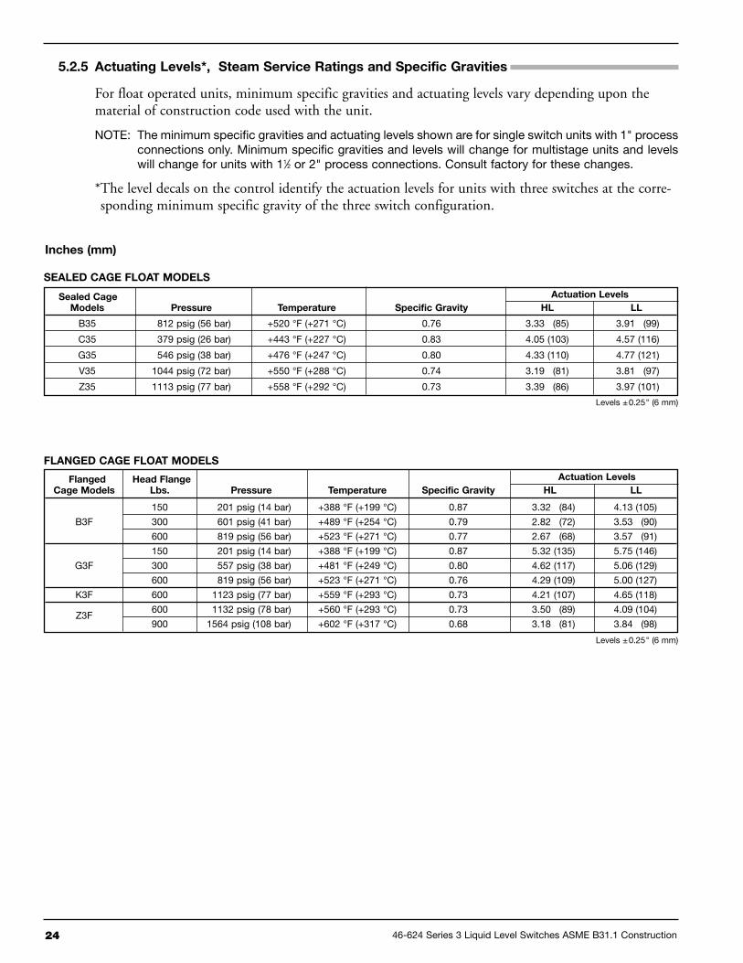
SEALED CAgE FLOAT MODELS
Sealed Cage Actuation Levels
Models Pressure Temperature Specific gravity HL LL
B35 812 psig (56 bar) +520 °F (+271 °C) 0.76 3.33 (85) 3.91 (99)
C35 379 psig (26 bar) +443 °F (+227 °C) 0.83 4.05 (103) 4.57 (116)
G35 546 psig (38 bar) +476 °F (+247 °C) 0.80 4.33 (110) 4.77 (121)
V35 1044 psig (72 bar) +550 °F (+288 °C) 0.74 3.19 (81) 3.81 (97)
Z35 1113 psig (77 bar) +558 °F (+292 °C) 0.73 3.39 (86) 3.97 (101)
Flanged Head Flange Actuation Levels
Cage Models Lbs. Pressure Temperature Specific gravity HL LL
150 201 psig (14 bar) +388 °F (+199 °C) 0.87 3.32 (84) 4.13 (105)
B3F 300 601 psig (41 bar) +489 °F (+254 °C) 0.79 2.82 (72) 3.53 (90)
600 819 psig (56 bar) +523 °F (+271 °C) 0.77 2.67 (68) 3.57 (91)
150 201 psig (14 bar) +388 °F (+199 °C) 0.87 5.32 (135) 5.75 (146)
G3F 300 557 psig (38 bar) +481 °F (+249 °C) 0.80 4.62 (117) 5.06 (129)
600 819 psig (56 bar) +523 °F (+271 °C) 0.76 4.29 (109) 5.00 (127)
K3F 600 1123 psig (77 bar) +559 °F (+293 °C) 0.73 4.21 (107) 4.65 (118)
Z3F600 1132 psig (78 bar) +560 °F (+293 °C) 0.73 3.50 (89) 4.09 (104)
900 1564 psig (108 bar) +602 °F (+317 °C) 0.68 3.18 (81) 3.84 (98)
5.2.5 Actuating Levels*, Steam Service Ratings and Specific gravities
For float operated units, minimum specific gravities and actuating levels vary depending upon thematerial of construction code used with the unit.
NOTE: The minimum specific gravities and actuating levels shown are for single switch units with 1" processconnections only. Minimum specific gravities and levels will change for multistage units and levelswill change for units with 11⁄2 or 2" process connections. Consult factory for these changes.
*The level decals on the control identify the actuation levels for units with three switches at the corre-sponding minimum specific gravity of the three switch configuration.
Inches (mm)
FLANgED CAgE FLOAT MODELS
Levels ±0.25" (6 mm)
Levels ±0.25" (6 mm)
46-624 Series 3 Liquid Level Switches ASME B31.1 Construction 25
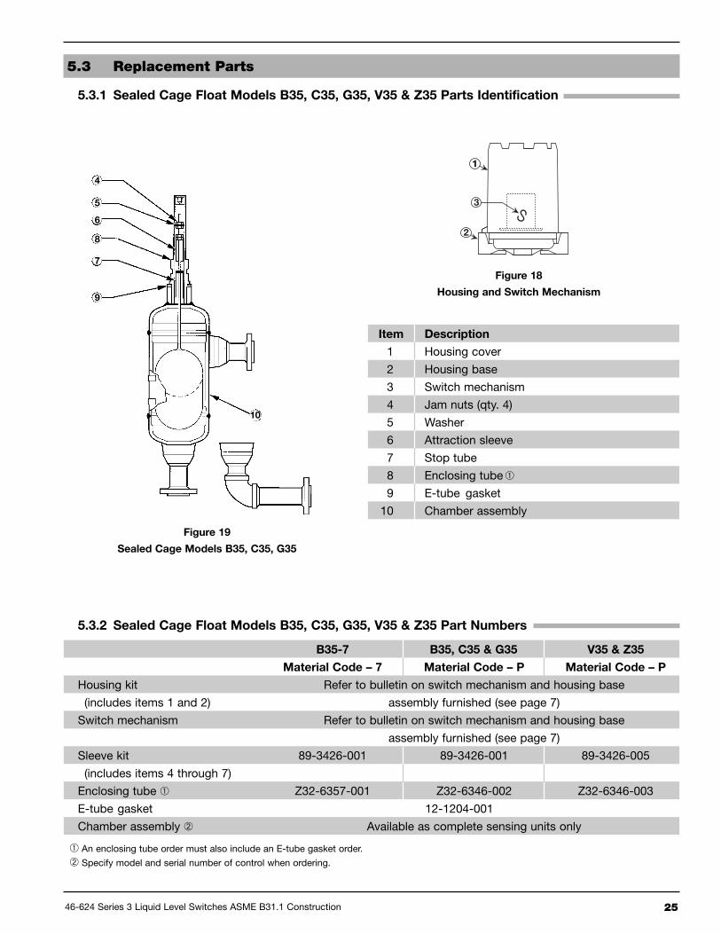
5.3 Replacement Parts
5.3.1 Sealed Cage Float Models B35, C35, g35, v35 & Z35 Parts Identification
Item Description
1 Housing cover
2 Housing base
3 Switch mechanism
4 Jam nuts (qty. 4)
5 Washer
6 Attraction sleeve
7 Stop tube
8 Enclosing tube➀
9 E-tube gasket
10 Chamber assembly
Figure 19
Sealed Cage Models B35, C35, g35
4
5
6
8
7
9
10
➀ An enclosing tube order must also include an E-tube gasket order.
➁ Specify model and serial number of control when ordering.
Figure 18
Housing and Switch Mechanism
11
2
3
5.3.2 Sealed Cage Float Models B35, C35, g35, v35 & Z35 Part Numbers
B35-7 B35, C35 & g35 v35 & Z35
Material Code – 7 Material Code – P Material Code – P
Housing kit Refer to bulletin on switch mechanism and housing base
(includes items 1 and 2) assembly furnished (see page 7)
Switch mechanism Refer to bulletin on switch mechanism and housing base
assembly furnished (see page 7)
Sleeve kit 89-3426-001 89-3426-001 89-3426-005
(includes items 4 through 7)
Enclosing tube ➀ Z32-6357-001 Z32-6346-002 Z32-6346-003
E-tube gasket 12-1204-001
Chamber assembly ➁ Available as complete sensing units only

26 46-624 Series 3 Liquid Level Switches ASME B31.1 Construction
5.3.3 Flanged Cage Float Models B3F, g3F, K3F and Z3F Parts Identification
Item Description
1 Housing cover
2 Housing base
3 Switch mechanism
4 Enclosing tube ➀
5 E-tube gasket
6 Jam nuts (qty. 4)
7 Washer (qty. 2)
8 Attraction sleeve
9 Stop tube
10 Stop strap
11 Screws (qty. 2)
12 Float & stem assembly
13 Head flange gasket
14 Head flange ➁
15 Chamber assembly
Figure 20
Flanged Cage Models B3F, g3F, K3F
6
7
8
4
5
9
10
13
14
11
1215
➀ An enclosing tube order must also include an E-tube gasket order.➁ A head flange order must also include a head flange gasket order.

46-624 Series 3 Liquid Level Switches ASME B31.1 Construction 27
¿ An enclosing tube order must also include an E-tube gasket order.¡ A head flange order must also include a head flange gasket order.¬ Specify model and serial number of control when ordering.
5.3.4 Flanged Cage Float Models B3F, G3F, K3F and Z3F Part Numbers
150# Head Flange 300# Head Flange 600# Head Flange 900# Head Flange
Material Code – P Material Code – P Material Code – P Material Code – P
Housing kit Refer to bulletin on switch mechanism and housing base
(includes items 1 and 2) assembly furnished (see page 7)
Switch mechanism Refer to bulletin on switch mechanism and housing base
assembly furnished (see page 7)
Enclosing tube ¿ Z32-6346-002 Z32-6346-002 Z32-6346-003 Z32-6346-003
E-tube gasket 12-1204-001
Head flange gasket B3F 12-1204-024 12-1204-012 12-1204-002 n/a
G3F 12-1204-025 12-1204-013 12-1204-028 n/a
K3F 12-1204-026 12-1204-027 12-1204-029 n/a
Z3F n/a n/a 12-1204-028 12-1204-047
Float and stem kits B3F 89-3258-005 89-3258-008 89-3258-011 n/a
(includes items G3F 89-3258-006 89-3258-009 89-3258-012 n/a
6 through 13) K3F 89-3258-007 89-3258-010 89-3258-013 n/a
Z3F n/a n/a 89-3258-023 89-3258-024
Head flange ¡ B3F Z04-8637-001 Z04-8637-002 Z04-8637-003 n/a
G3F Z04-8637-004 Z04-8637-005 Z04-8637-006 n/a
K3F Z04-8637-007 Z04-8637-008 Z04-8637-009 n/a
Z3F n/a n/a Z04-8637-006 Z04-8637-013
Chamber assembly ¬ Available as complete sensing units only

28 46-624 Series 3 Liquid Level Switches ASME B31.1 Construction
5.4 Model Numbers
5.4.1 Sealed Cage Models
MODEL NUMBER CODE
SEALED CAGE SIZE AND TANK CONNECTION TYPE
MATERIALS OF CONSTRUCTION
PNEUMATIC SWITCH MECHANISM AND ENCLOSURE
Model
Code
Minimum
Specific
Gravity ➁
Pressure Rating ➀
psig @ °F bar @ °C
100 550 750 800 ➅ 38 288 399 427 ➅
B35 0.69 1000 875 805 783 68.9 60.3 55.5 54.0
C35 0.57 500 438 403 398 34.5 30.2 27.8 27.4
G35 0.54 750 656 604 596 51.7 45.2 41.6 41.1
V35 0.71 2116 1913 1609 1337 145.9 131.9 110.9 92.2
Z35 0.66 2044 1913 1554 1291 140.9 131.9 107.1 89.0
Type
Connection Size
C/C 1" 11⁄2" 2"
Threaded Std. B20 C20 D20
Socket Weld Std. B30 C30 D30
Cage Mounting ANSI Flange Rating (lbs.)
150 300 600 900 150 300 600 900 150 300 600 900
FlangedUpper Side/Bottom
Std. N30 N40 — — P30 P40 — — Q30 Q40 — —
14" N34 N44 N54 N64 P34 P44 P54 P64 Q34 Q44 Q54 Q64
16" — — N56 N66 — — P56 P66 — — Q56 Q66
FlangedSide/Side
Std. S30 S40 — — T30 T40 — — V30 V40 — —
14" S34 S44 S54 S64 T34 T44 T54 T64 V34 V44 V54 V64
16" — — S56 S66 — — T56 T66 — — V56 V66
➃
➃
➂
➂
SwitchDescription
MaximumSupply
Pressure
MaximumProcess
Temperature
BleedOrifice
Diameter
Models B35,C35, & G35
Models V35& Z35
psig bar °F °C inches mm NEMA 1 NEMA 1
Series JBleed Type
100 7 400 204 .063 1.6 JGH JGF
60 4 400 204 .094 2.3 JHH JHF
60 4 700 371 .055 1.3 JJH JJF
Series KNon-Bleed
100 7 400 204 — — — KOF
40 3 400 204 — — KOH —
➀Models are limited to maximum temperature rating ofselected switch mechanism.
➁Minimum specific gravity ratings apply to single stageunits only. Consult factory for two or three stage units.
➂Models V35 and Z35 contain 17–7 ph stainless steelfloats.
➃ Codes for a 16-inch center to center dimension areapplicable to Models G35 with 600# flanges and Z35with 600 & 900# flanges only.
➄ Process temperature based on +100 °F (+38 °C) ambi-ent.
➅ For models built to ASME B31.1 in applications over+750 °F (+399 °C), 100% radiographic examination isrequired. Consult factory for pricing.
∆ HS switches can be used with only materials of con-struction code 1 on models V35 & Z35
P Carbon steel chamber, 316L stainless steel float, 400 series stainless steel sleeve, ASME B31.1 Construction
7 P22/F22 Chrome-Moly chamber, 347 ss float, 400 series ss sleeve, ASME B31.1 Construction, model B35 only

46-624 Series 3 Liquid Level Switches ASME B31.1 Construction 29
ELECTRIC SWITCH MECHANISM AND ENCLOSURE
SwitchDescription
Process ➄Temperature
Range
°F (°C)
ContactsSet
Points
Models B35, C35 & g35 Models v35 & Z35
TyPE 4X/7/9 Aluminum Enclosure
Class I, Div 1Groups C&D
Class I, Div 1Group B
ATEXEx II 2 G EEx
d IIC T6
Class I, Div 1Groups C&D
Class I, Div 1Group B
ATEXEx II 2 G EEx
d IIC T6
Series BSnap Switch
-40 to +250(-40 to +121)
SPDT1 BKA BKJ BCC BKB BKK BC92 BLA BLJ BDC BLB BLK BD93 BMA BMJ BEC BMB BMK BE9
DPDT1 BNA BNJ BFC BNB BNK BF92 BOA BOJ BGC BOB BOK BG9
Series CSnap Switch
-40 to +450(-40 to +232)
SPDT1 CKA CKJ CCC CKB CKK CC92 CLA CLJ CDC CLB CLK CD93 CMA CMJ CEC CMB CMK CE9
DPDT1 CNA CNJ CFC CNB CNK CF92 COA COJ CGC COB COK CG9
Series D DC CurrentSnap Switch
-40 to +250(-40 to +121)
SPDT1 DKB DKK DC9 DKB DKK DC92 DLB DLK DD9 DLB DLK DD93 DMB DMK DE9 DMB DMK DE9
DPDT1 DNB DNK DF9 DNB DNK DF92 DOB DOK DG9 DOB DOK DG9
Series FHermetically Sealed
Snap Switch
-50 to +750(-46 to +399)
SPDT1 FKA FKJ FCC FKB FKK FC92 FLA FLJ FDC FLB FLK FD9
DPDT1 FNA FNJ FFC FNB FNK FF92 FOA FOJ FGC FOB FOK FG9
Series HS ∆Hermetically Sealed5-amp Snap Switchwith Wiring Leads
-50 to +400(-46 to +204)
SPDT1 HMJ HMK
N/A
HMJ HMK
N/A2 HMN HMP HMN HMP
DPDT1 HMS HMT HMS HMT2 HMY HMZ HMY HMZ
Series HS ∆Hermetically Sealed5-amp Snap Switchwith Terminal Block
-50 to +400(-46 to +204)
SPDT 1 HM3 HM4 HA9 HM3 HM4 HA9
DPDT 1 HM7 HM8 HB9 HM7 HM8 HB9
Series RHigh TemperatureSnap Switch
-40 to +750(-40 to +399)
SPDT1 RKB RKK RC9 RKB RKK RC92 RLB RLK RD9 RLB RLK RD9
DPDT1 RNB RNK RF9 RNB RNK RF92 ROB ROK RG9 ROB ROK RG9
Series 8Hermetically Sealed
Snap Switch
-50 to +750(-46 to +399)
SPDT1 8KA 8KJ 8CC 8KB 8KK 8C92 8LA 8LJ 8DC 8LB 8LK 8D93 8MA 8MJ 8EC 8MB 8MK 8E9
DPDT1 8NA 8NJ 8FC 8NB 8NK 8F92 8OA 8OJ 8GC 8OB 8OK 8G9
Series 9High TemperatureHermetically Sealed
Snap Switch
-50 to +750(-46 to +399)
SPDT1 9KA 9KJ 9CC 9KB 9KK 9C92 9LA 9LJ 9DC 9LB 9LK 9D93 9MA 9MJ 9EC 9MB 9MK 9E9
DPDT1 9NA 9NJ 9FC 9NB 9NK 9F92 9OA 9OJ 9GC 9OB 9OK 9G9
SwitchDescription
Process ➄Temp. Range
°F (°C)
ContactsSet
Points
CS/Aluminum Cast Iron CS/Aluminum Cast Iron
NEMA 4XClass I, Div 1Groups C&D
Class I, Div 1Group B
NEMA 4XClass I, Div 1Groups C&D
Class I, Div 1Group B
Series RHigh TemperatureSnap Switch
-40 to +1000(-40 to +538)
SPDT1 R1M RKM RKW R1M RKM RKW2 R3M RLM RLW R3M RLM RLW
DPDT1 RDM RNM RNW RDM RNM RNW2 REM ROM ROW REM ROM ROW
Series 9High TemperatureHermetically Sealed
Snap Switch
-50 to +1000(-46 to +538)
SPDT1 9AD 9KD 9KV 9AM 9KM 9KW2 9BD 9LD 9LV 9BM 9LM 9LW3 9CD 9MD 9MV 9CM 9MM 9MW
DPDT1 9DD 9ND 9NV 9DM 9NM 9NW2 9ED 9OD 9OV 9EM 9OM 9OW

30 46-624 Series 3 Liquid Level Switches ASME B31.1 Construction
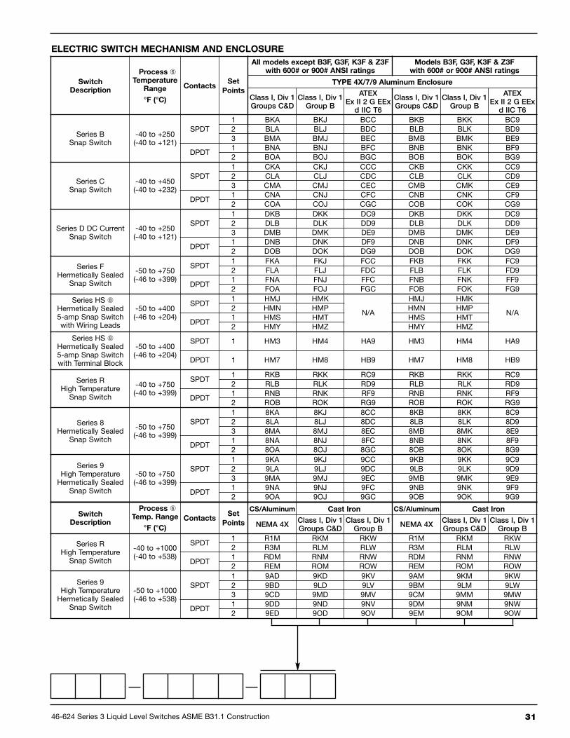
5.4.2 Flanged Cage Models
SwitchDescription
MaximumSupply
Pressure
MaximumProcess
Temperature
BleedOrifice
Diameter
All Modelsexcept: B3F, G3F,
K3F & Z3Fwith 600 lb.
Head Flanges
ModelsB3F, G3F,
K3F & Z3Fwith 600 & 900 lb.
Head Flanges
psig bar °F °C inches mm NEMA 1 NEMA 1
Series JBleed Type
100 7 400 204 .063 1.6 JGH JGF
50 4 400 204 .094 2.3 JHH JHF
60 4 700 371 .055 1.3 JJH JJF
Series KNon-Bleed
100 7 400 204 — — — KOF
40 3 400 204 — — KOH —
MODEL NUMBER CODE
CAGE SIZE AND TANK CONNECTION TYPE
P Carbon steel chamber, 316L stainless steel float, 400 stainless steel sleeve, ASME B31.1 Construction
MATERIALS OF CONSTRUCTION
PNEUMATIC SWITCH MECHANISM AND ENCLOSURE
Model
Code
HeadFlange
ANSI Class
MinimumS.G.➀
Gravity➀
Pressure Rating ➁
psig @ °F bar @ °C
1 100 550 750 800 ∆ 38 288 399 427 ∆
B3F
150# 0.78 285 155 95 80 19.6 10.7 6.5 5.5
300# 0.66 740 588 505 410 51.0 39.6 34.8 28.3
600# 0.66 1000 875 805 795 68.9 60.3 55.5 54.8
G3F
150# 0.41 285 155 95 80 19.6 10.7 6.5 5.5
300# 0.55 740 588 505 410 51.0 45.0 41.4 28.3
600# 0.70 1000 875 805 795 68.9 60.3 55.5 54.8
K3F 600# 0.60 1480 1170 1015 825 102.0 80.7 70.0 56.9
Z3F600#
0.671480 1170 1015 825 102.0 80.7 70.0 56.9
900# 2044 1913 1554 1291 140.9 131.9 107.1 89.0
ConnectionType
Connection Size
C/C 1" 11⁄2" 2"
ANSI Head Flange Rating (lbs.)
150 300 600 900 150 300 600 900 150 300 600 900
Threaded Std. B20 B60 B80 B40 C20 C60 C80 C40 D20 D60 D80 D40
Socket Weld Std. B30 B70 B90 B50 C30 C70 C90 C50 D30 D70 D90 D50
FlangedUpper Side/Bottom
Std. N30 N40 — — P30 P40 — — Q30 Q40 — —
14" N34 N44 N54 N64 P34 P44 P54 P64 Q34 Q44 Q54 Q64
16" — — N56 N66 — — P56 P66 — — Q56 Q66
18" — — N58 — — — P58 — — — Q58 —
FlangedSide/Side
Std. S30 S40 — — T30 T40 — — V30 V40 — —14" S34 S44 S54 S64 T34 T44 T54 T64 V34 V44 V54 V64
16" — — S56 S66 — — T56 T66 — — V56 V66
18" — — S58 — — — T58 — — — Q58 —
➃
➄
➃
➄
➂
➂
➀ Minimum specific gravity ratings apply to single stage units only. Consultfactory for two or three stage units.
➁ Models are limited to maximum temperature rating of selected switchmechanism.
➂ Models Z3F & K3F contain 7–17 ph stainless steel floats.
➃ Codes for a 16 inch center to center dimension are applicable to modelsG3F and Z3F with 600# flanges only.
➄ Codes for an 18-inch center to center dimension are applicable to K3Fmodel only.
➅ Process temperature based on +100 °F (+38 °C) ambient.
∆ For models built to ASME B31.1 in applications over +750 °F (+399 °C),100% radiographic examination is required. Consult factory for pricing.
➇ HS switches can be used with only materials of construction code 1 on allmodels with 600# or 900# ANSI rating.
46-624 Series 3 Liquid Level Switches ASME B31.1 Construction 31
ELECTRIC SWITCH MECHANISM AND ENCLOSURE
SwitchDescription
Process ➅Temperature
Range
°F (°C)
ContactsSet
Points
All models except B3F, g3F, K3F & Z3Fwith 600# or 900# ANSI ratings
Models B3F, g3F, K3F & Z3Fwith 600# or 900# ANSI ratings
TyPE 4X/7/9 Aluminum Enclosure
Class I, Div 1Groups C&D
Class I, Div 1Group B
ATEXEx II 2 G EEx
d IIC T6
Class I, Div 1Groups C&D
Class I, Div 1Group B
ATEXEx II 2 G EEx
d IIC T6
Series BSnap Switch
-40 to +250(-40 to +121)
SPDT1 BKA BKJ BCC BKB BKK BC92 BLA BLJ BDC BLB BLK BD93 BMA BMJ BEC BMB BMK BE9
DPDT1 BNA BNJ BFC BNB BNK BF92 BOA BOJ BGC BOB BOK BG9
Series CSnap Switch
-40 to +450(-40 to +232)
SPDT1 CKA CKJ CCC CKB CKK CC92 CLA CLJ CDC CLB CLK CD93 CMA CMJ CEC CMB CMK CE9
DPDT1 CNA CNJ CFC CNB CNK CF92 COA COJ CGC COB COK CG9
Series D DC CurrentSnap Switch
-40 to +250(-40 to +121)
SPDT1 DKB DKK DC9 DKB DKK DC92 DLB DLK DD9 DLB DLK DD93 DMB DMK DE9 DMB DMK DE9
DPDT1 DNB DNK DF9 DNB DNK DF92 DOB DOK DG9 DOB DOK DG9
Series FHermetically Sealed
Snap Switch
-50 to +750(-46 to +399)
SPDT1 FKA FKJ FCC FKB FKK FC92 FLA FLJ FDC FLB FLK FD9
DPDT1 FNA FNJ FFC FNB FNK FF92 FOA FOJ FGC FOB FOK FG9
Series HS ➇Hermetically Sealed5-amp Snap Switchwith Wiring Leads
-50 to +400(-46 to +204)
SPDT1 HMJ HMK
N/A
HMJ HMK
N/A2 HMN HMP HMN HMP
DPDT1 HMS HMT HMS HMT2 HMY HMZ HMY HMZ
Series HS ➇Hermetically Sealed5-amp Snap Switchwith Terminal Block
-50 to +400(-46 to +204)
SPDT 1 HM3 HM4 HA9 HM3 HM4 HA9
DPDT 1 HM7 HM8 HB9 HM7 HM8 HB9
Series RHigh TemperatureSnap Switch
-40 to +750(-40 to +399)
SPDT1 RKB RKK RC9 RKB RKK RC92 RLB RLK RD9 RLB RLK RD9
DPDT1 RNB RNK RF9 RNB RNK RF92 ROB ROK RG9 ROB ROK RG9
Series 8Hermetically Sealed
Snap Switch
-50 to +750(-46 to +399)
SPDT1 8KA 8KJ 8CC 8KB 8KK 8C92 8LA 8LJ 8DC 8LB 8LK 8D93 8MA 8MJ 8EC 8MB 8MK 8E9
DPDT1 8NA 8NJ 8FC 8NB 8NK 8F92 8OA 8OJ 8GC 8OB 8OK 8G9
Series 9High TemperatureHermetically Sealed
Snap Switch
-50 to +750(-46 to +399)
SPDT1 9KA 9KJ 9CC 9KB 9KK 9C92 9LA 9LJ 9DC 9LB 9LK 9D93 9MA 9MJ 9EC 9MB 9MK 9E9
DPDT1 9NA 9NJ 9FC 9NB 9NK 9F92 9OA 9OJ 9GC 9OB 9OK 9G9
SwitchDescription
Process ➅Temp. Range
°F (°C)
ContactsSet
Points
CS/Aluminum Cast Iron CS/Aluminum Cast Iron
NEMA 4XClass I, Div 1Groups C&D
Class I, Div 1Group B
NEMA 4XClass I, Div 1Groups C&D
Class I, Div 1Group B
Series RHigh TemperatureSnap Switch
-40 to +1000(-40 to +538)
SPDT1 R1M RKM RKW R1M RKM RKW2 R3M RLM RLW R3M RLM RLW
DPDT1 RDM RNM RNW RDM RNM RNW2 REM ROM ROW REM ROM ROW
Series 9High TemperatureHermetically Sealed
Snap Switch
-50 to +1000(-46 to +538)
SPDT1 9AD 9KD 9KV 9AM 9KM 9KW2 9BD 9LD 9LV 9BM 9LM 9LW3 9CD 9MD 9MV 9CM 9MM 9MW
DPDT1 9DD 9ND 9NV 9DM 9NM 9NW2 9ED 9OD 9OV 9EM 9OM 9OW

BulletiN: 46-624.9
eFFective: August 2017
suPersedes: June 2016
705 Enterprise Street • Aurora, Illinois 60504-8149 • [email protected] • www.magnetrol.com
Copyright © 2017 Magnetrol International, Incorporated
Service Policy
Owners of MAGNETROL may request the return of acontrol or any part of a control for complete rebuilding orreplacement. They will be rebuilt or replaced promptly.Controls returned under our service policy must bereturned by Prepaid transportation. MAGNETROL willrepair or replace the control at no cost to the purchaser (orowner) other than transportation if:
1. Returned within the warranty period; and2. The factory inspection finds the cause of the claim
to be covered under the warranty.
If the trouble is the result of conditions beyond our con-trol; or, is NOT covered by the warranty, there will becharges for labor and the parts required to rebuild orreplace the equipment.
In some cases it may be expedient to ship replacementparts; or, in extreme cases a complete new control, toreplace the original equipment before it is returned. If thisis desired, notify the factory of both the model and serialnumbers of the control to be replaced. In such cases, cred-it for the materials returned will be determined on thebasis of the applicability of our warranty.
No claims for misapplication, labor, direct or consequen-tial damage will be allowed.
Return Material Procedure
So that we may efficiently process any materials that arereturned, it is essential that a “Return MaterialAuthorization” (RMA) number be obtained from the factory, prior to the material’s return. This is availablethrough MAGNETROL’s local representative or by contacting the factory. Please supply the followinginformation:
1. Company Name2. Description of Material3. Serial Number4. Reason for Return5. Application
Any unit that was used in a process must be properlycleaned in accordance with OSHA standards, before it isreturned to the factory.
A Material Safety Data Sheet (MSDS) must accompanymaterial that was used in any media.
All shipments returned to the factory must be by prepaidtransportation.
All replacements will be shipped F.O.B. factory.
Assured quAlity & service cost less